

Page 1
INSTALLATION INSTRUCTIONS
Product Revision Form
7160-0377
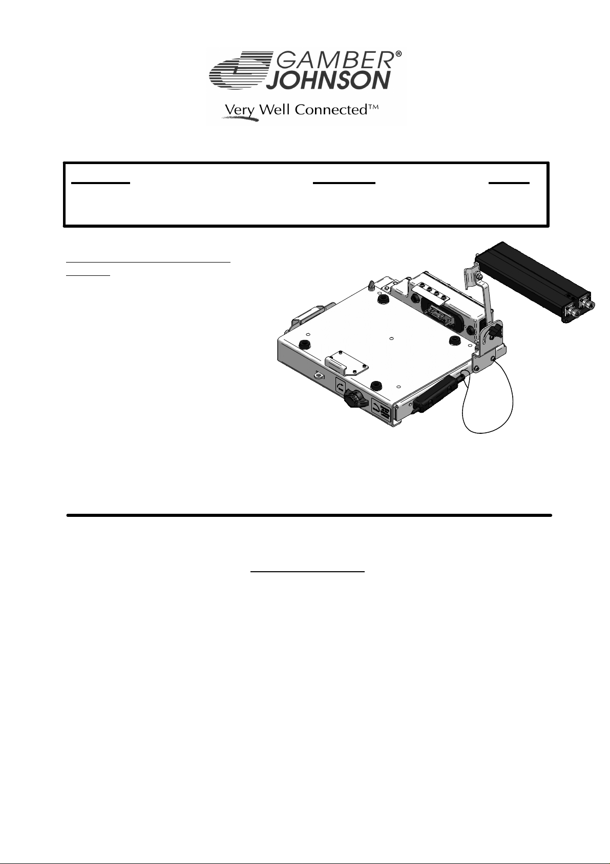
Recon CF31 Military Docking Station
This document is for the following
products:
7160-0377 = Recon CF31 Military
Docking Station.
The dock will hold a Panasonic CF30 or
CF31 computer. A CF29 computer can
be mounted with the addition of a .06"
shim under the front hook.
*This document is for the docking station only. For instructions on features, set-up and operation
of the CF31 computer, please refer to the manuals provided by Panasonic with the computer.
**This docking station is designed to be used with a variety of Gamber-Johnson mounting
systems. Installation instructions for other Gamber-Johnson products are provided with each
individual product.
Rev. A INST-578
Printing Spec: PS-001
IMPORTANT SAFETY INFORMATION for
INSTALLERS
Safety is dependent on the proper installation and servicing of this docking station. It is
important to read and follow all instructions before installing this product.
To properly install a Gamber-Johnson docking station you must have a good understanding
of automotive electrical procedures and systems, along with proficiency in the installation
and service of aftermarket vehicle equipment.
There are no adjustments required at any time of the electrical components within the
docking station.
Product Mounting Disclaimer
Gamber-Johnson is not liable under any theory of contract or tort law for any loss, damage, personal injury, special, incidental or consequential damages for personal injury or other damage
of any nature arising directly or indirectly as a result of the improper installation or use of its products in vehicle or any other application. In order to safely install and use Gamber-Johnson
products full consideration of vehicle occupants, vehicle systems (i.e., the location of fuel lines, brakes lines, electrical, drive train or other systems), air-bags and other safety equipment is
required. Gamber-Johnson specifically disclaims any responsibility for the improper use or installation of its products not consistent with the original vehicle manufactures specifications
and recommendations, Gamber-Johnson product instruction sheets, or workmanship standards as endorsed through the Gamber-Johnson Certified Installer Program.
© copyright 2010 Gamber-Johnson, LLC
Opening the port replication housing will void the product warranty.
If you need assistance or have questions, call Gamber-Johnson at 1-800-456-6868
Page 2

During Installation
DO NOT connect this docking station to the vehicle battery until:
1. ALL other electrical connections are made
2. Mounting of ALL components is complete
3. VERIFICATION that no shorts exist in the entire system
DO NOT install equipment or route wiring or chords in the deployment path of any
air bag.
When drilling into the vehicle, DO make sure that both sides of the surface are
clear of anything that could be damaged.
It is recommended to install a
32V - 10Amp in-line fuse connected as close to the
battery or power source as possible.
CAUTION: If wiring is shorted to the frame, high current conductors can cause
hazardous sparks resulting in electrical fires or flying molten metal.
After Installation
Test the docking station to ensure that it is working properly.
File these instructions in a safe place and refer to them when performing
maintenance or re-installing.
WARNING: Failure to follow all safety precautions and instructions may result
in property damage, serious injury or death.
PRE-INSTALLATION RECOMMENDATIONS
Conduct a "Bench Test"
Gamber-Johnson strongly advises a "bench test" be conducted to verify that all electronic
and software issues are resolved prior to installation:
1. Make sure computer is operational by itself.
2. Insert computer into docking station and verify that the computer is operating in the
dock.
3. Interconnect entire assembly and verify start-up of all components, including other
equipment (printers, modems, scanners, etc.).
*Gamber-Johnson also recommends positioning of all mounts and equipment in the vehicle
prior to the actual install to verify that mounting locations are safe and practical.
Page 3
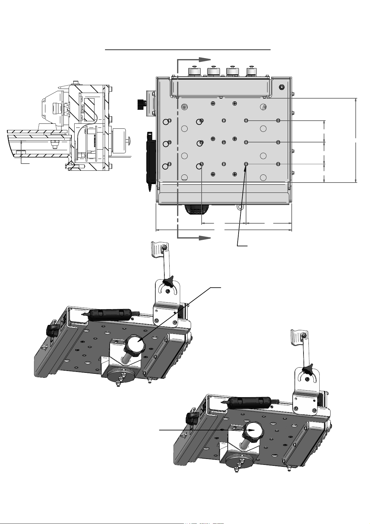
Standard Mounting Hole Locations
A
.750 clear
SECTION A-A
1/4-20unc x .63 stainless
steel mounting bolts and
lock washers supplied in
hardware bag. Torque to
65-85 in/lbs.
A
A
A
A
A
A
4.094 4.20
12.49
2.00
7.72
2.00
1.69
A
1/4-20unc threaded inserts
marked "A" for mounting to
Gamber Johnson standard
mounting equipment
Gamber Johnson DS-Clevis mounted
to the rear set of mount holes
(This is the recommended mounting
location because the center of gravity
is centered over the mount)
Gamber Johnson DS-Clevis mounted
to the front set of mount holes
(Secondary mounting location for use if
vehicle space requires offsetting the dock
over the mount)
Page 4

Isolator Mounting Hole Locations
7160-0439
Wire Rope Isolator Assembly
Weight = 3.15 lbs
B
B
B
2.047
5.00 5.00
B
B
B
B
2.00
B
2.00
B
1.69
1.24
1/4-20unc threaded inserts marked "B"
for mounting to Gamber Johnson
wire rope isolator assembly
Gamber Johnson Wire Rope
Isolator Assembly mounted to the
rear set of isolator mounting holes
(This is the recommended mounting
location because the center of gravity
is centered over the mount)
1/4-20unc threaded inserts for mounting
to Gamber Johnson mounting equipment
Gamber Johnson Wire Rope
Isolator Assemlby mounted to the
front set of isolator mounting holes
(Secondary mounting location for use if
vehicle space requires offsetting the dock
over the mount)
Page 5

Dock and Power Supply Dimensions
1.04
7160-0377
Recon CF31 Military Docking
Stattion Weight = 11 lbs
11.74
5.46
13.66
8.20
3.00
1.25
1.25
12.49
7.18 1.43
10.47
10.00
9.60
.31
.88
4.20
2.33
3.92
2.44
.91
7.86
.62
J6 - Female connector
(Out-put power to dock)
.69
1.25
O
.2006X mounting holes
Note: mounting hardware
supplied by others
1/4-20unc stainless steel ground stud
(torque nut to 65-85 in/lbs)
.21
J5 - Male connector
(In-put power from vehicle)
18-32 Vdc Power Supply
Weight = 1.50 lbs
Page 6

Tethered Connector Cover
(Has option of being relocated to
other side of dock by customer)
Slide Plate
Hasp for padlock with
9/32" dia. shackle
Features
Screen Support
(Shipped unattached - has Option of being
mounted to either side of the dock by customer)
Docking Connector
Power Switch
Note: attach
screen support
and stylus with
hardware found
in hardware bag
7120-0591
Wing Turn Latch
Tethered Stylus
(Shipped unattached - Has option
of being relocated to other side of
dock by customer)
Data Cable Ports
with Lanyard attached Caps
(D38999 Shell Size 13)
Power Cable Port
with Lanyard attached Cap
(D38999 Shell Size 9)
1/4-20unc x .63 Stainless
Steel Ground Stud
(torque nut to 65-85 in/lbs)
Page 7

PWR_OUT
PWR_OUT
PWR_OUT
Connector Data cables are not supplied with the docking station
NOTES:
POWER SUPPLY CONNECTORS
15Vdc OUTPUT POWER TO
DOCK
1. It is recommended to install a
in-line fuse connected as close to the battery
or power source as possible.
2. The estimated power draw on the 28Vdc
vehicle supply is 3 Amps.
3. MIL STD 461F was achieved by using
completely shielded cables. Cables
containing USB signals must not exceed 5
meters in length.
18 - 32Vdc INPUT POWER FROM
VEHICLE
32V - 10Amp
AMPHENOL CONNECTOR
JD38999/20FA35SN
J6 PIN # J6 SIGNAL
1
2 GND
3 GND
4 GND
5
6
J1 = INPUT POWER
AMPHENOL CONNECTOR
#91-569781-35G
J1 PIN # J1 SIGNAL
1 PWR_IN
2 GND
3 GND
4 GND
5 PWR_IN
6 PWR_IN
AMPHENOL CONNECTOR
JD38999/20FA35PN
J5 PIN # J5 SIGNAL
1 PWR_IN
2 GND
3 GND
4 GND
5 PWR_IN
6 PWR_IN
J2 = DATA CABLE
AMPHENOL CONNECTOR
#91-569783-35H
(1)VIDEO, (1)AUDIO,
(1)USB ETHERNET
J2 PIN # J2 SIGNAL
1 VSYNC
2 HSYNC
3 DDC2BD
4 NC
5 SYNC_GND
6 +5V_VIDEO
7 CRTB_GND
8 CRTG_GND
9 CRTR_GND
10 GND
11 NC
12 CRTB
13 CRTG
14 CRTR
15 USB_RXP
16 USB_TXN
17 USB_TXP
18 HP_R
19 HP_L
20 AGND
21 DDC2BC
22 USB_RXN
Page 8

Connector Data cables are not supplied with the docking station
MIL STD 461F was achieved by using completely shielded cables. Cables
containing USB signals must not exceed 5 meters in length.
J3 = DATA CABLE
AMPHENOL CONNECTOR
#91569783-35J
(2) USB, (1) TRUE ETHERNET,
(2) 5 Vdc POWER OUTPOUTS
J3 PIN# J3 SIGNAL
1 PPTMDI22 PPTMDI2+
3 PPTMDI14 PPTMDI1+
5 PPTMDI06 PPTMDI0+
7 USB4_GND
8 USBDP4
9 USBDM4
10 USB4_PWR
11 USB3_GND
12 USBDP3
13 USBDM3
14 USB3_PWR
15 +5V_GND
16 +5VDC
17 +5VDC
18 NC
19 NC
20 PPTMDI321 PPTMDI3+
22 +5V_GND
J4 = DATA CABLE
AMPHENOL CONNECTOR
#91-569783-35S
(2) SERIAL, & (1) USB
J4 PIN # J4 SIGNAL
1 GND
2 DTR2
3 SOUT2
4 SIN2
5 DCD2
6 RI1
7 CTS1
8 R TS1
9 DSR1
10 GND
11 DTR1
12 SOUT1
13 SIN1
14 DCD1
15 USBDP2
16 USBDM2
17 USB2_PWR
18 RI2
19 CTS2
20 RTS2
21 DSR2
22 USB2_GND
Page 9

Pin Acronyms List for 7160-0377
1. J1 pins 1, 5 and 6 = Input Power (+28Vdc)
2. J1 pins 2, 3 and 4 = Input Power Ground
3. J2 pins 1-14 and 21 = Video Output
4. J2 pins 15-17 and 22 = USB/Ethernet Output
a. USB_TXN = Transmit Data Negative Signal
b. USB_TXP = Transmit Data Plus Signal
c. USB_RXN = Receive Data Negative Signal
d. USB_RXP = Receive Data Plus Signal
5. J2 pins 18-20 = Audio Output
a. HP_R = Headphone Right Audio Output
b. HP_L = Headphone Left Audio Output
c. AGND = Audio Ground
6. J3 pins 1-6 and 20-21 = 1GHz Ethernet
a. PPTMDI2- = Bi-Directional pair 2- or C- (J3-1)
b. PPTMDI2+ = Bi-Directional pair 2+ or C+ (J3-2)
c. PPTMDI1- = Bi-Directional pair 1- or B- (J3-3)
d. PPTMDI1+ = Bi-Directional pair 1+ or B+ (J3-4)
e. PPTMDI0- = Bi-Directional pair 0- or A- (J3-5)
f. PPTMDI0+ = Bi-Directional pair 0+ or A+ (J3-6)
g. PPTMDI3- = Bi-Directional pair 3- or D- (J3-20)
h. PPTMDI3+ = Bi-Directional pair 3+ or D+ (J3-21)
7. J3 pins 7-10 = USB Port
a. USB4_PWR = USB #4 Port +5Vdc
b. USBDP4 = USB #4 Port Data +
c. USBDM4 = USB #4 Port Datad. USB4_GND = USB #4 Port Ground
8. J3 pins 11-14 = USB Port
a. USB3_PWR = USB #3 Port +5Vdc
b. USBDP3 = USB #3 Port Data +
c. USBDM3 = USB #3 Port Datad. USB3_GND = USB #3 Port Ground
9. J3 pins 15-17 and 22 = Auxiliary +5Vdc Output max 4 amps
a. +5VDC = +5 Volts Output (J3-16 & 17) (4 Amps max when combined)
b. +5VDC_GND = +5 Volts Output Return (J3-15 & 22)
10. J4 pins 1-5 and 18-21 = Serial Port #2
11. J4 pins 6-14 = Serial Port #1
12. J4 pins 15-17 and 22 = USB Port
a. USB2_PWR = USB #2 Port +5Vdc
b. USBDP2 = USB #2 Port Data +
c. USBDM2 = USB #2 Port Datad. USB2_GND = USB #2 Port Ground
Page 10

Installing the CF31
computer into the dock
Step 1: Make sure the sliding door, located on the back surface
of the computer, has been opened to expose the computers'
docking connector.
Step 2: Make sure the power switch on the dock is in the "OFF"
position. Panasonic does not recomend "Hot-Docking" the
Toughbook computers.
Make sure no loose or foreign objects are on the surface of the
dock, the connector cover is mounted in the storage location on
the side of the dock, and the slide plate is in the forward
location.
Step 3: Place the front edge of the computer into the dock. The
pocket on the front edge of the computer will fit onto the hook on
the front edge of the dock.
Step 4: Lower the back edge of the computer down onto the slide
plate and guide pins.
Step 5: Push the slide plate with computer, back onto the docking
connector.
Step 6: Rotate the wing turn compression latch 180 degrees
clockwise. The alignment marks on the latch will align when the
latch is in the compressed state. A padlock with a 9/32" diameter
shackle can be used to help secure the computer to the docking
station.
Step 7: Turn "ON" the power switch on the dock to connect power
to the unit.
 Loading...