

Page 1
INSTALLATION INSTRUCTIONS
Product
7160-0326, 7160-0327, 7160-0353, 7160-0354, 7160-0347
Description - Charger Console 2011+
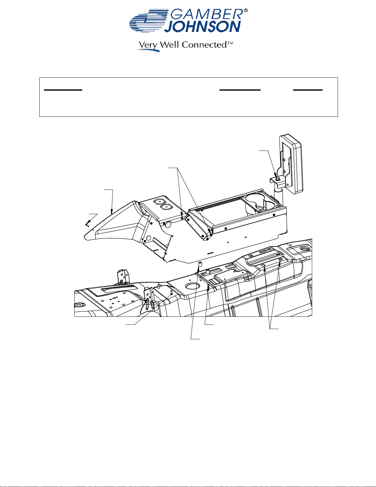
AND ANGLE ADJUSTMENT
#6-32 PAN HEAD SCREWS
REMOVE FOR SERVICE
DASH FILL EXTENSION
#6 SELF DRILLING
SCREW
Revision
Rev.G
ARMREST HEIGHT
Form
INST-516
Printing Spec:
PS-001
REAR STUDSFRONT STUDS
SPACER BUSHING
REAR MOUNTING
POINTS
1. Before installing console into vehicle, unpack and install the Dash Fill Extensions
(one per side) to the console box using the provided #6-32 nylock nuts (3 per side).
2. Remove factory console and/or top plate from vehicle.
3. Disconnect the factory harness and remove the low frequency antenea (LFA) from
the stock plastic center console.
Product Mounting Disclaimer
Product Mounting Disclaimer
Gamber-Johnson is not liable under any theory of contract or tort law for any loss, damage, personal injury, special, incidental or consequential damages for personal injury or other damage
Gamber-Johnson is not liable under any theory of contract or tort law for any loss, damage, personal injury, special, incidental or consequential damages for personal injury or other damage
of any nature arising directly or indirectly as a result of the improper installation or use of its products in vehicle or any other application. In order to safely install and use Gamber-Johnson
of any nature arising directly or indirectly as a result of the improper installation or use of its products in vehicle or any other application. In order to safely install and use Gamber-Johnson
products full consideration of vehicle occupants, vehicle systems (i.e., the location of fuel lines, brakes lines, electrical, drive train or other systems), air-bags and other safety equipment is
products full consideration of vehicle occupants, vehicle systems (i.e., the location of fuel lines, brakes lines, electrical, drive train or other systems), air-bags and other safety equipment is
required. Gamber-Johnson specifically disclaims any responsibility for the improper use or installation of its products not consistent with the original vehicle manufactures specifications
required. Gamber-Johnson specifically disclaims any responsibility for the improper use or installation of its products not consistent with the original vehicle manufactures specifications
and recommendations, Gamber-Johnson product instruction sheets, or workmanship standards as endorsed through the Gamber-Johnson Certified Installer Program.
and recommendations, Gamber-Johnson product instruction sheets, or workmanship standards as endorsed through the Gamber-Johnson Certified Installer Program.
© Copyright 2012 Gamber-Johnson, LLC
If you need assistance or have questions, call Gamber-Johnson at 1-800-456-6868
Page 2
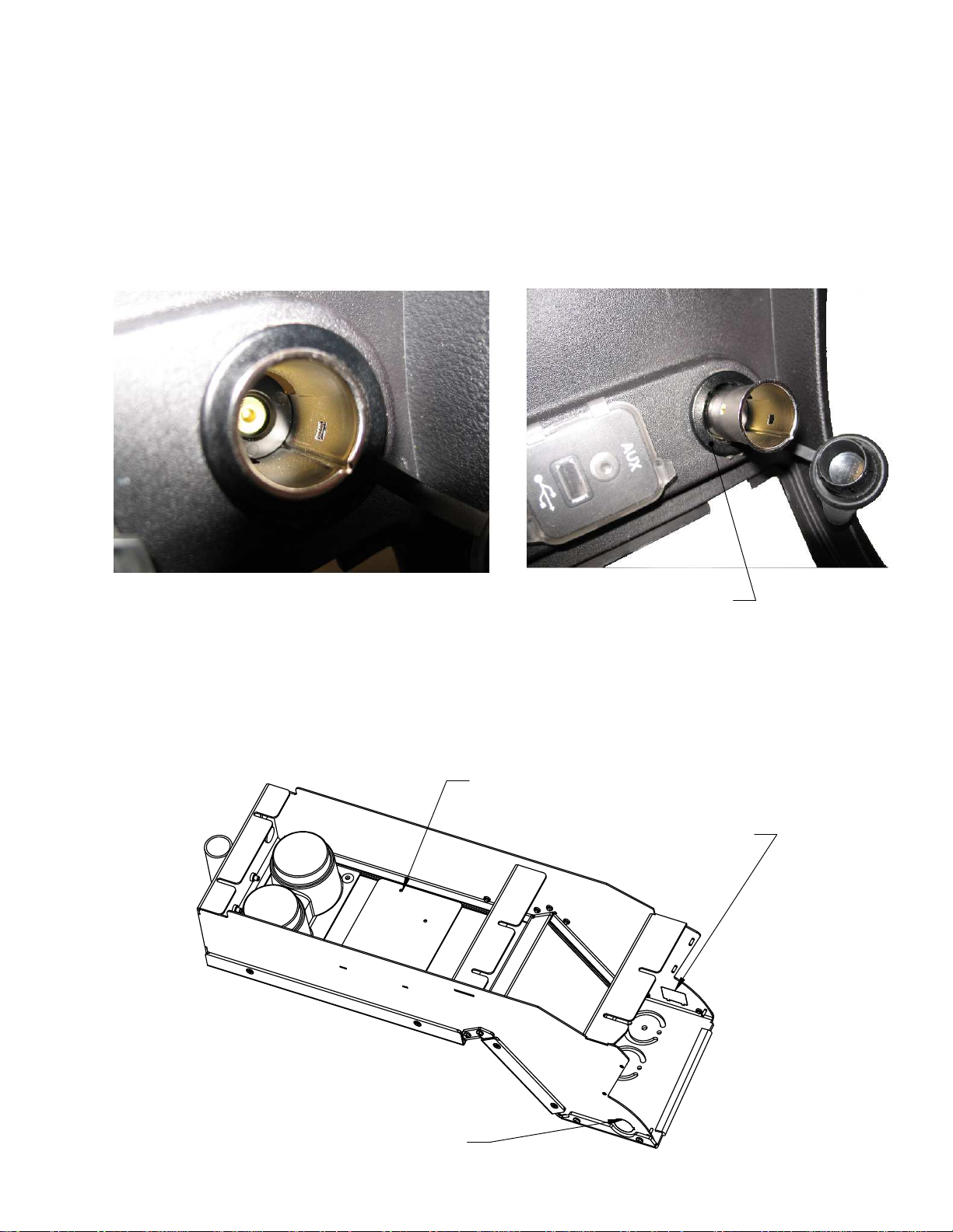
Installing factory 12v jack (optional)
1.Remove one of the 12v jacks from the factory console. This can be
accomplished by pressing the jack through from the back of the console.
2. Seperate the cap and ring from the 12v jack by depressing the tabs inside the
jack (Figure 1) then pressing the metal sleeve out of the plastic ring.
3. Remove the knockout from the left side of the console box
4. Install the ring and cap into the hole in the console box. Note orientation of
notch.
5. Install the 12v jack into the ring.
6. Connect harness from factory console
CAP AND RINGFig.1
Installing USB/MP3 Jack (optional)
1. Remove USB/MP3 box from factory console by depressing tabs on either side.
2. Remove the knockout from the right side of the console box.
3. Snap the USB/MP3 box into the opening in the console box.
YAW SENSOR PLATE
USB/MP3 KNOCKOUT
FACTORY 12v
JACK KNOCKOUT
Page 3

4. Install the low frequency antenea onto the YAW Sensor Plate using the provided
nylock nuts and #6-32 x 3/8 screws.
5. Connect the harness between the LFA, USB/MP3 box and 12v jack if used.
6. Place Spacer Bushings over rear studs on the transmission tunnel.
7. OPTIONAL Remove knockout on lower right hand side of the box and install
provided 12V jack. Install ground and power as required.
8. Slide console into vehicle. Downward pressure may be required on the front of the
box to allow it to slide under the instrument panel.
9. Secure console with OEM nut and provided M6 nuts, washers and lock washers on
front two brackets and provided 1/4-14 x 1.0" sheet metal screws at rear
attachement points. Some of the vinyl flooring may need to be cut to reveal the
rear mounting points.
10. Install the armrest (7160-0327, 7160-0347 & 7160-0354) into the tube and adjust to
desired height/orientation then tighten the bolt under the armrest. Note
Armrest is not included with 7160-0326 or 7160-0353 but can be ordered
seperately.
11. The cup holder (7160-0327) can be placed anywhere along the horizontal length
of the box. Note cup holder is not included with 7160-0326 or 7160-0353 but can
be ordered seperately.
12. Once the console box is secure, drive a self tapping screw (provided in hardware
bag) through the hole in the dash filler panels to secure them to the instrument
panel. Note Be careful not to over tighten the self tapping screw.
13. If required, the Top Plate and the Center Brace can be removed to allow easier
access for mounting and/or cable routing. If either item is removed Gamber Johnson recommends reinstalling the flat head screws with a drop of Blue 242
Loctite to prevent loosening.
LOW FREQUENCY ANTENEA
 Loading...