

Page 1
INSTALLATION INSTRUCTIONS
Product Revision Form
7160-0283
Recon CF19 Military Docking Station
Rev.A
Printing Spec: PS-001
This instruction sheet is for the following products:
7160-0283 = Rec on CF19 Mil itary Docking Station.
*These instructions are for the docking station only. For instructions on features, set-up and
operation of the CF19 computer, please refer to the manuals provided by Panasonic with the
computer.
INST-511
** This docking station is designed to be used with a variety of Gamber-Johnson mounting
systems. Installation instructions for other Gamber-Johnson products are provided with each
individual p r oduct.
IMPORTANT SAFETY INFORMATION for
I
NSTALLERS
Safety is dependent on the proper installation and servicing of this docking station. It is
important to read and follow all instructions before installing this product.
To properly install a Gamber-Johnson docking station you must have a good understanding
of automotive electrical procedures and systems, along with proficiency in the installation
and service of aftermarket vehicle equipment.
The re are no adju stments require d at any time of the electrical comp onents within the
docking station.
Product Mounting Disclaimer
Product Mounting Disclaimer
Gamber-Johnson is not liable under any theory of contract or tort law for any loss, damage, personal injury, special, incidental or consequential damages for personal injury or other damage
Gamber-Johnson is not liable under any theory of contract or tort law for any loss, damage, personal injury, special, incidental or consequential damages for personal injury or other damage
of any nature arising directly or indirectly as a result of the improper installation or use of its products in vehicle or any other application. In order to safely install and use Gamber-Johnson
of any nature arising directly or indirectly as a result of the improper installation or use of its products in vehicle or any other application. In order to safely install and use Gamber-Johnson
products full consideration of vehicle occupants, vehicle systems (i.e., the location of fuel lines, brakes lines, electrical, drive train or other systems), air-bags and other safety equipment is
products full consideration of vehicle occupants, vehicle systems (i.e., the location of fuel lines, brakes lines, electrical, drive train or other systems), air-bags and other safety equipment is
required. Gamber-Johnson specifically disclaims any responsibility for the improper use or installation of its products not consistent with the original vehicle manufactures specifications
required. Gamber-Johnson specifically disclaims any responsibility for the improper use or installation of its products not consistent with the original vehicle manufactures specifications
and recommendations, Gamber-Johnson product instruction sheets, or workmanship standards as endorsed through the Gamber-Johnson Certified Installer Program.
and recommendations, Gamber-Johnson product instruction sheets, or workmanship standards as endorsed through the Gamber-Johnson Certified Installer Program.
© copyright 2010 Gamber -Johnson, LLC
Opening the port replication housing will void the product warranty.
If y ou need assistance or have questions, call Gambe r-Johnson at 1-800-456-6868
Page 2

During Installation
zDO NOT connect this docking station to the vehicle battery until:
1. ALL other electrical connections are made
2. Mounting of ALL components is complete
3. VERIFICATION that no shorts exist in the entire system
zDO NOT install equipment or route wiring or chords in the deployme nt path of any
air bag.
zWhen drilling into the vehicle, DO make sure that both sides of the surface are
clear of anything that could be d amaged.
zIt is recommended to install a 32V - 10Amp in-line fuse connected as close to the
battery or power source as possible.
CAUTION: If w iring is shorted to the frame, high current conductors can cause
hazardous sparks resulting in electrical fires or flying molten metal.
fter Installation
A
zTest the docking station to ensure that it is working properly.
File these instructions in a safe place and refer to them when performing
maintenance or re-installing.
WARNING: Failure to follow all safety precautions and instructions may result
in property damage, serious injury or death.
PRE-INSTALLATION RECOMMENDATIONS
Conduct a "Bench Test"
Gamber-Johnson stron gly advises a "bench test" be conducted to verify that all electronic
and software issues are resolved prior to installation:
1. Make sure compute r is operational by itself.
2. Insert computer into docking station and verify that the computer is operating in the
dock.
3. Interconnect entire assembly and verify start-up of all components, including other
equipment (printers, modems, scanners, etc.).
*Gamber-Jo hnson also re commends positioning of all mounts and e quipment in the vehicle
prior to the actual install to verify that mounting locations are safe an d practical.
Page 3

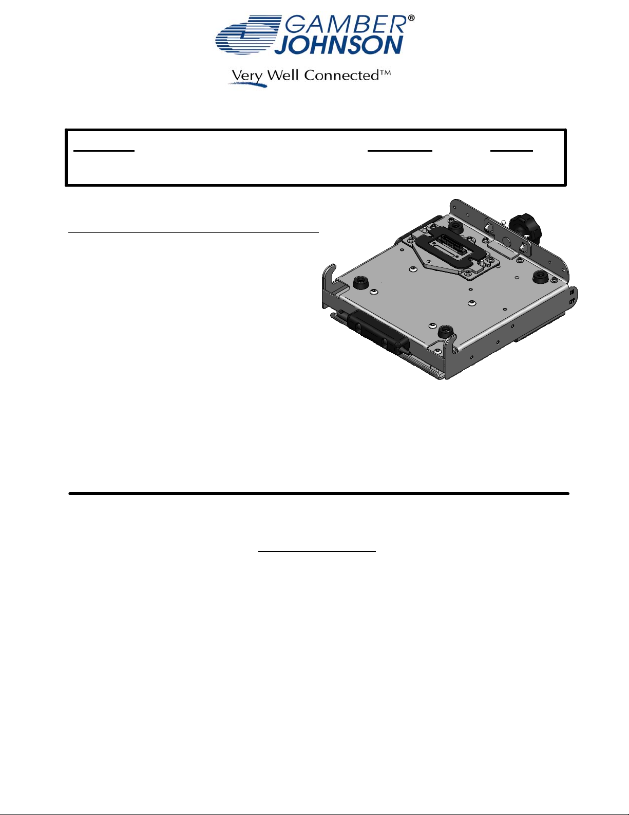
Mounting Hole Locations
1/4-20unc
Threaded Inserts
4.094
2.670
1.804
1.000
1.000
1.000
Hand Knob
Power Switch
Data Cable Port
(D38999 Shell Size 17)
Power Cable Port
(D38999 Shell Size 9)
Features
Stylus Holder
(Can be moved to
either side of the dock)
Protective
Connector Cover
Attach protective
connector cover
in this location when
a computer is mounted
in the dock
Ground Stud
Hasp for padlock with
9/32" dia. shackle
Page 4

Install ing the CF19 compute r into the dock
Step 1: Make sure the sliding door, located
on the bottom surface of the computer, has
been opened to expose the computers'
docking connector.
Step 2: Make sure no loose or foreign
objects are on the surface of the dock and
the connector cover is mounted in the
storage location on the side of the dock.
Step 3: Place the front edge of the co mputer
into th e dock. Two notches on the front
edge of the computer case will fit onto th e
two hooks along the front edge of the dock.
Step 4: Lower the back edge of the
computer down onto the docking connector.
Press down on the computer to compress
the connector gasket and align the rear
hooks with the notches in the back side of
the computer. Tighten the hand knob to
engage the rear hooks into the notches and
secure the computer down onto the dock.
Step 5: A padlock with a 9/32" diameter
shackle can be used to help secure the
computer to the docking station.
Page 5

Installing the CF19 Military Scre en Supports
Each screen support mounts to the outside
of the rear flange with (2) 8-32unc machine
screws and nylok nuts
Page 6

Data C a ble Pinout
Power Cable Pinout
PinoutTable
J1 Sig nal
4USBPWR2
5USBDM2
6USBDP2
7USBGND2
8USBPWR3
9USBDM3
16 USBDP3
15 USBGN D3
14 USBP WR4
13 USBDM4
12 USBDP4
11 USBGN D4
17 DCD1
18 RI1
19 OUT1
20 SIN1
21 RTS1
22 CTS1
23 DSR1
24 DTR1
31 GND
30 DD C2BC
47 TXD_PLUS
48 TX D_NEG
49 RXD_PLUS
50 RX D_NEG
51 A GND
52 HOUT
40 CRTR_GND
41 CRTR
42 CRTG_GND
43 CRTG
44 CRTB_GND
45 CRTB
46 GND
32 HSYNC
33 SYNC_GND
34 VSYN C
35 DD C2BD
36 +5VVIDEO
1+5V
2+5V
39 GND
25 GND
3NC
10 N C
26 N C
27 N C
28 N C
29 N C
37 N C
38 N C
53 N C
54 N C
55 N C
PinoutTable
J2 Signal
AReturn/GND
BNC
C+24Vdc
 Loading...