

Page 1
INSTALLATION INSTRUCTIONS
Product Revision Form
7160-0237
Rev. A
CONSOLE BOX - ERGO - HYBRID
The purpose of this instruction sheet is to illustrate the manufacturer's recommended method for installing the
MCS -Ergo-Hybrid conso le box. MCS-Ergo-Hybrid console box is a discrete solution for mountin g various mobile
communication control heads and r adios. Included with the MCS-Ergo-Hybrid console box is one set of short
Faceplate Vertical O ffsets. Due to a shallow depth in the front end of the console box, these Faceplate Vertical Offsets
must be used in place of the Vertical Offsets that come with G amber-Johnson Faceplate Kits (see INS T-3 included).
INST-471
Tools Needed
7/16 wrenc h or so ck et
5/16 hex head wrench
#2 Philips head screwdriver
Installation
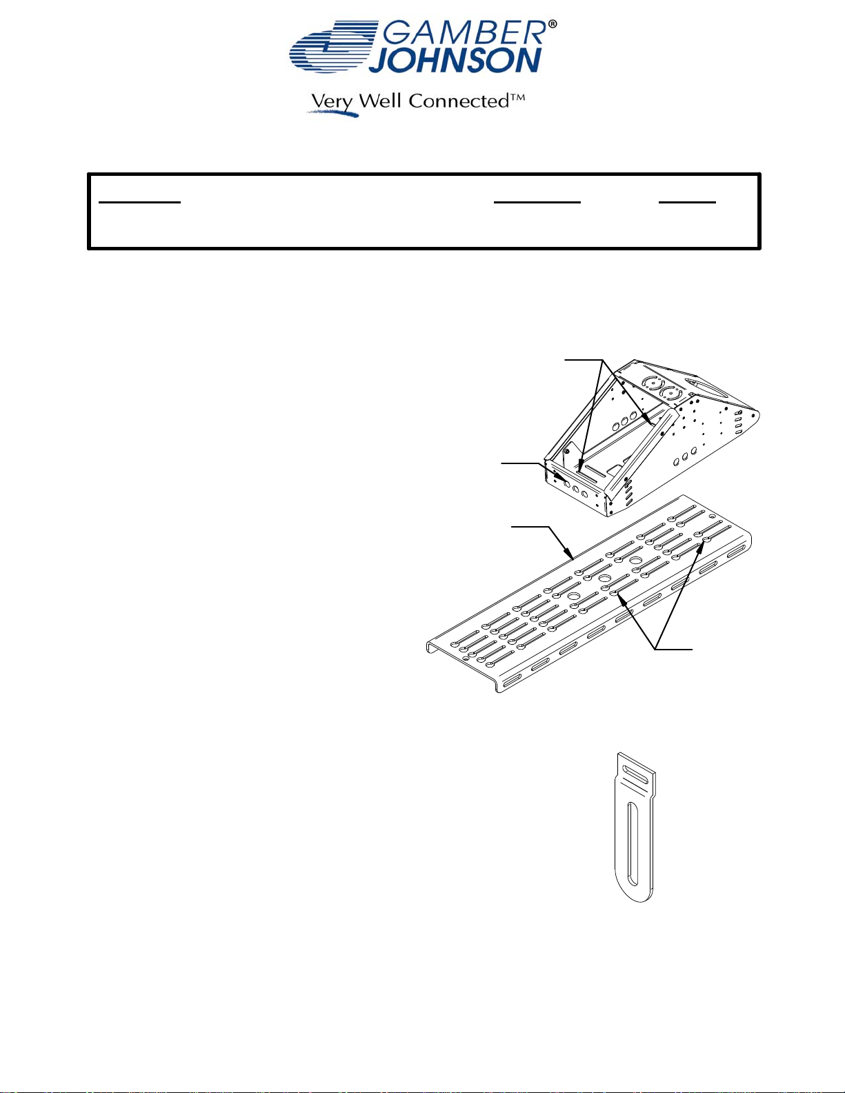
1. When installing the MCS-Ergo-Hybrid console box
onto a Gamber-Johnson MCS Top Plate, insert and
loosely assemble four 1/4-20 carriage bolts, four 1/4"
Dia. washers, four 1/4" lock washers, and four 1/4-20
hex nuts about the desired mounting slots in the
bottom of the box (see Fig u re 1 ).
from the front of the box will align with the key holes in
the Top Plate. Slots two and four will also al ign with
the key holes in the Top Plate.
carriage bolts below the box.
2. Insert the four heads of the carriage bolts into the
desired corresponding key holes (see Figure 1 ) on
the MCS-Top Plate until the bolt heads drop below
the Top Plate. Place box in desired position and
tighten hardware.
3. Due to the shallow depth of the front face, as
compared to the MCS-Epic console box series, it is
necessary to replace the standard Vertical Offsets with
a set of shorter Vertical Offsets (1 set is included with
the MCS -Ergo -Hy brid c onsole box). The radio/radio
head in the lowest position on the box will require the
Short Vertical Offset. Follow instruction sheet INST-3
for assembly and installation instructions, substituting
the short Faceplate Vertical O ffsets (se eFigure 2) with
the Vertical Offsets that come with Gamber-Johnson
Facplate Kits.
Slots one and three
Orient the head of the
Mounting Slots
1 & 3
Front Face
MCS Top Plate
Key Holes
Figure 1: Align mounting slots with key holes.
Figure 2: Short Vertical Offset
Product Mounting Disclaimer
Product Mounting Disclaimer
Gamber-Johnson is not liable under any theory of contract or tort law for any loss, damage, personal injury, special, incidental or consequential damages for personal injury or other damage
Gamber-Johnson is not liable under any theory of contract or tort law for any loss, damage, personal injury, special, incidental or consequential damages for personal injury or other damage
of any nature arising directly or indirectly as a result of the improper installation or use of its products in vehicle or any other application. In order to safely install and use Gamber-Johnson
of any nature arising directly or indirectly as a result of the improper installation or use of its products in vehicle or any other application. In order to safely install and use Gamber-Johnson
products full consideration of vehicle occupants, vehicle systems (i.e., the location of fuel lines, brakes lines, electrical, drive train or other systems), air-bags and other safety equipment is
products full consideration of vehicle occupants, vehicle systems (i.e., the location of fuel lines, brakes lines, electrical, drive train or other systems), air-bags and other safety equipment is
required. Gamber-Johnson specifically disclaims any responsibility for the improper use or installation of its products not consistent with the original vehicle manufactures specifications
required. Gamber-Johnson specifically disclaims any responsibility for the improper use or installation of its products not consistent with the original vehicle manufactures specifications
and recommendations, Gamber-Johnson product instruction sheets, or workmanship standards as endorsed through the Gamber-Johnson Certified Installer Program.
and recommendations, Gamber-Johnson product instruction sheets, or workmanship standards as endorsed through the Gamber-Johnson Certified Installer Program.
© copyright 2009 Gamber-Johnson, LLC
If y ou need assistance or have questions, call Gambe r-Johnson at 1-800-456-6868
SHEET 1 OF 3
Page 2
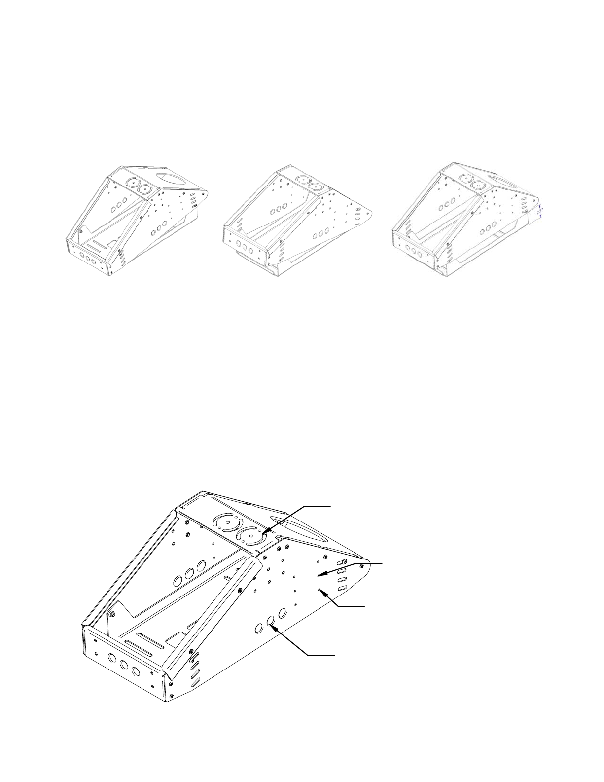
Adjustment
The MCS-Ergo-Hybrid console box is designed to allow adjustment of the front to back angle for the system. The box
can be tilt towards the front or back by up to eight degrees in each direction (Figure 3a and 3b).
The MCS-Ergo-Hybrid console box is designed to allow adjustment of the height of the system by up to 2.37-inches
(Figure 3c).
To adjust the tilt or height of the console box remove the appropriate socket head cap screws from each side of the bo x
and tilt or lift the box into the de sired position. Secure the box position with the socket head cap screws that were
removed.
Forward Tilt
(a)
Rear Tilt
(b)
Figure 3: Tilt adjustment and height adjustment
Horizontal
(c)
Mounting Features
Motion Atta chments
The MCS-Ergo-Hybrid console box will allow a user to mount any Gamber Johnson motion attachment to the top of the
box. It is recommended that all clev is attachments be mounted to the right most circle pattern to prevent interference
with the clevis knob and top of the console.
Electronics
The MCS-Ergo-Hybrid console box will allow a user to mount the Lind Ruggedized Shut Down Timer (Gamber PN
13791) or the 6 Circuit Power Distribution Block (Gamber PN 7160-0110) without drilling holes.
The MCS-Ergo-Hybrid console box has nine knockout locations to allow the use of several 12V automotive power
sockets (Gamber PN 7160-0063).
Clevis Mount Location
Lind Ruggedized Shut Down
Timer Two Hole Pattern
6 Circuit Power Distribution
Block Four Hole Pattern
12V Automotive Power Socket
Mount Location
Figure 4: Motion Attachment and Electronics mo unting points
SHEET 2 OF 3
Page 3

Mounting Features Cont.
MCS Accessories
The front of the MCS-Ergo-Hybrid console bo x allows the attachment of any Gamber Johnson cup holder (MC S-CUP,
MCS-CUP2, MCS-CUPHOLD2) or extension box (7160-0028). The lower two threaded inserts are used for a
horizontal setup. The upper two threaded inserts are used for a forward tilt setup.
Cup Holder or Extension Box Mount Location
Foward Tilt Setup
Cup Holder or Extension Box Mount Location
Horizontal Setup
Figure 5: MCS Accessory mounting points
Assembling the MCS-MICPLT
The MCS-MICPLT is a kit that allows a radio microphone to be mounted in the same fashion as all Gamber Johnson
Faceplates. The mic clip itself is not provided with the MCS-MICPLT kit as it is standard that a mic clip is shipped with
most communication devices that use a microphone. Assemble as illustrated in Figure 6.
It is recommended that if using the MCS-MICPLT kit to place the finished assembly in the lowest position on the
MCS-Ergo-Hybrid console box. By assembling the kit in this fashion you be able to avoid using the short Faceplate
Vertical Offset (Figu r e 2 ).
Figure 6: MCS-MICPLT kit assembly
Pole Mount
The back of the MCS-Ergo-Hybrid console box will allow the use of a Lower Tube (DS-Lower-7, DS-Lower-9, or
DS-Lower-13) as an alternate mounting location.
Figure 7: Lower Tube mounted in the back of the MCS-Ergo-Hybrid console box.
SHEET 3 OF 3
Page 4

INSTALLATION INSTRUCTIONS
Product Date Form #
Faceplates 02/23/01 INST3
ASSEMBLING MCS FACEPLATES: (Refer to figure 1)
1. Check that the following pieces are present:
Dual lock fastener (supplied w/console box)
(1) faceplate vertical offset
(1) faceplate top bracket
(1) flat washer #6
(1) 6-32 nut
2. For each faceplate, slide the faceplate vertical offset
(item 1) on the stud in faceplate top bracket (item 2).
Add flat washer (item 3) and hex nut (item 4). Remove
the extra strips of dual lock fastener pressed onto each
console box under holddown rails, cut to same length as
each faceplate, remove protective film covering the
adhesive strip and apply to top bracket as shown.
3. If the faceplates are being mounted in an older style MCS Console Box (those with threaded inserts on the
top surface of the side panels/holddown screws passing through slots in existing face plates or blank
panels), DO NOT attach the strip of dual lock fastener on each faceplate as described above. When
installing faceplates into these MCS Console Boxes, mark any that cover the threaded inserts and drill a .312
diameter clearance hole as shown in Figure 1.
ASSEMBLING MCS FACEPLATES TO CONTROL HEADS AND INSTALLING IN MCS CONSOLE BOXES (Refer to figures
2 & 3).
1. Install the faceplates on each control head as shown in figure 2. Adjust the faceplates so the mounting
holes in the sides of the control head line up in the slots of the faceplate vertical offsets and so the desired
amount of the control head will extend from the console. Make sure to allow enough room underneath for
any connectors that may be required. Test the fit of each control head, the tallest heads may need to be
installed near the higher end of the console.
2. Arrange the control heads in the console box as desired. Blank panels of various sizes have been provided to
act as spacers between each control head, if needed. Secure in place by attaching a piece of dual lock
fastener to each end of the blank panel and then pressing the strips of dual lock fastener on the faceplates,
blank panels and console box together.
3. Attach the MCS Console Box holddowns to the sides of the console box and over faceplates with (6) 10-32 x
.38 Phillips head machine screws.
 Loading...