

Page 1
INSTALLATION INSTRUCTIONS
Product Revision Form
PANASONIC CF19 DOCKING STATIONS,
CRADLE and ACCESSORIES
7160-0207: Docking Station (NO/RF)
7160-0207-02: Docking Station (DUAL/RF)
7160-0264-00 (-P): MK4 Docking Station (NO/RF)
7160-0264-02 (-P): MK4 Docking Station (DUAL/RF)
7160-0264-03 (-P): MK4 Docking Station w/Power Adapter (NO/RF)
7160-0264-04 (-P): MK4 Docking Station w/Power Adapter (DUAL/RF)
7160-0264-05: Cradle CF19 MK4
Rev. H
7160-0215: LED Assembly
7160-0049: CF19 Screen Support
7160-0073: CF19 Wedge
Printing Spec: PS-001
7160-0207 & 7160-0207-02 Docking Stations are compatible with all CF19 & CF18 computers.
7160-0264-00 (-P), 7160-0264-02 (-P), 7160-0264-03 (-P) & 7160-0264-04 (-P) Docking Stations
(Identified byToughbook Certified "Red Check" Label) are compatible only with CF19 MK4
Computers. MK4 Computers are identified by a letter "R" or higher in the computers model
number (i.e. CF-19R...)
7160-0264-05 Cradle CF19 MK4, and all accessories, are compatible with all CF19 Computers.
Panasonic recommends using a Lind Auto Adapter to power the docking station. It can be ordered from
Gamber-Johnson (Item No. 11798).
INST-372
For instructions on the features, setup and operation of the CF19 computer, refer to the manuals
supplied by Panasonic with the computer.
No adjustments of the electrical components within the electrical enclosure are required. Opening
the enclosure (except to install the Power Cable) will break a seal and void the product warranty.
Conducting a "bench test", (the assembly, interconnection and start-up of all components:
Computer, Docking Station and any customer supplied equipment: printers, modems, scanners, etc.)
is strongly advised to verify all electronic and software issues are resolved.
Suggested flow of work is to:
1. Install and verify the computer is operational.
2. Add customer supplied equipment (printers, modems, scanner etc.)
If installing inside a vehicle, positioning of all mounts and equipment in the vehicle before the actual
install is also recommended to verify that mounting locations are practical.
Drivers: If needed, the software driver for this product can be downloaded from Panasonic's Support
Page: http://panasonic.com/business/toughbook/computer-support-search-downloads.asp
Product Mounting Disclaimer
Gamber-Johnson is not liable under any theory of contract or tort law for any loss, damage, personal injury, special, incidental or consequential damages for personal injury or other damage
of any nature arising directly or indirectly as a result of the improper installation or use of its products in vehicle or any other application. In order to safely install and use Gamber-Johnson
products full consideration of vehicle occupants, vehicle systems (i.e., the location of fuel lines, brakes lines, electrical, drive train or other systems), air-bags and other safety equipment is
required. Gamber-Johnson specifically disclaims any responsibility for the improper use or installation of its products not consistent with the original vehicle manufactures specifications
and recommendations, Gamber-Johnson product instruction sheets, or workmanship standards as endorsed through the Gamber-Johnson Certified Installer Program.
© copyright 2011 Gamber-Johnson, LLC
If you need assistance or have questions, call Gamber-Johnson at 1-800-456-6868
1 0F 7
Page 2
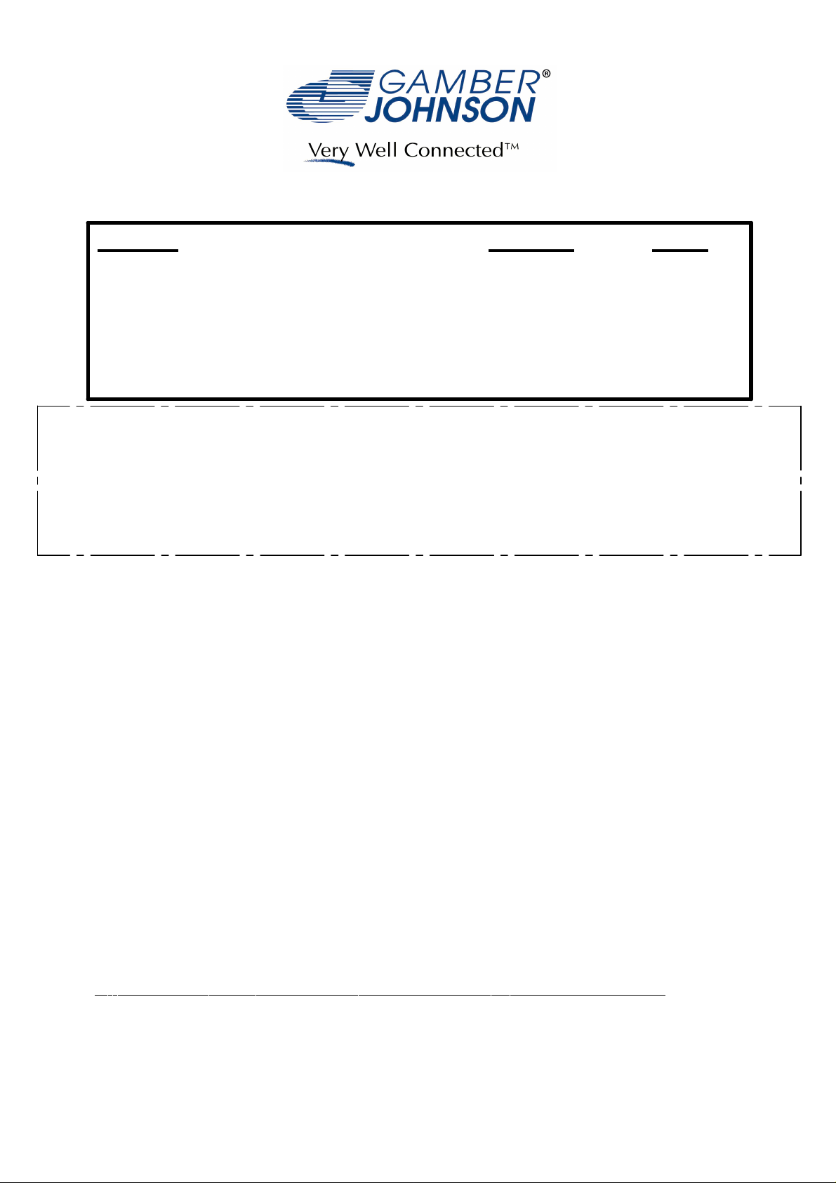
PANASONIC CF19 DOCK
Top View
External
Antenna
Connectors
Front
Alignment
Guide
Multi I/O
Connector
Vibration
Damper
Alignment
Pin
Vibration
Damper
Vibration
Damper
Front
Alignment
Guide
Toughbook Certified Label
See Sheet 1 for computer
compatibilitty statement
Latch
Mechanism
Latch
Security Lock
Vibration
Damper
USB Port
Power ON LED
Alignment
Pin
RJ45
Connection
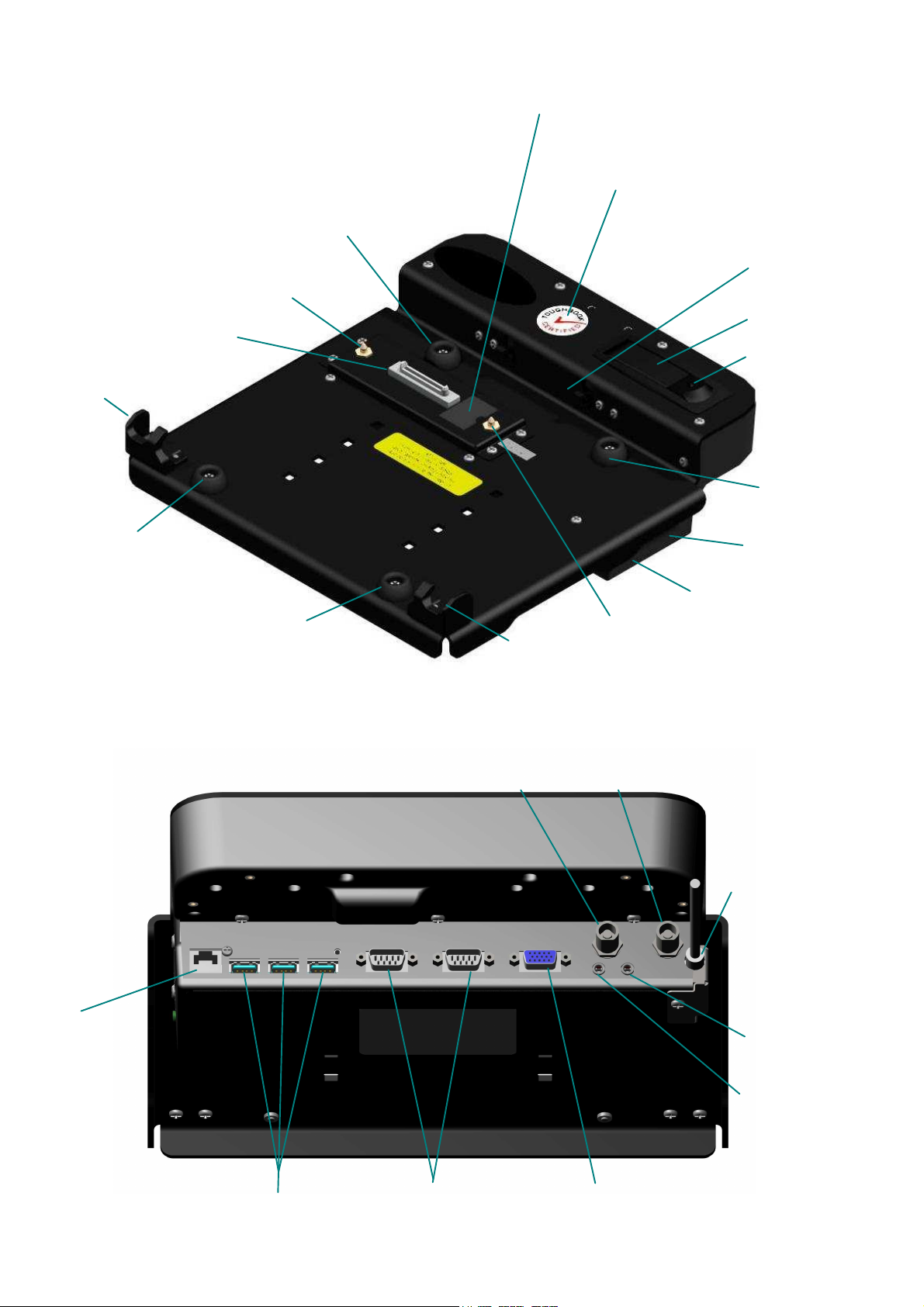
Back View
WLAN/GPS
Antenna
Connector
WWAN
Antenna
Connector
DC In
External
Microphone
External
Speakers or
Headphones
USB Port
Serial
Connection
Video
Connection
2 0F 7
Page 3
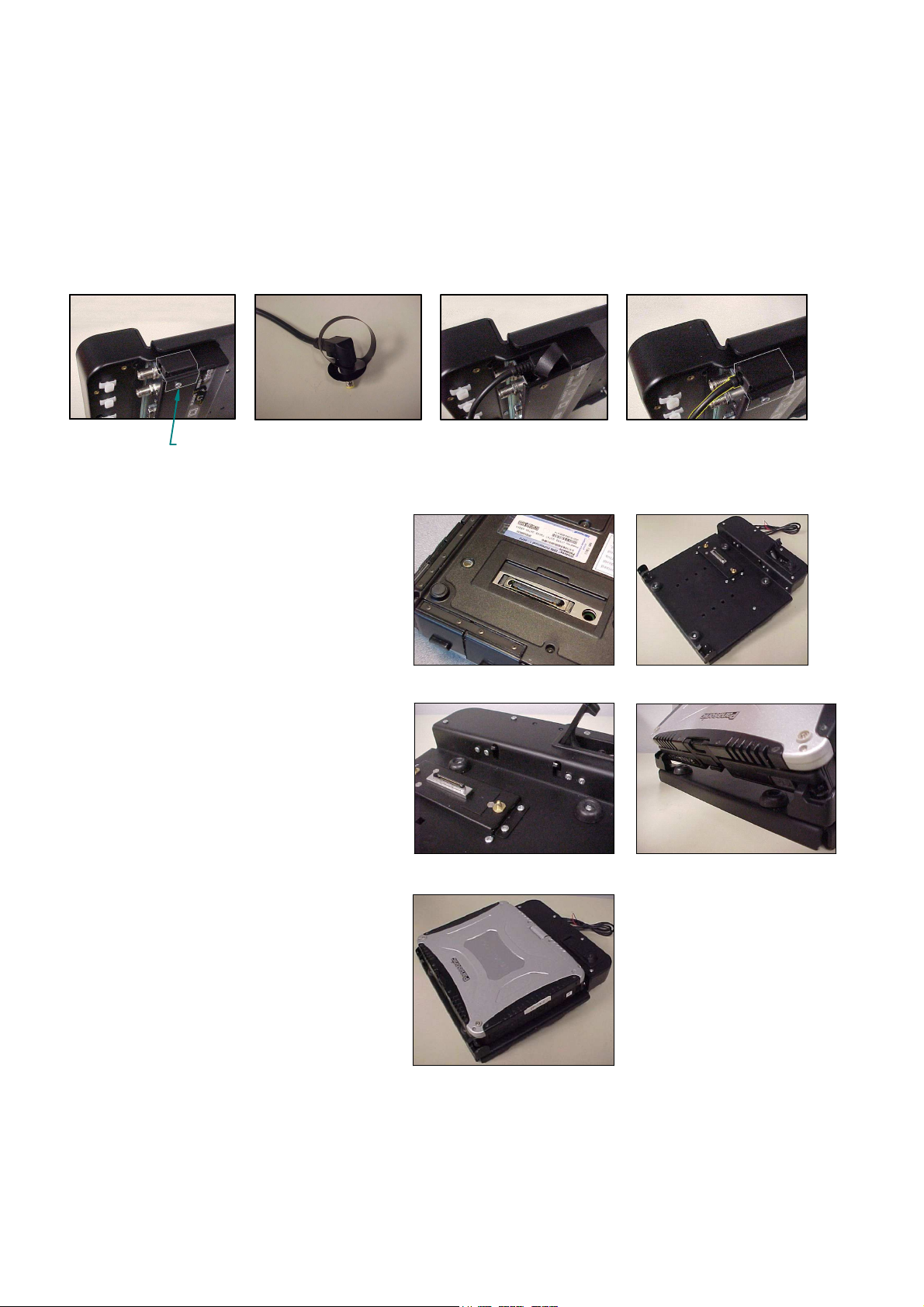
Installation of the Power Jack:
Remove the #6-32unc x .1/4" long scew that attaches the Power Cable Cover to the outside of
the dock (fig 1). Attach the Power Cable Pull Strap (located in hardware bag) to the power
jack (fig 2). Plug the power jack into the input jack located on the port replicator board and
tuck the pull strap into the electrical box (fig 3). Replace the Power Cable Cover to hold the
power jack in place (fig 4).
fig 1
Installing CF19 Computer into the Dock
Step 1: Make sure the sliding door, located
on the bottom surface of the computer, has
been opened to expose the computers'
docking connector (fig 5). Make sure no
loose or foreign objects are on the surface
of the dock (fig 6).
Step 2: Unlock the latch if locked. Depress
the latch button to release the rear hooks
(fig7).
Step 3: Place the front edge of the computer
into the dock. Two notches on the front
edge of the computer case will fit onto the
two hooks along the front edge of the dock
(fig 8). Lower the back edge of the
computer down onto the docking connector.
Press down on the computer making sure
the computer case is flat in the dock.
Depress the latch to secure the computer.
Lock the latch if necessary (fig 9).
Remove
#6-32 x 1/4-in screw
& power cable cover
fig 2
fig 3
fig 5 fig 6
fig 7 fig 8
fig 4
fig 9
3 0F 7
Page 4

ReLocating Computer Carrying Strap
The CF19 computer is supplied, from Panasonic, with a carrying strap attached to the back
edge of the computer case.
The computer can be installed into the dock with the strap attached to the back or front edge,
but the strap will need to be unhooked when installed on the front of the comptuer, allowing
each end of the strap to hang down over the sides of the dock.
If the strap is not unhooked it will interfere with the docks' latching mechanism.
Important:
If the strap is relocated to the front or side edges, position the strap ends as shown .
The rings on the ends of the straps must be positioned away from the front retainers.
If the rings are incorrectly attached and touch the front retainers, the computer will not dock
properly.
Strap Ring attached away from Front Retainer
Strap Ring attached away from Front Retainer
Front Retainer
Front Retainer
Strap attached to back of computer will lay over the
top of the dock.
4 0F 7
Page 5

Cable Ties
Cables are attached to ports on the back of the
dock. Cable ties and cable tie holders are
provided to secure the cables to the dock. Press
the cable tie holder into the mounting holes on
the dock. Insert the cable tie through the tie
holder and tighten the cable tie around the
cables as needed.
Cable Ties
DOCKING INDICATOR LED
With computer installed in the dock, the Docking Indicator LED, located on the right side of the dock,
can be used as a troubleshooting tool.
GREEN: All ports are ready to use.
ORANGE: USB port and LAN port do not function, external power is not connected.
RED: PC is not supported or connection is not made.
RED (BLINKING): Error has occured in the firmware. Stop using at once and contact Panasonic
Technical Support.
NOT LIT: PC not installed or PC is OFF, Standby or Hibernation.
Vehicle Mounted Docks
CF19 vehicle docks and cradle are designed to be used with Gamber-Johnsons' motion
attachments, poles and vehicle bases.
See below for mounting dock to DS, MCS or 0-90 Clevis with (4) .25-20 x .75 long carriage bolts.
.25-20 x .75 Carriage Bolt
0-90 CLEVIS
DS or MCS
CLEVIS
.25 Flat Washers
.25-20 Nuts
.25 Flat Washers
.25-20 Nuts
5 0F 7
Page 6

CF19 Accessories
Screen Support
7160-0049: CF19 Screen Support
Use two #8-32 x .38 long socket head screws and
two #8 flat washers to attach the screen support to
the back side of the CF19 Dock as shown.
7160-0073: Work Table Wedge
The CF19 work table wedge has rubber pads to provide a mobile slip free mounting surface. Four .281
square holes on the bottom surface allow mounting the work table wedge permanently to a surface if
required. See drawing for mounting hole location.
#8-32 X .38 Screws
and Flat Washers
4X .281 q Holes
.25-20 x .75 HHCS
.31
7.19
.519.41
(Mounting Hole Location)
6 0F 7
Page 7

7160-0215: LED Assembly
Position the LED assembly over two holes in the
back cover, and attach using the #6-32unc x .38
screws that were provided with the LED assembly.
The LED is powered using the red and black wires
on the back of the light base. The LED Assembly
is designed to operate on 12volts DC.
LED Assembly
Activation Button
In a negative ground vehicle:
Connect the RED wire to the positive pole of the
vehicle battery or power distribution box. It is
recommended that a user-supplied fuse holder and
1 amp fuse be installed on red the wire. Connect
the Black wire to a suitable chassis GROUND or
the NEGATIVE pole of the battery.
Turn on the LED by pressing the Activation
Button on the head of the LED Assembly.
#6-32 x .38 Screws
The LED has three light options: White,
Red and White/Red. Press the Activation
Button to toggle through the options.
Hold the Activation Button down for
approximately one second to turn the LED
off.
7 0F 7
 Loading...