

Page 1
INSTALLATION AND SERVICING
INSTRUCTIONS
AND
USER'S INFORMATION MANUAL
**INSTALLER — AFFIX THIS INSTRUCTION
PACKET ADJACENT TO THE FURNACE.
**HOMEOWNER — RETAIN THESE
INSTRUCTIONS FOR FUTURE REFERENCE.
INSTRUCTIONS D'ENTRETIEN ET
INSTALLATION
ET
MANUEL DE L'USAGER
**INSTALLATEUR -- PLACEZ LA POCHETTE
D'INSTRUCTIONS À COTÉ DU GÉNÉRATEUR
D'AIR CHAUD.
**PROPRIÉTAIRE -- CONSERVEZ CES
INSTRUCTIONS POUR Y RÉFÉRER PLUS TARD.
20536912
LITERATURE BOOKLET NO. 20557401
ISSUE 0442
Page 2
Owner Record
Furnace Model # Serial # Installation Date
INSTALLED BY:
Dealer
Address
Telephone # License #
Contact Person
Other Equipment Installed:
Equipment Type
Model # Serial # Installation Date
Equipment Type
Model # Serial # Installation Date
Equipment Type
Model # Serial # Installation Date
WHEN FRENCH IS REQUIRED!
ATTENTION: MR. INSTALLER OR HOMEOWNER
TO OBTAIN INSTALLATION INSTRUCTIONS, USER'S INFORMATION MANUAL AND FURNACE
MARKINGS IN FRENCH CONSULT WITH YOUR DEALER OR LOCAL DISTRIBUTOR:
HAVE AVAILABLE THE MODEL NO. AND SERIAL NO. LOCATED ON THE UNIT RATING PLATE TO
INSURE THE CORRECT FRENCH INSTRUCTION PACKET.
POUR OBTENIR DE LA DOCUMENTATION EN FRANÇAIS!
À L'ATTENTION DE L'INSTALLATEUR OU DU PROPRIÉTAIRE
POUR OBTENIR LES INSTRUCTIONS D'INSTALLATION, LE MANUEL DE L'USAGER ET LES
MARQUAGES EN FRANÇAIS, CONSULTEZ VOTRE MARCHAND OU LE DISTRIBUTEUR DE VOTRE RÉGION:
AYEZ EN MAIN LE MODELE ET LE NUMÉRO DE SÉRIE INDIQUÉS SUR LA PLAQUE SIGNALÉTIQUE
DE L'APPAREIL POUR OBTENIR LA POCHETTE D'INSTRUCTIONS EN FRANÇAIS APPROPRIÉE.
Page 3
USER'S INFORMATION MANUAL
Gas-Fired Furnace
READ ALL INSTRUCTIONS IN THIS MANUAL AND RETAIN THIS AND ALL ADDITIONAL INSTRUCTIONS FOR FUTURE REFERENCE.
Congratulations...
...you have one of the most modern gas furnaces made.
Your unit has been carefully selected to keep you warm
and comfortable during the winter months. It will deliver
superb performance with only minimal help from you.
To keep your operating costs low and to eliminate
unnecessary service calls, we have provided a few
guidelines. These guidelines will help you understand
how your gas furnace operates and how to maintain it so
you can get years of safe and dependable service.
FIRE OR EXPLOSION HAZARD
Failure to follow safety warnings exactly
could result in serious injury death or
property damage.
— Do not store or use gasoline or other
flammable vapors and liquids in the
vicinity of this or any other appliance.
— What to do if you smell gas:
GAMA Certified
The Gas Appliance Manufacturers Association (GAMA)
symbol verifies that Annual Fuel Utilization Efficiency
(AFUE) ratings for our gas furnaces have been derived
from U.S. Government standard tests.
CSA International Design Certified
The CSA International symbols on each nameplate is
your assurance that your furnace design meets nationally
recognized standards for safety and performance.
• Do not try to light any appliance.
• Do not touch any electrical switch; do
not use any phone in your building.
• Leave the building immediately.
• Immediately call your gas supplier from
a neighbor's phone. Follow the gas
supplier's instructions.
• If you cannot reach your gas supplier,
call the fire department.
— Installation and service must be
performed by a qualified installer,
service agency or the gas supplier.
TABLE OF CONTENTS
SAFETY . . . . . . . . . . . . . . . . . . . . . . . . . . 2
OPERATING YOUR FURNACE . . . . . . . . . . . 2
Lighting Instructions . . . . . . . . . . . . . . . . . 2
Temperature Control . . . . . . . . . . . . . . . . . 3
Fan Operation . . . . . . . . . . . . . . . . . . . . . 3
MAINTENANCE OF YOUR FURNACE . . . . . . 4
Periodic Inspections . . . . . . . . . . . . . . . . . 4
Cleaning/Replacing the Filter . . . . . . . . . . . 5
Parts Replacement Guide . . . . . . . . . . . . . 6
20558901 Issue 0442 Page 1 of 6
Page 4
For your safety Read before operating
Here are a few "Do's and Don'ts"
• Do become familiar with the User's Instruction
Manual and Installation Instructions.
Do not use this furnace if any part has been under water.
A flood-damaged furnace is extremely dangerous.
Attempts to use the furnace can result in fire or explosion.
A qualified service agency should be contacted to inspect
the furnace and to replace all gas controls, control system
parts, electrical parts that have been wet or the furnace
if deemed necessary.
• Do check to see that your home has adequate
insulation, weatherstripping, caulking, and storm
windows. Elimination of infiltration of outside air and
drafts can save up to 40% of your fuel bill.
• Do consider adding a humidifier to your heating
system. Higher indoor humidity slows evaporation
of perspiration, making the home seem warmer.
• Don't waste fuel by setting your thermostat too
high. Energy conservation experts recommend a
daytime thermostat setting of 68°F, with a lower
setting at night.
• Don't turn off the furnace when you expect to be
away for more than a day. Instead, lower the
thermostat setting a few degrees. You can then
restore normal comfort level quickly and save fuel
too.
• Don't block registers with furniture.
• Don't put a lamp, TV, or radio too near your
thermostat. This will cause it to give a false reading.
The furnace area must be kept clear and free of
combustible materials, gasoline, and other
flammable vapors and liquids. Failure to do so
could cause actions that may result in property
damage, personal injury, or loss of life.
Operating Your Furnace
Lighting Instructions
1. STOP! Read the previous safety information.
2. Set the thermostat to the lowest setting.
3. Turn off all electric power to the furnace.
4. Remove the burner compartment access panel.
5. This appliance is equipped with an automatic ignition.
device. Do not try to light the burners by hand.
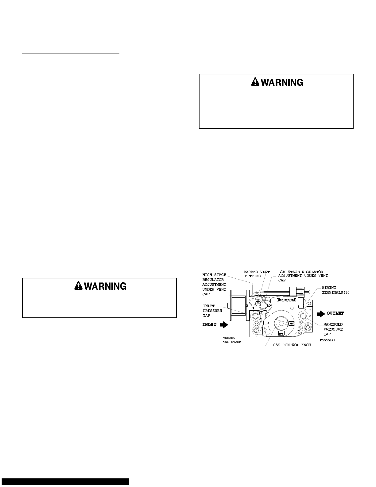
6. Move the gas control knob to "OFF" (see Figure 1).
If you do not follow these instructions exactly, a fire
or explosion may result, causing property damage,
personal injury, or loss of life.
These furnaces are equipped with an ignition device
which automatically lights the burners. Do not try to
light the burners by hand.
Before operating, smell around the furnace area for gas.
Be sure to smell next to the floor because some gas is
heavier than air and will settle to the lowest point. Refer
to "What to do if you smell gas" on page 1 if the odor
of gas is present.
Use only your hand to adjust the gas control switch;
never use tools. If the switch will not move by hand,
don't try to repair it, call a qualified service technician.
Force or attempted repair may result in a fire or
explosion.
20558901 Issue 0442 Page 2 of 6
7. Wait 5 minutes to clear out any gas, then smell for
gas (including at the bottom of the unit near the
ground). If you smell gas, stop and follow the
directions in "What to do if you smell gas" on page
1. If you don't smell gas, continue to next step.
8. Move the gas control knob to "ON".
9. Replace the burner compartment access panel.
10. Turn on all electric power to the furnace.
Figure 1
Page 5
11. Set the thermostat to the desired setting.
12. If the furnace will not operate, follow the instructions
in "To Turn Off Gas to Furnace" and call your
service technician or gas supplier.
To Turn Off Gas to Furnace
1. Set the thermostat to the lowest setting.
Fan Operation
You may wish to increase your comfort by setting your
system for continuous air circulation of the indoor air.
The fan switch on the thermostat permits you to do this.
With the switch in the "ON" position the fan will operate
continuously. "AUTO" position gives fan operation only
when the unit is in either heating or cooling.
2. Turn off all electric power to the furnace if service is
to be performed.
3. Remove the burner compartment access panel.
4. Move the gas control switch to "OFF" (see Figure 1).
Do not force.
5. Replace the burner compartment access panel.
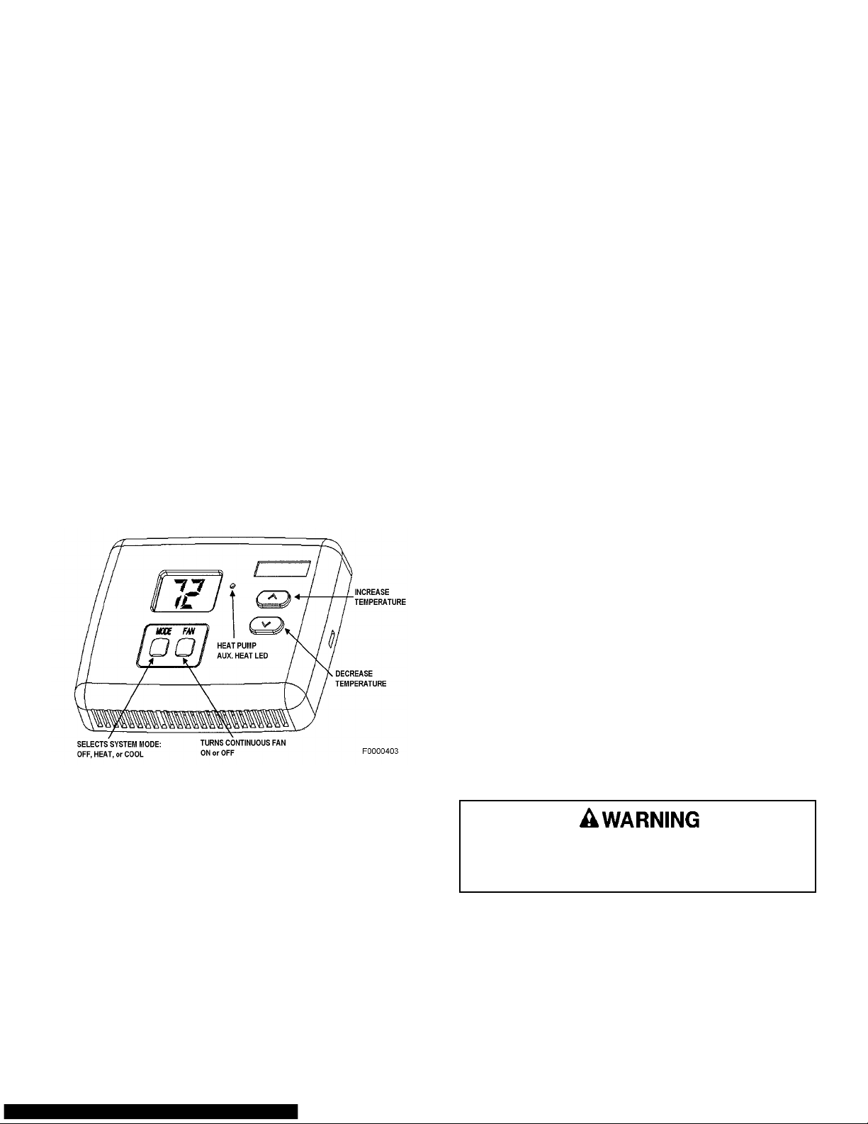
Temperature Control
There are many types and styles of thermostats. Yours
may look different from the one pictured in Figure 2,
depending on the type of thermostat and whether cooling
was installed with the system. However, almost all
thermostats perform the same basic functions described
in the following section.
What to do if your unit is not heating properly
If your furnace is operating but fails to provide complete
comfort, check the following before calling for service:
1. Be sure the thermostat setting is correct.
2. Check to see if the filter is clean.
3. Be sure air can circulate freely throughout your home.
Do not block supply registers or return grilles with
furniture or rugs.
And if you also have cooling...
4. Keep surface of the outdoor coil free from dirt, lint,
paper, or leaves.
5. Check and clean indoor coil, if necessary. (This
check should be made at the start of each cooling
season by your service technician).
What to do if your unit fails to operate
1. Be sure the main switch that supplies power to the
furnace is in the "ON" position.
2. Replace any burned-out fuses or reset circuit
breakers.
3. Be sure the thermostat is properly set.
4. If the furnace still does not start, call your service
Figure 2
Thermostat Operation
There are four (4) buttons on the thermostat (see Figure
2). One button controls the heating and cooling (if
applicable) functions. Another button is for "FAN"
technician.
Should the gas supply fail to shut off or if
overheating occurs, shut off the gas valve to the
furnace before shutting off the electrical supply.
operation, either continuous or automatic. The remaining
two buttons set the temperature range for the heating
temperature and the cooling temperature desired.
To put the system into operation, push the button to
either "HEAT" or "COOL" position. After you have chosen
the type of operation you desire, set the thermostat to
the temperature you would like the system to maintain.
20558901 Issue 0442 Page 3 of 6
Page 6
Maintenance Of Your Furnace
Always shut off all power to the unit before
attempting any of the following maintenance
procedures. Failure to do so may result in personal
injury.
There are routine maintenance steps you should take to
keep your furnace operating efficiently. This maintenance
will assure longer life, lower operating costs, and fewer
service calls. In addition to the maintenance procedures
listed in this manual, there are also other service and
maintenance procedures that require the skills of a
service person who has specialized tools and training.
(See "Servicing the Furnace" section of the Installation
and Servicing part of this booklet.) Personal injury can
result if you are not qualified to do this work. Please
call your dealer when service is needed.
Cleaning
The cabinet of the furnace can be cleaned with soap and
water. Grease spots can be removed with a household
cleaning agent. The cabinet can be kept attractive by
polishing with automotive wax at least twice a year.
Installations Around Insulation
Insulating materials may be combustible. Therefore, a
furnace installed in an attic or other insulated space must
be kept free and clear of insulating materials. Make sure
to examine the furnace area when the furnace is installed
or additional insulation has been added.
authorized dealer at once to obtain a qualified service
inspection:
• Rust, flakes, or other deposits
• Coatings
• Corrosion
Even if no unusual rust or other conditions are observed,
it is recommended that the furnace be inspected and
serviced at least once per year by a qualified service
technician. Regular inspection and planned
maintenance will assure many years of economical
performance from your gas furnace.
Combustion Air
Adequate combustion and ventilation air must reach
your gas furnace to provide for proper and safe
operation. Do not block or obstruct air openings on
the furnace, air openings communicating with the
area in which the furnace is installed and the
spacing around the furnace. Any obstruction of this
airflow can cause an unsafe condition which may
result in death or permanent injury.
Furnaces located in a closet, alcove, or utility room must
have provision for adequate air supply by means of upper
and lower grilles in the door, or by the introduction of
outside air, or both. National Fuel Gas Code, ANSI
Z223.1 (latest edition), CAN/CGA B149.1 & .2 Installation
Codes (latest edition), and local requirements are
generally alike. However, local codes take precedence.
Venting and Furnace Support
Periodic Inspections
Your gas furnace is designed to give many years of
efficient, satisfactory service. However, the varied air
pollutants commonly found in most areas can affect
Venting of this furnace must comply with our published
instructions. Be sure the installer has followed these
requirements. If not, you should request the installer to
comply as soon as possible.
longevity and safety. Chemicals contained in everyday
household items such as laundry detergents, cleaning
For your safety, please note the following:
sprays, hair sprays, deodorizers, and other products
which produce airborne residuals may have an adverse
affect upon the metals used to construct your appliance.
1. This is a category IV furnace and is dual certified as
a direct vent furnace (two pipe system) using outside
air for combustion or as a non-direct vent furnace
It is important that you conduct periodic physical
inspections of your appliance, paying special attention to
the gas burner and the flue outlet from the furnace.
These components are located at the front of the unit. A
flashlight will be useful for these inspections. Make one
inspection prior to the beginning of the heating season
and another during the middle.
Should you observe unusual amounts of any of the
following conditions, it is important that you call your
20558901 Issue 0442 Page 4 of 6
(one pipe system) using air from inside the structure
for combustion. The vent - air intake system must be
with schedule 40 PVC, CPVC or ABS pipe including
all elbows and vent terminals. All pipe and fittings
must conform to the American Society for Testing and
Material (ASTM), and American National Standards
Institute (ANSI) Standards.
Common venting with other condensing appliances
or non-condensing appliances is not allowed.
Page 7
In all direct vent (two pipe) instances, the vent
outlet shall be installed so as to be in the same
atmospheric pressure zone as the combustion air
intake.
2. This furnace is not designed for use with a vent
damper. Use of such a device will not improve the
efficiency of this furnace and can cause an unsafe
condition which may result in death or permanent
injury.
Your furnace may use either a disposable filter,
permanent filter, electronic or high efficiency media air
cleaner. Consult filter/cleaner manufacturer for
maintenance service and static pressure drop for air
moving requirements.
Permanent filters may be replaced with disposable filters.
Refer to Table 1 when selecting the proper size and
quantity of disposable filter.
If your air distribution system has a central return air filtergrille, you do not need a filter in your furnace.
The vent-air intake system from your furnace may rise
vertically and terminate above the roof or horizontally
through the outside wall.
Make sure all air intake and flue product carrying areas
external to the furnace (i.e., vent terminal) are clear and
free of obstructions. The vent-air intake system and
condensate drain system is in place, is physically sound
without holes or excessive deterioration, and is installed
in accordances with the installation instructions.
Check to see that the furnace cabinet is sound and firmly
supported, without sagging. There should be no cracks
or gaps between the furnace and the base or floor, which
would permit entry of unfiltered air.
It is important that the outside area where the vent
terminates is kept clear of any obstructions which might
block or impede the venting of the furnace. Should
venting become blocked at anytime, your furnace is
equipped with a special safety control to prevent
operation of the furnace until the condition has been
corrected. Contact your dealer if you desire more
information about this safety feature.
Should any unusual conditions be observed during your
inspections, call an authorized service dealer immediately.
For proper venting terminations, see the Installation
Instructions furnished with the furnace.
Return Air
Ascertain that all return air duct connections are tight and
sealed to the furnace cabinet and that all return air grilles
or registers are located outside the space containing the
furnace.
Cleaning/Replacing the Filter
It is very important to clean or replace the air filter
regularly. Dirty filters are the most common cause of
inadequate heating or cooling performance and can
sharply increase the operational costs of your unit. In
some cases, they can double the cost. The air filter
should be inspected at least every 6 weeks and
cleaned or replaced as required.
Table 1 EXTERNAL FILTER RACK SIZE
* SIDE RETURN BOTTOM/END RETURN
15 ½ X 25 12 X 25
15 ½ X 25 15 ½ X 25
15 ½ X 25 19 X 25
*NOT FOR USE WITH COUNTER (DOWN) FLOW MODELS
Safety Interlock Switch
The blower compartment door on your high efficiency gas
furnace is equipped with a safety interlock switch that will
automatically shut off your complete system (including
blower) once the door is removed. This is for your
personal safety. Be sure to check your furnace for proper
operation once the door or panel has been replaced.
If the system does not operate once the panel has been
replaced, try removing and replacing it once again. If the
furnace still does not operate, call your dealer for service.
Rollout Switch
This unit is equipped with a manual reset high
temperature sensor or rollout switch. In the unlikely event
of a sustained main burner flame rollout, the rollout switch
will shut off the flow of gas by closing the main gas valve.
The switch is located inside the gas burner area. Flame
rollout can be caused by blockage of the power vent
system, a blocked heat exchanger, or improper gas
pressure or adjustment. If this event occurs, the unit will
not operate properly. The gas supply to the unit should
be shut off and no attempt should be made to place it
in operation. The system should be inspected by a
qualified service technician.
Lubrication
Lubrication of the bearings in the circulating air blower
motor and the combustion blower motor is not
recommended.
Burner Flame
While the furnace is in operation, observe the main
burner flames. Compare these observations to Figure 3
to determine if proper flame adjustment is present. If
your observations indicate improper flame adjustment, call
your authorized service dealer for service.
20558901 Issue 0442 Page 5 of 6
Page 8
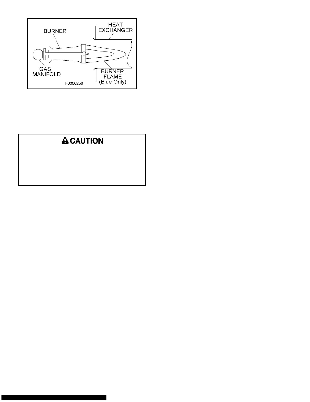
Figure 3
Do not attempt to adjust flame! Your service
representative will perform this adjustment correctly.
Condensate Collection and Disposal System
If the furnace has a condensate drain, it is
incorporated within the furnace and is selfpriming.
The condensate system must not be exposed to
temperatures under 32°F. Use of heat tape is
permissible provided the rate temperature of tape
does not exceed 155°F.
Make sure the condensate drain line does not become
blocked or plugged. Visual inspection of condensate flow
can easily be made while the furnace is operating. Use
a flashlight to illuminate discharge end of the condensate
drain that is placed in the sewer opening. The furnace
will not operate properly if condensate drain line becomes
blocked or plugged. If this event occurs, have the
furnace inspected by a qualified service technician.
Warranty Procedure
When warranty parts are required:
1. Be prepared to furnish the following information:
a. Purchaser's name
b. Complete model number, serial number, and
date of installation.
c. An accurate description of the problem or
defective parts.
2. Contact your dealer or distributor.
Keep this User's Information Manual (including
Warranty) and proof of purchase for your records.
Your warranty is determined from your date of
installation. If proof of your date of installation is not
supplied, the warranty will be based on the
manufacture date code.
Failure to follow the correct warranty procedure could
result in disallowance of warranty claim.
PARTS REPLACEMENT INFORMATION GUIDE
CASING GROUP GAS CONTROL GROUP BLOWER GROUP
Top Panel Manifold Blower Housing
Front Door Burner Blower Motor
Blower Door Shield Top & Bottom Blower Wheel
Burner Access Door Orifice Capacitor
Control Access Door Ignitor Blower Support Leg
Gas Valve
Sensor
ELECTRICAL GROUP HEAT EXCHANGER GROUP INDUCER GROUP
Limit Switch Primary Heat Exchanger Pressure Switch (Low Fire)
Control Board Condensing Heat Exchanger Pressure Switch (High Fire)
Transformer Burner Box Panel Inducer Blower & Motor
Rollout Switch Burner Inlet Plate Inducer Blower Switch
Door Interlock Switch Flue Box Pressure Switch Tubering
Auxiliary Limit Switch (when used)
CONDENSATE DISPOSAL GROUP
Condensate Trap
Condensate Hoses
TO OBTAIN INFORMATION ON PARTS: Consult your installing dealer or classified section of your local telephone
directory under the "Heating Equipment" or "Air Conditioning Contractors & Systems" headings for dealer listing or see the
first page of the installation instruction section of this manual for the name and address to contact.
Have available the Model No. and Serial No. located on the unit rating plate to insure correct replacement part.
WARNING: Improper installation, adjustment, alteration, service or maintenance can cause personal injury or property
damage. Consult a qualified installer, service agency, or your local gas supplier for information or assistance.
20558901 Issue 0442 Page 6 of 6
Page 9
TABLE OF CONTENTS
AFFIX LABEL HERE
INSTALLATION INSTRUCTIONS
UPFLOW OR LEFT HORIZONTAL
TWO STAGE HEAT VARIABLE SPEED
GAS-FIRED CONDENSING
WARM AIR FURNACE
Issue 0442
Safety . . . . . . . . . . . . . . . . . . . . . . . . . . . . . . . . . . . . . . . . . . . 2
Furnace Specifications . . . . . . . . . . . . . . . . . . . . . . . . . . . . . . . 3
Introduction . . . . . . . . . . . . . . . . . . . . . . . . . . . . . . . . . . . . . . . 6
Location/Placement . . . . . . . . . . . . . . . . . . . . . . . . . . . . . . . . . . 6
Air for Combustion & Ventilation . . . . . . . . . . . . . . . . . . . . . . . . 8
Ducting . . . . . . . . . . . . . . . . . . . . . . . . . . . . . . . . . . . . . . . . . . 11
Venting . . . . . . . . . . . . . . . . . . . . . . . . . . . . . . . . . . . . . . . . . . 12
Electrical Connections . . . . . . . . . . . . . . . . . . . . . . . . . . . . . . . . 19
RETAIN THESE INSTRUCTIONS FOR FUTURE REFERENCE
Gas Connections . . . . . . . . . . . . . . . . . . . . . . . . . . . . . . . . . . . 19
Control Board & Variable Speed Motor Features . . . . . . . . . . . . . 21
Unit Sequence of Operation . . . . . . . . . . . . . . . . . . . . . . . . . . . . 22
Start-Up Operation & Checkout . . . . . . . . . . . . . . . . . . . . . . . . . 23
Sequence of Operation . . . . . . . . . . . . . . . . . . . . . . . . . . . . . . . 28
Servicing The Furnace . . . . . . . . . . . . . . . . . . . . . . . . . . . . . . . 29
Control System Diagnostics . . . . . . . . . . . . . . . . . . . . . . . . . . . . 31
Wiring Diagram . . . . . . . . . . . . . . . . . . . . . . . . . . . . . . . . . . . . . 32
Do not store or use gasoline or other
flammable vapors and liquids in the
vicinity of this or any other appliance.
WHAT TO DO IF YOU SMELL GAS:
Installation and service must be performed
by a qualified installer, service agency or
the gas supplier. Installation by an
unqualified person may lead to equipment
damage and/or a hazardous condition
which may cause bodily injury and harm
and, as such, at the sole discretion of the
manufacturer, the entire warranty may be
voided and be of no further force and
effect.
20558801 Issue 0442 Page 1 of 32
• Do not try to light any appliance.
• Extinguish any open flame.
• Do not touch any electrical switch; do
not use any phone in your building.
• Immediately call your gas supplier from
a neighbor's phone. Follow the gas
supplier's instructions.
• If you cannot reach your gas supplier,
call the fire department.
Page 10

SAFETY
The following is a list of safety precautions and their locations in this manual.
These safety rules and precautions must be followed when installing this furnace.
1. Use only with type of gas approved for this furnace. Refer to the furnace rating
plate.
2. Install this furnace only in a location and position as specified in The
Location/Placement Section on page 6 of these instructions.
3. Provide adequate combustion and ventilation air to the furnace space as
specified in Air for Combustion and Ventilation section on page 8 of these
instructions.
4. Combustion products must be discharged outdoors. This furnace requires a
special vent system with adequate clearances around the vent-air intake terminal
(s), as specified in Venting on page 12 of these instructions.
5. As a TYPE FSP CATEGORY IV furnace the combustion air connections, the flue
gas connection, the vent-air intake terminal and condensate trap and drain
system must be as specified in the Venting section starting on page 12 of these
instructions. Venting and drain materials must be as specified and are to be
supplied by the installer. On direct vent systems the vent outlet shall be installed
so as to be in the same atmospheric pressure zone as the combustion air intake.
6. Never test for gas leaks with an open flame. Use a commercially available soap
solution made specifically for the detection of leaks to check all connections, as
specified in The Gas Connection section on page 19 of these instructions.
7. Always install furnace to operate within the furnace's intended temperature-rise
range with a duct system which has an external static pressure within the
allowable range, as specified in Furnace Specifications on page 3 of these
instructions. See furnace rating plate.
8. When a furnace is installed so that supply ducts carry air circulated by the
furnace to areas outside the space containing the furnace, the return air shall
also be handled by duct(s) sealed to the furnace casing and terminating outside
the space containing the furnace. See page 11 for Ducting.
9. A gas-fired furnace for installation in a residential garage must be installed as
specified in The Location / Placement section on page 6 of these instructions.
10. The furnace is not to be used for temporary heating of buildings or structures
under construction. As noted on page 6 under Introduction.
20558801 Issue 0442 Page 2 of 32
Page 11
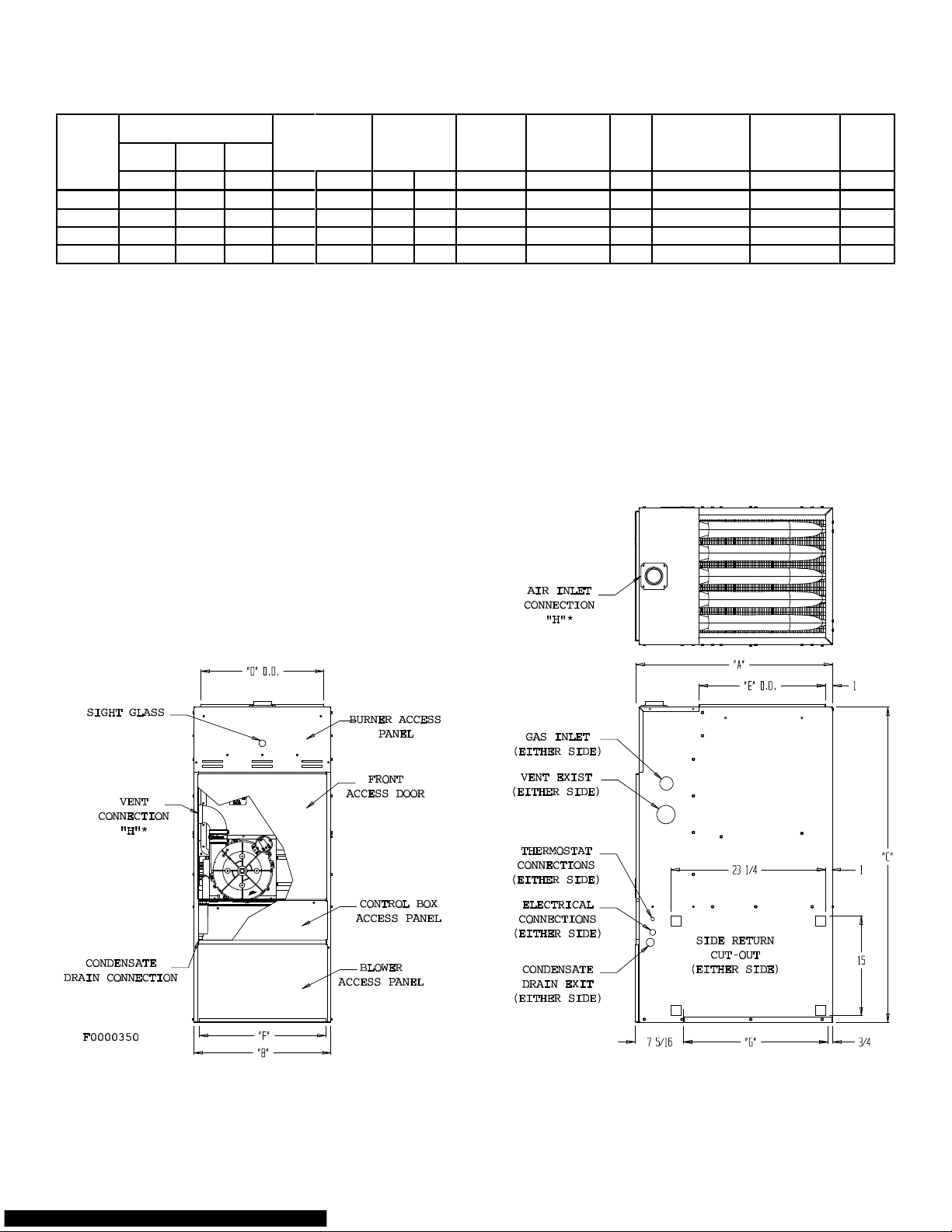
FURNACE SPECIFICATIONS
UNIT DIMENSIONS
MODEL
EV050U3 29 1/2 13 1/2 47 3/8 11 1/2 18 15/16 12 21 5/8 2 15 9.9 14 45-55 131
EV075U3 29 1/2 13 1/2 47 3/8 11 1/2 18 15/16 12 21 5/8 2 15 9.9 14 50-60 140
EV100U4 29 1/2 17 47 3/8 15 18 15/16 15 1/2 21 5/8 2 15 11.8 14 50-60 167
EV125U5 29 1/2 20 1/2 47 3/8 18 1/2 18 15/16 19 21 5/8 2 20 15 12 50-60 193
LENGTH WIDTH HEIGHT
A B C D E F G H
DUCT SUPPLY
OPENING
DUCT
RETURN
OPENING
AIR INLET
& VENT
CONNECTION
DIA.*
MAX. OVER
CURRENT
PROTECTION
MAX.
UNIT
AMPS
ELECTRICAL
SUPPLY MIN.
WIRE SIZE(AWG)
TEMPERATURE
RISE
RANGE
WEIGHT
* SEE TABLES 3 AND 4 ON PAGES 15 AND 16 FOR ALLOWABLE MAX VENT AND AIR INLET LENGTHS AND DIAMETERS.
NET
LBS
20558801 Issue 0442 Page 3 of 32
Page 12
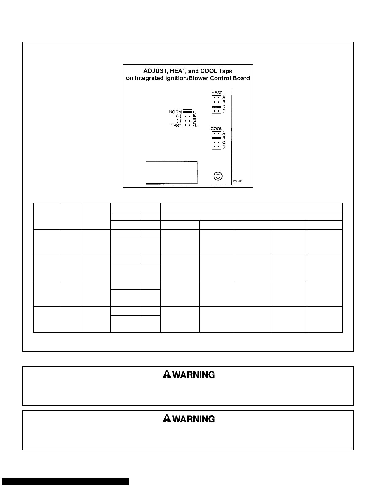
BLOWER MOTOR SPECIFICATIONS AND AIRFLOW ADJUSTING DATA
Adjusting Airflow
MODEL
EV050U3 1/2 10 X 6
EV075U3 1/2 10 X 6
EV100U4 3/4 12 X 9
EV125U5 1 12 X 12
MOTORHPBLOWER
WHEEL
HEAT SETTING COOL SETTINGS
ADJUST HEAT COOL CFM @ .50 STATIC
HEATING CFM ADJUSTMENT SETTING "A" SETTING "B" SETTING "C" SETTING "D"
NORM A NORM 1200 1000 800 600
LOW FIRE 600
HIGH FIRE 775 ( - ) 1020 850 680 510
NORM A NORM 1200 1000 800 600
LOW FIRE 1000
HIGH FIRE 1230 ( - ) 1020 850 680 510
NORM A NORM 1600 1400 1200 1000
LOW FIRE 1240
HIGH FIRE 1550 ( - ) 1360 1190 1020 850
NORM A NORM 2000 1800 1600 1400
LOW FIRE 1250
HIGH FIRE 1940 ( - ) 1700 1530 1360 1190
( + ) 1380 1150 920 690
( + ) 1380 1150 920 690
( + ) 1800 1610 1380 1150
( + ) 2200 2070 1840 1610
When operating the furnace in the heating mode, the static pressure and the temperature rise (supply air temperature
minus return air temperature) must be within those limits specified on the rating label. Failure to follow this warning
could lead to severe furnace damage.
Turn OFF all gas and electrical power to furnace before performing any maintenance or service on unit. (Unless
specific test requires gas and electrical supplies.) Failure to take this precaution may result in personal injury due
to electrical shock or uncontrolled gas leakage.
20558801 Issue 0442 Page 4 of 32
Page 13

FURNACE WIRING SPECIFICATIONS
20558801 Issue 0442 Page 5 of 32
Page 14

The furnace cabinet must have an uninterrupted or unbroken electrical ground to minimize personal injury if an
electrical fault should occur. The unit must also be electrically grounded in accordance with local codes, or in the
absence of local codes, with the latest edition of the (U.S.) National Electrical Code ANSI/NFPA No. 70 or CSA
Standard C22.1; Part 1 Canadian Electrical Code, if an external electrical source is utilized. DO NOT use gas piping
as an electrical ground.
INTRODUCTION
This furnace is design certified by CSA International as a category IV furnace and is dual certified as direct vent furnace
(two pipe system) using outside air for combustion or as a non-direct vent furnace (one pipe system) using air from inside
the structure for combustion.
It is shipped as a packaged unit, complete with burners and controls, and requires a line voltage (120V) connection to
the junction box, a thermostat hook-up as per the wiring diagram, a gas line connection, a condensate drain connection,
ducting and flue piping. This furnace can be installed in either upflow or horizontal (left) airflow positions at no time
should this unit be operated on its back. The design of this furnace is NOT CSA Certified for installation in
recreation vehicles, in manufactured (mobil) homes, outdoors or for temporary construction heating.
This furnace has been designed to interface with split system cooling equipment (approved by a nationally recognized
testing laboratory) so as to provide "year round air conditioning". The blower has been sized for both heating and cooling
and is equipped with a variable speed circulation air blower motor to deliver a constant air flow.
The furnace installation must conform with local building codes or in the absence of local codes, with the latest edition
of the (U.S.) National Fuel Gas Code ANSI Z223.1 (NFPA-54) or Canadian Natural Gas and Propane Installation Codes
CSA B149.1.
For complete information on installation standards consult the (U.S.) National Fuel Gas Code, obtainable from the
National Fire Protection Association, Inc., Batterymarch Park, Quincy, MA 02269 or the American Gas Association, 1515
Wilson Boulevard Arlington, VA 22209 or the Canadian installation codes obtainable from Canadian Standards Association,
178 Rexdale Boulevard, Etobicoke, Ontario, Canada M9W 1R3.
This furnace is designed for minimum continuous return-air temperature of 60°F dB or intermittent operation down to
55°F dB such as when used with a night setback thermostat. Return-air must not exceed a maximum continuous
temperature of 85°F dB.
These instructions are written for individual residential installation only. For multi-unit installation or
commercial applications, please contact manufacturer for recommendations.
LOCATION / PLACEMENT
Site Selection: This furnace may be located in an attic, closet, basement, crawl space, alcove or suspended from the
ceiling of a utility room or basement. Select a location that will meet all requirements for safety,
clearances, ventilation and combustion air, ductwork design, gas piping, electrical wiring and venting.
Clearances: The following minimum clearances, or greater, must be provided between the furnace and adjacent
construction.
TABLE 1 MINIMUM INSTALLATION CLEARANCES
"UPFLOW" POSITION "HORIZONTAL (LEFT)" POSITION
Suitable for alcove or closet installation† on combustible
flooring at minimum clearance from adjacent construction
not less than the following:
Top Sides Back Front Vent
2" 1" 1" 3" 0"
† For closet installation see Air for Combustion and Ventilation.
20558801 Issue 0442 Page 6 of 32
Suitable for attic, alcove or closet installation† on
combustible flooring at minimum clearance from adjacent
construction not less than the following:
* Line contact only permissible between lines formed by
intersection of the top and two sides of the furnace jacket
and building joist, studs, or framing.
Page 15

Failure to comply with all of the clearances will
create a fire hazard.
INSTALLATION POSITIONS
If furnace is tilted back condensate will collect in the
secondary heat exchanger which will result in
improper combustion, fire hazard, or other unsafe
conditions which could result in property damage,
personal injury or death.
If the furnace is to be installed in a crawl space,
consult local codes. (Use of a concrete pad 1" to 2" thick
is recommended.)
If the furnace is to be suspended from the ceiling, it
will be necessary to use steel pipe straps around each
end of the furnace. These straps should be attached to
the furnace with sheet metal screws and to the rafters
with bolts. The furnace may also be suspended by using
an angle iron frame bolted to the rafters. (See Table on
page 3 for size and weight of furnace.) Care must be
taken to allow for service access.
If a furnace is to be installed in a residential garage,
it must be installed so the burners and the ignition source
are located not less than 18" above the floor and the
furnace must be located or protected to avoid physical
damage by vehicles.
The furnace should not be connected to an
operational chimney. The furnace should also be located
as near to the center of the air distribution system as
possible, and should be installed level.
This furnace may be installed on non-combustible or
on wood flooring, however, it must not be installed
directly on carpeting, tile or any other combustible
material.
In a horizontal position, line contact with combustibles
is only permissible between lines formed by the
intersection of the furnace top, the front and back sides,
and building joists, studs or framing (See Figure 1).
Figure 1
HORIZONTAL LINE CONTACT
Furnace must not lean back. It must be level or
tilt up to 2° to the front. (See Figure 1.)
A clearance of at least 30" should be provided at the
front of the unit for servicing. For attic installations, the
passageway and servicing area adjacent to the furnace
should be floored.
If this furnace is installed in a garage and/or any
unconditioned space, where local plumbing code
would require potable water supply piping to be
protected; a thermostatically controlled heat tape
must be installed along the entire length of the
condensate drain in the unconditioned space. Any
blockage of the condensate drain will result in
improper combustion, fire hazard, or other unsafe
conditions which could result in property damage,
personal injury or death.
Do not place combustible material on the furnace
jacket. Failure to comply with this warning will
create a fire hazard.
This furnace is not watertight and is not designed
for outdoor installation. This furnace shall be
installed in such a manner as to protect the
electrical components from water. Outdoor
installation would lead to a hazardous electrical
condition and to premature furnace failure.
20558801 Issue 0442 Page 7 of 32
Page 16

AIR FOR COMBUSTION AND VENTILATION
Contaminated Combustion Air:
If the furnace is to be installed in a structure defined
as having contaminated combustion air, the furnace must
use the direct vent (two pipe) configuration using noncontaminated outside air for combustion. Allowing
exposure to substances containing chlorine or fluoride
could harm the furnace and void the warranty.
Substances to avoid include, but are not limited to:
• Permanent wave solutions
• Chlorinated waxes and cleaners
• Chlorine based swimming pool chemicals
• Water softening chemicals
• De-icing salts or chemicals
• Carbon tetrachloride
• Halogen type refrigerants
• Cleaning solvents (such as perchloroethylene)
• Printing inks, paint removers, varnishes, etc.
• Hydrochloric acid
• Cements and glues
• Antistatic fabric softeners for clothes dryers
• Masonry acid washing materials
• Unrefined gases
Contaminated combustion air may cause premature
failure of the heat exchanger that may lead to a
hazardous condition and/or bodily harm, or loss of
life.
allows for the combustion air to be supplied directly
to the furnace from the outdoors. Ventilation needs
only to be considered when furnace is installed as
direct vent (two pipe). Non-direct venting (one pipe)
requires both combustion and ventilation air
requirements from the furnace location.
For purposes of this instruction the following
definitions apply:
Confined Space: A space whose volume is less
than 50 cubic feet per 1000
Btu/hr of the aggregate input
rating of all appliances installed
in that space.
Unconfined Space: A space whose volume is not
less than 50 cubic feet per 1000
Btu/hr of the aggregate input
rating of all appliances installed
in that space. Rooms
communicating directly with the
space in which the appliances
are installed, through openings
not furnished with doors, are
considered a part of the
unconfined space.
If the installation area meets the definition of
"Unconfined Space" and does not have additional air
requirements as described, the furnace may be installed
without making special provisions for combustion and
ventilation air.
Adequate Ventilation and Combustion Air:
This section is provided to give guidelines for the
introduction of air for ventilation and combustion air. The
total quantity of air provided to the installation area must
equal the requirements of all gas appliances in the area.
Adequate facilities for providing air for combustion
and ventilation must be provided in accordance with the
latest edition of the National Fuel Gas Code ANSI
Z223.1/NFPA54 or CSA B149.1 Natural Gas and Propane
Installation Codes, or applicable provisions of the local
building codes.
The furnace shall be installed in a location in which
the facilities for ventilation permits satisfactory combustion
of gas, proper venting and maintenance of ambient
temperature at safe limits under normal conditions of use.
The furnace shall be located so as not to interfere with
proper circulation of air.
In addition to air needed for combustion, ventilation in
the form of process air must be provided as required for:
cooling of equipment or material, controlling dew point,
heating, drying, oxidation or dilution, safety exhaust and
odor control. Air must be supplied for ventilation,
including all air required for comfort and proper working
conditions for personnel. Direct venting (two pipe)
Whenever this furnace is installed in an area along
with one or more gas appliances, the total Btu/hr
input of all appliances (using maximum input of
each appliance) must be included when determining
the free area requirements for combustion and
ventilation air openings.
Do not block the combustion or ventilation air
openings in the furnace. Any blockage will result in
improper combustion and may result in a fire
hazard or unsafe condition.
20558801 Issue 0442 Page 8 of 32
Page 17

If ventilation and/or combustion air must be supplied to the "Confined Space" from inside the building structure, two
permanent openings to an additional room of sufficient volume as to combine the volumes of the spaces to meet the
criteria for an "Unconfined Space" must be created. Each opening must have a free area of not less than one square
inch per 1000 Btu per hour of total input of all appliances within the "Confined Space" (but not less than 100 square
inches). These openings must be located 12 inches from the top and bottom of the furnace area respectively and must
be at least 3 inches long on the smaller side of the opening (See Figure 2). Neither opening can be blocked at any time.
Figure 2 CONFINED SPACE / INDOOR AIR
TOTAL INPUT
(Btuh)
40,000
60,000
80,000
100,000
120,000
140,000
160,000
EXAMPLE:
50,000 Btuh Furnace & 10,000 Btuh Water
Heater = 60,000 Btuh Total Input = 12"
Dia. Round Duct.
MIN. FREE AREA
(Sq. In.)
100
100
100
100
120
140
160
ROUND DUCT
(Dia. In.)
12
12
12
12
13
14
15
If ventilation and/or combustion air must be supplied to the "Confined Space" from outside the building structure,
two permanent openings to the outdoors must be created. Each opening must have a free area of not less than one
square inch per 4000 Btu per hour of total input of all appliances within the "Confined Space". These openings must
be located 12 inches from the top and bottom of the furnace area respectively (See Figures 3, 4, and 5). Neither
opening can be blocked at any time.
Figure 3 CONFINED SPACE / OUTDOOR AIR
TOTAL INPUT
(Btuh)
40,000
60,000
80,000
100,000
120,000
140,000
160,000
EXAMPLE:
50,000 Btuh Furnace & 10,000 Btuh Water
Heater = 60,000 Btuh Total Input = 5" Dia.
Round Duct.
20558801 Issue 0442 Page 9 of 32
MIN. FREE AREA
(Sq. In.)
10
15
20
25
30
35
40
ROUND DUCT
(Dia. In.)
4
5
5
6
6
7
8
Page 18

Figure 4
Figure 5
CONFINED SPACE / OUTDOOR AIR
FROM ATTIC
CONFINED SPACE / OUTDOOR AIR
FROM ATTIC & CRAWL SPACE
When horizontal ducts are used to supply air from the
outdoors, they must be of the same cross sectional area
as the free area of the openings to which they connect.
The minimum dimension of rectangular air ducts must not
be less than 3 inches. Each opening must have a free
area of not less than one square inch per 2,000 Btu per
hour of total input of all appliances within the "Confined
Space". These openings must be located 12 in. from the
top and bottom of the furnace area. Neither opening can
be blocked at any time (See Figure 6).
Figure 6
CONFINED SPACE / OUTDOOR
AIR THROUGH HORIZONTAL DUCTS
Furnaces installed with combustion air drawn from
a heated space which includes exhaust fans,
fireplaces, or other devices that may produce a
negative pressure should be considered confined
space installations.
For an attic installation it is important to keep
insulation 12" or more away from any furnace
openings. Some types of insulating materials may
be combustible.
20558801 Issue 0442 Page 10 of 32
Page 19

DUCTING
The proper sizing of warm air ducts is necessary to insure satisfactory heating operation. Ductwork should be in
accordance with the latest editions of (U.S.) NFPA-90A (Air Conditioning Systems) and NFPA-90B (Warm Air Heating
and Air Conditioning Systems) or Canadian equivalent.
Ductwork Recommendation:
The supply duct work should be attached to the
flanged opening provided at the discharge end of the
furnace. See page 3 "Furnace Specifications" for the
dimensions of this opening.
A left, right, or bottom return air opening must be
used as determined by the layout of the installation. An
externally mounted air filter is required.
This furnace has a two piece bottom panel. For
bottom or end duct return, remove the back portion of the
bottom panel by removing the four (4) screws - two (2) on
each side toward the back of the furnace (See Figure 7).
Tilt furnace toward the front, the back portion of the panel
will drop down. Then the back portion can be removed
by pulling toward the back of the furnace.
Figure 7
BOTTOM PANEL REMOVAL
viewed for possible openings using light assistance or
a probe can be inserted by sampling the air stream.
The access panel shall be designed so as to prevent
leaks when locked in position. If an air conditioning
coil is installed, the access panel to the coil can be
used for this purpose.
When supply ducts carry air circulated by the
furnace to areas outside the spaces containing the
furnace, the return air shall also be handled by a
duct sealed to the furnace casing and terminating
outside the space containing the furnace. Incorrect
ductwork termination and sealing will create a
hazardous condition that could lead to bodily harm.
Air openings, intake and outlet pipes, return air
grilles and warm air registers must not be
obstructed.
Knockouts are provided on both sides of the furnace
to facilitate the cutout required to the return air ductwork.
Furnace cutouts must be the full size specified by the
corner markers. Undersized cutouts will adversely
affect the airflow capability of the furnace and could
cause overheating of the heat exchanger.
The following recommendations should be followed
when installing the ductwork:
1. Install locking-type dampers in all branches of the
individual ducts to balance out the system. Dampers
should be adjusted to impose the proper static at the
outlet of the furnace.
2. Noncombustible flexible duct connectors are
recommended to connect both the supply and return
ducts to the furnace.
3. In cases where the return air grille is located close to
the blower inlet, there should be at least one 90° air
turn between blower and return grille. Further
reduction in sound can be accomplished by installing
acoustical air turning vanes and/or lining the inside of
the duct with acoustical material.
4. It is recommended that the supply duct be provided
with a removable access panel. This opening shall
be accessible when the furnace is installed and shall
be of such a size that the heat exchanger can be
Filters:
Air filters must be used in every installation. For side
return installations, air filters must be installed external to
the furnace casing. An external filter rack kit with filter
(parts No. 20069901 or Cat. No. 68L75 for 12 / 15½" x
25" sizes and 20069902 or Cat. No. 68L76 for 15½ / 19"
x 25" sizes) is available as an optional accessory.
For bottom (end) return installations, the above
optional external rack may be used, if the unit was not
provided with a internal filter. Minimum filter size and
suggested filter materials are shown in Table 2. (If
different type filter is used, it must be an equivalent high
airflow capacity.)
Table 2 EXTERNAL FILTER RACK SIZE
MODEL
050-3
075-3
100-4 15 ½ X 25 15 ½ X 25
125-5 15 ½ X 25 19 X 25
SIDE
RETURN
15 ½ X 25 12 X 25
BOTTOM/END
RETURN
20558801 Issue 0442 Page 11 of 32
Page 20

When installing the furnace with cooling equipment for
year round operation, the following recommendations
must be followed for series or parallel air flow:
1. In series flow applications, the coil is mounted after
the furnace in an enclosure in the supply air stream.
The furnace blower is used for both heating and
cooling airflow.
2. In parallel flow installation, dampers must be provided
to direct air over the furnace heat exchanger when
heat is desired and over the cooling when cooling is
desired. At no time may the evaporator coil be
located on the return air side of the heat exchanger.
IMPORTANT: The dampers should be adequate to
prevent cooled air from entering the
furnace, and if manually operated, must
be equipped with means to prevent
operation of either the cooling unit or
furnace unless the damper is in the full
cool or full heat position.
VENTING
The coil MUST be installed on the air discharge
side of the furnace. Under no circumstances
should the air flow be such that cooled, conditioned
air can pass over the furnace heat exchanger. This
will cause condensation in the heat exchanger and
possible failure of the heat exchanger that could
lead to a fire hazard and/or hazardous conditions
that may lead to bodily harm. Heat exchanger
failure due to improper installation will not be
covered by warranty.
Venting for this category IV furnace must be with
schedule 40 PVC, CPVC or ABS pipe including all elbows
and vent terminals. All pipe and fittings must conform to
the American Society for Testing and Material (ASTM),
and American National Standards Institute (ANSI)
Standards. PVC primer and solvent cement used to
secure all PVC joints must conform to ASTM D2564.
Common venting with other condensing appliances
or non-condensing appliances is not allowed.
In all direct vent (two pipe) instances, the vent
outlet shall be installed so as to be in the same
atmospheric pressure zone as the combustion air
intake.
All combustion air and exhaust piping must be
installed in accordance with local codes and these
instructions. For additional venting information refer to
ANSI/NFPA 211 Chimney, Fireplaces, Vents and Solid
Fuel Burning Appliances or Canadian equivalent.
1. Determine termination location based on clearances
provided in Figure 8 and the appropriate termination
spacing shown in Figures 10, 11, 12, 14, and 15.
2. Ensure all vent and air termination remain at least 12"
above ground or normally expected snow
accumulation height.
3. The vent for this appliance shall not terminate
a) Over public walkways; or
b) Near soffit vents or crawl space vents or other
areas where condensate or vapor could creat a
nuisance or hazard or cause poperty damage; or
c) Where condenstae vapor could cause damage or
could be detrimental to the operation of
regulators, relief valves, or other equipment.
4. Do not terminate within 4' horizontally from any
electric meter, gas meter, regulator or any relief
equipment. These distances apply to U.S.
installations. In Canada, the Canadian Fuel Gas
Code takes precedence over this requirement.
5. Vent pipe systems (2 pipe or 1 pipe) termination
clearances will follow the direct vent termination
clearances as shown in Figure 8.
Failure to terminate vent runs above the annual
snow accumulation level may result in nuisance
furnace shutdown and/or hazardous condition that
may lead to bodily harm or loss of life.
20558801 Issue 0442 Page 12 of 32
Page 21

Figure 8
20558801 Issue 0442 Page 13 of 32
VENT TERMINATION CLEARANCES
Page 22

Horizontal (Side Wall) Vent Termination:
To prevent blockage of the combustion air and
exhaust vent by snow, vent termination must be made 12"
(in.) above the anticipated maximum snow accumulation
level (See Figure 10).
A minimum of 4' (ft.) clearance must be provided from
electric meters, gas meters, regulators and relief
equipment. In Canada refer to the current Canadian Fuel
Gas Code.
Terminations must terminate not less than onefoot above, below or horizontal from any inlet to
building.
Do not terminate over public walkways or over an
area where condensate or vapor could create a nuisance
or hazard. Inlet and outlet pipes may not be vented
directly above each other.
Figure 10
HORIZONTAL VENT TERMINATION
The optional concentric vent termination kit (2"
diameter Part No. 20280901 / Cat. No. 87L83 or 3"
diameter Part No. 20280902 / Cat. No. 87L84) may also
be used for horizontal (side wall) vent termination. 2"
diameter concentric vent approved for use with 50
and 75 models only. Special consideration for this
termination system should be given to: 1) possible
damage from the vapors to plants/shrubs, other
equipment and building materials, 2) possible damage to
the terminal from foreign objects, 3) wind effects that may
cause recirculation of flue products, debris or light snow,
and 4) visible vent vapor.
The concentric vent kit has complete installation
instructions.
Figure 12
CONCENTRIC VENT HORIZONTAL TERMINATION
Figure 11
ALTERNATE HORIZONTAL VENT TERMINATION
NOTE: If exhaust vent pipe is extended more than 24",
insulate the vent pipe between the two outside
90° elbows with closed cell insulation.
Figure 13
CONCENTRIC VENT HORIZONTAL MOUNTING
Vertical Vent Termination:
The vertical vent terminations should be sealed with
a plumbing roof boot or equivalent flashing.
The inlet of the intake pipe and the end of the
exhaust vent must terminate no less than 12" (in.) above
the roof or snow accumulation level, and 12" (in.) away
from a vertical wall or other protrusion (See Figure 14).
In all venting configurations it is required to use
terminations specified. The intake elbow is field supplied.
20558801 Issue 0442 Page 14 of 32
Page 23

The vertical vent system can be installed through an
existing chimney provided that:
a. No other appliance is vented into the
chimney.
b. The vent system does not terminate
within the chimney and the termination
clearances shown in Figure 14 are
maintained.
c. Both the air intake and exhaust vent run
the length of the chimney.
d. The top of the chimney is sealed and
weather proofed.
Figure 14
VERTICAL VENT TERMINATION
Figure 16
CONCENTRIC VENT VERTICAL MOUNTING
Allowable Vent Lengths:
The minimum allowable vent system for either 2"
diameter or 3" diameter venting is 5 ft. and one (1) elbow.
Concentric vent kit terminated systems must use
Direct Vent (2 pipe) System allowable max vent lengths
for the appropriate diameter pipe.
Refer to Tables 3 and 4 for the proper pipe diameters
and maximum allowable vent lengths.
The optional concentric vent termination kit (2"
diameter Part No. 20280901/Cat. No. 87L83 or 3"
diameter Part No. 2028902/Cat. No. 87L84) may also be
used for vertical vent termination. Special consideration
for this termination system should be given to: 1)
possible damage from vapors to roof over hangs, other
equipment and building materials, 2) possible damage to
the termination from foreign objects, 3) wind effects that
cause recirculation of flue products, debris or light snow
and 4) visible vent vapor effects on surrounding windows
and other openings. The concentric vent kit has complete
installation instructions.
Figure 15
CONCENTRIC VENT VERTICAL TERMINATION
TABLE 3
Allowable Max Vent Lengths for 2" Diameter Venting
APPLICATION
Elbows Allowed 1 2 3 4 5
Models 50 / 75 with Direct Exhaust
(1 Pipe) System
Models 50 / 75 with Direct Vent
(2 Pipe) System
Models 100 with Direct Exhaust
(1 Pipe) System - Upflow Only
Models 100 with Direct Vent
(2) Pipe) System - Upflow Only
Models 100 with Direct Exhaust
(1 Pipe) System - Horizontal Only
Models 100 with Direct Vent
(2 Pipe) System - Horizontal only
Models 125 with Direct Exhaust
(1 Pipe) System
Models 125 with Direct Vent
(2 Pipe) System
* Notes:
1. Vent system begins at outside of furnace casing.
2. Two 45° elbows are equivalent to one 90° elbow.
3. Do not include termination tee and elbow in calculation of vent length.
4. This table is applicable for elevations up to 2,000 ft. For higher elevations
decrease vent pipe lengths by 8% per 1,000 ft. of altitude.
5. Concentric Vent Kit terminated systems must use Direct Vent Lengths.
6. 2" concentric Vent Kit approved for use with 50/75 models only.
* Allowable Max Vent Lengths of 2" dia.
PVC, ABS or CPVC SCH 40 Pipe
60 58 55 53 50
60 58 55 53 50
35 30 24 18 12
35 30 24 18 12
20 15 9 4 --
20 15 9 4 --
20 15 9 4 --
20 15 9 4 --
20558801 Issue 0442 Page 15 of 32
Page 24

TABLE 4
Allowable Max Vent Lengths for 3" Diameter Venting
APPLICATION
Elbows Allowed 1 2 3 4 5
Models 50 / 75 with Direct Exhaust
(1 Pipe) System
Models 50 / 75 with Direct Vent
(2 Pipe) System
Models 100 with Direct Exhaust
(1 Pipe) System
Models 100 with Direct Vent
(2 Pipe) System
Models 125 with Direct Exhaust
(1 Pipe) System
Models 125 with Direct Vent
(2 Pipe) System
* Allowable Max Vent Lengths of 3" dia.
PVC, ABS or CPVC SCH 40 Pipe
80 76 73 70 65
80 76 73 70 65
65 61 58 55 50
65 61 58 55 50
65 61 58 55 50
65 61 58 55 50
Notes:
1. Vent System begins at outside of furnace casing.
2. Two 45° elbows are equivalent to a 90° elbow.
3. Do not include termination tee and elbow in calculation of vent length.
4. This table is applicable for elevations up to 2,000 ft. For higher
elevations decrease vent pipe lengths by 8% per 1,000 ft. of altitude.
5. Concentric Vent Kit terminated systems must use Direct Vent lengths.
6. All models are factory shipped equipped for 2" diameter venting.
Conversion to 3" diameter venting require field supplied fittings.
4. All pipe should be supported using clamps and/or
straps. These supports should be at least every four
(4) feet, or as required by local codes.
5. All horizontal vent runs must be sloping upwards to
obtain 1/4" (in.) rise per foot of pipe from the furnace
to the vent terminal. This insures proper drainage of
the condensate back to the condensate drain.
Failure to maintain this rise will cause condensate to
accumulate in the pipe.
6. Direct Vent (two pipe) units may have either a 90°
elbow or a straight coupling attached to the air inlet
plate. Do not seal the top joint of the fitting. This
joint must be left unglued to facilitate unit access
during any required maintenance.
7. Joints in PVC should be sealed with PVC cement and
checked for leaks. ABS or CPVC venting should use
sealant as specified by the pipe manufacturer.
8. Check all local codes for any variance.
Figure 17
UPFLOW VENT OPTIONS
Flue Pipe Installation:
NOTE: Make sure of alignment and fit, before gluing
pieces in place!!
The flue may exit the cabinet either through the right
or the left side panel, depending on the requirements of
the installation. If the unit is installed in a horizontal-left
discharge position, it is required to exit through the right
side panel, so the flue is pointing straight up when the
unit is installed. See Figures 17 and 18 for
configurations.
1. Install factory supplied 2" diameter street sweep (long
radius) elbow onto inducer outlet (See Figure 17 and
18). Face elbow at appropriate casing side and
secure using attached pipe clamp.
2. Using 2" diameter SCH 40 PVC (ABS or CPVC) pipe,
install a short piece of pipe into the elbow. The pipe
should be long enough to leave approximately one
inch (1") protruding out of the casing side minimum
for connection to another fitting. Transitions must be
mounted to allow condensate to flow to inducer outlet
coupling (See Figures 17 and 18).
3. 2" diameter connections are made directly to the
supplied 2" diameter street sweep elbow. 3" diameter
connections require 2" to 3" transition. Transition to
be located wihtin 12 linear inches of cabinet. The
2" to 3" transitions must be mounted to allow
condensate to flow to inducer outlet coupling (See
Figures 17 and 18).
Figure 18
LEFT HORIZONTAL VENTING
20558801 Issue 0442 Page 16 of 32
Page 25

Installation of Air Inlet Connector:
The air inlet connector must be installed on the top
panel of the furnace (See Figure 19). The connector and
mounting screws are shipped in the vestibule of the
furnace. The air inlet connector is placed over the hole
pattern in the top panel and the lip on the bottom of the
connector must fit into the hole on the top panel. The
connector is then secured to the top panel using the four
(4) No. 10 x 5/8 sheet metal screws. The screws should
be tightened securely, so the lip of the connector is
seated properly in the hole in order to prevent air
leakage. When installing furnace as non-direct vent (one
[1] pipe), a field supplied PVC street elbow must be
attached to the air inlet connector with the elbow open
end facing front (Figure 19. When installing furnaces as
direct vent (two [2] pipe), air inlet piping must match vent
pipe in length and configuration. 2" diameter connections
are made directly to the supplied air inlet connector. 3"
diameter connections require 2" to 3" transition.
Transition to be located within 12 linear inches of
cabinet.
Figure 19
AIR INLET CONNECTOR ASSEMBLY
2. Remove horizontal condensate opening knockout
from left side of cabinet as shown in Figure 22
3. Remove inducer to condensate trap hose from unit as
shown in Figure 20. Resize this hose by removing
approximately 4" from straight end as shown in
Figure 23. Attach supplied 1/2" hose coupling to cut
end. Connect supplied 1/2" hose with formed elbow
to 1/2" coupling to condensate trap as shown in
Figure 22. Re-attach hose to drain connection at
inducer outlet (See Figure 23).
4. Remove secondary heat exchanger drain hose from
unit see Figure 21 Resize hose by removing
approximately 2.5" from secondary heat exchanger
end and 1" from the trap end, (See Figure 22).
Attach supplied 1/2" street elbow to re-sized hose
(See Figure 23.
5. Connect secondary heat exchanger drain hose from
secondary heat exchanger drain to condensate trap
(See Figure 23).
6. Connect pressure switch hose to condensate trap
(See Figure 23).
Terminate the combustion air intake in the same
pressure zone as the vent outlet and as far as
possible from the air conditioning unit or heat pump,
swimming pools, swimming pool pumping units and
dryer vents.
To "Convert" from Upflow to Horizontal (Left) Airflow:
This furnace is shipped for installation in the upflow
configuration, but may be installed in a horizontal right-toleft airflow direction. The changes needed to "convert" to
the horizontal position are:
7. Cover original condensate trap opening in blower
partition panel with cover plate and mounting screws
from accessory part bag.
Figure 20
CONDENSATE TRAP HOSE CONNECTIONS
1. Disconnect hoses from condensate trap, remove
fastening screws and remove trap as shown in Figure
21.
20558801 Issue 0442 Page 17 of 32
Page 26

Figure 21
Figure 22
UPFLOW TRAP
HORIZONTAL TRAP
Condensate Disposal Drain:
This furnace must use the condensate trap supplied
with the unit (See Figures 17 and 18) for proper drain
installation. The drain must terminate at a floor drain,
sewer system, or drain vent for proper condensate
removal. Drain installation must conform to local building
codes.
In addition, the trap must be filled with water on the
initial start-up of the unit. Installation location may require
that the trap be filled at the beginning of each heating
season. Filling the trap should be accomplished by: 1)
disconnecting the inducer outlet coupling hose from the
inducer outlet coupling, 2) pouring approximately 12 oz.
of tap water into the inducer outlet coupling hose and 3)
reconnecting the inducer outlet coupling hose to the
inducer outlet coupling.
When terminating the condensate disposal into a
condensate pump, the condensate drain should not be
submerged into the pump.
Do not connect the condensate drain to a positive
pressure such as an A/C coil drain. If connecting to a
common A/C coil drain special pressure relieving means
must be taking. (ie. atmospheric vent install between the
two traps).
In addition, if this unit is placed in an unconditioned
space such as an attic or crawlspace where local
plumbing code would require potable water supply piping
to be protected; a thermostatically controlled heat tape
must be installed along the entire length of
condensate drain in the unconditioned space.
Figure 23
HORIZONTAL LEFT CONDENSATE TUBING
Failure to install a heat tape on condensate drain
lines in unconditioned spaces could lead to
nuisance furnace shut-down, water damage, and/or
a hazardous condition which may lead to bodily
harm, or loss of life.
20558801 Issue 0442 Page 18 of 32
Page 27

ELECTRICAL CONNECTIONS
When installed, the furnace must be electrically
grounded in accordance with local codes or, in the
absence of local codes, with the (U.S.) National Electrical
Codes, ANSI/NFPA 70 or CSA Standard C22.1; Part 1
Canadian Electrical Code. For proper installation refer to
furnace rating label for electrical ratings and for the field
wiring of this unit refer to furnace wiring specifications on
page 5 or alternately from the wiring diagram on page 31.
In all instances, other than wiring for the thermostat, the
wiring to be done and any replacement of wire shall
conform with the temperature limitation for Type T wire
[63°F rise (35°C)].
The electrical connections and the thermostat
connections are made at the openings on either side
panel of the unit in the control box area. Either side may
be used as convenient, but the provided hole plugs must
be inserted in the unused holes.
The control system depends on the correct polarity of
the power supply. Connect "Hot" (H) wire and "Ground"
(G) wire as shown in furnace wiring specification on
wiring diagram. Use reference Table on page 3 (Furnace
Specifications), for over current protection, max unit amp
rating and wire size. Use copper wire only for 120Vsupply service to unit. When replacing any original
internal wiring, use only 105°C, 16 AWG copper wire.
Thermostat:
Instructions for wiring the thermostat are packed in
the thermostat (field supplied) box. Make the thermostat
connections as shown in furnace wiring specifications at
the 24-volt terminal board located in the control box.
Single Stage Thermostat Operation:
The automatic heat staging option allows a single stage
thermostat to be used with a two stage furnace. To
activate this option, move the jumper pin (see Figure 24)
to desired setting (5 minutes or 10 minutes). The furnace
will start on first (1ST) stage heat and stay at first (1ST)
stage heat for the duration of the selected time before
switching to 2nd stage heat.
Figure 24
AUTOMATIC HEAT STAGING JUMPER
When installing optional accessories to this appliance,
follow the manufacturer's installation instructions included
with the accessory.
The unit cabinet must have an uninterrupted or
unbroken electrical ground to minimize personal
injury if an electrical fault should occur. This may
consist of electrical wire or approved conduit when
installed in accordance with existing electrical
codes. Do not use gas piping as an electrical
ground. Failure to follow this warning can result in
an electrical shock, fire, bodily harm, or loss of life.
GAS CONNECTIONS
Gas piping shall be of such size and so installed as
to provide a supply of gas sufficient to meet maximum
demands without undue loss of pressure between the gas
meter and the furnace. It is recommended that the gas
line to the furnace shall be a separate line direct from the
meter, unless the existing gas line is of ample capacity.
Refer to gas pipe capacity table in the National Fuel Gas
Code ANSI Z223.1/NFPA54 or the CSA B149.1 Natural
Gas and Propane Installation Codes.
If local codes allow the use of a flexible gas appliance
connector, always use a new listed connector. Do not
use a connector which has previously serviced another
gas appliance.
Use a joint compound (pipe dope) that is resistant to
the action of liquefied petroleum gases or any other
chemical constituents of the gases to be conducted
through the piping.
20558801 Issue 0442 Page 19 of 32
For proper furnace operation the maximum gas
supply pressure is 14" w.c. and the minimum gas
supply pressure is 4.5" w.c. - natural (11" w.c. - LP)
as shown on rating label.
Before any system of gas piping is finally put into
service, it should be carefully tested to determine if it is
gas tight. Check all piping for leaks. The piping must
stand a pressure of six (6) inches of mercury (3 PSIG) for
a period of ten (10) minutes or as required by local
authority.
Page 28

FIRE OR EXPLOSION HAZARD
Failure to follow the safety warnings exactly could
result in serious injury, death or property damage.
Never test for gas leaks with an open flame. Use
a commercially available soap solution made
specifically for the detection of leaks to check all
connections. A fire or explosion may result causing
property damage, persoal injury or loss of life.
The furnace and its individual shutoff valve
must be disconnected from the supply piping
system during any pressure testing of that system
at test pressures in excess of 1/2 PSIG (3.5kPa or
14"w.c.).
The furnace must be isolated from the gas
supply piping system by closing its individual
manual shutoff valve during any pressure testing of
the gas supply piping system at pressures equal to
or less than 1/2 PSIG (3.5kPa or 14"w.c.). Failure
to follow the above procedures could lead to a
hazardous condition and bodily harm.
This furnace is manufactured for use with Natural gas
and must be converted using the proper LP conversion kit
for use with LP (Propane) gas. For LP (Propane) gas, a
tank regulator is required to reduce supply pressure to
12"-13"w.c. For manifold pressure see Table 6.
A main manual shut off valve must be used in the
gas piping. The shut off type and location must follow
local codes and should always be in an accessible but
protected location. In the absence of local codes the
recommended methods for installing the gas piping to the
furnace are shown by the cross hatched piping in Figure
26.
The gas valve contains two threaded ports for a 1/8"
NPT tap in order to test incoming gas pressure and
outgoing manifold pressure (See Figure 27).
Many soaps used for leak testing are corrosive to
certain metals. Piping must be rinsed thoroughly
with clean water after leak check has been
completed.
Never use an open flame when testing for gas
leaks! Use of an open flame could lead to a fire or
explosion.
Figure 25
Figure 26
TYPICAL GAS SERVICE CONNECTION
GAS CONTROL PIPING
20558801 Issue 0442 Page 20 of 32
Page 29

CONTROL BOARD & VARIABLE SPEED MOTOR FEATURES
Humidifier Connections:
Terminals are provided on the blower control board for
connections to a 120-volt optional humidifier. The "HUM"
terminal is energized whenever the thermostat calls for
heat. Refer to furnace wiring diagram for specific
connection information.
Electronic Air Cleaner Connections:
Terminals are provided on the blower control board for
connection of a 120-volt optional electronic air cleaner.
The "EAC" terminal is energized whenever the thermostat
calls for heat, cooling, or continuous blower. Refer to the
furnace wiring diagram for specific connection information.
Continuous Blower Operation:
The comfort level of the living space can be enhanced
when using this feature by allowing continuous circulation
of air between calls for cooling or heating. The circulation
of air occurs at half the full cooling airflow rate.
To engage the continuous blower operation, place the fan
switch on the thermostat into the ON position. A call for
fan from the thermostat closes R to G on the ignition
control board. The control waits for a 1 second
thermostat debounce delay before responding to the call
for fan by ramping the circulating blower up to 50% of the
cooling speed. When the call for continuous fan is
satisfied, the control immediately de-energizes the
circulating blower.
Dehumidification:
For situations where humidity control is a problem, a
dehumidification feature has been built into the variable
speed motor. At the start of each cooling cycle, the
variable speed motor will run at 82% of the rated airflow
for 7.5 minutes. After 7.5 minutes has elapsed, the motor
will increase to 100% of the rated airflow. If this feature
is not desired, clip the jumper wire between Y and O on
the integrated ignition/blower control board. With Y and
O not jumpered, the variable speed motor will reach
100% of the rated airflow within 10 seconds of a call for
cooling.
Other features of this variable speed motor include:
Soft Start:
The variable speed motor will slowly ramp up to normal
operating speed. This minimizes noise and increases
comfort by eliminating the initial blasts of air encountered
with standard motors.
Soft Stop:
At the end of a cooling or heating cycle, the variable
speed motor will slowly ramp down after a short blower
"off" delay. If continuous blower operation has been
selected, the variable speed motor will slowly ramp down
until it reaches the airflow for that mode.
Circulating Airflow Adjustments
Heating Mode:
The unit as shipped is factory set to run at the middle of
the heating rise range as shown on the unit rating plate.
Cooling Mode:
The units are factory set for the highest airflow for each
model. Adjustments can be made to the cooling airflow
by repositioning the jumper plug marked COOL - A, B, C,
D (see AirFlow Adjustment Table on page 4) based on
the information found in the table.
By moving the ADJUST jumper plug (see Table on page
4) from the NORM position to the (+) or (-) position will
also cause the cooling airflow setting to be raised or
lowered by 15%.
The TEST position on the ADJUST tap is not used.
To determine what CFM the motor is delivering at any
time, count the number of times the amber LED on the
control board flashes. Each flash signifies 100 CFM;
count the flashes and multiply by 100 to determine the
actual CFM delivered (for example: 10 flashes x 100 =
1000 CFM).
Additional dehumidification can be achieved by
connecting a humidistat to the DEHUM and R terminals
on the integrated ignition/blower control board. In this
setup, the variable speed motor will operate at a 10%
reduction in the normal cooling airflow rate when there is
a call for dehumidification.
Both dehumidification methods described above can be
utilized on the same furnace.
Variable Speed Features:
The furnace is equipped with a variable speed circulation
air blower motor that will deliver a constant airflow within
a wide range of external static pressures.
20558801 Issue 0442 Page 21 of 32
Page 30

UNIT SEQUENCE OF OPERATION
Here's How Your Heating System Works:
Standby Mode
When the control is in standby mode, it continually
monitors thermostat input, rollout switch, and flame
sense.
Call For Heat
On a call for 1st stage heat (W1) from the room
thermostat, the ignition control performs a 1-second selfcheck. The control verifies the limit switch is closed and
both low and high pressure switches are open. The
control always starts on low-fire and ignores 2nd stage call
for heat until low heat is established and heat blower on
delay is complete. The induced draft blower is energized
and waits for the low pressure switch to close before
starting a 15-second pre-purge period. Upon completion
of the pre-purge the hot surface igniter is energized for a
period of 7 seconds (15 seconds on retries) before the
gas valve is energized on 1st stage and main burners
ignite. After a 30-seconds blower "on" delay, the control
energizes the low heat circulating air blower. The blower
runs at reduced CFM (approximately 400 CFM) for 30
seconds than ramps up to 1st stage heat speed.
If 1st stage heating operation is not sufficient to satisfy
the heating demand, the room thermostat initiates a call
for 2nd stage heat (W1 and W2). The control confirms the
high-fire pressure switch contacts are closed and the gas
valve energizes on 2nd stage heat. The circulating air
blower then ramps up to 2nd stage heat speed.
Should overheating occur, or the gas supply fail to
shut OFF, turn OFF the manual gas valve to the
appliance BEFORE turning OFF the electrical
supply. A failure to adhere to this warning can
result in a fire or explosion and bodily harm.
Fan "ON"
A call for continuous fan from the thermostat closes
R to G on the control board. The control waits for a 1second debounce delay before responding by energizing
the circulating air blower at 50% of the cooling speed.
When the call for fan is turned off, the control deenergizes the circulating blower.
Cooling
A call for cooling from the thermostat closes R to Y
and R to G on the blower control board. The control
waits for a 1-second thermostat debounce delay before
energizing the circulating air blower to 82% of the cooling
speed. After 7.5 minutes, the circulating blower
automatically ramps up to 100% of the cooling speed.
When a call for cooling is satisfied, the circulating blower
ramps back down to 82% of the cooling speed for 60
seconds then shuts off.
When the 2nd stage call for heat is satisfied, the
control shuts off the gas valve and runs the combustion
air blower for a post purge period of 5 seconds. The
circulating air blower continues to run for approximately 3
minutes before ramping down. If the thermostat W2 call
ends and W1 remains, the control de-energizes the high
gas output, the gas valve drops back to 1st stage heat
and after approximately 2 minutes the circulating air
blower ramps down to 1st stage heat speed.
In the event the unit loses ignition, the control will
attempt to recycle up to five times before it goes into a 1hour lockout. Lockout may be manually reset by
removing power from the control for more than 1 second
or removing the thermostat call for heat for more than 3
seconds.
If during a heating cycle the limit control senses an
abnormally high temperature and opens, the ignition
control de-energizes the gas valve and the combustion
blower while the circulating blower ramps up to 2nd stage
heat speed. The circulating blower remains energized
until the limits are closed.
20558801 Issue 0442 Page 22 of 32
Page 31

STARTUP AND OPERATIONAL CHECKOUT
Do not use this furnace as a construction heater.
Use of this furnace as a construction heater
exposes the furnace to abnormal conditions,
contaminated combustion air and the lack of air
filters. Failure to follow this warning can lead to
premature furnace failure and/or vent failure which
could result in a fire hazard and/or bodily harm.
The automatic gas valve controls the flow of gas to
the main burners. The control circuit built into the
automatic valve body has 2 positions: "OFF" and "ON"
(Figure 27). To shut off gas manually: Switch from "ON"
to "OFF" position. When in "OFF" position, the main
burners are extinguished.
This furnace is equipped with an automatic hotsurface ignition control and does not require the manual
lighting for furnace operation.
Figure 27
GAS CONTROL DIAGRAM
6. The hot-surface ignitor will heat-up to an "orange"
glow, the main burners will ignite.
Figure 28
TYPICAL FLAME APPEARANCE
(MAIN BURNERS)
7. Recheck for leaks in the manual shut off valve, gas
control valve and gas connections using a soap
solution.
Do not attempt to manually light the burners.
Failure to follow this warning can lead to electrical
shock that could result in bodily harm.
After the ductwork connections have been made, gas
piping and electrical wiring completed and the furnace
has been properly vented, the unit should be started and
adjusted for proper operation. Check off the following
steps as they are completed.
1. Be sure all electrical power is OFF.
2. Check all wiring using proper wiring diagram on
inside of the control box cover.
3. Turn ON the electrical power.
4. Set the ignition system control switch in the "ON"
position.
5. Set the thermostat above room temperature.
Never use an open flame when testing for gas
leaks! Use of an open flame could lead to a fire or
explosion.
Many soaps used for leak testing are corrosive to
certain metals. Piping must be rinsed thoroughly
with clean water after leak check has been
completed.
Direct Vent (2 Pipe) Manifold Pressure Check:
The burner box static pressure varies with the
different inlet vent pipe lengths and ambient air
conditions. Therefore, the gas valve regulator must be
able to reference the burner box pressure to maintain a
constant manifold setting. The reference tube vent port
on the gas valve has a barbed fitting. Connect this port,
using a tee fitting, to the burner box and pressure switch,
as seen in Figure 29.
When setting or checking the gas valve outlet
manifold pressure, the manometer must be connected to
the gas valve outlet pressure tap and the burner box
pressure hose, as seen in Figure 29.
The actual manifold pressure will be higher than the
reading indicated if the burner box hose is not connected.
The difference will be equal to the burner box static
pressure.
20558801 Issue 0442 Page 23 of 32
Page 32

Example:
3.50"w.c. Gas valve outlet pressure tap reading
-.15"w.c. Burner box inlet pressure (hose not connected)
3.65"w.c. Actual manifold pressure instead of the desired 3.5"w.c.
Figure 29
CHECKING DIRECT VENT MANIFOLD
PRESSURE WITH BURNER BOX REFERENCE
Manifold Pressure Adjustment:
The burner box pressure hose does not have to be
connected in order to set the manifold pressure if the
burner access panel is removed or no inlet air piping is
attached to furnace.
Turn OFF the gas and electrical before
preceeding! Remove the manifold pressure tap pipe
plug from the gas valve and install a pressure tap and
connect it to a manometer as described in the previous
section. Turn on the gas and electrical supplies.
10.0" w.c. (2nd stage). After proper adjustments,
reconnect violet wire and furnace should go up to 2
stage high fire. Turn OFF gas, replace manifold pressure
tap pipe plug, regulator adjustment vent cap, and turn ON
gas.
At higher altitudes and varying heating values,
manifold pressure or orifice changes maybe
required. Consult Tables 7 and 8 for appropriate
values. Failure to follow this warning could lead to
a hazardous furnace operating condition and result
in serious bodily injury or loss of life.
Determining Furnace Input - Natural Gas ONLY:
NOTE: All access doors must be in place when checking
gas input.
1. Turn OFF all other gas appliances (except for pilot
burners) served by the same gas meter.
2. With furnace operating in full heat cycle, note how
many seconds it takes for one full revolution of the
smallest dial on the meter. Typically, this will be a
1/2 - or - 1 - cubic foot test dial.
3. Using the number of seconds for one revolution and
the size of the meter dial, determine the cubic foot
per hour of gas flow by using the formula provided
below or Table 5.
Cubic Ft/Hr =
Number of Dial Revolutions x Cubic Foot/Revolution x 3600
Time (in seconds) Required for Number of Timed Revolutions
nd
The gas control (Figure 27) has two separate pressure
regulator adjustment screws, one for 1st stage (marked
"LO") and the second one for 2nd stage (marked "HI").
The adjusting screws are positioned on either side of
the barbed fitting. The pressure regulator adjustment
is sensitive: one turn of the adjusting screw will
result in a relatively large change in manifold
pressure. Turn regulator-adjusting screws IN
(clockwise) to increase pressure, OUT
(counterclockwise) to decrease presure.
Set the unit on high fire and adjust the 2nd stage high fire
pressure regulator to the required setting. Disconnect the
violet wire from the "HI" terminal on the gas control and
the burners will drop down to the 1st stage low fire, then
adjust the 1st stage pressure regulator setting as required.
Gas input must never exceed the value shown on the
furnace rating label. These units are equipped for rated
TABLE 5
Gas Rate (Cubic Feet per Hour)
TEST DIAL
Seconds for
One
Revolution
10 160 360 720
12 150 300 600
14 129 257 514
16 113 225 450
18 100 200 400
20 90 180 360
22 82 164 325
24 75 150 300
26 69 138 276
28 64 129 258
30 60 120 240
32 56 113 226
34 53 106 212
1/2
Cubic
Feet
1
Cubic
Foot
2
Cubic
Feet
TEST DIAL
Seconds for
One
Revolution
36 50 100 200
38 47 95 190
40 45 90 180
42 43 86 172
44 41 82 164
46 39 78 156
48 37 75 150
50 36 72 144
52 35 69 138
54 34 67 134
56 32 64 128
58 31 62 124
60 30 60 120
1/2
Cubic
Feet
1
Cubic
Foot
2
Cubic
Feet
input at manifold pressures of 2.3" w.c. (1st stage) and
3.5" w.c. (2nd stage) for natural gas. When these
furnaces have been converted for use with LP (propane)
gas, the manifold pressures are 6.4" w.c. (1st stage) and
20558801 Issue 0442 Page 24 of 32
Page 33

4. Calculate the furnace input using the following
formula:
BTUH = Cubic Ft/Hr x BTU/Cubic Foot
The local gas supplier should be able to provide the
heating value of the gas, in BTU/cubic foot. If a
specific value is not available, use 1000 BTU/cubic
foot for Natural gas or 2500 BTU/cubic foot for
Propane (LP).
Furnace input should be maintained within ± 2% of
the value on the rating plate or appropriate altitude
derate. Adjust manifold pressure or change orifices
size if required.
Altitude Derating:
The following information is provided as guidelines for
altitude derating and is not meant to supersede any state
or local codes. Local codes have priority over any others
and in some case might limit your options in dealing with
an altitude derate situation.
NOTE: In Canada for altitudes up to 4500 ft. (1372 m)
see the rating label on this furnace for proper
manifold pressure and orifice size. Certification
for installations at altitudes over 4500 ft. (1372 m)
is the jurisdiction of local authorities.
Check with your local gas company to find out if the
gas supply in your area is derated. Gas deration negates
the necessity of performing any adjustment on the
furnace.
5. Calculate the unit's actual input rate.
Example: If the heating value of the natural gas is 1015
Btu/cu. and it takes 60 seconds to burn 2 cu.
ft. of gas then:
Input = 1015 Btu/cu. ft. X 1 rev X 2 cu. ft./rev. X 3600
60 sec.
If your gas supply is not derated, regardless of the
type of gas used, installation of this furnace at elevations
above 2,000 ft. requires an input reduction at the rate of
four percent (4%) for each 1,000 ft. above sea level.
Unless an orifice change is specified by an applicable
code, the recommended method of altitude derating this
furnace is to appropriately lower your manifold pressure.
The appropriate manifold pressures based on the
Input = 121,800 Btu/hr.
elevation and the heating value can be found in Table 7.
TABLE 7
Burner Orifice Sizing:
The furnace is supplied with standard orifices for the
gas shown on the rating plate. Table 6 shows
combinations of heating values and specific gravities for
various gases, from which proper input can be obtained.
If changing orifices is required, remove the manifold
from the furnace (following the instructions found on page
26) and replace orifices as required by Table 6, the
altitude derating section of this instruction or as local code
dictates.
* Heating-Value based on atmospheric pressure of 30 inhg and 60°F temperature.
High Altitude Manifold Pressure Derate
(with standard 42 orifice Natural / 54 orifice LP sizes)
Altitude
(Feet)
0-999 4.32 3.88 3.50 3.16 2.84 10
1000-1999 4.32 3.88 3.50 3.16 2.84 10
2000-2999 3.67 3.29 2.97 2.68 2.41 8.46
3000-3999 3.38 3.04 2.74 2.47 2.22 7.74
4000-4999 3.11 2.79 2.52 2.27 2.04 7.05
*Heating Value of Natural Gas
(BTU/FT3)
900 950 1000 1050 1100 2500
LP
Propane
TABLE 6
Burner Orifice Selection
Type of Gas@Manifold Press.
(Heating Value-Specific Gravity)
Btu per Cu. Ft.
Orifice
Size
(Drill #)
Natural Manifold Press.= 3.5"w.c.
800-0.6
900-0.6
1000-0.6
1100-0.6
40
41
42
43
Propane Manifold Press.= 10"w.c.
2500-1.53
54
After securing the manifold assembly, replace all
other components and/or wiring, being sure that all
connections and screws are tightened properly.
20558801 Issue 0442 Page 25 of 32
If local codes require an orifices change the
appropriate orifice size based on the elevation and the
heating value can be found in Table 8. Sizing of the
orifice must be based on the previously mentioned 4%
derate for each 1,000 feet for installations at/or above
2,000 feet rule and the orifices must be drilled in such a
way as to assure concentricity. Hand drilling of orifices
is unacceptable.
TABLE 8
High Altitude Orifice Size Derate
Altitude
(Feet)
2000-2999 N.C. N.C. 43 43 44 N.C.
3000-3999 N.C. N.C. 43 44 44 N.C.
4000-4999 43 43 44 44 45 55
* Heating-Value based on atmospheric pressure of 30 inhg and 60°F temperature.
*Heating Value of Natural Gas
(BTU/FT3)
900 950 1000 1050 1100 2500
LP
Propane
Page 34

Hand drilling of orifices is never acceptable since it
could lead to delayed ignition, overfiring, improper
combustion, flashback and flame rollout. All these
conditions could lead to a fire hazard and bodily
harm, or loss of life.
Blower Adjustment Checkout:
This furnace is equipped with a variable speed
circulation air blower motor that will deliver a constant
airlfow within a wide range of external static pressures.
The unit as shipped is factory set to run at the middle of
the heating rise range as shown on the unit rating plate.
For low heat to high heat transition the control
changes the blower speed from low heat speed to high
heat speed. Check the temperature rise between the
return and supply plenums to make sure it is within the
rise range shown on the rating plate.
Heat blower off delay is a fixed 180 second delay.
After the 180 second delay the motor will slowly ramp
down to a soft stop. N0 adjustments need to be made in
the heating mode.
The switch is located behind the burner access door.
Removing the burner access panel from the furnace, and
reset by pushing in the button in the middle of the switch
(between the two wire connections - See Figure 31).
Very little force is required to push the reset button, and
a "click" should be heard when the switch resets.
Figure 31
FLAME ROLLOUT SWITCH
Limit Control Checkout:
After the furnace has been in operation for at least 15
minutes, restrict the return air supply by blocking the
filters or closing the return registers and allow the furnace
to shut down on high limit. The main burners will shut
OFF and the main blower and combustion blower should
continue to run. Remove the restriction and the burners
should come back on in a few minutes.
Flame Rollout Switch:
This unit is equipped with a manual reset flame-rollout
switch that protects against improper venting of the flue
gases from the heat exchanger due to blockage causes
heat (or flames) to "rollout" into the burner box from the
heat exchangers, this safety device will activate and shut
off power to the automatic gas valve before there is
damage to the furnace. The loss of power to the gas
valve will shut off the gas burners. Should this occur, it
will be necessary to determine the cause of the rollout,
correct the condition that caused it, and reset the flamerollout switch.
The furnace should be allowed to cool-off before
attempting to reset the switch. Failure to follow
these instructions could result in injury due to burns!
Blocked Vent & Drain Pressure Switchs:
This furnace is equipped with two pressure switches
that performs several safety functions. The pressure
switches are located in the vestibule of the unit (See
Figure 32). The pressure switch will turn the burners
OFF in the event of a blocked air inlet or a blocked flue
outlet condition. The pressure switch will also turn OFF
the burners in the event of a blocked drain condition. The
pressure switch also insures that the unit has combustion
air flowing through the unit prior to initiating the ignition
sequence.
Pressure Switch Check:
To check the operation of the pressure switch
combustion air control, remove the inlet pipe from the air
inlet connector and remove the street sweep elbow from
the induced draft motor vent outlet coupling. Place the
furnace into operation for high fire. Gradually cover up
the air inlet; the furnace should first drop to low fire and
with further restriction of the opening, the main burners
should shut OFF. Remove the restriction and the unit
should relight. Repeat the procedure, restricting the vent
coupling outlet. Replace the vent piping and reseal the
opened joints as required. To check the operation of the
blocked drain, place the unit into operation and gradually
pinch the tube running from the condensate trap to the
pressure switch closed. The unit should shut OFF.
Release the restriction on the tubing and the unit should
relight.
The operational checkout is now complete. Be sure
to adjust the thermostat to the desired setting and inform
20558801 Issue 0442 Page 26 of 32
Page 35

the homeowner how to operate the furnace system before
leaving the job site.
If the pressure switch activates to shut the furnace
down, the vent and drain systems must be checked
and cleared. Failure to do so may result in serious
bodily harm or nuisance furnace shutdown and/or
a hazardous condition that may lead to property
damage, personal injury or death.
Figure 32
PRESSURE SWITCH LOCATION
AND CONNECTION
20558801 Issue 0442 Page 27 of 32
Page 36

SEQUENCE OF OPERATION
DIRECT IGNITION SYSTEM CONTROL
20558801 Issue 0442 Page 28 of 32
Page 37

SERVICING THE FURNACE
ELECTRICAL SHOCK, FIRE OR EXPLOSION
HAZARD
Failure to follow safety warnings exactly could result
in dangerous operation, serious injury, death or
property damage.
Improper servicing could result in dangerous
operation, serious injury, death or property damage.
• Before servicing, disconnect all electrical
power to furnace.
• When servicing controls, label all wires prior to
disconnecting. Reconnect wires correctly.
• Verify proper operation after servicing.
The ability to properly perform maintenance on this
equipment requires certain mechanical skills and
tools. If you are at all uncertain, contact your
dealer for qualified maintenance and service since
improper service could lead to furnace shutdown or
a hazardous condition which could lead to an
unsafe condition and bodily harm.
Combustion Component Check:
The heat exchanger, gas burners and venting system
must be checked each year, prior to the heating season,
by a qualified dealer/serviceman.
The following procedures should be performed:
1. Remove the burner/manifold assembly from the
furnace, follow the instructions found on this page.
2. Place the burner/manifold assembly on a flat work
area and vacuum the burners. It might be necessary
to use a soft bristly brush to remove dirt and then
vacuum.
3. Remove the burner opening inlet plate and the flue
collector box. This will expose both the burner and
flue openings of the primary heat exchangers.
4. Vacuum the length of each heat exchanger tube
using a straight attachment into the burner openings
and the flue openings.
5. Replace the flue collector box, burner opening inlet
plate, and burner/manifold assembly. Insure that all
gaskets are properly positioned and that no leaks
exist.
6. Reattach all wiring and piping as per the wiring
diagram and installation instructions.
7. Turn on utilities and check for leaks using soapy
water and a brush.
8. A visual check of the main burner should be made at
the beginning of each heating season.
9. Check the input rate and adjust if necessary.
10. Perform a safety check of the limit control and
pressure switch.
11. Check the air filter, clean and/or replace as
necessary.
12. Periodic cleaning of condensing coil and drain lines
maybe necessary for proper operation.
13. Replace the appropriate access panels or door.
Never use an open flame when testing for gas
leaks! Use of an open flame could lead to a fire or
explosion!
Many soaps used for leak testing are corrosive to
certain metals. Piping must be rinsed thoroughly
with clean water after leak check has been
completed.
Manifold (or Burner/Manifold) Removal/Replacement:
1. Make sure that all utilities (gas and electricity) are
turned off upstream of the furnace.
2. Remove the access door by sliding the door straight
up, swinging the bottom of the door away from the
furnace, and pulling the door down and out of the
furnace (See Figure 33).
3. Disconnect the gas line from the gas valve. Be sure
that a wiring diagram is available, or be ready to
mark any wires that are disconnected. Unplug the
three connectors from the gas valve.
Figure 33
FURNACE PANEL REMOVAL
20558801 Issue 0442 Page 29 of 32
Page 38

4. Remove the burner access panel by removing the
seven (7) No. 10 sheet metal screws that secure the
panel to the cabinet. Be careful not to damage the
rubber seal strips that are attached to the cabinet
(behind the access panel).
5. Remove the No. 10 sheet metal screws that secure
the manifold seal plate and gasket to the bottom of
the burner box. The plate and gasket are assembled
onto the manifold pipe and will not come completely
loose, but will slide down the manifold pipe in order
to provide clearance for manifold removal.
6. Disconnect wires from rollout switch.
7. Remove manifold or burner/manifold assembly.
necessary to disconnect the electrical supply and
thermostat wiring from the control board.
6. Remove the blower retaining screws from the front of
each blower leg (See Figure 34). These are the two
(2) screws located in the blower compartment that
secure the blower legs to the blower partition panel.
7. Slide the blower forward about two (2) inches. This
will disengage the rear of the blower legs from the
blower partition. Rotate the front of the blower down
to clear the control box mounting tabs on the
underside of the blower partition, and continue sliding
the blower forward until it is out of the unit. Take
care to clear the control box mounting tabs.
Manifold ONLY
a. Remove the No. 10 screws that secure the
manifold pipe to both legs of the manifold
assembly. The manifold pipe must be
supported during this step, or it could fall and
damage the furnace or cause bodily injury!
b. Slide the manifold pipe (with valve and orifice)
forward, out of the furnace.
Burner/Manifold Assembly
a. Remove the No. 10 screws that secure the
burner/manifold assembly legs to the furnace.
The manifold pipe must be supported during
this step, or it could fall and damage the
furnace or cause bodily injury!
b. Slide the burner/manifold assembly forward, out
of the furnace until the assembly is clear of the
manifold retention pins.
c. Rotate the assembly slightly, in order for the legs
to clear the sides of the cabinet, and remove
through the front of the furnace.
8. To reinstall the manifold pipe or burner/manifold
assembly, reverse the above steps. When replacing
the manifold seal plate to the bottom of the burner
box, be sure the gasket is not torn so a proper seal
is achieved. Also insure that the sealing strips for the
burner access panel are in position and undamaged,
in order to prevent air leaks around the door.
Replacement
1. Place the blower in the blower opening of the unit.
2. Slide the blower back, into the unit, taking care to
clear the control box mounting tabs.
3. When the blower is about halfway into the cabinet,
rotate the rear of the blower UP so that the rear of
the blower legs engage the side rails in the blower
partition.
4. Continue sliding the blower into the unit until the front
of the blower housing is behind the control box
mounting tabs. Rotate the front of the blower UP
until the legs lie flat against the bottom of the blower
partition, then slide blower fully into position. The
rear of the blower should be against the stop in the
partition and the rear of the blower legs should be
under the partition.
5. Reattach the two (2) blower securing screws, the
control box, any disconnected wiring, the blower
access panel, and the control box access panel.
Lubricating Motors:
Direct drive motor and blower assemblies are factory
lubricated and normally do not require oiling. If oiling is
required lubrication of the blower motor is to be
preformed only by a qualified service agency.
Figure 34
Blower Removal/Replacement:
BLOWER REMOVAL AND REPLACEMENT
Removal
1. Turn OFF all electrical power to the furnace.
2. Remove the control box access panel and blower
access panel.
3. Unplug wires from the blower assembly to the control
box.
4. Remove the four (4) screws securing the control box
in the unit (two (2) in the cabinet at the sides of the
blower door opening and two (2) at the top rear of the
control box). Be sure to support the control box so
that it does not fall!
5. Rotate the control box out of the cabinet and support
it so that no strain is placed on any wiring. It may be
20558801 Issue 0442 Page 30 of 32
Page 39

CONTROL SYSTEM DIAGNOSTICS
Troubleshooting
Make the following visual checks before toubleshooting:
1. Check to see that the power to the furnace and the
integrated ignition/blower control board is ON.
2. The manual shutoff valves in the gas line to the
furnace must be open
3. Make sure all wiring connections are secure.
4. Review the Sequence of Operation (see page 28).
Start the system by setting thermostat above room
temperature. Observe system response. Then use the
information provided in this section to check the system
operation.
The furnace has a built-in, self-diagnostic capability. If a
system problem occurs, a fault code is shown by a red
LED on the control board. The control continuously
monitors its own operation and the operation of the
system. If a failure occurs, the LED will indicate the
failure code. The flash codes are presented in Table 9.
Table 9
Failure Codes - Red LED
LED
Status
LED Off
LED On Normal operation
1 Flash Flame present with gas valve off
2 Flashes Pressure switch closed with inducer off
3 Flashes Low-fire pressure, or IBS switch open
4 Flashes High limit switch or rollout switch open
5 Flashes Not used
6 Flashes Pressure switch cycle lockout
7 Flashes Lockout due to no ignition
8 Flashes Lockout due to too many flame dropouts
9 Flashes Incorrect polarity and phasing
No power to control or control hardware fault
detected
Fault Description
Fault Code History Button
The control stores the last five fault codes in memory. A
pushbutton switch (fault code history switch) is located on
the control (see Page 5). When the pushbutton switch is
pressed and released, the control flashes the stored fault
codes. The most recent fault code is flashed first; the
oldest fault code is flashed last. To clear the fault code
history, press and hold the pushbutton switch in for more
than 5 seconds before releasing.
High Heat State LED
On these models, a green LED is provided on the control
board to indicate high heat state (see Table 10).
CFM LED
An amber LED is provided on the control board to display
CFM. To determine what CFM the motor is delivering at
any time, count the number of times the amber LED
flashes. Each flash signifies 100 CFM; count the flashes
and multiply by 100 to determine the actual CFM
delivered (for example: 10 flashes x 100 = 1000 CFM).
Table 10
High Heat State - Green LED
LED
Status
LED Off No demand for high heat
LED On High heat demand, operating normally
LED Flashing
High heat demand, high pressure switch not
closed
Description
20558801 Issue 0442 Page 31 of 32
Page 40

WIRING DIAGRAM
20558801 Issue 0442 Page 32 of 32
 Loading...