

Page 1
Rosco Product #206 3650 00000, # 206 3640 00000
CAUTION
When using a DMX device with a discharge lamp such
as CDM or an HMI, it’s suggested that you separate the
power circuit for the discharge lamp from the DMX control
device. When using DMX controlled units such as an Indexing TwinSpin™ or SX4® Gobo Changer or DMX Loop
Tray, the “noise” from the discharge lamp ballast may
cause some interference and or damage the electronics.
For best results we recommend providing separate line
voltage to the DMX devices and the discharge light fixture.
MODE 0 OPERATION = 0
Standalone Single Gobo Mode - For Focusing
PRODUCT INSTRUCTIONS
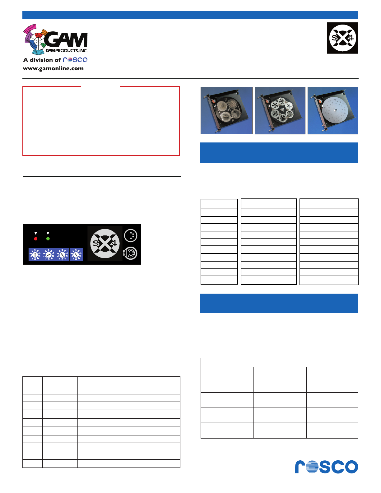
SX4® 4 & 6 GOBO TRAY • DISC TRAY (Modes 6 - 9)
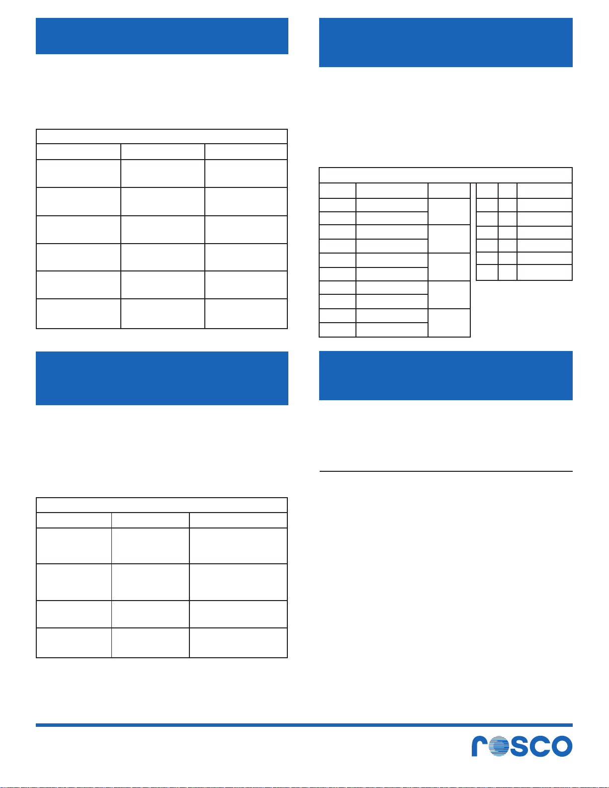
Four channel setting switches are on the control box.
The MODE switch to the far left.
Address then X10 and X100
Red
Green
X100
X1MODE X10
It is powered by 24 volt DC and controlled by
DMX512, either from most color scroller power supplies or a standalone power supply. Once powered,
the unit will show a red power LED to indicate the
power is on. The unit is also fitted with a green LED
which indicates the status of operation.
After it is powered, the unit needs to initialize to find
the home position of the gobos. This takes about 2
seconds during which time the green LED will flash.
Once the home sensing is complete the flashing will
stop. If the LED is not lit then DMX is not present. If
the LED continues flashing, it means there has been
a fault detecting the sensor and the unit operates but
without correct index positioning.
MODE DMX SETTING FUNCTION
0 0 Standlone: select one gobo for focus
1 1 DMX gobo select by fader
2 2 DMX gobo select speed & position
3 0 Standalone: speed, direction, timed
4 0 Standalone: 2 to 6 gobos, timed
5 0 Standalone: continuous rotate, set speed
6 1 DMX controlled rotation only
7 1 DMX control index / rotate one fader
8 2 DMX index/rotate on two faders
9 2 16 bit indexing / 10,000 positions
Set X1 Dial - This number is for gobo selection.
Each gobo is individually selected according to the
following table:
XI SIX-GOBO CHANGER FOUR-GOBO CHANGER
Selection Gobo Displayed Gobo Displayed
0,11 1 1
22 2 2
33 3 3
44 4 4
55 5 4
66 6 4
76 6 4
86 6 4
96 6 4
MODE 1 OPERATION • MODE SWITCH = 1
DMX Gobo Selector - One Channel Operation
Set DMX address on SX4® - This number is the desk
control (fader) channel. Gobo will change at the levels
shown in the charts below. Moves at maximum speed
and via the shortest route.
FOUR-GOBO CHANGER
Channel Level
100%
76%
51%
26%
0%
DMX Level
255
192
191
128
127
64
63
0
Four
Gobo 4
Gobo 3
Gobo 2
Gobo 1
Page 1 of 4
www.rosco.com
Page 2
MODE 1 OPERATION • MODE SWITCH = 1
DMX Gobo Selector - One Channel Operation
Set DMX address on SX4® - This number is the desk
control (fader) channel. Gobo will change at the
levels shown in the charts below. Moves at maximum
speed and via the shortest route.
SIX-GOBO CHANGER
Channel Level
100%
84%
67%
51%
34%
18%
0%
DMX Level
255
215
214
172
171
129
128
86
85
43
42
0
Six
Gobo 6
Gobo 5
Gobo 4
Gobo 3
Gobo 2
Gobo 1
MODE 3 OPERATION • MODE SWITCH = 3
Standalone operation displays all gobos
in sequence
• Use the X100 switch on the SX4® to set direction
and speed per chart below.
• Use the X10, X1 switch on the SX4® to set the
display time of each gobo. Setting these
switches from 1 to 99 varies the time in 0.1
second steps from 0.1 to 9.9 seconds.
FOUR & SIX GOBO CHANGER
X10
X1
X100
9
8
7
6
5
4
3
2
1
0
DIRECTION
Conterclockwise
Clockwise
Conterclockwise
Clockwise
Conterclockwise
Clockwise
Conterclockwise
Clockwise
Conterclockwise
SPEED
Very slow
Slow
Medium
Fast
Very fast
0
0
4
5
9
9
TIME (SECS)
0
1
2
0
8
9
0
1
2
0
8
9
MODE 2 OPERATION • MODE SWITCH = 2
DMX Gobo Select with Direction and Speed
Control - Two Channel Operation
Set DMX address on SX4® - This number is the desk
control (fader) channel
Channel 1: Gobo will change at the levels shown in
the charts as per Mode 1
Channel 2: Sets speed and direction per chart below
FOUR & SIX GOBO CHANGER
Channel Level
100%
76%
51%
26%
0%
DMX Level
255
192
191
128
127
64
63
0
Direction
Fast counterclockwise
Variable speed levels
Slow counterclockwise
Fast clockwise
Variable speed levels
Slow clockwise
Shortest route slow
Variable speed levels
Shortest route fast
MODE 4 OPERATION • MODE SWITCH = 4
Standalone operation for less than maximum
number of patterns
X1 switch on SX4® will set the display time each
gobo from 1 to 10 seconds.
• Set on 0 for 1 second
• Set on 9 for 10 seconds
X100 switch on SX4® selects the first position used
on the turret wheel.
X10 switch on SX4® selects the last position used
on the turret wheel.
If you have three patterns, you put them in positions
1,2 and 3. Adjust the X100 switch to 1 and the
X10 switch to 3 and the unit will auto select those
three positions only.
• If X100 = 1 and X10 = 3, the selection order is
1,2,3,2,1, etc
• If X100 = 2 and X10 = 5, the selection order is
2,3,4,5,4,3,2, etc
• If X100 = 5 and X10 = 2, the selection order is
5,6,1,2,1,6,5,6,1,2, etc
Page 2 of 4
www.rosco.com
Page 3

MODE 5 OPERATION • MODE SWITCH = 5
Standalone operation for continuous rotation
• X100 sets the direction - Select 1 for counter-
clockwise rotation or 2 for clockwise rotation
• X10, X1 sets speed of rotation - 00 is the slowest
and 63 is the fastest speed
MODE 6 OPERATION • MODE SWITCH = 6
Rotation DMX controlled only
MODE 8 OPERATION • MODE SWITCH = 8
DMX two channel indexing with variable
speed rotation
• Applies to single pattern disc effects and gobos
• Select DMX control channel on SX4® switches
X100, X10 and X1
Control channel fader has two functions:
• Operates as an indexing fader from zero to 99%
• If set at 100%, then it holds the disc in
continuous rotation mode
• Applies to single pattern disc effects.
• Select DMX control channel on SX4® switches
X100, X10 and X1
• Selected channel fader operates speed and
direction of rotation as per chart below
Channel Level
100%
51%
50%
49%
0%
DMX Level
255
129
128
127
0
Direction
Fast counterclockwise
Variable speed levels
Slow counterclockwise
STOPPED
Slow clockwise
Variable speed levels
Fast clockwise
MODE 7 OPERATION • MODE SWITCH = 7
DMX single channel linear indexing and
rotation control
• Applies to single pattern disc effects
• Select DMX control channel on SX4® switches
X100, X10 and X1
• Control channel fader operates index/rotate
functions as per chart below
Channel Level
100%
52%
51%
DMX Level
255
130
129
Direction
Slow clockwise
Variable speed levels
Continuous rotation
Fast clockwise
STOPPED
SETTING UP CHOICES FOR CHANNEL 1
Channel Level
100%
99%
0%
DMX Level
255
254
0
Direction
Continuous rotation mode
359 degrees
Variable index positions
0 degrees (home)
Second channel controls speed & direction of disc
when 1st channel is set at 100% continuous
rotation mode.
SECOND CHANNEL CONTROLS SPEED & DIRECTION OF DISC
PER CHART WHEN FIRST CHANNEL IS AT 100% CONTINOUS
ROTATION MODE
Channel Level
100%
51%
50%
49%
0%
SECOND CHANNEL CONTROLS SPEED & DIRECTION OF DISC
PER CHART WHEN 1ST CHANNEL IS SET FROM 0-9
INDEXING MODE
Channel Level
100%
51%
DMX Level
255
129
127, 128
126
0
DMX Level
255
128
Direction
Fast counterclockwise
Variable speed levels
Continuous rotation
Slow counterclockwise
STOPPED
Slow clockwise
Variable speed levels
Continuous rotation
Fast clockwise
Direction
Fast counterclockwise
Variable speed levels
indexing
Slow counterclockwise
50%
0%
Page 3 of 4
128
0
360 degrees
Indexing to position
with shortest route
maximum speed
0 degrees (home)
50%
1%
0%
127
1
0
Slow clockwise
Variable speed levels
Continuous rotation
Fast clockwise
Shortest route full speed
www.rosco.com
Page 4

MODE 9 OPERATION • MODE SWITCH = 9
DMX two channel highly accurate 16 bit linear indexing for all disc types
Select DMX control channel on SX4® switches - X100, X10, X1:
Use channel 1 for the whole degree positions and channel 2 for fine alignment positions between the single
degree settings of channel 1.
100%
100% = 359
Indexing
100%
100% = 1 Degree
Fine Indexing
Page 4 of 4
0%
Channel 1
COARSE POSITION
0 Degrees
0%
0 Degrees
Channel 1
FINE POSITION
www.rosco.com
 Loading...