

Page 1

Service Manual
200MB
Page 2

Table of Contents
Operating Instructions 3
Turn On / Calibration Procedure 6
Schematics 9
Engineering Change Orders (ECOs) 18
Bill of Materials 19
Page 3
Page 4
Page 5
Page 6

200MB/RCB T/O Procedure
Rev.B- 3/7/88
1) Inspect board.
2) Connect mains.
3) Observe the following:
A) no load E) volume on 0 I) chorus depth on 0
B) variac at 0 F) master on 0 J) chorus rate on 0
C) trim pots halfway G) switches outK) speaker on
D) tones on 5 H) sustain on 0
4) Gradually adjust variac to 25 Vrms.
U20/P4= -1.5V (+or-)-.5V. U20/P8= 3.2V (+or-) -.5V.
Regulated supplies = -.5 V (+or-) .5V./ 7.1V (+or-) -.5V.
5) Gradually adjust variac to 70Vrms while listening to the speaker and watching variac (AC amps)
and scope. Output should go –8V then +10V , motor a little and settle at 0 between 50-60V rms.
Regulated supplies = -14.3V (+or-) .5V/ 14.2V (+or-) .5V.
6) Adjust variac to 120V rms and turn speaker off. Supply voltage (+or-)46.5V (+or -).5V.
7) Set bias. Adjust R207 to get 5mV across R197, R208 ( most pos. of the two), and R223, R224
(the most neg. of the two).
8) Set the following: master on 10.
9) Connect sine input (400Hz 50mVrms) –26 dB.
10) Compressor test.
A) V olume on 10.
B ) Sustain on 0. U2/P6= 700mVp-p. U4/P7= 2.3Vp-p.
C) Engage compressor. U4/P7= 1.2Vp-p.
D) Gradually adjust sustain to 10. U4/P7 should increase to 1.7Vp-p.
E) Disengage compressor and continue.
11) Limiter adjustment. Adjust R174 to get a flat response at U21/P2 (compare fig.)
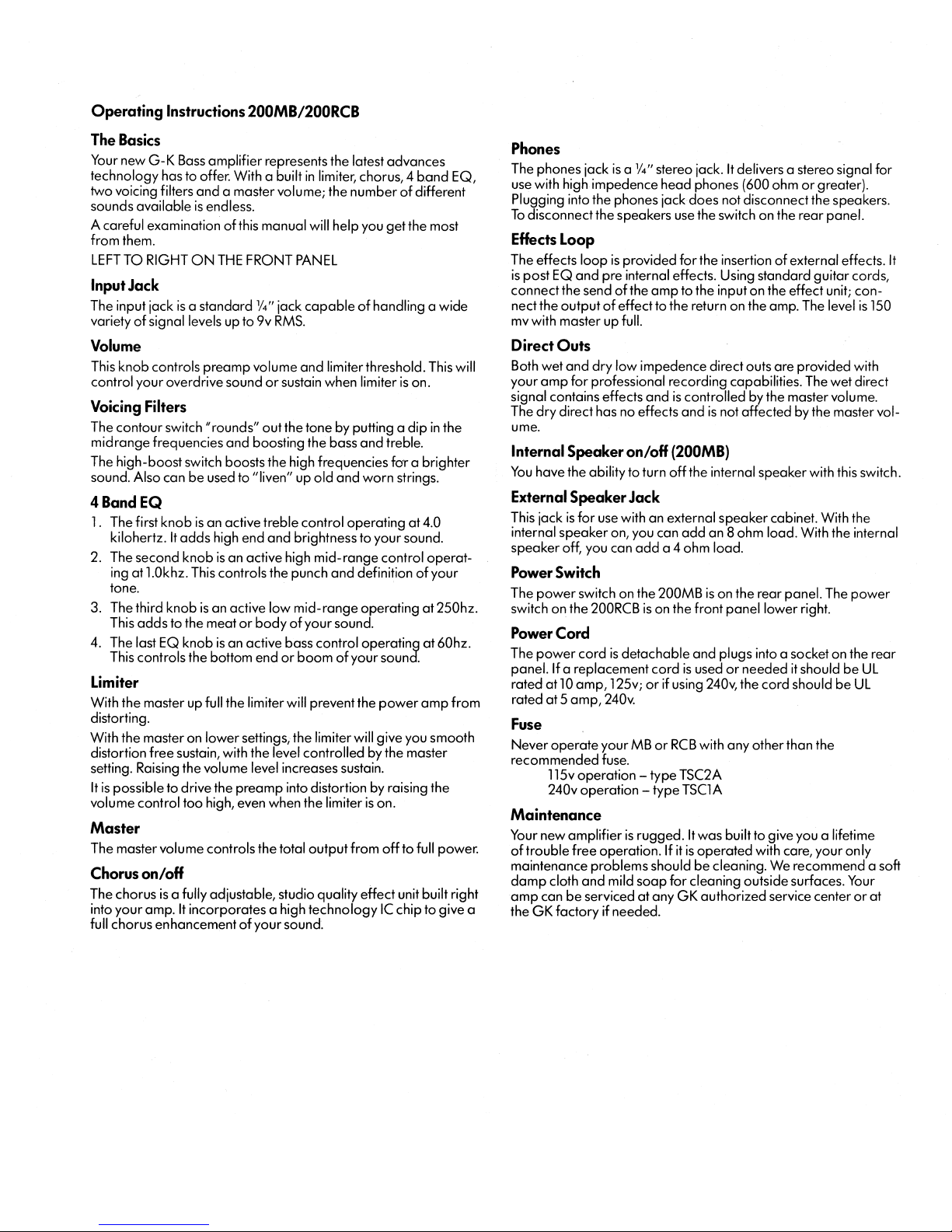
12) Set the following: volume on 0; 4 ohm load.
13) Slowly turn up volume just until limiter LED begins to light. At this point, output should be at full
power =20V rms.
14) Current limiter test. Change to a 2 ohm load. Output should be a clean sine wave without clipping
and = 12Vrms (+or-) .5V rms.
15) Turn master up and down to check if it works properly .
16) Set the following: volume and master on 10, no load.
17) Check direct out (J5) pins 2 and 3 = 550mV rms (1.5Vp-p).
18) Check balance out left ( J8) and right (J9). Both should = 5.5V rms in stereo and mono mode at pins
2 and 3.
19) Check send (J7). 1.7Vp-p, clean sine wave. Probe at R229.
20) Check headphone jack (J3). Tip = 3.4V rms / Ring = 3.4V rms or 13Vp-p clipped.
21) Test return.
A) Plug input into return (6). (400Hz 50mV rms sine) –26.0 dB. Output = 4Vrms.
B) Line out (J10)= 80mV rms.
22) Change to square signal at input (400Hz –26.0dB).
23) Test tones and filters and compare figures.
24) Chorus test.
Page 7

Note: Trigger is on the channel, the scope probe is on, and connect to D.0 (J5) @ 1V/div . This will make it
possible to make measurements without having trigger problems. An external trigger could also be used.
A) Volume at 9 o’clock
B ) Master at 10.
C) Tones on 5.
D) Engage chorus.
E ) Rate 0/ Depth 0. Deviation = 1.3 sec. / Rate = 1.5 sec.
F) Rate 0/ Depth 10. Deviation = 5.0 sec.
G) Rate 10/ Depth 10. Rate = .25 sec.
H) Disengage chorus.
25) Balance out test. Sine input (400Hz 50mVrms) –26.0dB.
A) V olume on 5.
B ) Master on 10.
C) Tones on 5. Balance out left pins 2 and 3 and balance out right pins should look different. Left
should swell up and down to a min. and max. value. Right should do the same, however
oscillate right and left.
D) Engage chorus.
E ) Stereo switch out.
F) Push in stereo switch (mono mode). Signal on left and right should look similar, swelling up and
down.
G) Chorus off.
26) Check speaker cut-off switch.
27) Disconnect input.
28) Proceed with noise and tap test.
A) Controls on 10, switch out = noise <60mV rms.
B ) Controls on 10, contour in = noise <80mV rms.
C) Controls on 10, comp. in, sustain 0 = noise < 50mVrms.
D) Controls on 10, comp. in, sustain 10 = noise< 250mV rms.
E ) Controls on 10, comp. in, sustain 10 = noise< 300mVrms.
F) Contour in, chorus in = noise< 40mVrms.
G) Contour in, master on 0= noise< 2.5mVrms.
Noise should be clean without popping or cracking.
Page 8

Page 9

Page 10

Page 11

Page 12

Page 13

Page 14

Page 15

Page 16

Page 17

Page 18

Page 19

SW- Rev. 8/27/99 200MB INDENTED BILL OF MA TERIALS
NOTE: Level 1 refers to main assembly parts.
LVL PART# DESCRIPTION QTY REF. DESIG.
1 010-0012-0 MPSA06 NPN 80V 500MA TO-92 1
1 011-0023-0 TIP29C NPN 100V 1A TO-220 FP 1
1 011-1035-0 TIP30C PNP 100V 1A TO-220 1
1 012-0084-0 TIP 33CFP NPN 100V 10A TO218 2
1 012-1085-0 TIP 34CFP ,PNP,100V,10A,T O-218,PECOR 2
1 025-0116-0 RED LED,1.5MCD,120 DEG,T-1 2
Level 2 refers to board level components.
Main assembly numbers are in bold face, while commonly
needed parts are italicized.
1 080-0061-0 TRANSFORMER,100W,120V 1
1 082-0039-0 SPEAKER,12",80W,Z=8,PYLE FOAM EDGE 1
1 091-0003-0 FUSE, 3A,125V,1/4X1 1/4,SLB 1
2 799-TEST-0 TRY OUT 0
1 092-0009-0 XLR,MALE,PC TERM TRIANGLE 3
1 093-0014-0 RECEPTICAL AC,Q-TERM 1
1 093-0032-0 HOUSING,3X.156,FEMALE 22GA,LOCK 2
1 094-0013-0 HOLDER,FUSE,1/4 X 1 1/4,Q-TERM 1
1 094-0019-0 SOLDER LUG,#6 1
1 095-0005-0 POWER CORD,117V PLUG,DETACH 1
1 100-0012-0 GROMIT ,3/16 X.100 1
1 100-0016-0 LOGO,3 INCH,CAST 1
1 100-0027-0 BUTTON,ROUND BLACK CAP - PUSH SWITCH 1
1 100-0030-0 BUTTON,RECT BLACK CAP - PUSH SWITCH 1
1 100-0037-0 HEAT CL IP,T O-98 1
1 100-0042-0 HANDLE,RUBBER,6.5" 1
1 100-0044-0 BUMPER,1/2",SQUARE 2
1 100-0057-0 KNOB BODY 18 SPLINE SHAFT 9
1 100-0062-0 KNOB CAP GRAY,FOR 100-0057 9
1 100-0065-0 CAP FOR 6.5" HANDLE “BLACK” 2
1 100-0076-0 FOOT ,RUBBER,ROUND,5/8DIA. X 5/8" 4
1 111-0061-0 BOLT 4-40 3/8 PHP CAD 4
1 111-0081-0 BOLT 4-40 1/2 PHP CAD 6
1 111-3041-0 SCREW 4AB 1/4 PHP CAD 6
Page 20

LVL PART# DESCRIPTION QTY REF. DESIG.
1 111-6001-0 NUT 4-40 KEP SMALL 4
1 111-6011-0 NUT 4-40 HEX SMALL CAD 6
1 111-7011-0 WASHER #4 SPLIT 6
1 112-0051-0 BOLT 6-32 5/16 PHP CAD 4
1 112-1050-0 BOLT 6-32 5/16 FHP 82^ B.O. 11
1 112-1 120-0 BOLT 6-32 3/4 FHP 82^ B.O. 8
1 112-4080-0 SCREW 6AB 1/2 FHP 82^ B.O. 38
1 112-4081-0 SCREW 6AB 1/2 FHP 82^ CAD 1
1 112-4140-0 SCREW 6AB 7/8 FHP 82^ B.O. 1
1 112-6001-0 NUT 6-32 KEP LARG SIZE CAD 8
1 112-7001-0 WASHER #6 FLA T CAD 12
1 113-0080-0 BOLT 8-32 1/2 PHP B.O. 4
1 113-6011-0 NUT 8-32 KEP CAD 4
1 114-0080-0 BOLT 10-32 1/2 PHP B.O. 2
1 115-7005-0 WASHER 3/8 FIBRE FLA T 1
1 115-7021-0 WASHER 3/8 INTERNAL CAD 12
1 115-7031-0 WASHER SMALL 3/8 LOCK CAD 3
1 132-0349-A 200MK/MV TOP COVER 1
2 120-0005-0 ALUM .100 98
1 132-0350-B 200MB-MK RIGHT SIDE 1
2 114-6046-0 NUT 10-32 CAPTIVE 1
2 120-0005-0 ALUM .100 164
1 132-0351-B 200MB-MK LEFT SIDE 1
2 114-6046-0 NUT 10-32 CAPTIVE 1
2 120-0005-0 ALUM .100 164
1 132-0352-B 200MB BAFFLE 1
2 120-0005-0 ALUM .100 384
1 132-0356-B 200MK GRILL 1
2 120-0003-0 STEEL,16GA,PERF ,3’X10’X.060 0
2 120-0011-0 STEEL,18 GAUGE JET COAT,.048 272
1 132-0384-B 200MB FRONT PANEL SERIES 2 1
2 112-6016-0 NUT 6-32 CAPTIVE 5
2 120-0007-0 ALUM .063 54
Page 21

LVL PART# DESCRIPTION QTY REF. DESIG.
1 132-0385-B 200MB REAR PANEL SERIES 2 1
2 112-6016-0 NUT 6-32 CAPTIVE 10
2 120-0005-0 ALUM .100 45
1 132-0386-D 200MB BACK SERIES 2 1
2 120-0005-0 ALUM .100 406
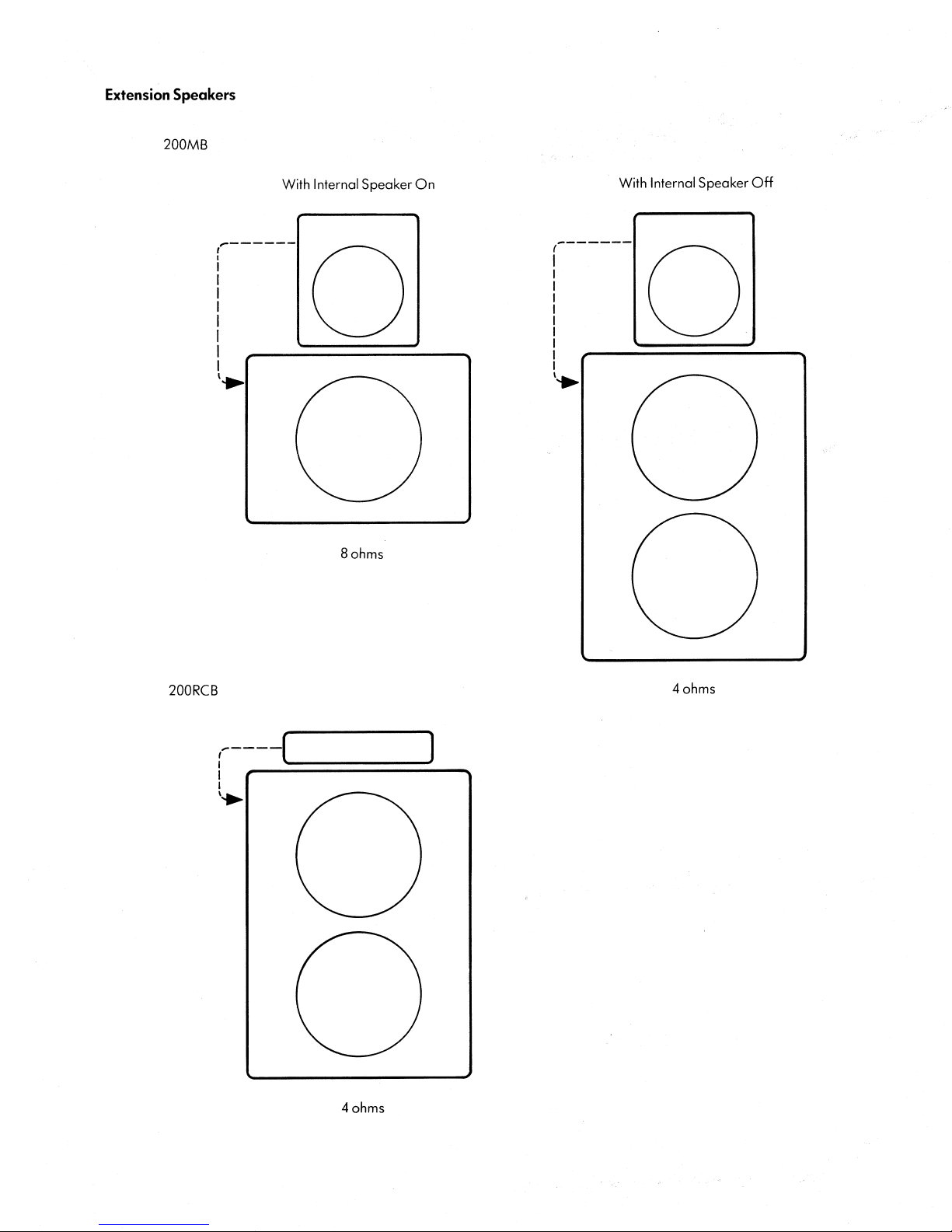
1 160-0008-0 MANUAL,MB-RCB SERIES II 1
1 202-0014-0 200MB WIRE KIT 1
1 206-0056-G 200MB-RCB II AMP 1
2 001-0006-0 MN3007 1024 STAGE BBD 1
2 001-1030-0 LF353N DUAL JFET OP AMP 13 U1,3,5,6,7,8,9,11,17,18,20,21,22
2 001-1038-0 LM386 LOW VOLT AGE POWER AMP 2 U12,13
2 001-2009-0 LM556CN DUAL TIMER 1 U14
2 001-3028-0 TL604 DUAL COMP ANALOG SWITCH 2 U4,10
2 001-4043-0 NE571 DUAL COMP ANDOR 2
2 002-0034-0 CD4013 DUAL D FLIP-FLOP 1 U15
2 010-0012-0 MPSA06 NPN 80V 500MA TO-92 5 Q0,4,6,7,14
2 010-1013-0 MPSA56 PNP 80V 500MA TO-92 5 Q3,5,12,16,18
2 010-2010-0 J113 N-JFET 35V 2MA T O-92 2 Q1,2
2 011-0023-0 TIP29C NPN 100V 1A TO-220 FP 1 Q8
2 011-1035-0 TIP30C PNP 100V 1A TO-220 2 Q9,18
2 020-0036-0 1N747A,ZENER,3.6V,5%,400MW,DO-35 2 D3,4
2 020-0120-0 1N759A,ZENER,12V ,5%,400MW,DO-35 6 D1,2,6,7,10,11
2 020-0160-0 1N966B,ZENER,16V,5%,400MW,DO-35 2 D21,23
2 020-1103-0 1N914 ,RECT-FAST ,200MA,100V,4NS,DO-35 6 D5,12,13,14,15,16
2 020-2105-0 1N4002,RECT,1A,150V,DO-41 5 D17,18,19,20,24
2 023-0109-0 KBPC-102 BRIDGE RECT 3A,200V ,C219K 1 BRIDGE RECTIFIER
2 030-1103-0 CAP,CERAMIC AXIAL,103,30%,25V 1 1 C12,23,27,34,38,39,74,86,95,100,102
2 030-2101-0 CAP,CERAMIC AXIAL,101,5%,50V 8 C1,5,32,36,43,48,52,87
2 030-2102-0 CAP,CERAMIC AXIAL,102,10%,50V 1 C63
2 030-2104-0 CAP,CERAMIC AXIAL,104,10%,50V ,XR7,.3" 7
2 030-2222-0 CAP,CERAMIC AXIAL,222,10%,50V 10 C17,18,25,33,35,68,70,71,98,101
2 030-2224-0 CAP,CERAMIC AXIAL,224,20%,50V ,XR7 4 C30,37,40,44
2 030-2271-0 CAP,CERAMIC AXIAL,271,10%,50V 5 C21,29,69,72,94
Page 22

LVL PART# DESCRIPTION QTY REF. DESIG.
2 030-2332-0 CAP,CERAMIC AXIAL,332,10%,50V 1 C28
2 030-2470-0 CAP,CERAMIC AXIAL,47,5%,50V 1 C79A
2 030-2473-0 CAP,CERAMIC AXIAL XR7,473,10%,50V 2 C61,64
2 030-2474-0 CAP,CERAMIC AXIAL Z5U,474,20%,50V 3 C31,45,49
2 030-2561-0 CAP,CERAMIC AXIAL,561,10%,50V 1 C2
2 031-1227-0 CAP,ELECTROLYTIC RADIAL,227,-10%+50%,25V 10 C3,42,55,57,58,59,60,88,99,103
2 031-2106-0 CAP,ELECTROLYTIC RADIAL,106,-10%+50%,50V 2 C90,91
2 031-2227-0 CAP,ELECTROLYTIC RADIAL,227,-10%+50%,50V 1 C96
2 031-2335-0 CAP,ELECTROL YTIC RADIAL,335,20%,50V 32 C4,6,7,8,9,10,11,13,14,15,16,19,20,22,24,26,46,47,
2 038-2335-0 CAP,ELECTROLITIC AXIAL TR 335,20% 25V 7
2 038-2478-0 CAP,ELECTROL YTIC AXIAL,478,20%,50V 2 C92,93
2 051-0100-0 RES,CARBON FILM,1 OHM,1/4W,5% 40 R4,14,15,23,25,26,37,46,53,67,73,74,75,77,78,84,
2 051-0101-0 RES,CARBON FILM,10 OHM,1/4W,5% 7 R87,120,127,128,129,131,198
2 051-0470-0 RES,CARBON FILM, 4.7 OHM,1/4W,5% 2 R212,221
2 051-1001-0 RES,CARBON FILM,100 OHM,1/4W,5% 2 R200,215
2 051-1002-0 RES,CARBON FILM,1K OHM,1/4W,5% 1 1 R6,76,101,113,126,130,143,162,167,179,206
2 051-1004-0 RES,CARBON FILM,100K OHM,1/4W,5% 1 1 R7,43,105,110,135,136,140,164,165,183,183A
2 051-1005-0 RES,CARBON FILM,1M OHM,1/4W,5% 5 R2,86,91,171,184
2 051-1203-0 RES,CARBON FILM,12K OHM,1/4W,5% 23 R5,30,55,59,60,61,81,82,83,115,119,123,125,134,
2 051-1204-0 RES,CARBON FILM,120K OHM,1/4W,5% 3 R48,139,227
2 051-2202-0 RES,CARBON FILM,2.2K OHM,1/4W,5% 11 R28,88,100,102,103,118,124,169,204,220,228
50,51,54,66,67,73,75,76,77,78,79,80,81,82,83,85,
89,91,104,105,66A
85,93,95,96,99,108,121,122,133,141,148,153,154,
155,156,157,158,163,191,196,214,216,229,230
142,146,150,161
2 051-2203-0 RES,CARBON FILM,22K OHM,1/4W,5% 24 R8,10,11,13,20,21,22,24,27,33,34,35,45,50,
2 051-2204-0 RES,CARBON FILM,220K OHM,1/4W,5% 1 1 R38,54,58,62,65,71,80,189,190,193,194
2 051-2206-0 RES,CARBON FILM,22M OHM,1/4W,5% 2 R16,19
0.2 051-3302-0 RES,CARBON FILM,3.3K OHM,1/4W,5% 8 R3,36,116,117,132,203,205,222
0.2 051-3303-0 RES,CARBON FILM,33K OHM,1/4W,5% 10 R1,32,42,52,79,106,107,109,111,149
2 051-3304-0 RES,CARBON FILM,330K OHM,1/4W,5% 2 R51,172
2 051-4701-0 RES,CARBON FILM,470 OHM,1/4W,5% 5 R192,195,199,201,202
2 051-4702-0 RES,CARBON FILM,4.7K OHM,1/4W,5% 2 R180,182
2 051-4703-0 RES,CARBON FILM,47K OHM,1/4W,5% 10 R17,18,31,63,69,104,112,144,145,175
90,92,94,97,147,152,166,178,213,219
Page 23

LVL PART# DESCRIPTION QTY REF. DESIG.
2 051-5602-0 RES,CARBON FILM,5.6K OHM,1/4W,5% 10 R47,56,66,68,70,137,138,170,173,185
2 051-5603-0 RES,CARBON FILM,56K OHM,1/4W,5% 7 R9,39,40,41,44,151,177
2 052-0000-0 RES,METAL WIRE, 0 OHM,1/4W ,1% 5
2 052-1213-0 RES,METAL FILM,12.1K OHM,1/4W ,1% 12 R159,160,225,226,231,232,233,234,
2 054-2702-0 RES,CARBON FILM,2.7K OHM,1W,5% 4 R168,209,210,218
2 056-.330-0 RES,CERAMIC WW,.33 OHM,5W,10% 4 R197,208,223,224
2 056-0500-0 RES,CERAMIC WW,5 OHM,5W ,10% 1 R211
2 070-0501-0 POT,2X50KB,9MM,PLAST KNURL 14MM,.05W 1 R114
235,236,237,238
2 070-0506-0 POT,50KA,9MM,PLASTIC KNURL 14MM,.05W 1 R12-volume
2 070-0508-0 POT,1K TRIM,6MM,SLOT ,.3W 1 R207
2 070-0509-0 POT,20K TRIM,6MM,SLOT ,.3W 1 R174
2 070-0514-0 POT,50KB,LINEAR,9MM,METAL KNURL 9MM,.1 7 R72,88,96,107,120,134,151-all other pots
2 090-0010-0 SWITCH,PP ,DPDT ,6A,PC TERM 1 S5
2 090-0012-0 SWITCH,MINI PP,DPDT,.1A BRK/MAKE,PC TER 5 S1,2,3,4,7
2 090-0013-0 SWITCH,PP,DPDT,.2A,PC MOUNT 1 S6
2 092-0201-0 JACK SW-RN112APC,1/4",S-TIP,SLDR TERM 2 J1,6-input
2 092-0202-0 JACK SW-RN114BPC,1/4",S-TIP,S-RING,P .C. 1 J2
2 092-0203-0 JACK SW-RN1 11PC,1/4",O-TIP,P .C. TERM 3 J4,7,10
2 092-0204-0 JACK SW-RN112BPC,1/4",O-TIP,O-RING,P .C. 1 J3
2 093-0028-0 HEADER,3X.156,MALE,LOCK 2 FOR POWER AND SPEAKER CUT-OFF
2 100-0028-0 BUTTON,SQUARE BLACK CAP - MINI SWITCH 5
2 145-0056-G 200MB BOARD 1 P .C.B.
1 602-0007-0 FORMS,WARRANTY CARDS 1
 Loading...