

Page 1
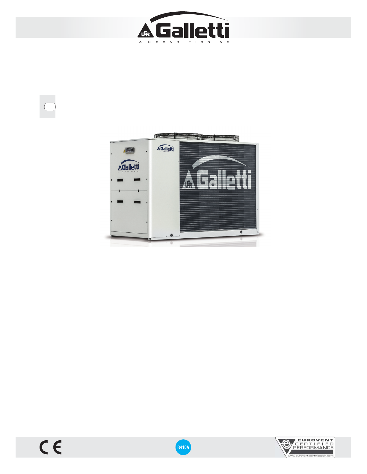
MPE
4 kW - 76 kW
INSTALLATION, USE AND MAINTENANCE MANUAL
GB
Page 2

MPE
2
All copying, even partial, of this manual is strictly forbidden RG66007169 - Rev 00
1 THE MPE SERIES ................................................................................... 5
1.1 Field of application
................................................................................ 5
1.2 Models and versions
.............................................................................. 5
1.3 Components lay-out
............................................................................... 6
1.4 Water circuits
...................................................................................... 13
2 INSPECTION, CONVEYANCE DIMENSIONAL AND SITING
..................... 15
2.1 Inspection
............................................................................................ 15
2.2 Conveyance
......................................................................................... 15
2.3 Dimensional
......................................................................................... 16
2.4 Siting
................................................................................................... 22
2.4.1 Installation clearance requirements
........................................................ 22
2.5 Dampers siting
.................................................................................... 23
3 PLUMBING AND ELECTRICAL CONNECTIONS
...................................... 24
3.1 Plumbing connection
........................................................................... 24
3.1.1 Hydraulic connection
............................................................................ 24
3.1.2 Recommended water circuit
.................................................................. 24
3.1.3 Filling the system
.................................................................................. 25
3.2 Electrical connections
.......................................................................... 26
3.3 Electrical data
...................................................................................... 27
4 STARTING UP
....................................................................................... 29
4.1 Preliminary checks
.............................................................................. 29
5 MICROPROCESSOR CONTROL
............................................................. 30
5.1 Description of control panel
................................................................. 30
5.1.1 Remote control panels (accessories)
..................................................... 30
5.1.2 Main functions
...................................................................................... 30
5.1.3 Devices controlled
................................................................................ 30
5.2 Using the control panel
........................................................................ 30
5.2.1 Display
................................................................................................. 30
5.2.2 Information about equipment status
....................................................... 31
5.3 Switching on and off and changing the operating mode
...................... 31
5.3.1 Switching the unit on and off in the cooling mode
.................................. 31
5.3.2 Switching the unit on and off in the heating mode
(MPE H heat pump model only)
............................................................ 31
5.3.3 Switching on and off and changing the operating mode
......................... 31
5.3.4 Changing the operating mode from the keyboard on the unit
.................. 31
5.4 Display and setting of operating parameters
....................................... 32
5.4.1 Parameters
........................................................................................... 32
5.5 Regulation logic
................................................................................... 32
5.6 Set point compensation
....................................................................... 33
5.7 Signals and alarms
.............................................................................. 34
5.7.1 Alarm reset
........................................................................................... 34
6 OPERATING LIMITS
.............................................................................. 35
6.1 Operating limits in chiller mode
........................................................... 35
6.2 Operating limits in heat pump mode
.................................................... 36
6.3 Thermal carrying fluid
......................................................................... 36
7 CONTROL AND SAFETY DEVICES
......................................................... 37
7.1 Control devices
.................................................................................... 37
7.1.1 Service thermostat
................................................................................ 37
7.1.2 Control device settings
.......................................................................... 37
7.2 Safety devices
..................................................................................... 37
7.2.1 High pressure switch
............................................................................ 37
7.2.2 Refrigerant circuit safety valve
............................................................... 37
7.2.3 Low pressure switch
............................................................................. 37
7.2.4 Anti-recycle timer
.................................................................................. 37
7.2.5 Antifreeze thermostat
............................................................................ 37
7.2.6 Water differential pressure switch
.......................................................... 37
7.2.7 Water safety valve
................................................................................. 37
7.2.8 Safety device settings
........................................................................... 37
8 ROUTINE MAINTENANCE AND CHECKS
............................................... 38
8.1 Checks to be performed by the user
.................................................... 38
8.2 Checks and maintenance to be performed by
specialised personnel
.......................................................................... 38
9 RETIRING THE UNIT
............................................................................. 38
10 TECHNICAL FEATURES
........................................................................ 39
10.1 Water chillers rated technical data
...................................................... 39
10.2 Heat pumps rated technical data
......................................................... 40
11 COOLING CIRCUITS
............................................................................. 43
12 TROUBLESHOOTING
............................................................................ 52
TRANSLATION OF ORIGINAL INSTRUCTIONS
The technical and dimensional data reported in this manual may be modified in view
of any product improvement.
WATER CHILLERS AND HEAT PUMPS ARE IN ACORDARCE WITH THE
LAW 97/23/CE (PED) FILLING IN D1 FORM, APPROVED BY THE THIRD
NOTIFIED BODY ICIM N°0425.
Page 3
3
All copying, even partial, of this manual is strictly forbiddenRG66007169 - Rev 00
Serial number
Code
Date of production
Cooling capacity (W)
Heating capacity (W)
Power supply
Power input (kW)
Weight (kg)
Max power input (kW)
Max running amperage (A)
HP Power input (kW)
Refrigerant
Max refrigerant pressure (bar)
Max refrigerant temperature (°C)
Made in Italy
CATEGORIA 1
Galletti S.p.A. via L.Romagnoli 12/a
40010 Bentivoglio (BO) Italia
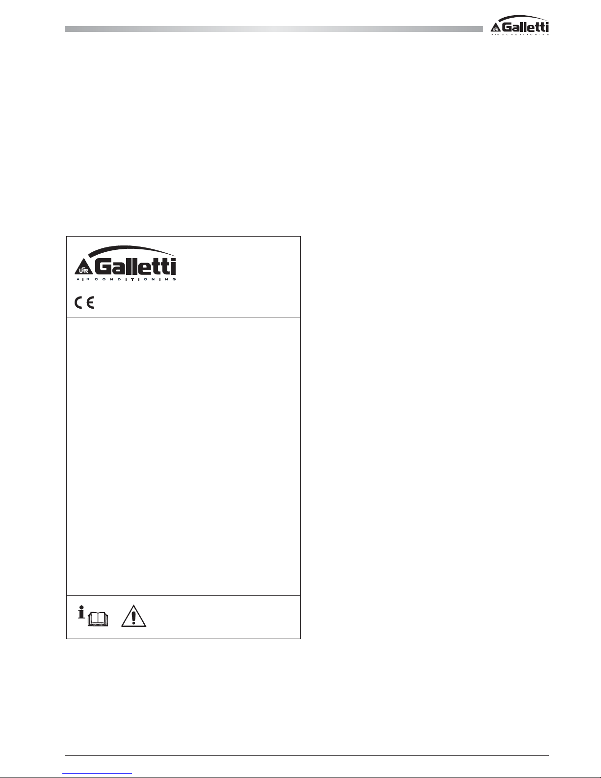
The unit data are reported on the rating label in this page.
THE LABEL SHOWS THE FOLLOWING DATA:
- Series and size of the unit
- Date of manufacture
- Main technical data
- Manufacturer
- The label is applied on the unit, usually on the enclosing panels beside the condenser coil
IMPORTANT: NEVER REMOVE THE LABEL
- Serial number of the unit
- The serial number permits to identify the technical characteristics and the components installed
- Without this datum it will be impossible to identify the unit correctly
Page 4
MPE
4
All copying, even partial, of this manual is strictly forbidden RG66007169 - Rev 00
GENERAL CAUTIONARY NOTES
- Keep this manual intact in a safe place for the all life of the unit.
- Carefully read all the information contained in this manual, paying special attention to sections marked "Important" and "Warning"; failure to comply with
the instructions provided could result in injury to persons or damage to the equipment.
- Should a fault occur, consult this manual and if necessary contact the nearest Galletti S.p.A. service centre.
- All installation and maintenance operations must be carried out by qualified personnel, unless otherwise indicated in this manual.
- THE FIRST START UP MUST BE CARRIED OUT EXCLUSIVELY BY QUALIFIED PERSONNEL AND AUTHORIZED BY GALLETTI SPA
(SEE WARRANTY SHEET ATTACHED).
- Before performing any work on the unit, disconnect it from the power supply.
- Failure to comply with the rules provided in this manual will result in the immediate invalidation of the warranty.
- Galletti S.p.A. shall not accept any liability for injury or damage resulting from improper use of the equipment or failure to comply with the directions
provided in this manual and on the unit itself.
- For further information or communication, please contact the company at: [email protected]
- To find out the weight of each unit, please refer to the table in the paragraph “Rated specifications”
SAFETY SYMBOLS
Read the manual carefully
WARNING
Use personal protective
equipment
USE SUITABLE PPE (GLOVES FOR REFRIGERANT, PROTECTIVE GOGGLES).
Page 5
5
All copying, even partial, of this manual is strictly forbiddenRG66007169 - Rev 00
1 THE MPE SERIES
1.1 FIELD OF APPLICATION
MPE air-condensed water chillers and heat pumps have been designed to cool and heat water for air conditioning and heating systems in residential or
commercial buildings. The MPE range units are intended for outdoor installation (IP24 protection degree), in a position not accessible to the public. If
protection grids are not provided (accessory) and if the machine can be reached by non-specialised personnel, access to the finned coil must be prohibited
using appropriate barriers. Do not install the unit in environments with gas or flammable dusts.
1.2 MODELS AND VERSIONS
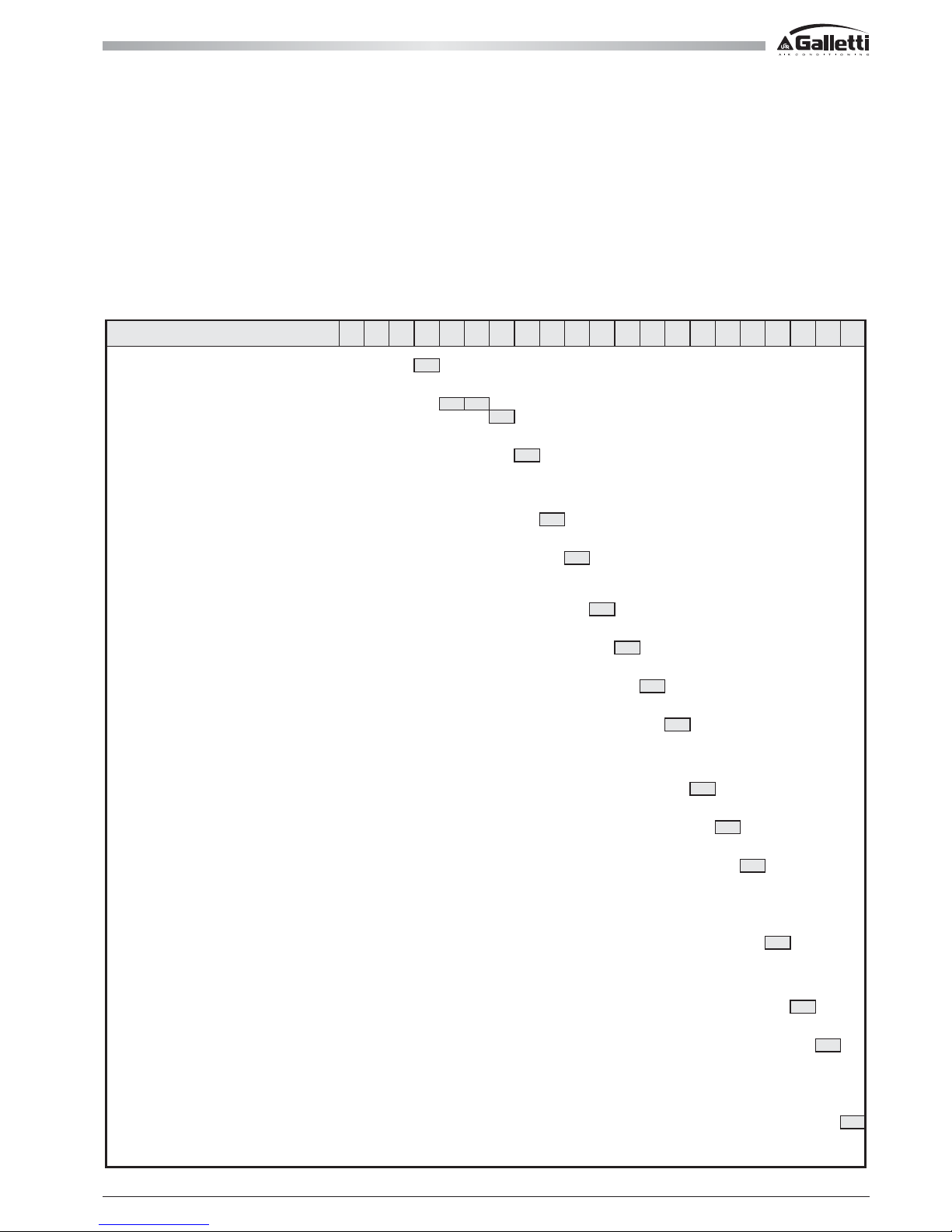
The MPE series includes 27 models with different in cooling only and heat pump version: All models are charged with R410A refrigerant.
The choice of some options can prevent the choice of some options or oblige the selection of other fields. To contact the Galletti for verification
Complete Unit Code MPE009C00000000000001
Version 0
Single compressor
0
Ta nd em T
Model (size) 0 9
Operation
C
Chiller
C
Heat pump H
Power Supply 0
Standard 400 - 3N - 50
0
Single phase M
400 - 3N - 50 + thermalmagnetic 2
Single Phase + thermalmagnetic 4
Expansion Valve 0
Standard valve
0
Electronic expansion valve A
Pump and accessories 0
Not present
0
Pump - vessel - water charge valve 1
Double pump - vessel - water charge valve 2
Buffer tank 0
Not present
0
Present S
Heat Recover (cooling only models) 0
Not present
0
Present with contact for pump D
Condensing control 0
Not present
0
With modulating air flow C
Antifreeze kit 0
Not present
0
Present, standard unit E
Present, unit with pump and vessel P
Present, unit with pump, vessel and tank S
Acoustic insulation 0
Not present
0
Sound proofing insulation for compressor housing 1
Refrigerant circuit accessoires 0
Not present
0
Refrigerant gauge M
Remote control 0
Not present
0
RS485 port (modbus + carel protocol) 2
Simplified S
Base microprocessor remote control (modbus excluded ) M
ADVANCED microprocessor remote control X
Special coil 0
Standard
O
Copper / copper heat exchanger R
Cataphoresis C
“Blygold” B
Protection grille 0
Not present
0
Present G
Compressor options 0
Not present
0
Power factor correction capacitors 1
Soft starter 2
Power factor correction capacitors + soft starter
3
Low temperature air water pressure switch carter heater (chiller), coil cable (PDC) 4
Control panel 1
Basic microprocessor
1
Advanced microprocessor (not available for models 04 ~ 08) 2
Page 6
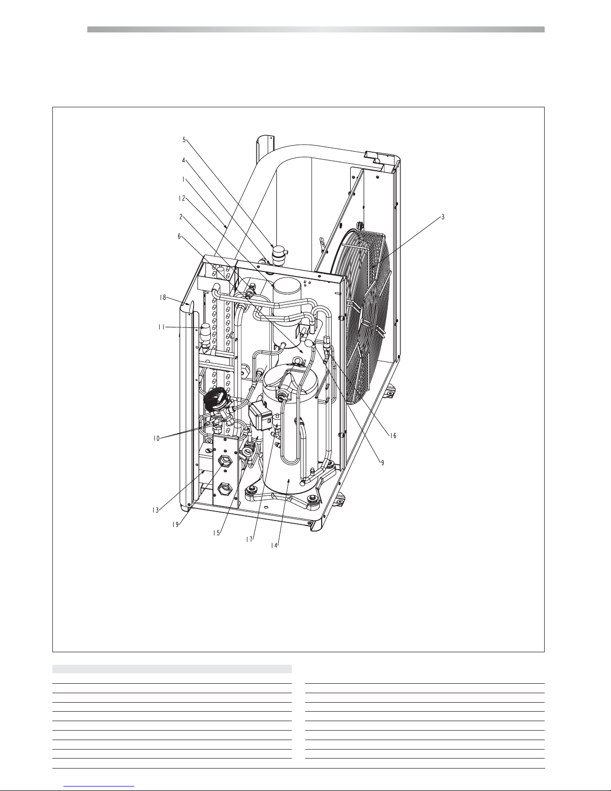
MPE
6
MPE 04 ÷ 08
All copying, even partial, of this manual is strictly forbidden RG66007169 - Rev 00
1 THE MPE SERIES
1.3 COMPONENTS LAY-OUT
DESCRIPTION
1. R410A-air heat-exchanger
2. R410A-water heat-exchanger
3. Fans
4. Water differential pressure switch (fan housing)
5. Automatic air purge valve
6. Expansion vessel (fan housing)
7. Water tank (accessory)
9. 4-way valve (MPE H)
10. Thermostatic valve
11. Water safety valve
12. Liquid receiver
13. Pump
14. Compressor
15. Refrigerant filter
16. Low pressure switch and charge port
17. High pressure switch and charge port
18. Water gauge
19. Water charge
Page 7
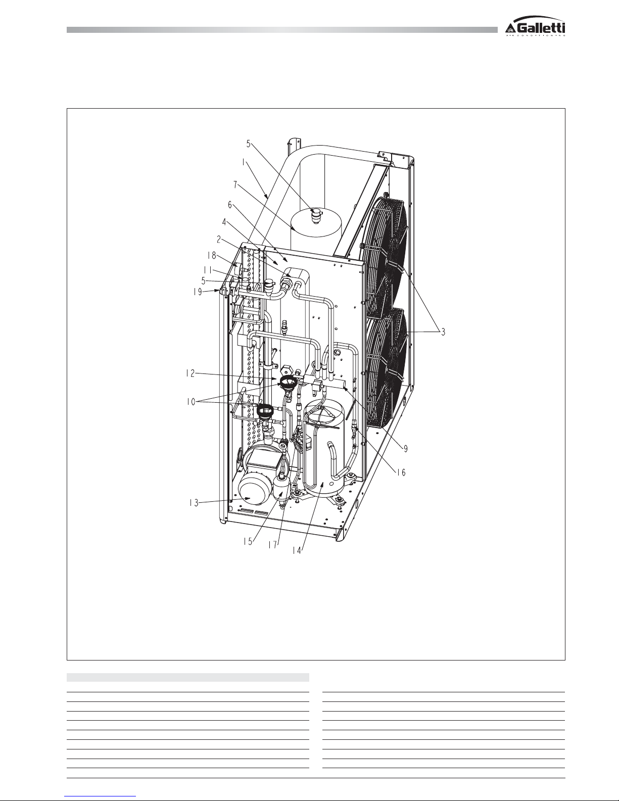
7
MPE 10 ÷ 15
All copying, even partial, of this manual is strictly forbiddenRG66007169 - Rev 00
1 THE MPE SERIES
1.3 COMPONENTS LAY-OUT
DESCRIPTION
1. R410A-air heat-exchanger
2. R410A-water heat-exchanger
3. Fans
4. Water differential pressure switch (fan housing)
5. Automatic air purge valve
6. Expansion vessel (fan housing)
7. Water tank (accessory)
9. 4-way valve (MPE H)
10. Thermostatic valve
11. Water safety valve
12. Liquid receiver (fan housing)
13. Pump
14. Compressor
15. Refrigerant filter
16. Low pressure switch and charge port
17. High pressure switch and charge port
18. Water gauge
19. Water charge
Page 8
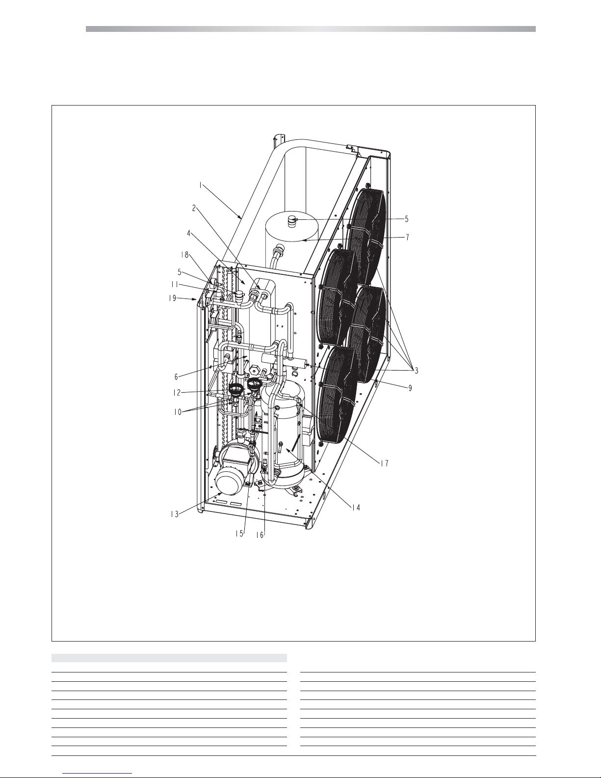
MPE
8
MPE 18 ÷ 27
All copying, even partial, of this manual is strictly forbidden RG66007169 - Rev 00
1 THE MPE SERIES
1.3 COMPONENTS LAY-OUT
DESCRIPTION
1. R410A-air heat-exchanger
2. R410A-water heat-exchanger
3. Fans
4. Water differential pressure switch (fan housing)
5. Automatic air purge valve
6. Expansion vessel (fan housing)
7. Water tank (accessory)
9. 4-way valve (MPE H)
10. Thermostatic valve
11. Water safety valve
12. Liquid receiver (fan housing)
13. Pump
14. Compressor
15. Refrigerant filter
16. Low pressure switch and charge port
17. High pressure switch and charge port
18. Water gauge
19. Water charge
Page 9
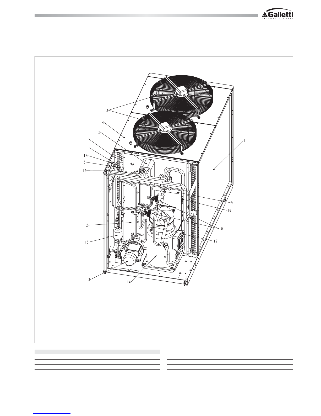
9
MPE 28 ÷ 40
All copying, even partial, of this manual is strictly forbiddenRG66007169 - Rev 00
1 THE MPE SERIES
1.3 COMPONENTS LAY-OUT
DESCRIPTION
1. R410A-air heat-exchanger
2. R410A-water heat-exchanger
3. Fans
4. Water differential pressure switch (fan housing)
5. Automatic air purge valve
6. Expansion vessel (fan housing)
7. Water tank (accessory)
9. 4-way valve (MPE H)
10. Thermostatic valve
11. Water safety valve
12. Liquid receiver (fan housing)
13. Pump
14. Compressor
15. Refrigerant filter
16. Low pressure switch and charge port
17. High pressure switch and charge port
18. Water gauge
19. Water charge
Page 10
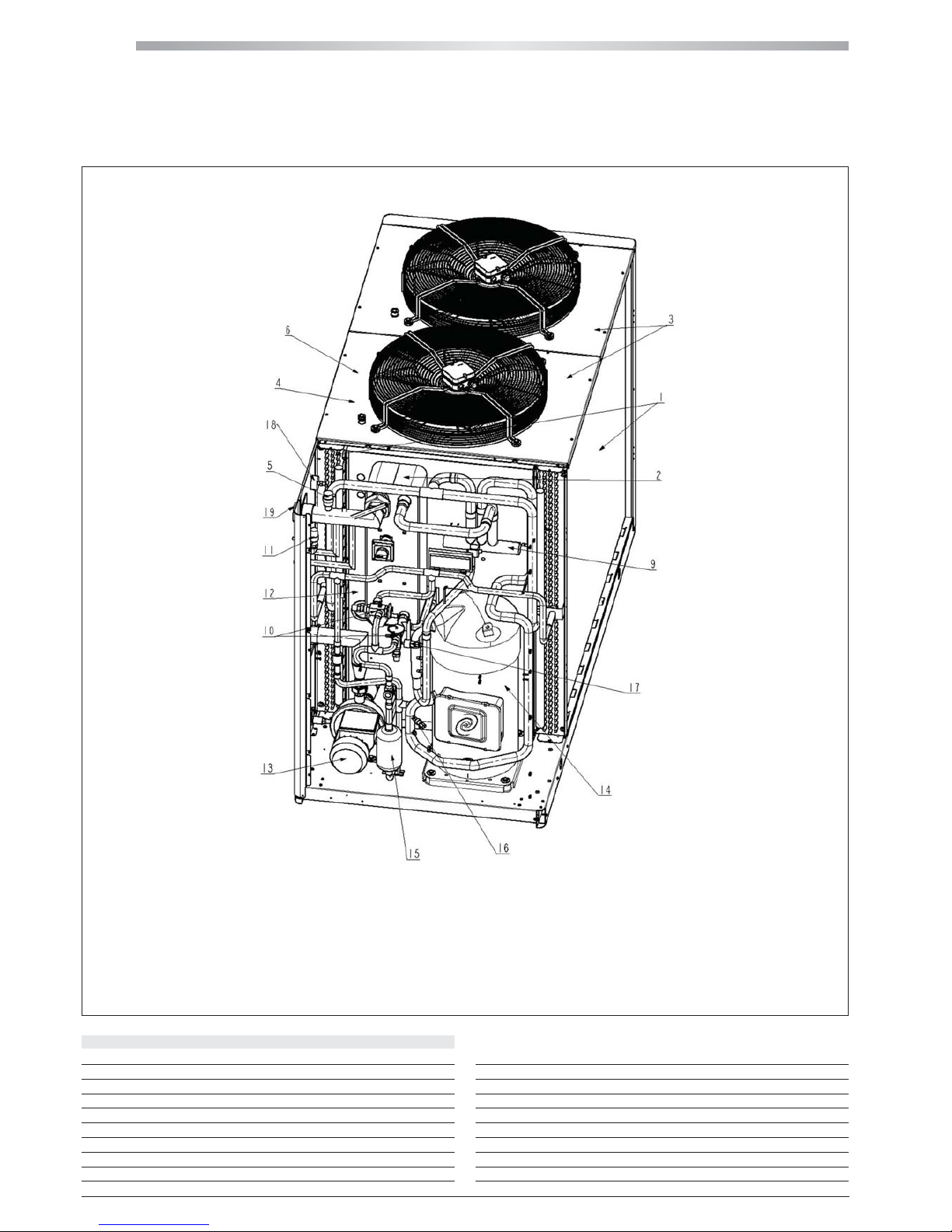
MPE
10
MPE 54 ÷ 66
All copying, even partial, of this manual is strictly forbidden RG66007169 - Rev 00
1 THE MPE SERIES
1.3 COMPONENTS LAY-OUT
DESCRIPTION
1. R410A-air heat-exchanger
2. R410A-water heat-exchanger
3. Fans
4. Water differential pressure switch (fan housing)
5. Automatic air purge valve
6. Expansion vessel (fan housing)
7. Water tank (accessory)
9. 4-way valve (MPE H)
10. Thermostatic valve
11. Water safety valve
12. Liquid receiver (fan housing)
13. Pump
14. Compressor
15. Refrigerant filter
16. Low pressure switch and charge port
17. High pressure switch and charge port
18. Water gauge
19. Water charge
Page 11
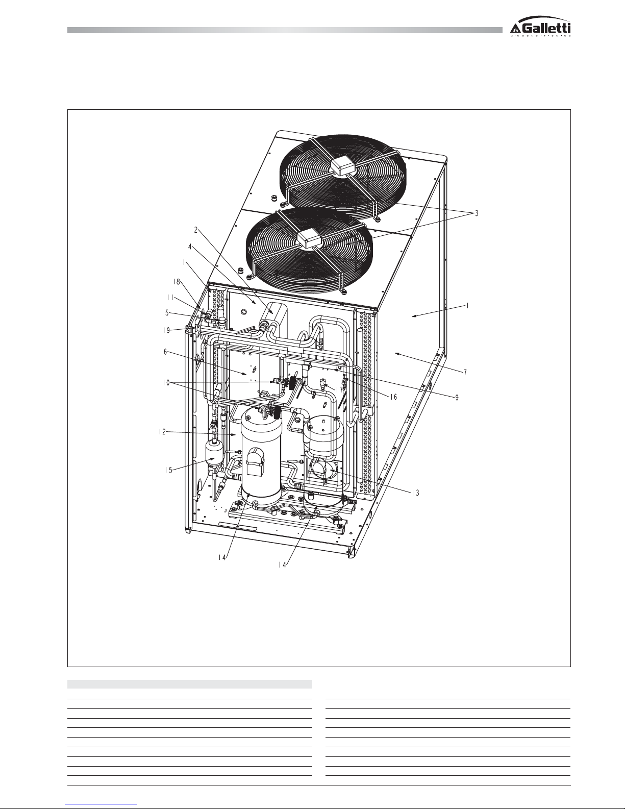
11
MPE 30 ÷ 45 T
All copying, even partial, of this manual is strictly forbiddenRG66007169 - Rev 00
1 THE MPE SERIES
1.3 COMPONENTS LAY-OUT
DESCRIPTION
1. R410A-air heat-exchanger
2. R410A-water heat-exchanger
3. Fans
4. Water differential pressure switch (fan housing)
5. Automatic air purge valve
6. Expansion vessel (fan housing)
7. Water tank (accessory)
9. 4-way valve (MPE H)
10. Thermostatic valve
11. Water safety valve
12. Liquid receiver (fan housing)
13. Pump
14. Compressor
15. Refrigerant filter
16. Low pressure switch and charge port
17. High pressure switch and charge port
18. Water gauge
19. Water charge
Page 12
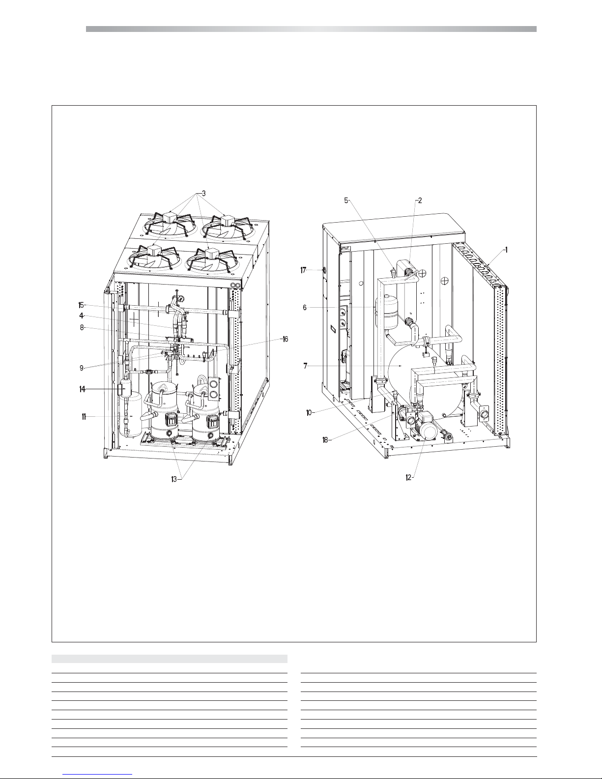
MPE
12
MPE 54 ÷ 76T
All copying, even partial, of this manual is strictly forbidden RG66007169 - Rev 00
1 THE MPE SERIES
1.3 COMPONENTS LAY-OUT
DESCRIPTION
1. R410A-air heat-exchanger
2. R410A-water heat-exchanger
3. Fans
4. Water differential pressure switch (fan housing)
5. Automatic air purge valve
6. Expansion vessel (fan housing)
7. Water tank (accessory)
8. 4-way valve (MPE H)
9. Thermostatic valve
10. Water safety valve
11. Liquid receiver (fan housing)
12. Pump
13. Compressor
14. Refrigerant filter
15. Low pressure switch and charge port
16. High pressure switch and charge port
17. Water gauge
18. Water charge
Page 13
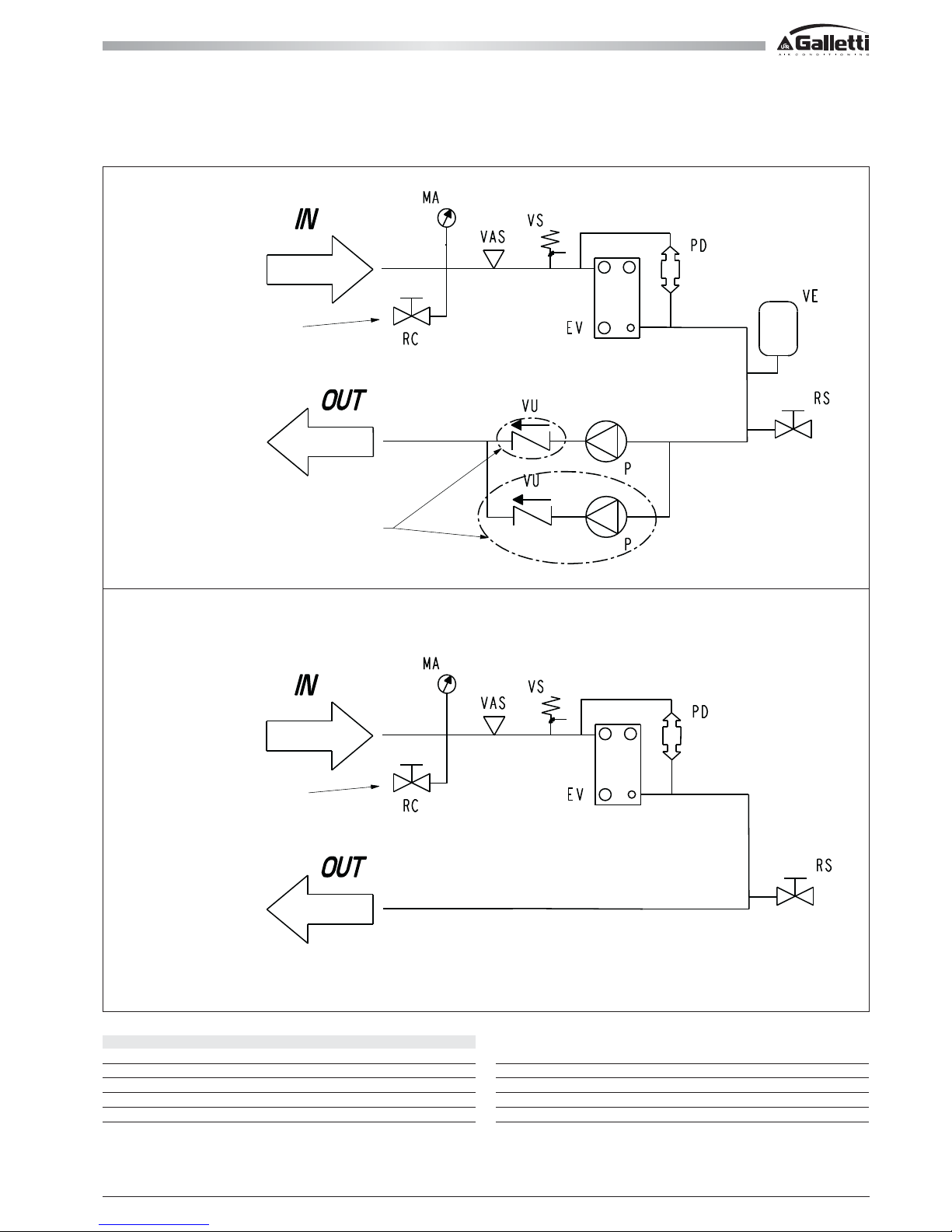
13
All copying, even partial, of this manual is strictly forbiddenRG66007169 - Rev 00
1 THE MPE SERIES
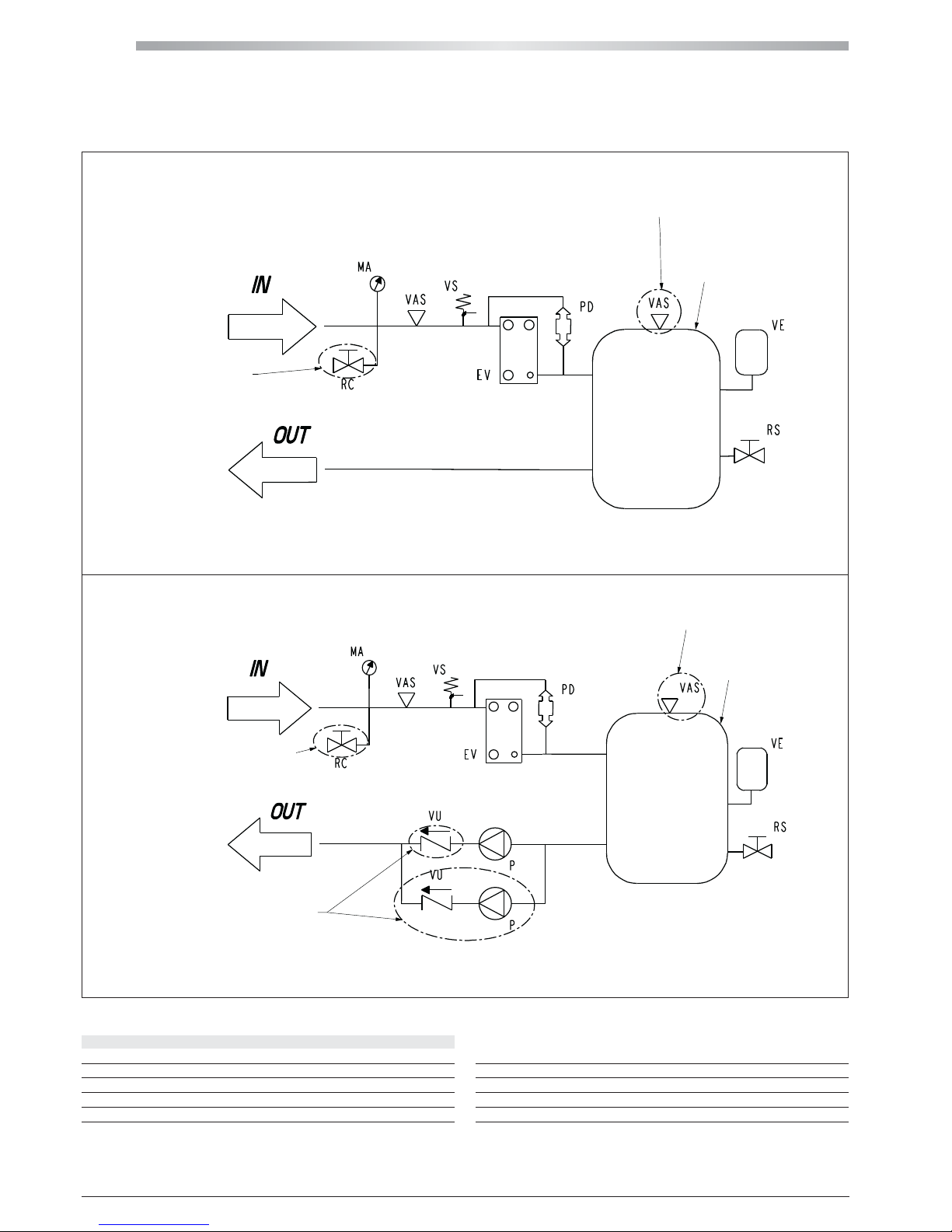
1.4 WATER CIRCUITS
MPE (EVAPORATOR AND PUMP)MPE (EVAPORATOR)
OPTIONAL
OPTIONAL
LEGEND
VS Safety valve
EV Evaporator
PD Water differential pressure switch
MA Water gauge
VAS Air bleed hole
OPTIONAL ONLY FOR MPE
28-66 / 30-45T / 54-76T RANGE
VE Expansion vessel
P Pump
RS Drain
RC Water charge
VU Check valve
Page 14
MPE
14
All copying, even partial, of this manual is strictly forbidden RG66007169 - Rev 00
1 THE MPE SERIES
1.4 WATER CIRCUITS
MPE (EVAPORATOR AND BUFFER TANK)MPE (EVAPORATOR, PUMP AND BUFFER TANK)
OPTIONAL
OPTIONAL
OPTIONAL ONLY FOR MPE
28-66 / 30-45T / 54-76T RANGE
ONLY FOR MPE 10-27 RANGE
ONLY FOR MPE 10-27 RANGE
NOT AVAILABLE FOR
MPE 04-08
NOT AVAILABLE FOR
MPE 04-08
LEGEND
VS Safety valve
EV Evaporator
PD Water differential pressure switch
MA Water gauge
VAS Air bleed hole
VE Expansion vessel
P Pump
RS Drain
RC Water charge
VU Check valve
Page 15
15
All copying, even partial, of this manual is strictly forbiddenRG66007169 - Rev 00
2 INSPECTION, CONVEYANCE DIMENSIONAL AND SITING
2.1 INSPECTION
On receiving the unit, check that the packing is intact: the machine left the factory in per fect conditions and after thorough inspection.
Should you detect any signs of damage, immediately report them to the carrier and note them on the delivery slip.
Galletti S.p.A. must be notified of the entity of the damage within 8 days of the delivery date.
Check that the following items are present:
- starting up module,
- wiring diagram,
- warranty certificate
- make sure that this manual is intact (56 pages)
2.2 CONVEYANCE
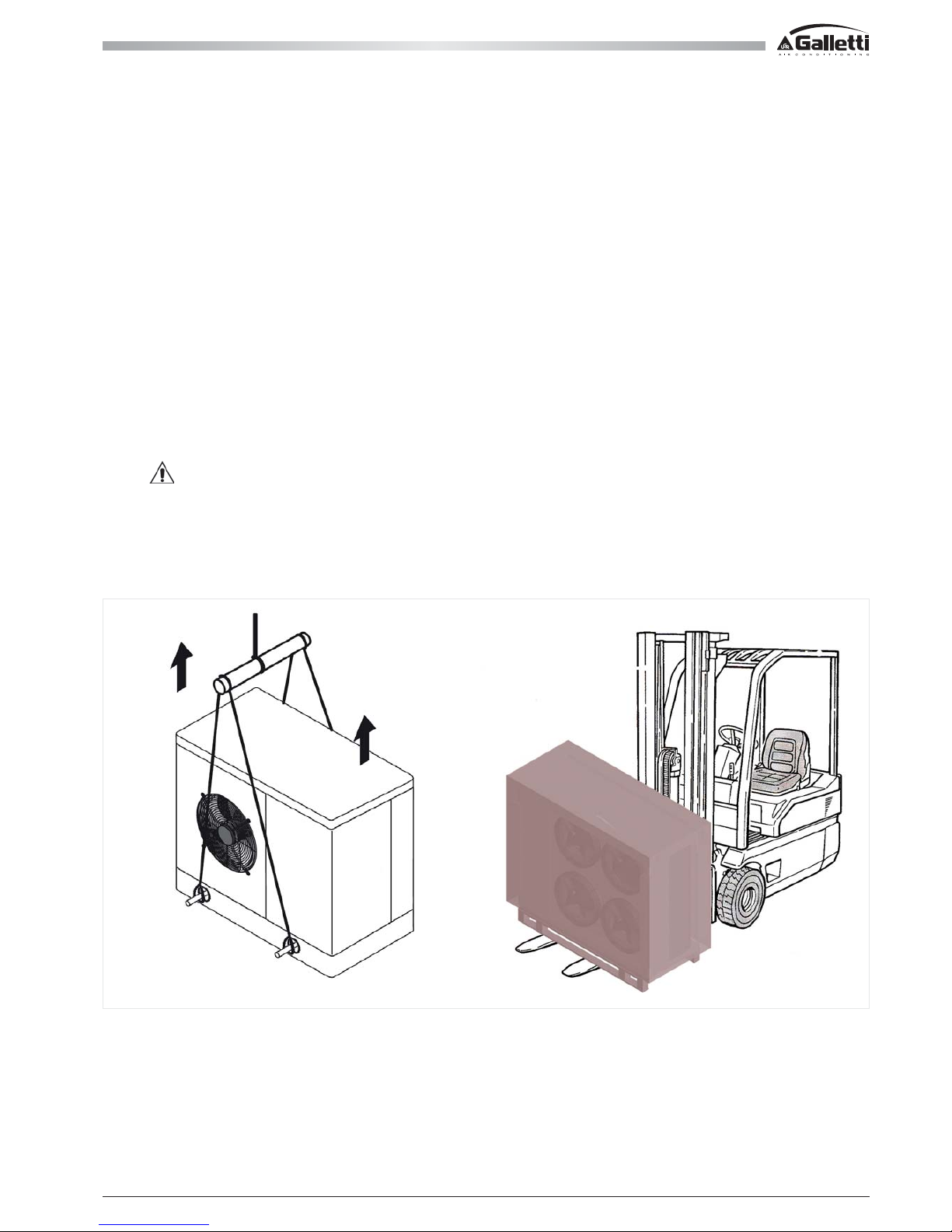
During handling it is compulsory to check dimensions, weights, centre of gravity and anchorages. Check as well that lifting and positioning devices conform
to the current safety regulations. The unit leaves the factory screwed onto a wooden pallet, which allows it to be easily conveyed with a forklift truck.
After removing the unit from the pallet, handle it gently, without applying excessive pressure on the side panels, finned coil and fan grille. You should collect
and separate the packing materials (wood, cardboard, nylon etc.) and make them available for recycling in order to minimise their environmental impact.
Before lifting, remove the screws that fasten the machine base to the wooden pallet. The unit must be lifted using Ø 1½” GAS steel pipes at least 3mm
thick, to be inserted in the round holes on the base side members (see figure) and identified by means of stickers. Piping must protrude of at least 250-300
mm from each side, be slung with ropes of equal length and secured to the lifting hook (provide stops at the ends of the pipes to prevent the ropes from
slipping off due to the weight). Use ropes and belts sufficiently long to extend beyond the height of the machine and place spacer bars and boards on the
top to prevent damaging the sides and the top of the unit. In this phase, before the definitive position, vibration damping supports can be installed (optional).
Warning
In all lifting operations make sure that the unit is securely anchored in order to prevent accidental falls or overturning.
Page 16
MPE
16
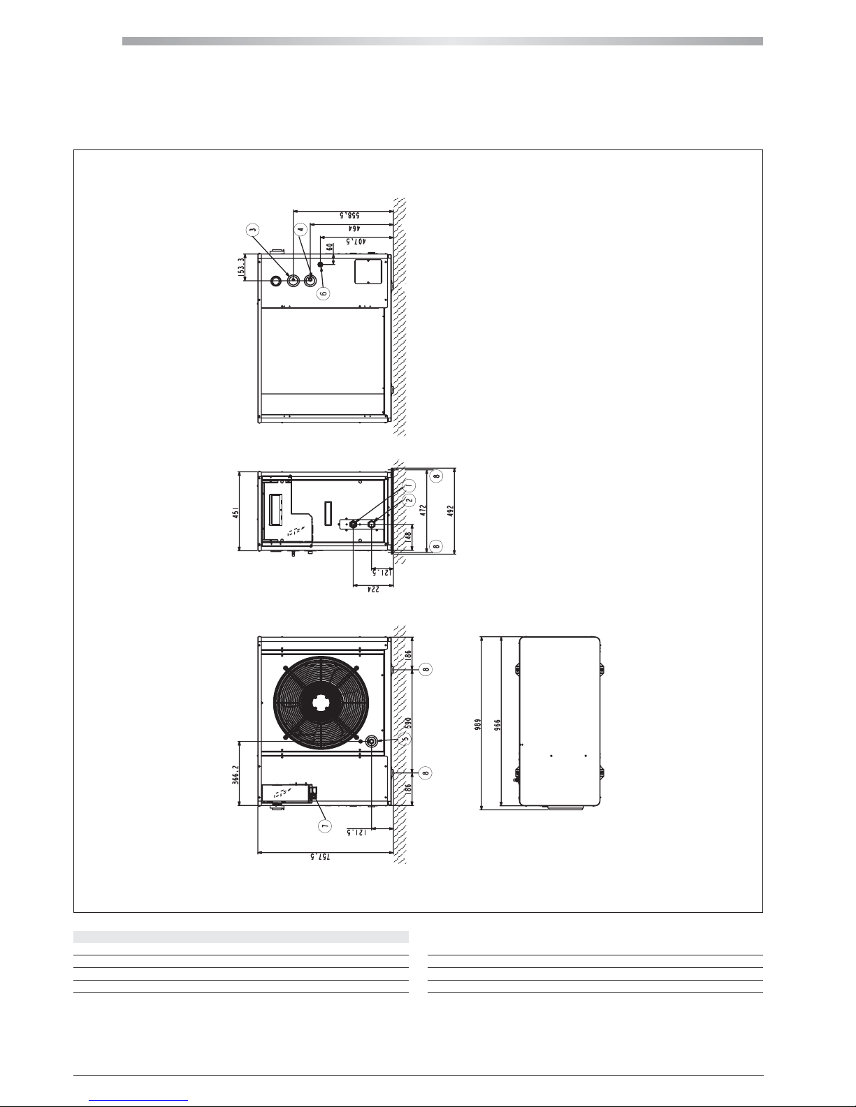
MPE 04 ÷ 08
All copying, even partial, of this manual is strictly forbidden RG66007169 - Rev 00
2 INSPECTION, CONVEYANCE DIMENSIONAL AND SITING
2.3 DIMENSIONAL
LEGEND
1. Water in 1" female
2. Water out 1" female
3. Safety valve discharge outlet provided with rubber ring holder
4. Water supply
1
/2" male (optional tap)
5. Drain manifold 1/2" female
6. Power supply Ø 28 mm
7. Electric control board
8. Dampers fastening points (accessory)
Page 17
17
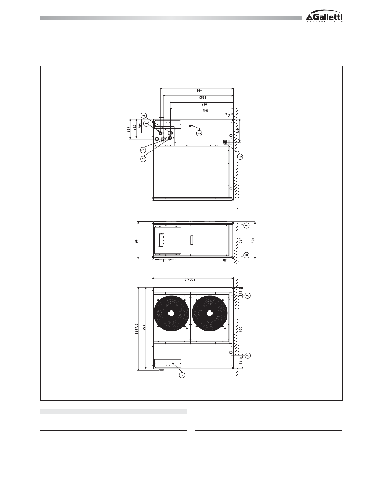
MPE 10 ÷ 15
All copying, even partial, of this manual is strictly forbiddenRG66007169 - Rev 00
2 INSPECTION, CONVEYANCE DIMENSIONAL AND SITING
2.3 DIMENSIONAL
LEGEND
1. Water in 1"
1
/4 female
2. Water out 1"
1
/4 female
3. Safety valve discharge outlet provided with rubber ring holder
4. Water supply
1
/2" male (optional tap)
5. Drain manifold 1/2" female
6. Power supply Ø 28 mm
7. Electric control board
8. Dampers fastening points (accessory)
Page 18
MPE
18
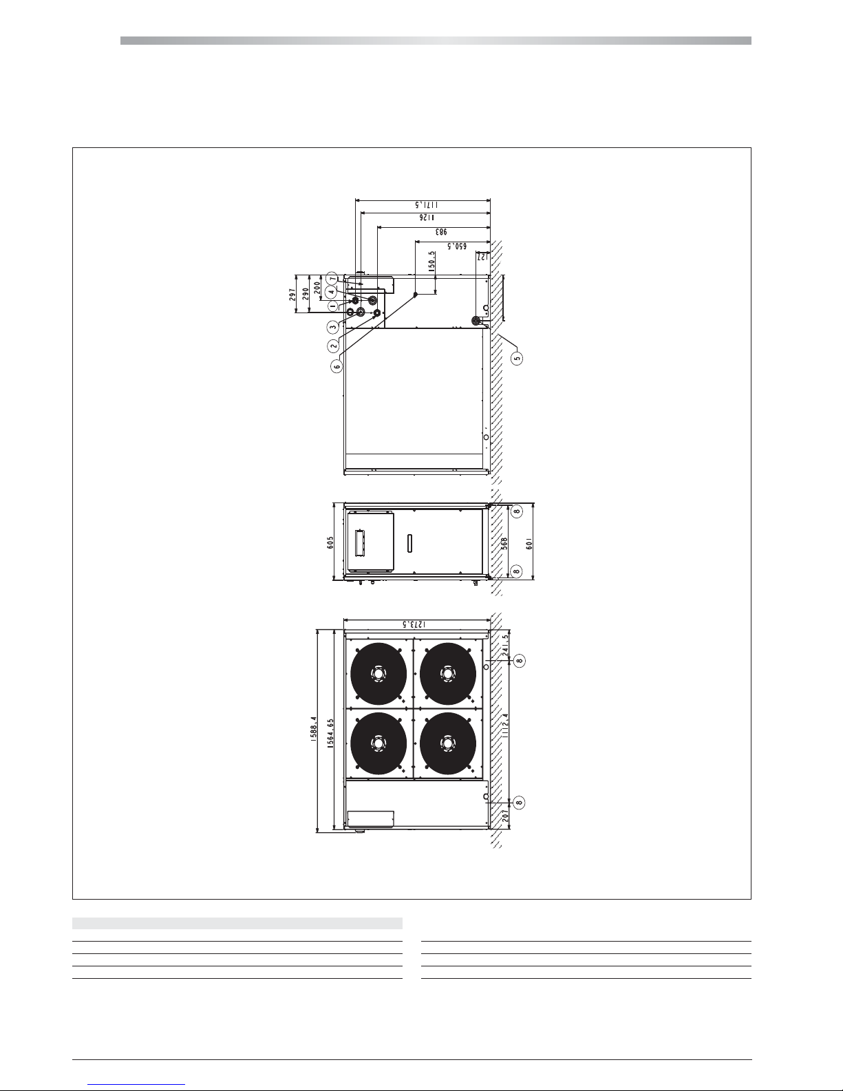
MPE 18 ÷ 27
All copying, even partial, of this manual is strictly forbidden RG66007169 - Rev 00
2 INSPECTION, CONVEYANCE DIMENSIONAL AND SITING
2.3 DIMENSIONAL
LEGEND
1. Water in 1"
1
/4 female
2. Water out 1"
1
/4 female
3. Safety valve discharge outlet provided with rubber ring holder
4. Water supply
1
/2" male (optional tap)
5. Drain manifold 1/2" female
6. Power supply ĭ 28 mm
7. Electric control board
8. Dampers fastening points (accessory)
Page 19
19
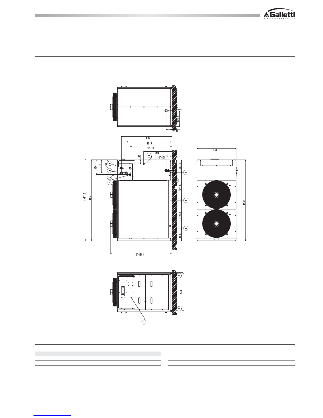
MPE 28 ÷ 40 - MPE 30 ÷ 45 T
All copying, even partial, of this manual is strictly forbiddenRG66007169 - Rev 00
2 INSPECTION, CONVEYANCE DIMENSIONAL AND SITING
2.3 DIMENSIONAL
MPE 28-45 WITH BUFFER TANK
MPE 30-45 T
LEGEND
1. Water in 1"
1
/4 female
2. Water out 1"
1
/4 female
3. Safety valve discharge outlet provided with rubber ring holder
4. Water supply
1
/2" male (optional tap)
5. Drain manifold 1/2" female
6. Power supply Ø 37 mm
7. Electric control board
8. Dampers fastening points (accessory)
Page 20
MPE
20
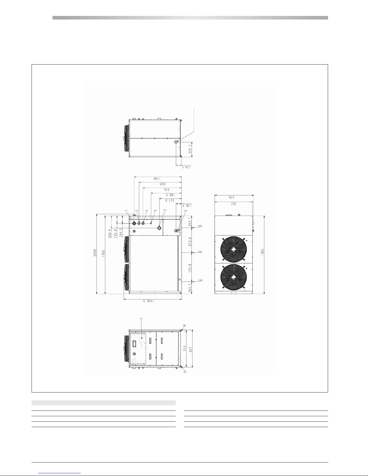
MPE 54 ÷ 66
All copying, even partial, of this manual is strictly forbidden RG66007169 - Rev 00
2 INSPECTION, CONVEYANCE DIMENSIONAL AND SITING
2.3 DIMENSIONAL
MPE 54-66 WITH BUFFER TANK
LEGEND
1. Water in 2" female
2. Water out 2" female
3. Safety valve discharge outlet provided with rubber ring holder
4. Water supply
1
/2" male (optional tap)
5. Drain manifold 1/2" female
6. Power supply Ø 37 mm
7. Electric control board
8. Dampers fastening points (accessory)
Page 21
21
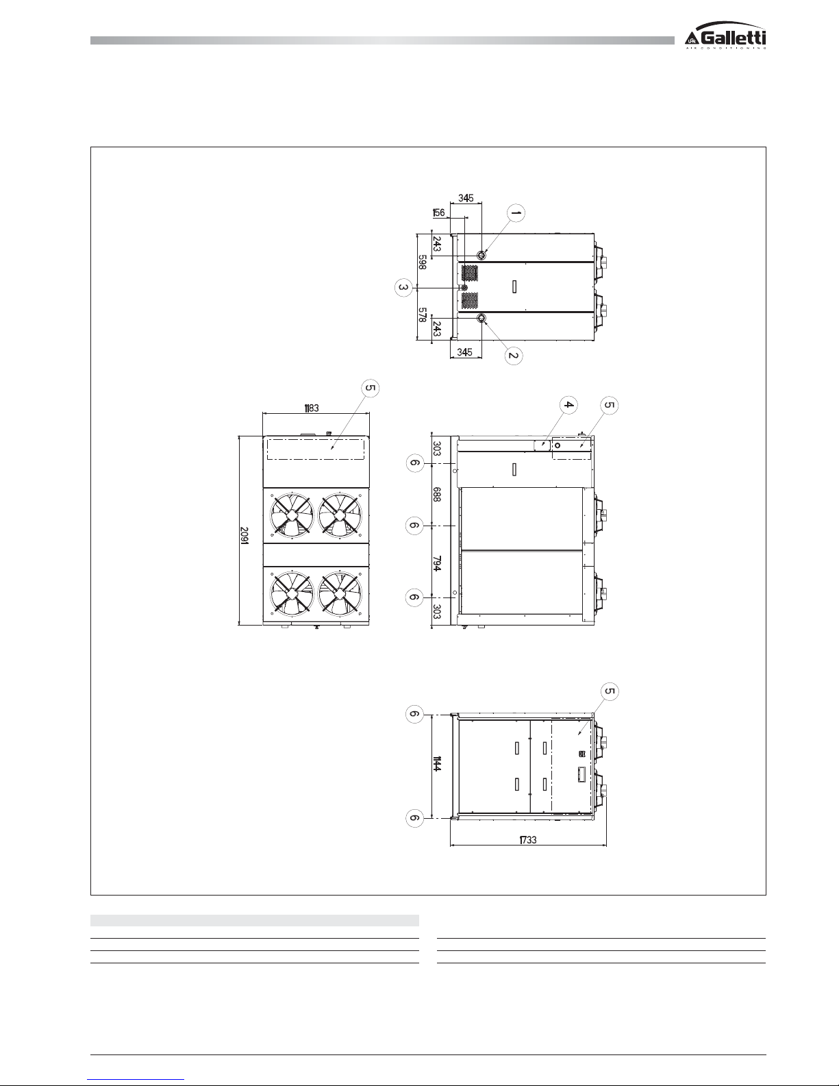
MPE 54 ÷ 76T
All copying, even partial, of this manual is strictly forbiddenRG66007169 - Rev 00
2 INSPECTION, CONVEYANCE DIMENSIONAL AND SITING
2.3 DIMENSIONAL
LEGEND
1. Water in 2" female
2. Water out 2" female
3. Drain manifold
1
/2" female
4. Power supply
5. Electric control board
6. Dampers fastening points (accessory)
Page 22
MPE
22
MPE 04 ÷ 08
1
All copying, even partial, of this manual is strictly forbidden RG66007169 - Rev 00
2 INSPECTION, CONVEYANCE DIMENSIONAL AND SITING
2.4 SITING
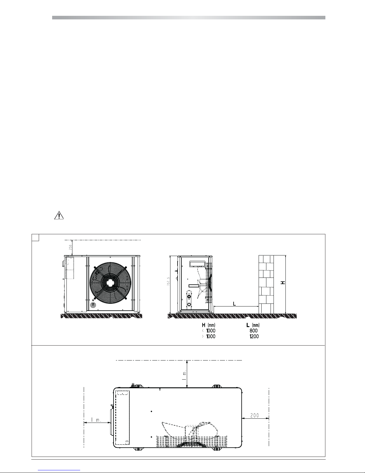
It is important to bear in mind the following aspects when choosing the best site for installing the unit:
- size and origin of water pipes;
- location of the power supply;
- solidity of the supporting surface;
- avoid obstacles to the outflow of air from the fan which could cause back suction (see section on "installation clearance requirements");
- Direction of prevalent winds: (position the unit so as to prevent prevalent winds from interfering with the fan air flow)
Prevalent winds opposing the fan air flow will result in a maximum air temperature below the value indicated in the operating limits;
Wind flowing in the same direction as the fan flow will result in a minimum air temperature above the value indicated in the operating limits.
Even when the chiller is running in the heat pump mode, wind may have the effect of reducing the range of operation"
- avoid the possible reverberation of sound waves; do not install the unit in narrow or cramped spaces;
- ensure adequate accessibility for maintenance or repairs (see section on "installation clearance requirements").
This appliance is not intended to be used by children or persons with physical, sensorial or mental problems, inexpert or unprepared, without
supervision. Be careful that children do not approach the appliance.
2.4.1 INSTALLATION CLEARANCE REQUIREMENTS
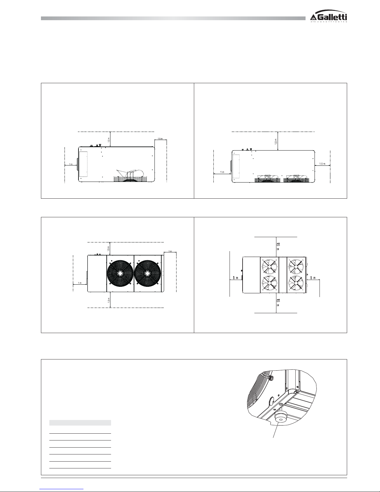
To guarantee the proper functioning of the unit and access for maintenance purposes, it is necessary to comply with the minimum installation clearance
requirements shown in figures 1, 2 and 3.
Verify that there are no obstacoles in front of the fans air outlet.
Avoid any and all situations of backflow of hot air between air outlet and inlet of the unit.
If even only one of the above conditions is not fulfilled, please contact the manufacturer to check for feasibility.
In the design of the MPE series, special care has been taken to minimise noise and vibrations transmitted to the ground.
Even greater insulation may be obtained, however, by using vibration damping base supports (available as optional accessories).
If vibration damping base supports are adopted, it is strongly recommended also to use vibration damping couplings on the water pipes.
Whenever the unit is to be sited on unstable ground (various types of soil, gardens, etc.) it is a good idea to provide a supporting base of adequate dimensions.
Warning
heat pump units produce condensation while operating in the heating mode.
HEAT EXCHANGER WATER CONNECTION SIDE
EXCHANGER SIDE
ELECTRICAL BOX
Page 23
23
All copying, even partial, of this manual is strictly forbiddenRG66007169 - Rev 00
2 INSPECTION, CONVEYANCE DIMENSIONAL AND SITING
2.4 SITING
2.4.1 INSTALLATION CLEARANCE REQUIREMENTS
HEAT EXCHANGER WATER CONNECTION SIDE
ELECTRICAL BOX
EXCHANGER SIDE
HEAT EXCHANGER WATER CONNECTION SIDE
EXCHANGER SIDE
ELECTRICAL BOX
MPE N° DAMPERS
04 - 08 4
10 - 15 4
18 - 27 4
28 - 66 6
30 - 45 T 6
54 - 76 T 6
2.5 DAMPERS SITING
DAMPERS
MPE 30-45T SIDE DISCHARGE WATER
ELECTRICAL BOX
EXCHANGER SIDE
HEAT EXCHANGER WATER CONNECTION SIDE
MPE 30-45T SIDE DISCHARGE WATER
HEAT EXCHANGER WATER CONNECTION SIDE
ELECTRICAL BOX
EXCHANGER SIDE
Page 24
MPE
24
All copying, even partial, of this manual is strictly forbidden RG66007169 - Rev 00
3 PLUMBING AND ELECTRICAL CONNECTIONS
3.1 PLUMBING CONNECTION
All the units belonging to the MPE series are equipped with water differential pressure switch, safety valve, water pressure gauge and automatic filling device
and emptying tap.
Furthermore, depending on the version, MPE units can be supplied complete with pump, expansion vessel and buffer tank:
3.1.1 HYDRAULIC CONNECTION
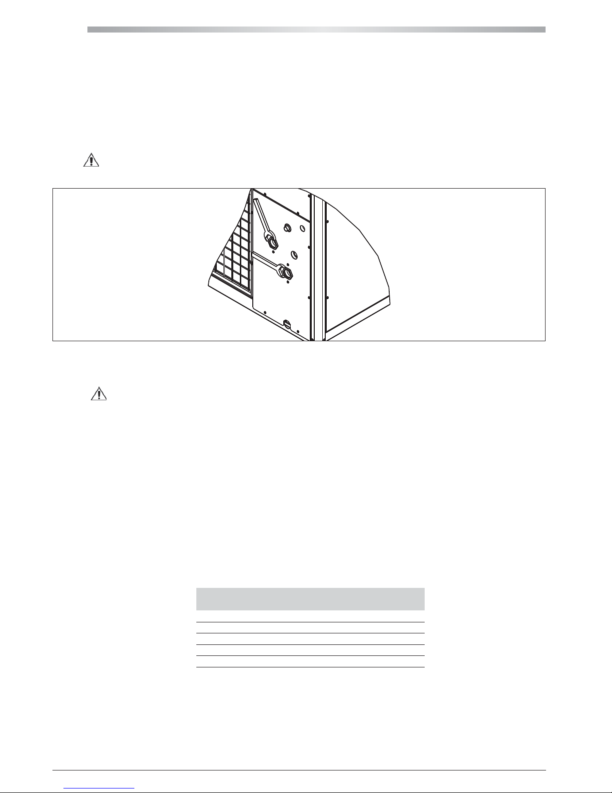
Warning
While connecting the taps, hold the unit's plumbing connections tightly in place using a hexagonal wrench to prevent the pipes inside the
unit from being damaged (see figure).
3.1.2 RECOMMENDED WATER CIRCUIT
Warning
when making the plumbing connections, make sure there are no open flames in proximity to or inside the unit.
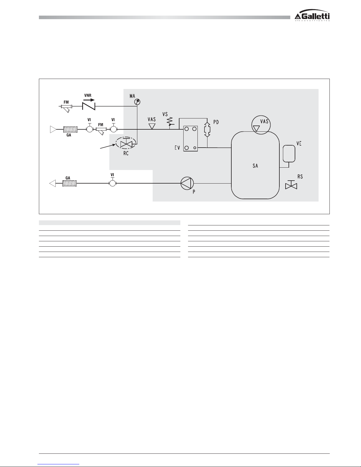
When setting up the water circuit, it is advisable to equip it with:
- valves for regulating (VI) the unit on the water pipes, immediately upstream and downstream from the unit itself, to be used in the event maintenance
work is required;
- standard mechanical filter (FM) (OBLIGATORY!) on the pipe feeding the unit, in proximity to the latter;
- standard mechanical filter (FM) (OBLIGATORY!) and check valve (VNR), on the supply line upstream from the filling tap (RC);
- an air vent valve at the highest point of the circuit;
- escape pipe for the safety valve (VS), which, in the event the safety valve opens, diverts the jet of water to an area where it cannot harm persons or
damage property (Important!);
- vibration-damping couplings (GA) on the pipes to prevent vibrations from being transmitted toward the system.
Important! It is advisable to ensure that the pipes connected upstream and downstream from the unit are not smaller in diameter than the plumbing
connections of the unit itself.
Important! During wintertime the water circuit (or the water chiller only) must be emptied to prevent damage caused by freezing; alternatively, the
circuit may be filled with a mixture of water and glycol; the percentage of glycol necessary will depend on the lowest forecast temperature (see table):
Percentage by weight Mixture freezing
of ethylene glycol (%) temperature (°C)
0 0
10 -4
15 -8
20 -14
30 -18
Important! If different antifreeze product is to be used, please contact the manufacturer.
Failure to install filters and vibration dampers may cause problems of clogging, breakages and noise, for which the manufacturer may not be held liable.
Page 25
25
All copying, even partial, of this manual is strictly forbiddenRG66007169 - Rev 00
3 PLUMBING AND ELECTRICAL CONNECTIONS
3.1 PLUMBING CONNECTION
3.1.2 RECOMMENDED WATER CIRCUIT
3.1.3 FILLING THE SYSTEM
- Before you start filling, make sure that the system drainage cock is closed.
- Open all the air vent valves of the system and of the indoor units and chiller.
- Open the system regulating devices.
- To fill the circuit open slowly the water tap of the system (optional).
- When water starts coming out of the air vent valves of the indoor units, close them and continue filling until the pressure gauge reading is 1.5 bars.
OPTIONAL
LEGEND
VS Safety valve
EV Evaporator
PD Water differential pressure switch
MA Water gauge
VAS Air bleed hole
SA Storage tank
VE Expansion vessel
RS Drain
RC Water charge
VI Regulation valve (not supplied)
GA Vibration-damping coupling (not supplied)
FM Mechanical filter (OBLIGATORY)
VNR Check valve (not supplied)
Page 26
MPE
26
4 5
All copying, even partial, of this manual is strictly forbidden RG66007169 - Rev 00
3 PLUMBING AND ELECTRICAL CONNECTIONS
3.2 ELECTRICAL CONNECTIONS
All operations must be performed by qualified service personnel in accordance with current laws and regulations. For any electrical work on the unit, refer
to the electric diagrams supplied with the unit.
It is recommended to make sure that:
- The characteristics of the mains power supply are adequate for the electrical inputs specified in the table of electrical data.
Warning Before carrying out any job on electrical parts, make sure the power supply is disconnected. Check that the mains electricity supply
is compatible with the specifications (voltage, number of phases, frequency) shown on the unit rating plate. The supply voltage may not undergo
fluctuations exceeding ±5% of the rated voltage. The electrical connections must be made in accordance with the wiring diagram provided with the
unit and the regulations in force.
Warning
Never attempt to modify internal electrical connections: any undue modifications will immediately invalidate the warranty.
Important! An all-pole circuit breaker must be used on the electric panel upstream, conform to IEC Standards (contacts must be open at least of 3
mm), with suitable interruption capacity and differential protection, according to the electrical data table described below, and installed as close as
possible to the device. For the machine power supply line, use H07RN-F rubber flexible cables, with section as indicated in the table. For the cable
passage, use sheaths and channels suitable for outdoor installation. Provide a line switch and delayed-type fuses with features as indicated in the table.
Important! Upstream from the electric control board, you must provide a switch with a delayed fuse meeting the specifications indicated in the table
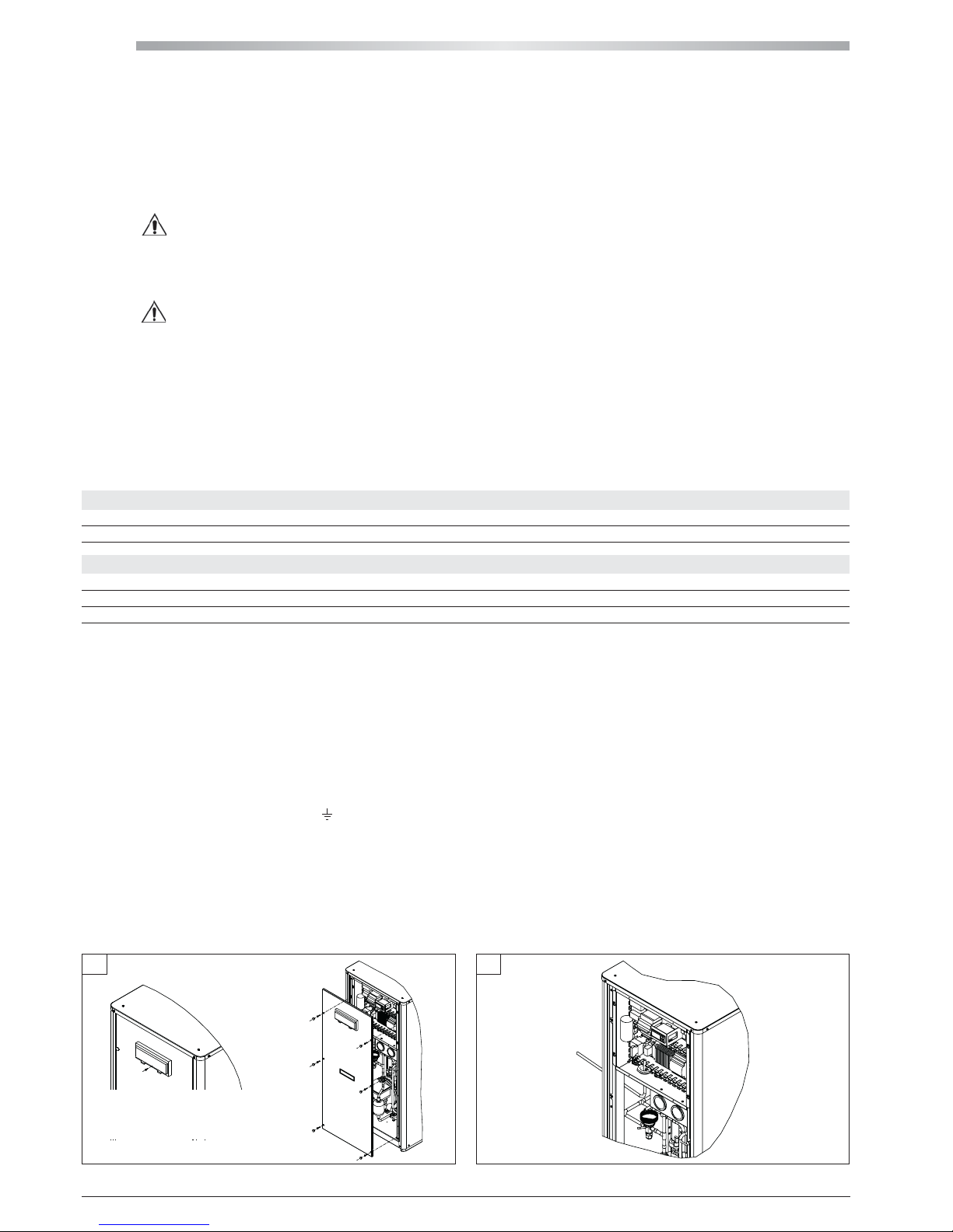
To access the electric control board it is necessary to remove the inspection panel (figure 4) by taking out the screws; introduce the power cable into
the unit through the bushing on the side panel; then bring it to the electric control board through the cable holder provided.
Important! Tighten the wires securely to the terminals and clamp the cable in place with the cable holder (figure 5).
Important! Make sure that the length of cable inside the unit enters the bushing from below: this is necessary to prevent rainwater from dripping inside
the unit.
Important! To preserve the protection degree of the machine, use a cable gland compatible with the sheath or power cable diameter, in correspondence
to the unit side panel hole.
Important! An earth connection is mandatory: connect the earthing wire to the terminal provided on the electric control board (see the electric control
board layout supplied with the unit ), marked
.
Important! If you wish to include:
- a remote on/off switch
- a remote switch for changing over between the cooling and heating mode (MPE H only),
- a remote alarm indicator
it is a good idea to do so at this stage of the installation procedure, by connecting the switches or PCDS remote control (accessory) to the electric
control board terminals as directed in section 3.3 and using the unit wiring diagram as your reference.
MPE 004M 005M 007M 008 M 008 010 M 010 013 015 018 020 024 027 028
Power cables mm
2
4 4 6 6 4 6 4 4 4 6 6 10 10 10
Safety fuse F A 16 16 20 25 10 32 16 20 20 25 25 32 32 32
Circuit breaker IL A 20 20 25 25 16 32 20 25 25 25 25 32 32 32
MPE 032 035 040 054 066 T30 T34 T40 T45 T54 T61 T69 T76
Power cables mm
2
10 10 10 16 16 10 16 16 16 16 16 16 25
Safety fuse F A 32 40 40 50 50 40 50 63 63 63 63 63 80
Circuit breaker IL A 40 40 50 63 63 50 50 63 63 63 63 63 80
Page 27
27
All copying, even partial, of this manual is strictly forbiddenRG66007169 - Rev 00
- The maximum input power is the mains power that must be available in order for the unit to work.
- The maximum current absorption refers to the current that will trigger the internal safety devices of the unit. It is the maximum current allowed in the unit
This value may never be exceeded; it must be used as a reference for determining the size of the power supply line and the related safety devices
(refer to the wiring diagram supplied with the units). Cross-section area of cables: 4 A/mm2 approx.
3 PLUMBING AND ELECTRICAL CONNECTIONS
3.3 ELECTRICAL DATA
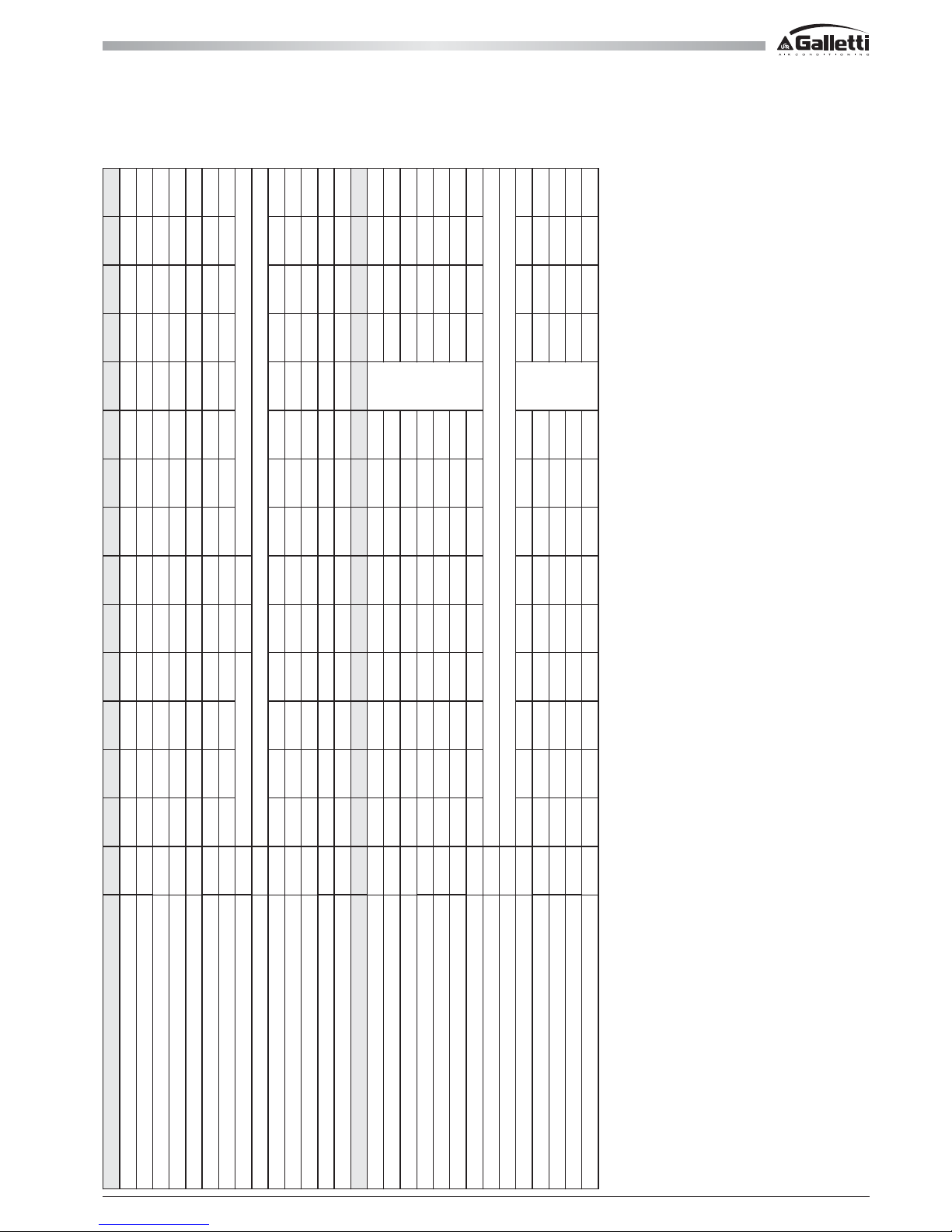
MPE 004M 005M 007M 008 M 008 010 M 010 013 015 018 020 024 027 028
Maximum power input kW 2,0 2,3 3,0 5,0 5,0 5,1 7,2 8,9 10,5 12,5 13,6 14,5 18,0 18,3
Maximum current absorption A 9,8 11,6 15,3 24,2 9,2 26,3 12,3 15,4 18,0 21,7 21,7 24,0 28,6 28,6
Starting absorbed current A 38 44 63 98 49 99 50 65 68 75 104 158 132 133
Fan motor rated power kW 0,135 0,135 0,135 0,135 0,135 0,135 0,135 0,135 0,135 0,135 0,135 0,135 0,135 0,320
Fan motor rated current A 0,64 0,64 0,64 0,64 0,64 0,64 0,64 0,64 0,64 0,64 0,64 0,64 0,64 1,75
Pump motor rated power kW 0,14 0,14 0,14 0,14 0,14 0,37 0,37 0,37 0,37 0,37 0,37 0,37 0,37 0,55
Pump motor rated current A 0,58 0,58 0,58 0,58 0,58 2,00 2,00 2,00 2,00 2,00 2,00 2,00 2,00 3,00
Power supply V/f/Hz
Auxiliary power supply V/f/Hz
Power cables mm2 4,0 4,0 6,0 6,0 4,0 6,0 4,0 4,0 4,0 6,0 6,0 10,0 10,0 10,0
PCD connecting cables mm2
PCDS connecting cables mm2 1,0 1,0 1,0 1,0 1,0 1,0 1,0 1,0 1,0 1,0 1,0 1,0 1,0 1,0
Safety fuse F A 16,0 16,0 20,0 25,0 10,0 32,0 16,0 20,0 20,0 25,0 25,0 32,0 32,0 32,0
Circuit breaker IL A 20,0 20,0 25,0 25,0 16,0 32,0 20,0 25,0 25,0 25,0 25,0 32,0 32,0 32,0
MPE 032 035 040 054 066 T30 T34 T40 T45 T54 T61 T69 T76
Maximum power input kW 18,9 21,8 22,4 22,7 23,3 20,9 24,4 26,6 30,8 27,0 30,0 32,0 39,0
Maximum current absorption A 32,4 35,2 36,4 45,2 46,2 39,9 45,9 49,7 56,7 48,0 53,0 57,0 69,0
Starting absorbed current A 166 161 163 163 165 86 96 127 130 177 187 202 229
Fan motor rated power kW 0,320 0,320 0,320 0,610 0,610 0,320 0,320 0,320 0,320 0,400 0,400 0,400 0,400
Fan motor rated current A 1,75 1,75 1,75 2,65 2,65 1,75 1,75 1,75 1,75 1,80 1,80 1,80 1,80
Pump motor rated power kW 0,55 0,55 0,55 0,90 0,90 0,55 0,55 0,55 0,55 1,30 1,30 1,30 1,30
Pump motor rated current A 3,00 3,00 3,00 4,90 4,90 3,00 3,00 3,00 3,00 5,90 5,90 5,90 5,90
Power supply V/f/Hz
Auxiliary power supply V/f/Hz
Power cables mm2 10,0 10,0 10,0 16,0 16,0 10,0 16,0 16,0 16,0 16,0 16,0 16,0 25,0
PCD connecting cables mm2
PCDS connecting cables mm2 1,0 1,0 1,0 1,0 1,0 1,0 1,0 1,0 1,0 1,0 1,0 1,0 1,0
Safety fuse F A 32,0 40,0 40,0 50,0 50,0 40,0 50,0 63,0 63,0 63,0 63,0 63,0 80,0
Circuit breaker IL A 40,0 40,0 50,0 63,0 63,0 50,0 50,0 63,0 63,0 63,0 63,0 63,0 80,0
Page 28
MPE
28
R
-IL
-IL
-FL
L1
L1L2
T1T2
L1
L2
L3
N
L2L3N
-FL
-IG
135
N
246
N
400
230
LNPE
L
N
PE
150
3+N 50
STNP
PE
E
-IG
All copying, even partial, of this manual is strictly forbidden RG66007169 - Rev 00
3 PLUMBING AND ELECTRICAL CONNECTIONS
3.3 ELECTRICAL DATA
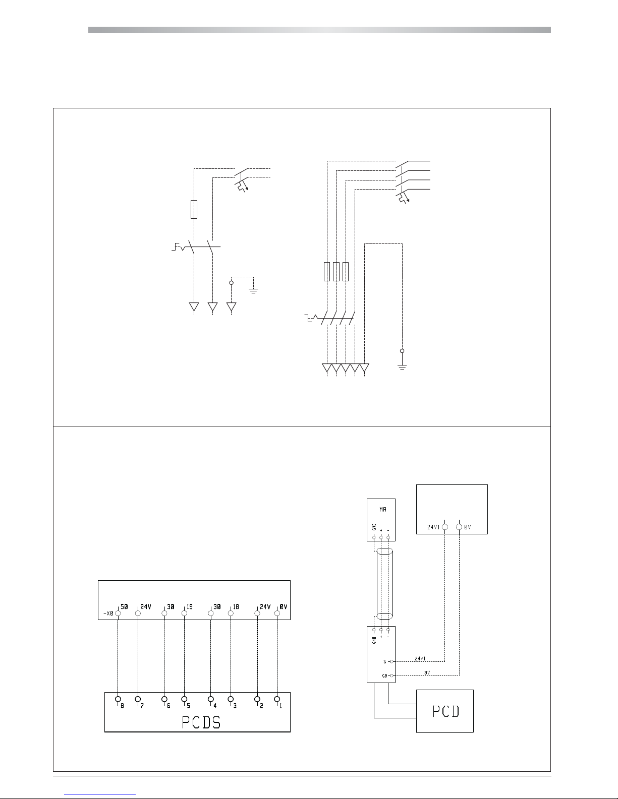
DIAGRAM SHOWING ELECTRICAL CONNECTIONS BETWEEN MPE AND PCDS / PCD REMOTE CONTROL PANEL
NOTE: On the terminal block of the electric control panel a voltage of 24V will be present at the 50/24V terminals in the event of an alarm; if it is desired to inter face with
a voltage-free contact, a relay must be applied for this purpose by the installer.
GENERAL ALARM SIGNAL
COOLING/HEATING REMOTE SELECTION
ON/OFF (STAND-BY) SWITCH
PCDS POWER SUPPLY
USE SHIELDED CABLE
WITH ONE TWISTED
PCD POWER SUPPLY
ELECTRIC BOARD
TERMINAL
ELECTRIC BOARD TERMINAL
MAIN ELECTRICAL CONNECTION OF THE ONE-PHASE AND THREE-PHASE UNITS
Page 29
29
All copying, even partial, of this manual is strictly forbiddenRG66007169 - Rev 00
4 STARTING UP
THE FIRST START UP MUST BE CARRIED OUT EXCLUSIVELY BY QUALIFIED PERSONNEL AND AUTHORIZED BY GALLETTI SPA (SEE WARRANTY
SHEET ATTACHED).
At first start-up of the installation make sure to comply with current national regulations.
4.1 PRELIMINARY CHECKS
When starting up the unit for the first time or after a seasonal period of quiescence, it is advisable to have the following checks performed by specialised
personnel:
- Check that the electrical connections have been made properly and that all the terminals are securely tightened.
- Check that the external power supply is within +-5 % tolerance from the power supply reported on the unit identification label.
If the power supply is subject to frequent voltage fluctuations, contact Galletti S.p.A. for advice on choosing suitable protections.
- Check for refrigerant leaks, with the aid of a leak detector if necessary.
- Check that the plumbing connections have been properly made according to the indications given on the plates to be found on the unit itself
(water inlet, water outlet etc.).
- Make sure that the pump is not blocked.
- Make sure that the water circuit is duly bled to completely eliminate the presence of air: load the circuit gradually and open the air vent valves,
which the installer should have set in place.
Warning
before starting the unit, make sure all the covering panels are in place and secured with the fastening screws provided. To start the unit,
move the main switch to on. Use the keypad of the electronic control as directed in section 3.3 to select the cooling or heating mode.
Warning
You should not disconnect the unit from the power supply during periods when it is inoperative but only when it is to be taken out of
service for a prolonged period (e.g. at the end of the season). To turn off the unit temporarily follow the directions provided in section 3.3.
Warning
do not cut off power using the main switch:
the latter device serves to disconnect the unit from the electricity supply when there is no passage of current, i.e. when the unit is already turned OFF.
Page 30
MPE
30
All copying, even partial, of this manual is strictly forbidden RG66007169 - Rev 00
5 MICROPROCESSOR CONTROL
5.1 DESCRIPTION OF CONTROL PANEL
The control panel of the unit enables the user to display and set the unit's operating parameters and read the main operating data.
In addition it indicates what mode (cooling or heating) the unit is operating in and signals any alarms that may have been triggered.
Any new settings saved are stored in the card and used the next time the unit is switched on, even following a power failure.
5.1.1 REMOTE CONTROL PANELS (ACCESSORIES)
Installing a PCDS remote control panel enables you to switch the unit on and off and set the operating mode (cooling - heating) from a distance and have a
cumulative alarm indicator (thanks to an alarm signalling relay integrated in the electronic control device).
Installing a PCD remote control panel instead provides remote access to all the electronic control functions installed in the unit.
5.1.2 MAIN FUNCTIONS
- Control over the temperature of water entering the evaporator.
- Management of the defrosting function (MPE H only).
- Control of fan speed (standard feature of MPE H, optional for MPE).
- Complete alarm management.
- Setup for serial line connection for supervisor system/tele-help.
- Setup for connection to a remote terminal that duplicates the functions of the electronic control (PCD remote control panel).
5.1.3 DEVICES CONTROLLED
- compressor
- fans
- cycle reversing valve (MPE H only);
- water circulation pump;
- antifreeze heating element (optional);
- electronic control internal alarm signalling relay (designed to control an indicator or buzzer).
5.2 USING THE CONTROL PANEL
5.2.1 DISPLAY
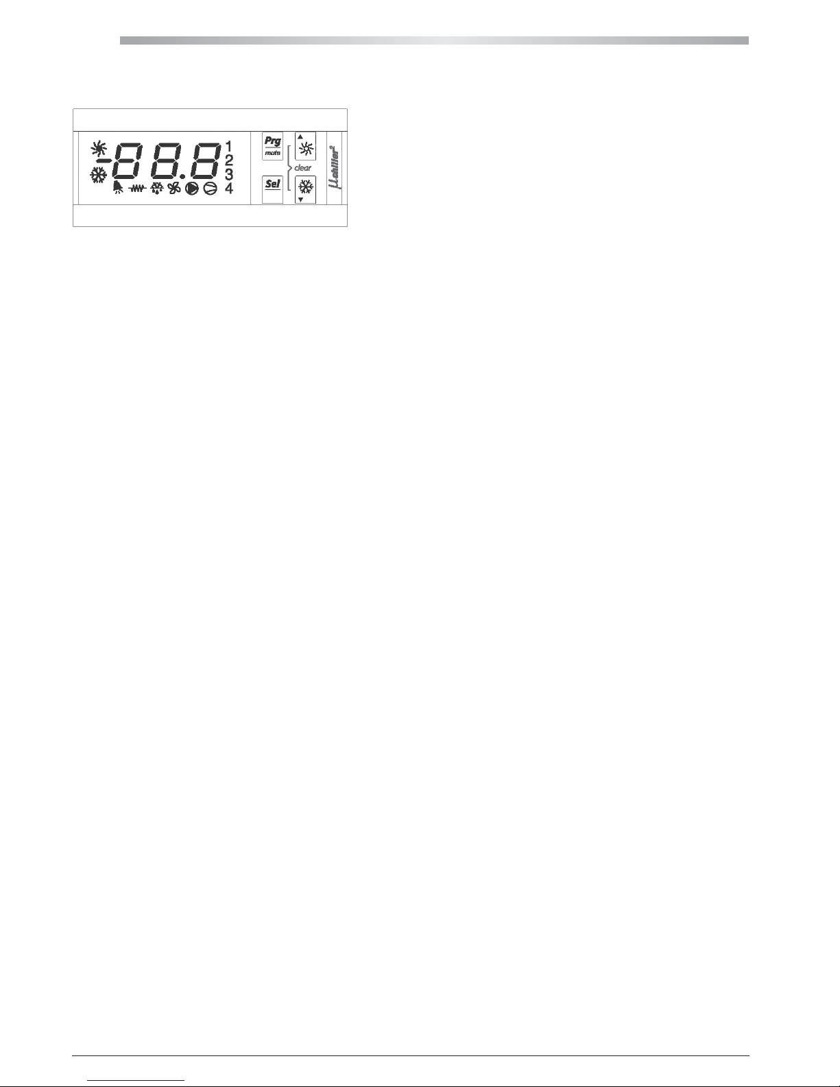
The display comprises 3 digits.
In normal operating conditions, the value displayed corresponds to the temperature read by the "Win" sensor, i.e. the unit's inlet water temperature.
Page 31
31
All copying, even partial, of this manual is strictly forbiddenRG66007169 - Rev 00
5 MICROPROCESSOR CONTROL
5.2 USING THE CONTROL PANEL
5.2.2 INFORMATION ABOUT EQUIPMENT STATUS
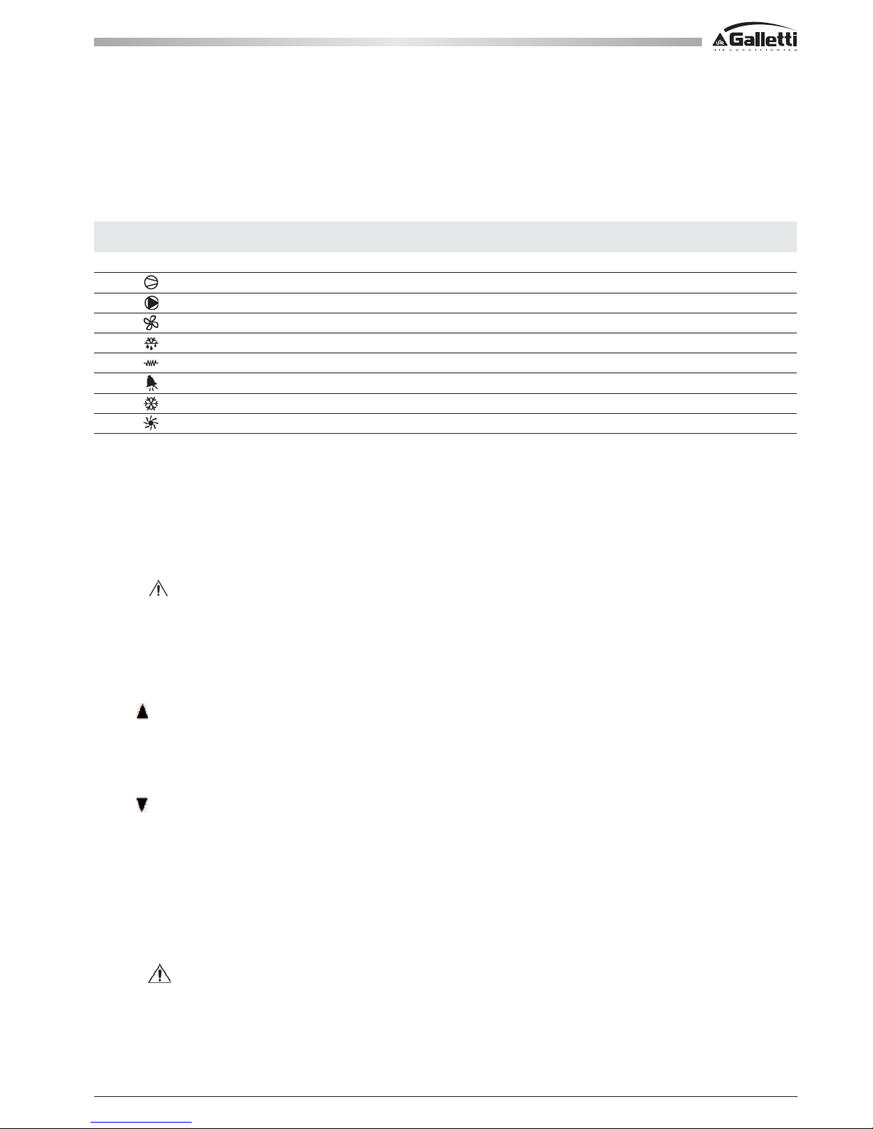
Information regarding the status of the unit is provided by means of LEDs on the display.
Meaning of LEDs on the display:
5.3 SWITCHING ON AND OFF AND CHANGINGTHE OPERATING MODE
The unit may be switched on and off from the control panel installed on the unit itself.
To enable remote ON-OFF switching from the PCDS or via an external switch (not supplied) connected to terminals 18-30 (normally jumpered) it is necessar y
to change parameter H7) from 00 to 01. (carry out the procedure of section 5.3.4, though having access from unit –H-).
Remote ON/OFF open: unit OFF (keyboard disabled)
Remote ON/OFF closed: unit ON (possibility to switch the unit ON and OFF from the keyboard)
Warning
Where remote ON-OFF switching is enabled (H7 = 01), after a power failure occurs and power is restored the unit will go into the mode
indicated by the remote input without considering any changes that have been made from the unit control panel
That is:
remote ON/OFF open: the unit remains Off
remote ON/OFF closed: the unit starts again
5.3.1 SWITCHING THE UNIT ON AND OFF IN THE COOLING MODE
Pressing
for more than 5 seconds allows the unit to be switched on or off in the cooling mode.
It is not possible to change over directly from the cooling mode to the heating mode: to do so it is necessary to select the heating mode using the PCDS
remote control (accessory) or open terminal bridge 19-30 on the electric control board (see section 5.3.3).
5.3.2 SWITCHING THE UNIT ON AND OFF IN THE HEATING MODE (MPE H HEAT PUMP MODEL ONLY)
Pressing
for more than 5 seconds allows the heating mode to be activated or deactivated.
It is not possible to change over directly from the heating mode to the cooling mode: to do so it is necessary to select the cooling mode using the PCDS
remote control (accessory) or close terminal bridge 19-30 on the electric control board (see section 5.3.3).
5.3.3 CHANGING THE OPERATING MODE
The unit leaving the factory has been configured for a fast, easy connection to the PCDS remote control (accessory), which enables the user to change the
operating mode and turn the unit on and off from a distance.
If the unit is not equipped with this accessory, to select the operating mode it is necessary to use terminals 19-30 on the electric control board as follows:
- terminals 19-30 closed for cooling
- terminals 19-30 open for heating
Warning
Only specialised personnel may access the electric control board. Therefore, to enable the user to switch the unit on and off and change
the operating mode safely and conveniently from a distance, it is recommended to install a PCDS remote control (or remote switches outside the unit).
SIMBOL COLOR MEANING
with LED ON with LED OFF
1 Amber Compressor 1 ON Start up request
Amber Compressor 1 ON
Amber Pump ON Start up request
Amber Condenser fan ON
Amber Defrost active Defrost request
Amber heater ON
Red Alarm active
Amber Chiller mode (P6=1) Chiller mode request (P6=1)
Amber Heat pump mode (P6=1) Heat pump mode request (P6=1)
Page 32
MPE
32
All copying, even partial, of this manual is strictly forbidden RG66007169 - Rev 00
5 MICROPROCESSOR CONTROL
5.3 SWITCHING ON AND OFF AND CHANGINGTHE OPERATING MODE
5.3.4 Changing the operating mode from the keyboard on the unit.
However, it is possible to configure the electronic control in such a way to allow the operating mode to be changed simply by pressing keys on the unit itself:
to this end it is necessary to change the value of the “H6” programming parameter as described below.
Warning
Do not change the values of the other parameters; this could undermine the efficiency of the unit and its safety devices.
This operation should be left in the hands of specialised personnel or a Galletti service centre.
1: Hold the “Prg” and “sel” keys pressed together for, at least, 5 s;
2: the heating and cooling simbol adn the figure “00” are displayed;
3: use the arrows to set the password 66 and confirm by pressing “sel”;
4: use the arrows to select the parameter menu (S-P) and press “sel”;
5: use the arrows to select the -H- parameter group and press “sel”;
6: use the arrows to selec the H6 parameter and press “sel” to display its value;
7: use the arrows to set the 0 value and press “sel” to confirm;
8: press “Prg” to return to the previous menu;
9: to save the modifications, press “Prg” repeatedly until reaching the main menu.
NOTE:
a: The parameters that have been modified without being confirmed using the “sel” button return to the previous value
b: If no operations are performed on the keypad for 60 seconds, the controller exits the parameter modification menu by timeout and the
changes are cancelled.
With this new configuration, the operating mode can be changed only from the keypad on the unit itself (or from the PCD remote control panel – accessory
which remotely duplicates all its functions); terminals 19-30 will no longer have any effect.
5.4 DISPLAY AND SETTING OF OPERATING PARAMETERS
In normal operating conditions, the display will show the temperature of the water entering the unit.
Holding the "sel" key pressed for more than 5 seconds is possible to move on the parameter groups and, always with "sel", you can enter in the available
parameters and values.
NB: Press "sel" to store the newly set parameters and exit the procedure; pressing "Prg" to exit without saving the changes
Warning
If no key is pressed within 60 seconds from the activation of the procedure, the control will return to the normal operating mode without
memorising any parameter changes.
5.4.1 PARAMETERS
Code Description
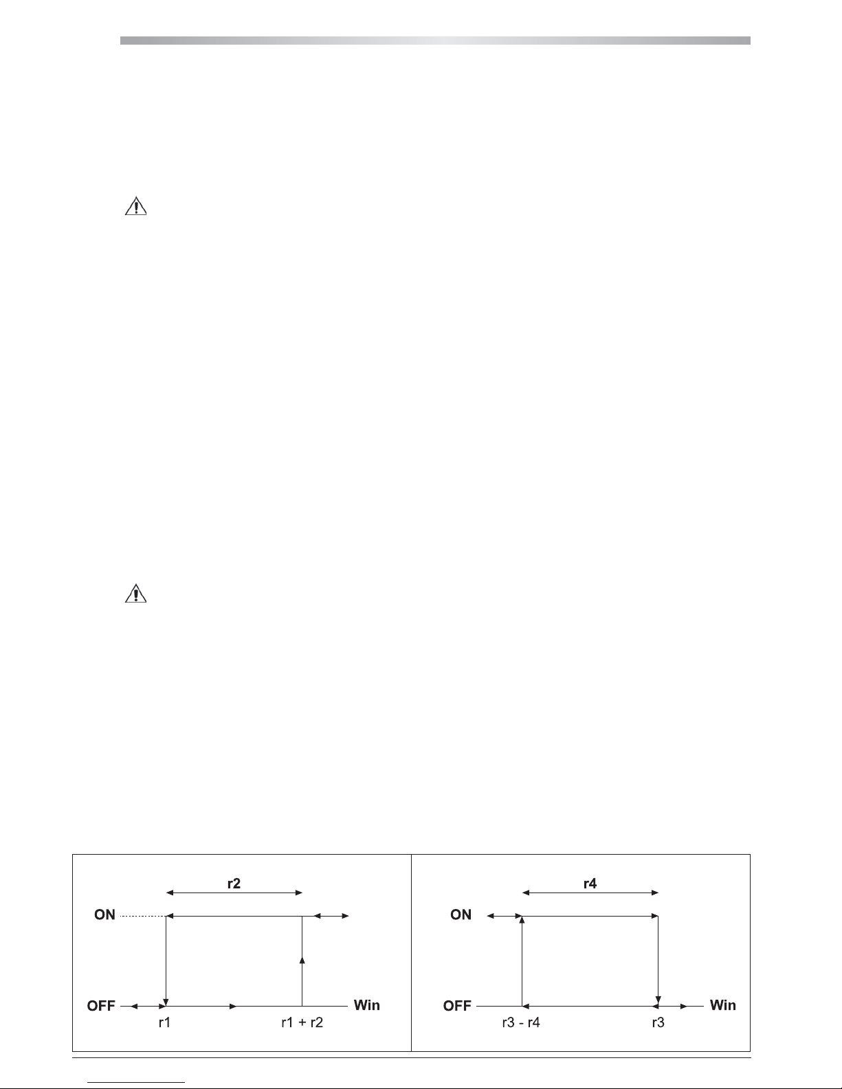
r1 Cooling set point (may be changed);
r2 Cooling set-point differential (may be changed);
r3 Heating set point (may be changed);
r4 Heating set-point differential (may be changed);
b02 Outlet water temperature (read only);
b04 Heat exchanger pressure probe (only for MPE units with condensation control or for MPE H - read only);
c10 Total hours of compressor operation (read only);
c15 Total hours of pump operation (read only).
5.5 REGULATION LOGIC
The graphs show the operating logic of the thermostat.
cooling mode heating mode
Page 33
33
All copying, even partial, of this manual is strictly forbiddenRG66007169 - Rev 00
5 MICROPROCESSOR CONTROL
5.6 SET POINT COMPENSATION
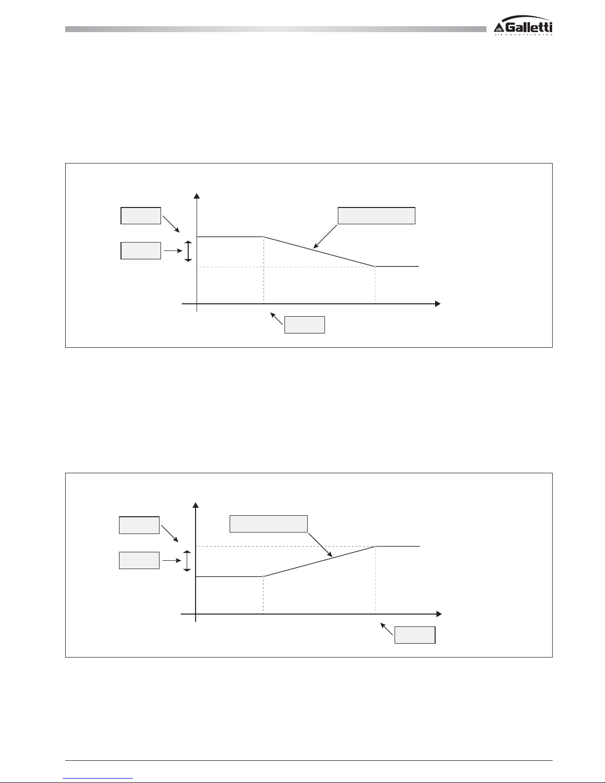
Operating setpoint correction depending on outdoor temperature.
COOLING ONLY UNITS
This logic, though not implemented as a standard feature in this type of unit, may be used to reduce its consumption of energy when outdoor temperatures
are less hot, situations in which the demand for cooling may be assumed to be lower. This logic could adjust the setpoint in the following manner:
NB: the setpoint programmed by the user (par. r1), based on how the temperature offset configuration parameters are defined, will be used without corrections
in low-demand situations.
In other situations, the setpoint actually being used to control the unit will thus not be displayable as a parameter on the controller; such a situation might
however mislead the end user into making an unsuitable setpoint adjustment.
HEAT PUMP UNITS
Such units provide for the offset logic to be used in the heating mode in order to reduce the working setpoint as the outdoor temperature decreases.
The chiller will thus remain within the working range.
Based on the set parameters, the winter setpoint will follow the following logic:
NB: changing any of the offset parameters in the heating mode will have the effect of changing the entire logic; any such change must thus be studied so
as to avoid unit malfunctioning.
Slope par. r17
par. r19
par. r18
par. r1
15.0
12.0
30.0 35.0
outdoor
temperature (°C)
SetPoint
[°C]
Slope par. r31
par. r20
par. r18
par. r3
45.0
30.0
-10.0 7.0
outdoor
temperature (°C)
SetPoint
[°C]
Page 34

MPE
34
All copying, even partial, of this manual is strictly forbidden RG66007169 - Rev 00
5 MICROPROCESSOR CONTROL
5.7 SIGNALS AND ALARMS
LIST OF INDICATIONS
d1 Defrost status (MPE H only)
During the defrosting cycle, the message "d1" is displayed in turn with the inlet water temperature (Win).
dF1 Defrost error (MPE H only)
If the defrosting cycle ends because the maximum time has elapsed, not because the temperature threshold has been reached, the message "dF1" will
be displayed. To deactivate the message, it is necessary to carry out the alarm cancellation procedure or another successfully completed defrosting
cycle.
The alarm relay is not activated.
LIST OF ALARMS
When an alarm is triggered, the alarm code is displayed alternately with the inlet temperature (Win).
HP1: High pressure
The electronic control causes the compressor to shut down immediately, the alarm relay is activated and the display starts flashing. The alarm must be
manually reset.
LP1: Low pressure
The alarm causes the compressor to shut down immediately or prevents it from starting, the alarm relay is activated and the display starts flashing.
The alarm must be manually reset.
FL: Water differential pressure switch
The alarm causes the pump, compressor and fan to shut down, the alarm relay is activated and the display starts flashing. The alarm is automatically reset.
A1: Antifreeze
The alarm is triggered by the evaporator outlet water temperature sensor (Wout).
The alarm causes the compressor and fan to shut down immediately, the alarm relay is activated and the display starts flashing. The alarm must be manually
reset.
EPr, EPb: Eeprom error alarm
It indicates that a problem has occurred in the saving of parameters in the non-volatile memory of the unit (EEPROM). If the code shown is EPr, the unit
will continue to function until the next time the power supply is cut off. If the error is still present when the power supply is restored, the display will start
flashing with the digits EPb and the unit will not start.
The alarm is automatically reset.
E1, E2, E4: Sensor alarms
When a sensor alarm is triggered, the compressor, fans and pump are deactivated; the alarm relay is activated and the display starts flashing.
E1 Inlet water sensor;
E2 Outlet water sensor;
E4 pressure probe (only for MPE units with optional condensation control or MPE H).
The alarm is automatically reset.
ELS, EHS: Error due to high or low supply voltage
If the supply voltage is too low, the message ELS will appear; if it is too high EHS is displayed. In such conditions, the proper functioning of the unit is no
longer guaranteed. If the EHS alarm is tripped, the compressor, pump and fan will be shut down.
The alarm is automatically reset.
EL1: Error due to line "disturbance"
It appears if "strong noise" is present in the power supply.
5.7.1 ALARM RESET
When alarms are reset:
- the alarm relay is deactivated;
- the temperature shown on the display stops flashing;
- the alarm code will cease being displayed.
In the case of automatically reset alarms, this will occur as soon as the cause of the alarm is eliminated;
In the case of manually reset alarms, it is necessary press
and together for 5 seconds.
If the cause of the malfunctioning persists, the alarm will again be signalled.
Page 35
35
-15
-10
-5
0
5
10
15
20
25
30
35
40
45
50
-6 -4 -2 0 2 4 6 8 10 12 14 16 18
Tbs
1
T
W2
opz 1
opz 1+2
opz 1+2 opz 1+2
EEV
EEV
STD
opz 2
All copying, even partial, of this manual is strictly forbiddenRG66007169 - Rev 00
6 OPERATING LIMITS
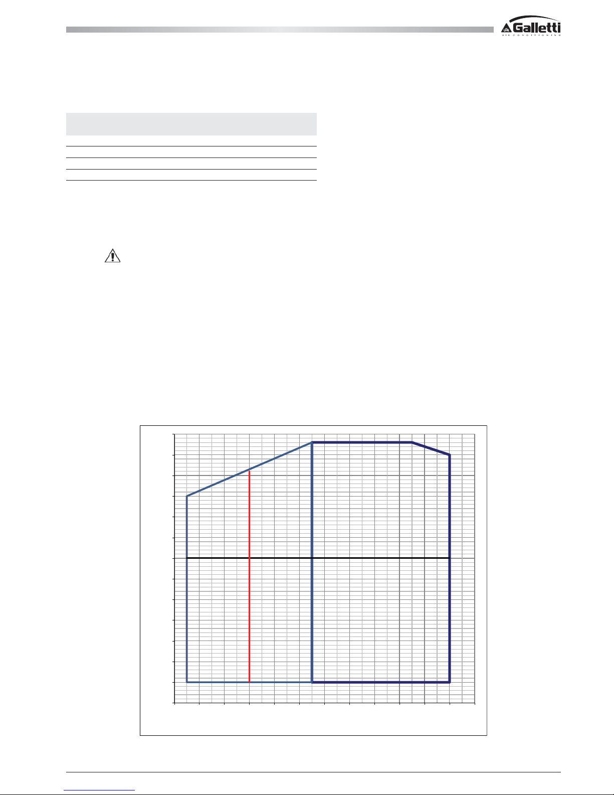
The graphs below illustrate the operating limits of MPE units (in the case of continuous operation) in relation to the outlet water temperature and outdoor
air temperature.
6.1 OPERATING LIMITS IN CHILLER MODE
Tbs1 Outdoor temperature (dry bulb)
Tw 2 Outlet water temperature
OPZ 1 Condensing control
OPZ 2 Glycol + low temperature option
OPZ 1+2 Condensation control + glycol + low temperature option
EEV Electronic expansion valve
STD Standard
Warning
The units are designed to work with water and air temperatures falling within the range defined by the operating limits.
Attempting to operate the units beyond these limits could cause irreparable damage to the units themselves.
1 For transitory periods (e.g. equipment start up) values up to 25 °C are allowed
2 Value that may be reached only for outdoor air temperatures exceeding 0°C.
3 With condensation control: Outdoor air T min -10 °C
OPERATING LIMITS CHILLER HEAT PUMP
MIN MAX MIN MAX
Inlet water temperature (°C) 8 20
1
25 42
Outlet water temperature (°C) 5 15 28 53
2
Thermal differential of water (°C) 3 8 3 8
Outdoor air temperature (°C) 153 45 -10 20
Page 36
MPE
36
20
25
30
35
40
45
50
55
-15 -10 -5 0 5 10 15 20 25 30 35 40
T
W2
Temperatura Aria esterna
F08 = 10
F09 = 2
F03 = 20
EEV
GAIN 5
int time 100
EEV + CC
OUTDOOR AIR TEMPERATURE
All copying, even partial, of this manual is strictly forbidden RG66007169 - Rev 00
6 OPERATING LIMITS
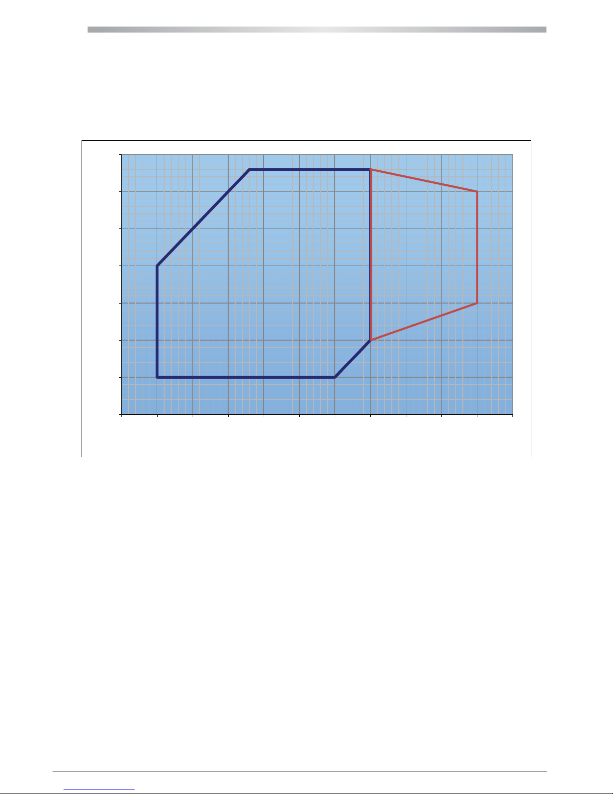
6.2 OPERATING LIMITS IN HEAT PUMP MODE
RH Relative humidity of outdoor air
Tbs1 Outdoor temperature (dry bulb)
Tw 2 Outlet water temperature
6.3 THERMAL CARRYING FLUID
The units belonging to the MPE series can work with mixtures of water and up to 30% ethylene glycol.
Page 37
37
All copying, even partial, of this manual is strictly forbiddenRG66007169 - Rev 00
7 CONTROL AND SAFETY DEVICES
All the control and safety devices are set and tested in the factory before the unit is dispatched.
7.1 CONTROL DEVICES
7.1.1 SERVICE THERMOSTAT
The service thermostat activates and deactivates the compressor according to the demand for chilled water (cooling mode) or heated water (heat pump
mode), as determined by a sensor installed on the water exchanger inlet. This device is governed by the microprocessor control (see also the chapter
regarding the microprocessor).
7.1.2 CONTROL DEVICE SETTINGS
Control devices Set point min max differenzial
Service thermostat °C 11,5 8 20 2
(outlet water temp. cooling mode)
Service thermostat °C 45 25 47 3
(outlet water temp. heat pump mode)
7.2 SAFETY DEVICES
7.2.1 HIGH PRESSURE SWITCH
The high pressure switch stops the compressor when the delivery pressure exceeds the set value.
7.2.2 REFRIGERANT CIRCUIT SAFETY VALVE (NOT AVAILABLE FOR MPE 09-15)
The safety valve is triggered in the event of a malfunctioning of the high pressure switch or in case of fire.
Warning
The safety valve is situated in the compressor compartment inside the unit. Never attempt to access internal components of the unit
until you have disconnected the power supply.
7.2.3 LOW PRESSURE SWITCH
The low pressure switch stops the compressor when the intake pressure falls below the set value.
7.2.4 ANTI-RECYCLE TIMER
The function of the timer is to prevent excessively frequent compressor starts and stops. This device is a function included in the microprocessor control;
it prevents the compressor from starting up again after a stop until a set period of time has elapsed (approximately 5 minutes).
7.2.5 ANTIFREEZE THERMOSTAT
The antifreeze thermostat situated at the evaporator outlet performs a dual function: it prevents ice from forming in the evaporator in the event of an
excessive decrease in the water flow; it stops the unit in the event of a failure of the service thermostat.
This device is governed by the microprocessor control (see also the chapter regarding the microprocessor).
7.2.6 WATER DIFFERENTIAL PRESSURE SWITCH
The water differential pressure switch stops the unit in the event of an excessive reduction in the water flow, thus protecting it from the formation of ice
(chiller operation) and excessively high condensation temperatures (heat pump operation)
7.2.7 WATER SAFETY VALVE
The water safety valve opens when the pressure within the water circuit reaches a level that may cause damage to the unit.
7.2.8 SAFETY DEVICE SETTINGS
Safety device activation differential resetting
Maximum pressure switch (bars) 42 Automatic
Refrigerant safety valve (bars) 45
Minimum pressure switch (bars) 2 Automatic
Antifreeze thermostat (°C) 3 3 Manual
Water differential pressure switch (bars) 0,050 0 Automatic
Water safety valve (bars) 4
Page 38

MPE
38
All copying, even partial, of this manual is strictly forbidden RG66007169 - Rev 00
8 ROUTINE MAINTENANCE AND CHECKS
It is recommended to carry out periodic checks of the safety devices (pressure switches and safety valves) and verify the absence of refrigerant leaks.
After the first start-up, the periodic checks must be carried out in conformity with the schedule and the manners provided for by current national
regulations.
To keep the unit in good working order and guarantee the expected levels of performance and safety, it is necessary to carry out some periodic routine
checks: some may be performed directly by the user while others must be carried out solely by specialised personnel.
8.1 CHECKS TO BE PERFORMED BY THE USER
The checks and operations described in this section may be easily performed by the user, provided that the latter shows a minimum of attention.
- Remove any dirt that has built up around the coil or objects trapped in the mesh protecting the coil itself (leaves, paper etc., to be carried out monthly).
Warning
Be especially careful when working in proximity to finned coils since the aluminium fins are extremely sharp and can cause cuts.
- Check the level of water in the circuit using the water pressure gauge, which should indicate a pressure of about 1.5 bars (monthly).
- Check that the escape pipe of the water safety valve is tightly secured.
- Check the water circuit for leaks (monthly).
- If the unit is to remain out of service for a long time, drain the water (or other fluid present in the circuit) from the pipes and the unit itself.
This is indispensable if during the period of quiescence the ambient temperature is expected to fall below the freezing point of the fluid used (seasonal
operation).
Drain the unit and parts of the circuit subject to the risk of freezing by opening the RS (optional) emptying tap.
Before placing the unit back in service at the start of the season, refill the water circuit as directed in section 1.4
- Check that the noise emissions of the unit are regular (monthly).
- If necessary, release the pump rotor ("P" and "S" version)
8.2 CHECKS AND MAINTENANCE TO BE PERFORMED BY SPECIALISED PERSONNEL
Warnings
Important! All the operations described in this section MUST ALWAYS BE PERFORMED BY QUALIFIED PERSONNEL.
Warning
Before carrying out any work on the unit or accessing internal par ts, make sure you have disconnected it from the mains electricity
supply.
Warning
The upper part of the compressor casing and the outlet pipe reach high temperatures. Be especially careful when working in their
vicinity.
Warning
Be especially careful when working in proximity to the finned coils: the aluminium fins are extremely sharp and can cause cuts.
Important! After completing maintenance jobs, always replace the panels enclosing the unit and secure them with the fastening screws provided.
The checks and operations described in this section must be carried out on a yearly basis by specialised personnel.
- Check the electric control board terminals to ensure that they are securely tightened: the movable and fixed contacts of the circuit breakers must be
periodically cleaned and replaced whenever they show signs of deterioration.
- Check the compressor and pipes for oil leaks.
- Check the efficiency of the water differential pressure switch.
- Clean the metal filters mounted in the water pipes.
- Clean the finned coil by aiming a jet of compressed air in a direction opposite to the outflow of air, taking care not to bend the fins.
9 RETIRING THE UNIT
When the unit has reached the end of its working life and needs to removed and replaced, a series of operations should be carried out:
- the refrigerant gas it contains should be recovered by specialised personnel and sent to a waste collection facility;
- the lubricating oil in the compressor should also be recovered by specialised personnel and sent to a waste collection facility;
- if they cannot be reused, the framework and components should be scrapped and separated according to the type of material: this applies especially
for the considerable quantities of copper, aluminium and steel present in the unit.
This will make the job of waste collection, disposal and recycling facilities easier and minimise the environmental impact of the dismantling.
Installation and maintenance should be carried out by technical personnel qualified for this type of machine, in compliance with current safety regulations.
When receiving the unit please check its state verifying if any damage occurred during the transport.
For installation and use of possible accessories please refer to the pertinent technical sheets.
Page 39
39
All copying, even partial, of this manual is strictly forbiddenRG66007169 - Rev 00
10 TECHNICAL FEATURES
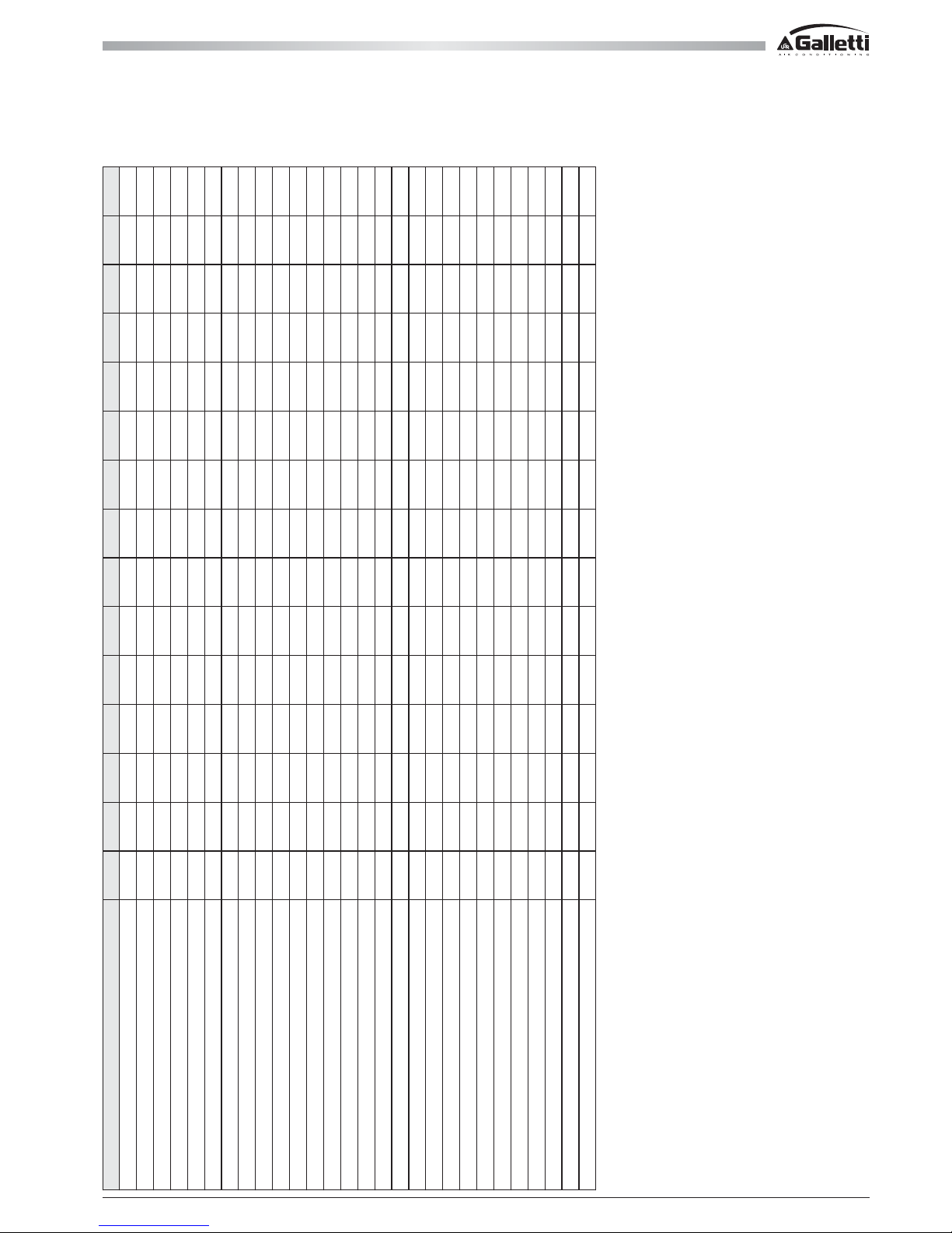
10.1 WATER CHILLERS RATED TECHNICAL DATA
* Weights referred to version including pump and buffer tank
- Cooling capacity: outdoor air temperature 35°C, water temperature 12°C / 7°C
- Sound power level measured according to standards ISO 3741 - ISO 3744 and EN 29614-1
- Sound pressure level measured at a distance of 10 m and a height of 1.5 m above the ground in a free field (fan side).
- The maximum electrical input is the mains electricity that must be available in order for the unit to work.
- The maximum current absorption refers to the current that will trigger the internal safety devices of the unit. It is the maximum current allowed in the unit. This value may never be exceeded; it must
be used as a reference for determining the size of the power supply line and the related safety devices (refer to the wiring diagram supplied with the units).
MPE-C 004 M 005 M 007 M 008 M 008 010 M 010 013 015 018 020 024 027 028
Power supply V-ph-Hz 230-1-50 230-1-50 230-1-50 230-1-50 400-3-50 230-1-50 400-3-50 400-3-50 400-3-50 400-3-50 400-3-50 400-3-50 400-3-50 400-3-50
Cooling capacity kW 4,1 5,1 6,7 8,4 8,4 9,3 9,3 12,9 15,0 17,2 19,6 23,8 26,6 28,1
MPE CB Total power input kW 1,3 1,7 2,3 3,3 3,1 3,2 3,2 4,2 5,2 6,3 7,1 8,1 9,3 8,7
EER 3,1 3,0 3,0 2,5 2,7 2,9 2,9 3,1 2,9 2,7 2,8 2,9 2,9 3,2
ESEER 3,5 3,4 3,3 3,0 3,4 3,4 3,4 3,7 3,5 3,3 3,2 3,4 3,4 3,8
MPE CP CS Total power input kW 1,5 1,8 2,4 3,5 3,2 3,6 3,6 4,5 5,5 6,7 7,5 8,5 9,7 9,2
Maximum power input kW 2,0 2,3 3,0 5,0 5,0 5,1 7,2 8,9 10,5 12,5 13,6 14,5 18,0 18,3
Maximum current absorption A 9,8 11,6 15,3 24,2 9,2 26,3 14,4 17,4 20,0 24,3 26,2 27,6 33,6 35,5
Starting absorbed current A 38 44 63 98 49 99 50 65 68 75 104 158 132 133
n° of compressors / circuits 1 / 1 1 / 1 1 / 1 1 / 1 1 / 1 1 / 1 1 / 1 1 / 1 1 / 1 1 / 1 1 / 1 1 / 1 1 / 1 1 / 1
Refrigerant charge kg 1,5 1,5 2,0 2,1 2,1 2,9 2,9 4,0 4,1 3,7 4,2 5,8 6,0 7,5
Low/high pressure switch bar 2 / 42 2 / 42 2 / 42 2 / 42 2 / 42 2 / 42 2 / 42 2 / 42 2 / 42 2 / 42 2 / 42 2 / 42 2 / 42 2 / 42
n° of axial fan 11111222244442
Air flow m3/h 3.635 3.635 3.406 3.406 3.406 7.385 7.385 6.939 6.939 9.990 9.990 9.307 9.307 16.276
Water flow l/h 707 877 1.146 1.445 1.445 1.591 1.591 2.219 2.577 2.958 3.373 4.094 4.575 4.833
Diameter of hydrualic connections pollici111111 1/41 1/41 1/41 1/41 1/41 1/41 1/41 1/41 1/4
Water side pressure drop kPa 24666343461385151493440
Available pressure head kPa 63 61 57 53 53 116 116 83 103 129 123 116 124 143
Water content escluding optionals dm3 1,5 1,5 1,5 1,5 1,5 3,0 3,0 3,0 3,0 4,0 4,0 4,0 4,0 5,5
Expansion tank dm311111555555558
Buffer tank dm3 20 20 20 20 20 30 30 30 30 50 50 50 50 125
Height mm 758 758 758 758 758 1250 1250 1250 1250 1300 1300 1300 1300 1485
Length mm 960 960 960 960 960 1220 1220 1220 1220 1565 1565 1565 1565 1990
Depth mm 450 450 450 450 450 560 560 560 560 600 600 600 600 950
Sound power level dB(A) 66 66 67
67 67 69 69 69 69 71 71 72 72 73
Sound pressure level dB(A) 38 38 39 39 39 41 41 41 41 43 43 44 44 45
Transport weight * kg 98 100 107 110 110 202 202 209 209 260 260 280 285 370
Operating weight * kg 92 94 101 104 104 228 228 235 235 306 296 327 332 492
Page 40
MPE
40
All copying, even partial, of this manual is strictly forbidden RG66007169 - Rev 00
* Weights referred to version including pump and buffer tank
- Cooling capacity: outdoor air temperature 35°C, water temperature 12°C / 7°C
- Sound power level measured according to standards ISO 3741 - ISO 3744 and EN 29614-1
- Sound pressure level measured at a distance of 10 m and a height of 1.5 m above the ground in a free field (fan side).
- The maximum electrical input is the mains electricity that must be available in order for the unit to work.
- The maximum current absorption refers to the current that will trigger the internal safety devices of the unit. It is the maximum current allowed in the unit. This value may never be exceeded; it must
be used as a reference for determining the size of the power supply line and the related safety devices (refer to the wiring diagram supplied with the units).
10 TECHNICAL FEATURES
10.1 WATER CHILLERS RATED TECHNICAL DATA
MPE-C 032 035 040 054 066 T30 T34 T40 T45 T54 T61 T69 T76
Power supply V-ph-Hz 400-3-50 400-3-50 400-3-50 400-3-50 400-3-50 400-3-50 400-3-50 400-3-50 400-3-50 400-3N-50 400-3N-50 400-3N-50 400-3N-50
Cooling capacity kW 31,5 35,0 39,7 51,4 66,1 30,0 34,1 39,6 44,6 54,6 61,9 69,8 76,1
MPE CB Total power input kW 10,1 11,5 12,8 17,8 24,1 10,4 12,6 13,6 16,4 18,3 21,2 23,6 27,5
EER 3,1 3,0 3,1 3,0 2,7 2,9 2,7 2,9 2,7 3,0 2,9 3,0 2,8
ESEER 3,6 3,6 3,7 3,6 3,3 4,2 4,1 4,1 4,0 4,0 4,0 4,2 4,2
MPE CP CS Total power input kW 10,6 12,1 13,3 18,7 25,0 11,0 13,1 14,2 16,9 19,6 22,5 24,9 28,8
Maximum power input kW 18,9 21,8 22,4 22,7 23,3 20,9 24,4 26,6 30,8 27,0 29,9 32,3 39,4
Maximum current absorption A 36,5 41,5 42,5 45,2 46,2 39,9 45,9 49,7 56,7 48,0 53,0 57,0 69,0
Starting absorbed current A 166 161 163 163 165 86 96 127 130 177 187 202 229
n° of compressors / circuits 1 / 1 1 / 1 1 / 1 1 / 1 1 / 1 2 / 1 2 / 1 2 / 1 2 / 1 2 / 1 2 / 1 2 / 1 2 / 1
Refrigerant charge kg 7,5 7,8 10,8 13 15,0 7,8 7,8 10,9 10,9 11,0 11,0 16,0 16,0
Low/high pressure switch bar 2 / 42 2 / 42 2 / 42 2 / 42 2 / 42 2 / 42 2 / 42 2 / 42 2 / 42 2 / 42 2 / 42 2 / 42 2 / 42
n° of axial fan 22222 22224444
Air flow m3/h 16.276 16.276 15.776 20000 20000 16.276 16.276 15.776 15.776 24930 24930 24354 24354
Water flow l/h 5.421 6.021 6.823 9305 11376 5.160 5.857 6.806 7.663 9391 10647 12006 13089
Diameter of hydrualic connections pollici 1 1/4 1 1/4 1 1/4 1 1/4 1 1/4 1 1/4 1 1/4 1 1/4 1 1/4 2 2 2 2
Water side pressure drop kPa 51 41 43 60 60 30,01 38 45 57 56 69 55 64
Available pressure head kPa 126 130 119 110 95 150 134 117 97 138 120 128 114
Water content escluding optionals dm3 5,5 5,5 5,5 7 8 5,5 5,5 5,5 5,5 7 8 11 12
Expansion tank dm388888 88888888
Buffer tank dm3 125 125 125 125 125 125 125 125 125 125 125 125 125
Height mm 1485 1485 1485 1485 1485 1485 1485 1485 1485 1735 1735 1735 1735
Length mm 1990 1990 1990 1990 1990 1990 1990 1990 1990 2091 2091 2091 2091
Depth mm 950 950 950 950 950 950 950 950 950 1183 1183 1183 1183
Sound power level dB(A) 73 73 75 78 78 72 72 72 72 81 81 81 81
Sound pressure level dB(A) 45 45 47 50 50 44 44 44 44 53 53 53 53
Transport weight * kg 370 390 390 500 530 410 410 430 430 557 692 692 786
Operating weight * kg 492 513 513 620 650 532 533 553 553 665 800 800 894
Page 41
41
All copying, even partial, of this manual is strictly forbiddenRG66007169 - Rev 00
10 TECHNICAL FEATURES
10.2 HEAT PUMPS RATED TECHNICAL DATA
* Weights referred to version including pump and buffer tank
- Cooling capacity: outdoor air temperature 35°C, water temperature 12°C / 7°C
- Heating capacity: outdoor air temperature 7°C dry bulb and 6.2°C wet bulb, water temperature 40°C/45°C
- Sound power level measured according to standards ISO 3741 - ISO 3744 and EN 29614-1
- Sound pressure level measured at a distance of 10 m and a height of 1.5 m above the ground in a free field (fan side).
- The maximum electrical input is the mains electricity that must be available in order for the unit to work.
- The maximum current absorption refers to the current that will trigger the internal safety devices of the unit. It is the maximum current allowed in the unit. This value may never be exceeded; it
must be used as a reference for determining the size of the power supply line and the related safety devices (refer to the wiring diagram supplied with the units).
MPE-H 004 M 005 M 007 M 008 M 008 010 M 010 013 015 018 020 024 027 028
Power supply V-ph-Hz 230-1-50 230-1-50 230-1-50 230-1-50 400-3-50 230-1-50 400-3-50 400-3-50 400-3-50 400-3-50 400-3-50 400-3-50 400-3-50 400-3-50
Cooling capacity kW 4,0 5,0 6,5 8,2 8,2 9,1 9,1 12,6 14,7 16,9 19,2 23,3 26,1 27,5
MPE HB Cooling power input kW 1,3 1,7 2,3 3,3 3,1 3,2 3,2 4,2 5,2 6,3 7,1 8,1 9,3 8,7
EER 3,0 2,9 2,9 2,5 2,7 2,8 2,8 3,0 2,8 2,7 2,7 2,9 2,8 3,2
ESEER 3,5 3,3 3,3 2,9 3,3 3,3 3,3 3,6 3,5 3,2 3,2 3,4 3,3 3,7
MPE HP - HS Cooling power input kW 1,5 1,8 2,4 3,5 3,2 3,6 3,6 4,5 5,5 6,7 7,5 8,5 9,7 9,2
Heating capacity kW 4,7 5,9 7,8 10,2 9,9 10,9 10,9 15,1 17,6 20,0 23,0 27,2 30,0 31,4
MPE HB Heating power input kW 1,5 1,8 2,4 3,6 3,2 3,6 3,6 4,7 5,5 6,6 7,2 8,1 8,9 9,1
COP 3,2 3,2 3,2 2,8 3,1 3,0 3,0 3,2 3,2 3,0 3,2 3,3 3,4 3,4
MPE HP - HS Heating power input kW 1,6 1,9 2,5 3,7 3,4 4,0 4,0 5,1 5,9 7,0 7,5 8,5 9,3 9,7
Maximum power input kW 2,0 2,3 3,0 5,0 5,0 5,1 7,2 8,9 10,5 12,5 13,6 14,5 18,0 18,3
Maximum current absorption A 9,8 11,6 15,3 24,2 9,2 26,3 14,4 17,4 20,0 24,3 26,2 27,6 33,6 35,5
Starting absorbed current A 38 44 63 98 49 99 50 65 68 75 104 158 132 133
n° of compressors / circuits 1 / 1 1 / 1 1 / 1 1 / 1 1 / 1 1 / 1 1 / 1 1 / 1 1 / 1 1 / 1 1 / 1 1 / 1 1 / 1 1 / 1
Refrigerant charge kg 1,47 1,48 2,04 2,09 2,09 2,87 2,87 3,99 4,11 3,67 4,23 5,8 6,0 7,5
Low/high pressure switch bar 2 / 42 2 / 42 2 / 42 2 / 42 2 / 42 2 / 42 2 / 42 2 / 42 2 / 42 2 / 42 2 / 42 2 / 42 2 / 42 2 / 42
n° of axial fan 11111222244442
Air flow m3/h 3.635 3.635 3.406 3.406 3.406 7.385 7.385 6.939 6.939 9.990 9.990 9.307 9.307 16.276
Water flow in cooling mode l/h 707 877 1.146 1.445 1.445 1.591 1.591 2.219 2.577 2.958 3.373 4.094 4.575 4.833
Water flow in heat pump l/h 811 1.008 1.337 1.755 1.711 1.869 1.869 2.595 3.027 3.445 3.949 4.670 5.156 5.396
Diameter of hydrualic connections “ 1 1 1 1 1 1 1/4 1 1/4 1 1/4 1 1/4 1 1/4 1 1/4 1 1/4 1 1/4 1 1/4
Water pressure drop (cooling) kPa 2 4 6 6 6 34 34 61 38 51 51 49 34 40
Water pressure drop (heating) kPa 3 4 8 8 8 45 45 83 51 69 69 62 43 49
Available pressure head (cooling) kPa 63 61 57 53 53 116 116 83 103 129 123 116 124 143
Available pressure head (heating) kPa 62 59 53 48
48 102 102 57 86 104 97 95 107 128
Water content escluding optionals dm3 1,5 1,5 1,5 1,5 1,5 3,0 3,0 3,0 3,0 4,0 4,0 4,0 4,0 5,5
Expansion tank dm311111555555558
Buffer tank dm3 n.d. n.d. n.d. n.d. n.d. 30 30 30 30 50 50 50 50 125
Height mm 758 758 758 758 758 1250 1250 1250 1250 1300 1300 1300 1300 1485
Length mm 960 960 960 960 960 1220 1220 1220 1220 1565 1565 1565 1565 1990
Depth mm 450 450 450 450 450 560 560 560 560 600 600 600 600 950
Sound power level dB(A) 66 66 67 67 67 69 69 69 69 71 71 72 72 73
Sound pressure level dB(A) 38 38 39 39 39 41 41 41 41 43 43 44 44 45
Transport weight * kg
103 105 112 115 115 212 212 219 220 273 273 295 300 400
Operating weight * kg
97 99 106 109 109 238 238 245 246 319 309 342 347 522
Page 42
MPE
42
All copying, even partial, of this manual is strictly forbidden RG66007169 - Rev 00
10 TECHNICAL FEATURES
10.2 HEAT PUMPS RATED TECHNICAL DATA
* Weights referred to version including pump and buffer tank
- Cooling capacity: outdoor air temperature 35°C, water temperature 12°C / 7°C
- Heating capacity: outdoor air temperature 7°C dry bulb and 6.2°C wet bulb, water temperature 40°C/45°C
- Sound power level measured according to standards ISO 3741 - ISO 3744 and EN 29614-1
- Sound pressure level measured at a distance of 10 m and a height of 1.5 m above the ground in a free field (fan side).
- The maximum electrical input is the mains electricity that must be available in order for the unit to work.
- The maximum current absorption refers to the current that will trigger the internal safety devices of the unit. It is the maximum current allowed in the unit. This value may never be exceeded; it
must be used as a reference for determining the size of the power supply line and the related safety devices (refer to the wiring diagram supplied with the units).
MPE-H 032 035 040 054 066 T30 T34 T40 T45 T54 T61 T69 T76
Power supply V-ph-Hz 400-3-50 400-3-50 400-3-50 400-3-50 400-3-50 400-3-50 400-3-50 400-3-50 400-3-50 400-3N-50 400-3N-50 400-3N-50 400-3N-50
Cooling capacity kW 30,9 34,3 38,9 52,0 62,8 29,4 33,4 38,8 43,7 53,5 60,7 68,5 74,6
MPE HB Cooling power input kW 10,1 11,5 12,8 17,8 24,1 10,4 12,6 13,6 16,4 18,3 21,2 23,6 27,5
EER 3,1 3,0 3,0 2,9 2,6 2,8 2,7 2,8 2,7 2,9 2,9 2,9 2,7
ESEER 3,6 3,5 3,6 3,5 3,2 4,1 4,0 4,1 4,0 4,0 4,0 4,2 4,2
MPE HP - HS Cooling power input kW 10,6 12,1 13,3 18,7 25,0 11,0 13,1 14,2 16,9 19,6 22,5 24,9 28,8
Heating capacity kW 35,6 39,3 45,2 60,8 75,3 34,5 39,4 46,5 52,7 59,9 67,5 77,0 84,8
MPE HB Heating power input kW 10,4 11,6 13,1 18,3 23,1 10,9 12,8 14,0 16,3 18,5 21,5 23,4 26,8
COP 3,4 3,4 3,4 3,3 3,3 3,2 3,1 3,3 3,2 3,2 3,1 3,3 3,2
MPE HP - HS Heating power input kW 11,0 12,1 13,7 19,2 24,0 11,4 13,4 14,5 16,8 19,8 22,8 24,7 28,1
Maximum power input kW 18,9 21,8 22,4 22,7 23,3 20,9 24,4 26,6 30,8 27,0 29,9 32,3 39,4
Maximum current absorption A 36,5 41,5 42,5 45,2 46,2 39,9 45,9 49,7 56,7 48,2 53,2 57,2 69,2
Starting absorbed current A 166 161 163 163 165 86 96 127 130 177 187 202 229
n° of compressors / circuits 1 / 1 1 / 1 1 / 1 1 / 1 1 / 1 2 / 1 2 / 1 2 / 1 2 / 1 2 / 1 2 / 1 2 / 1 2 / 1
Refrigerant charge kg 7,5 7,8 10,8 13 16,0 7,8 7,8 10,9 10,9 12,8 12,8 16,3 16,3
Low/high pressure switch bar 2 / 42 2 / 42 2 / 42 2 / 42 2 / 42 2 / 42 2 / 42 2 / 42 2 / 42 2 / 42 2 / 42 2 / 42 2 / 42
n° of axial fan 22222 22224444
Air flow m3/h 16.276 16.276 15.776 20000 20000 16.276 16.276 15.776 15.776 24930 24930 24354 24354
Water flow in cooling mode l/h 5.421 6.021 6.823 8944 10802 5.160 5.857 6.806 7.663 9202 10440 11782 12831
Water flow in heat pump l/h 6.120 6.756 7.769 10456 12953 5.935 6.779 7.996 9.067 10303 11610 13244 14579
Diameter of hydrualic connections “ 1 1/4 1 1/4 1 1/4 1 1/4 1 1/4 1 1/4 1 1/4 1 1/4 1 1/4 2 2 2 2
Water pressure drop (cooling) kPa 51 41 43 60 60 30 38 45 57 56 69 55 64
Water pressure drop (heating) kPa 63 50 54 80 80 39 51 57 73 60 77 59 71
Available pressure head (cooling) kPa 126 130 119 112 99 150 134 117 97 138 120 128 114
Available pressure head (heating) kPa 107 113 99 80 61 133 112 93 67 130 120 110 100
Water content escluding optionals dm3 5,5 5,5 5,5 7,0 8,0 5,5 5,5 5,5 5,5 7,0 8,0 11,0 12,0
Expansion tank
dm388888 88888888
Buffer tank dm3 125 125 125 125 125 125 125 125 125 125 125 125 125
Height mm 1485 1485 1485 1485 1485 1485 1485 1485 1485 1735 1735 1735 1735
Length mm 1990 1990 1990 1990 1990 1990 1990 1990 1990 2091 2091 2091 2091
Depth mm 950 950 950 950 950 950 950 950 950 1183 1183 1183 1183
Sound power level dB(A) 73 73 75 78 78 72 72 72 72 81 81 81 81
Sound pressure level dB(A) 45 45 47 50 50 44 44 44 44 53 53 53 53
Transport weight * kg
400 420 420
530 560
430 430 430 450
660 702 702 792
Operating weight * kg
522 543 543
650 680
552 552 553 573
768 810 810 900
Page 43
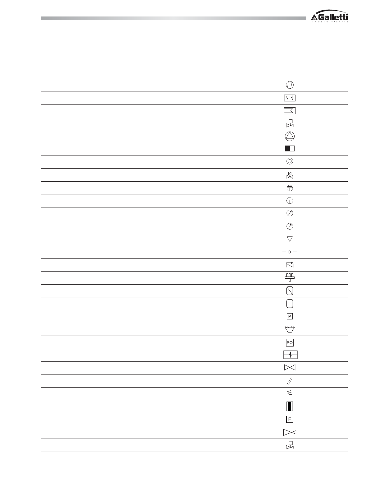
43
All copying, even partial, of this manual is strictly forbiddenRG66007169 - Rev 00
11 COOLING CIRCUITS
N° COMPONENT SIMBOL
1 Compressor
2 Evaporator
3 Condensator
4 Thermostatic valve
5 Electrical fan
6 Filter
7 Sight glass
8 Solenoid valve
9 High pressure switch
10 Low pressure switch
11 High pressure gauge
12 Low pressure gauge
13 Service connection
14 Diff. pressure switch
15 Check valve
16 4 Way diversion valve
17 Liquid separator
18 Liquid receiver
19 Pressure transducer
20 Liquid distributor
21 Oil pressure switch
22 Desuperheater
23 Shut-Off valve
24 Pocket
25 Security valve
26 Fusible plug
27 Flow switc
28 Restrictor
29 Electronic expansion valve
LEGEND
Page 44
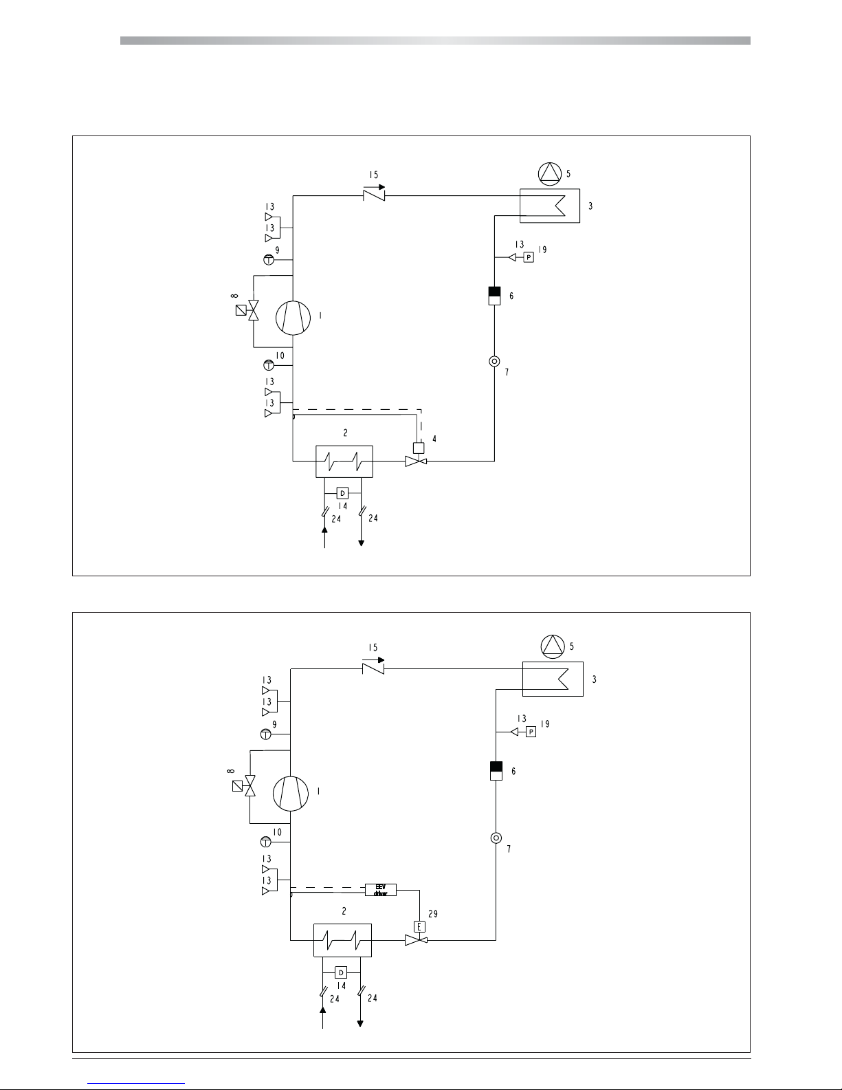
MPE
44
All copying, even partial, of this manual is strictly forbidden RG66007169 - Rev 00
11 COOLING CIRCUIT
11.2 MPE 04 ÷ 07 WATER CHILLER COOLING CIRCUIT WITH ELECTRONIC VALVE
11.1 MPE 04 ÷ 07 WATER CHILLER COOLING CIRCUIT
Page 45
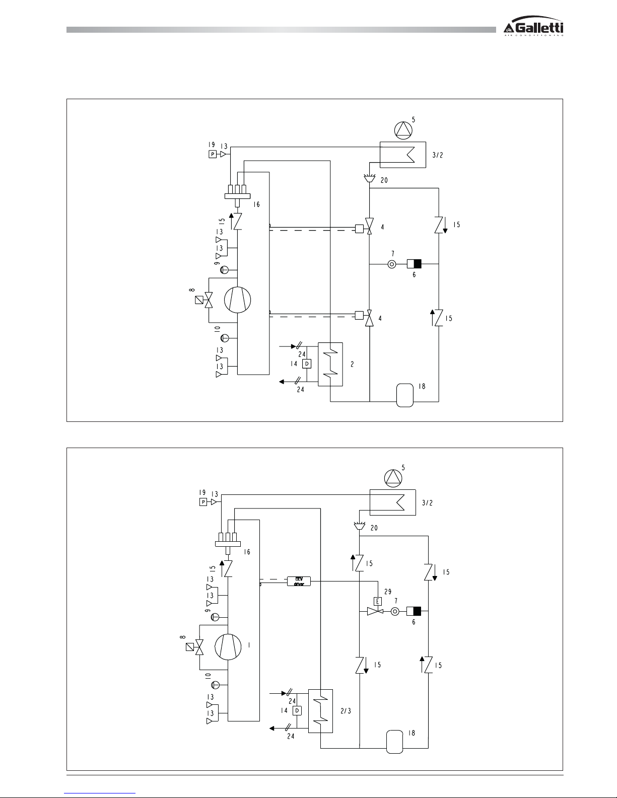
45
All copying, even partial, of this manual is strictly forbiddenRG66007169 - Rev 00
11 COOLING CIRCUIT
11.4 MPE H 04 ÷ 07 HEAT PUMP COOLING CIRCUIT WITH ELECTRONIC VALVE
11.3 MPE H 04 ÷ 07 HEAT PUMP COOLING CIRCUIT
Page 46
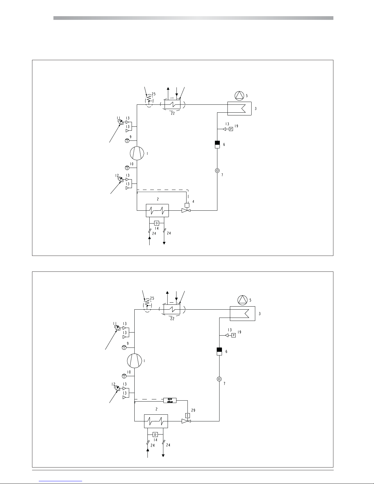
MPE
46
All copying, even partial, of this manual is strictly forbidden RG66007169 - Rev 00
11 COOLING CIRCUIT
11.6 MPE 08 ÷ 27 WATER CHILLER COOLING CIRCUIT WITH ELECTRONIC VALVE
11.5 MPE 08 ÷ 27 WATER CHILLER COOLING CIRCUIT
NOT PRESENT IN MPE 08-15
NOT PRESENT IN MPE 08-15
OPTIONAL
NOT AVAILABLE FOR MPE 08
OPTIONAL
NOT AVAILABLE FOR MPE 08
OPTIONAL
NOT AVAILABLE
FOR MPE 08
OPTIONAL
NOT AVAILABLE
FOR MPE 08
OPTIONAL
NOT AVAILABLE
FOR MPE 08
OPTIONAL
NOT AVAILABLE
FOR MPE 08
Page 47
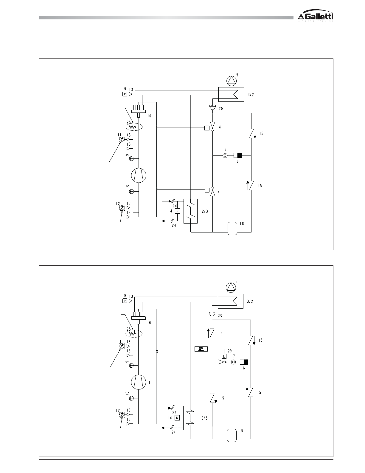
47
All copying, even partial, of this manual is strictly forbiddenRG66007169 - Rev 00
11 COOLING CIRCUIT
11.8 MPE H 08 ÷ 27 HEAT PUMP COOLING CIRCUIT WITH ELECTRONIC VALVE
11.7 MPE H 08 ÷ 27 HEAT PUMP COOLING CIRCUIT
NOT PRESENT IN MPE 08-15
NOT PRESENT IN MPE 08-15
OPTIONAL
NOT AVAILABLE
FOR MPE 08
OPTIONAL
NOT AVAILABLE
FOR MPE 08
OPTIONAL
NOT AVAILABLE
FOR MPE 08
OPTIONAL
NOT AVAILABLE
FOR MPE 08
Page 48
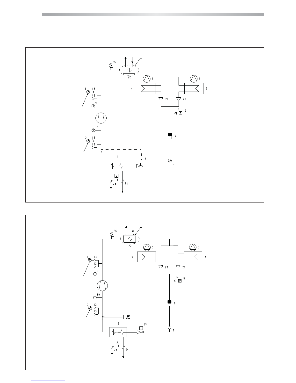
MPE
48
All copying, even partial, of this manual is strictly forbidden RG66007169 - Rev 00
11 COOLING CIRCUIT
11.10 MPE 28 ÷ 66 WATER CHILLER COOLING CIRCUIT WITH ELECTRONIC VALVE
11.9 MPE 28 ÷ 66 WATER CHILLER COOLING CIRCUIT
OPTIONAL
OPTIONAL
OPTIONAL
OPTIONAL
OPTIONAL
OPTIONAL
Page 49
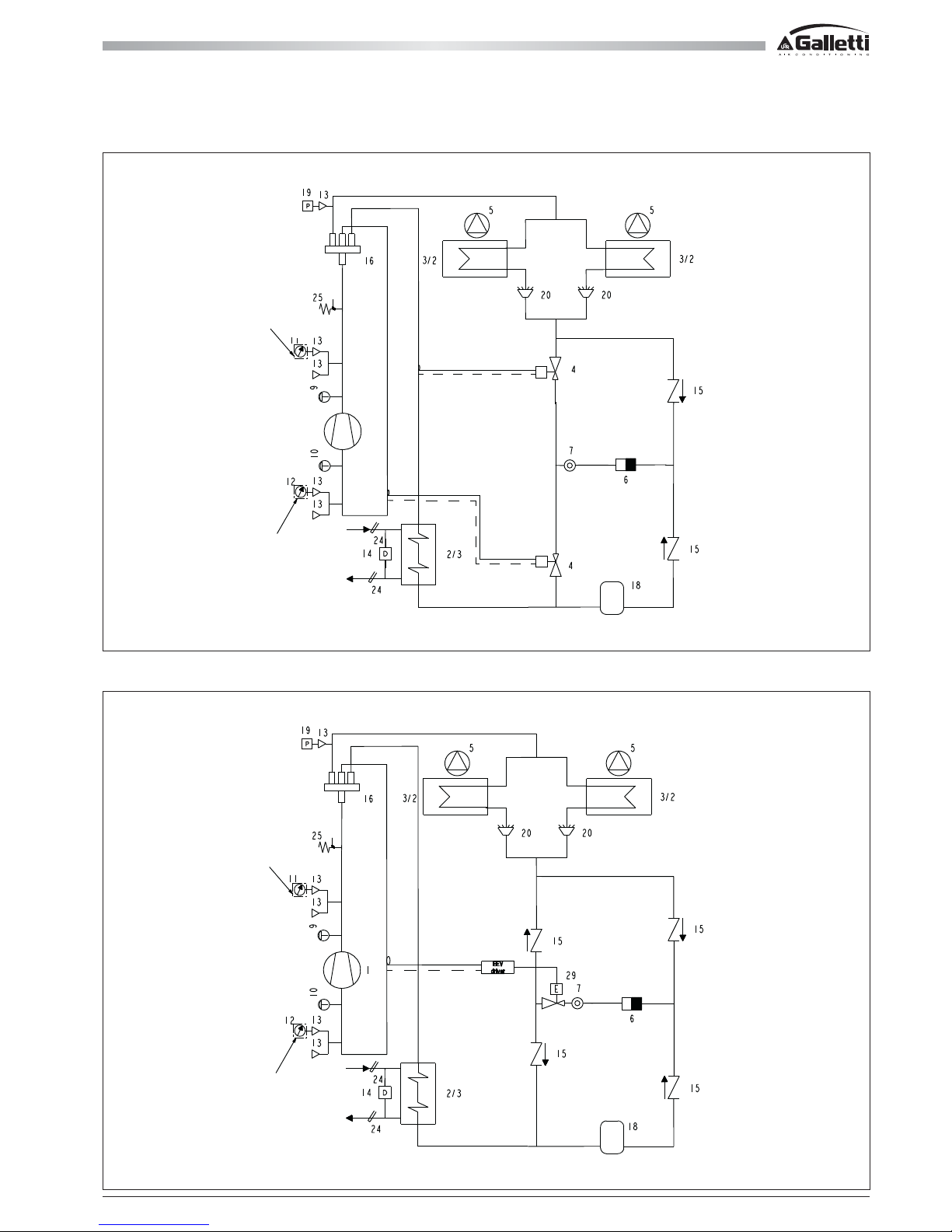
49
All copying, even partial, of this manual is strictly forbiddenRG66007169 - Rev 00
11 COOLING CIRCUIT
11.12 MPE H 28 ÷ 66 HEAT PUMP COOLING CIRCUIT WITH ELECTRONIC VALVE
11.11 MPE H 28 ÷ 66 HEAT PUMP COOLING CIRCUIT
OPTIONAL
OPTIONAL
OPTIONAL
OPTIONAL
Page 50
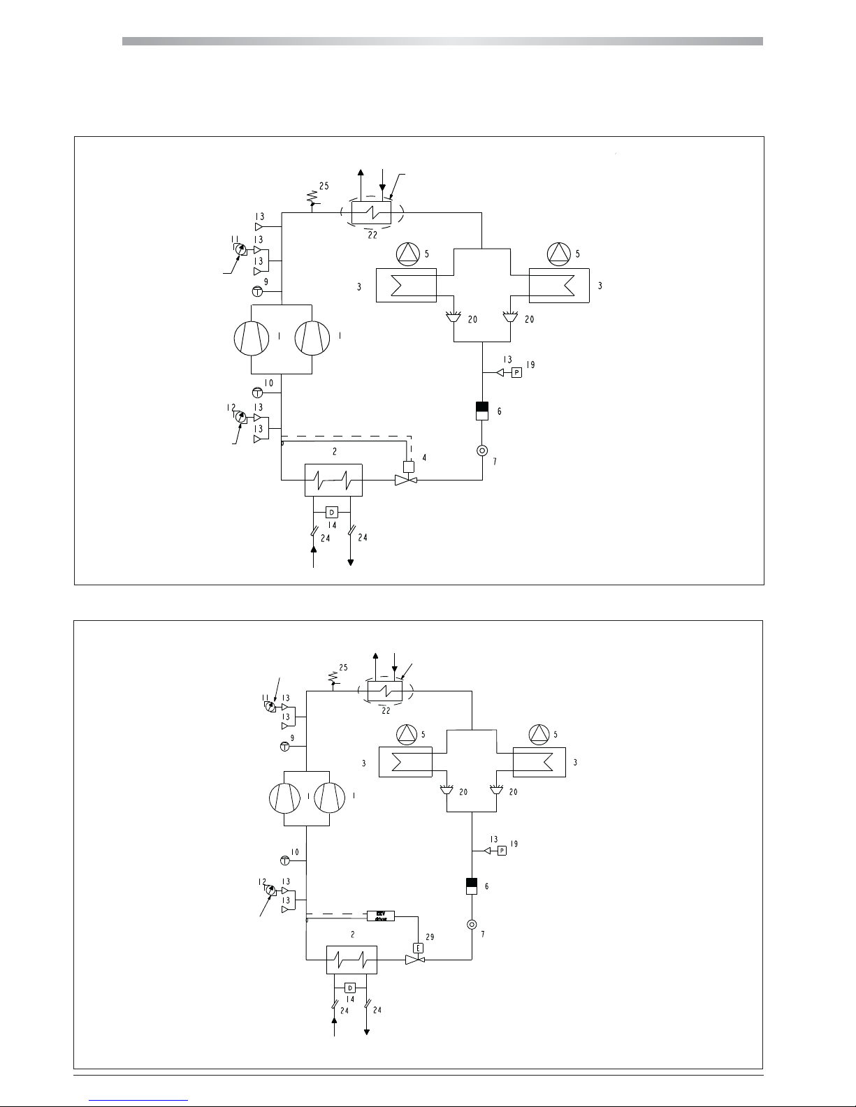
MPE
50
All copying, even partial, of this manual is strictly forbidden RG66007169 - Rev 00
11 COOLING CIRCUIT
11.14 MPE 30 ÷ 76 T HEAT PUMP COOLING CIRCUIT WITH ELECTRONIC VALVE
11.13 MPE 30 ÷ 76 T HEAT PUMP COOLING CIRCUIT
OPTIONAL
OPTIONAL
OPTIONAL
OPTIONAL
OPTIONAL
OPTIONAL
Page 51
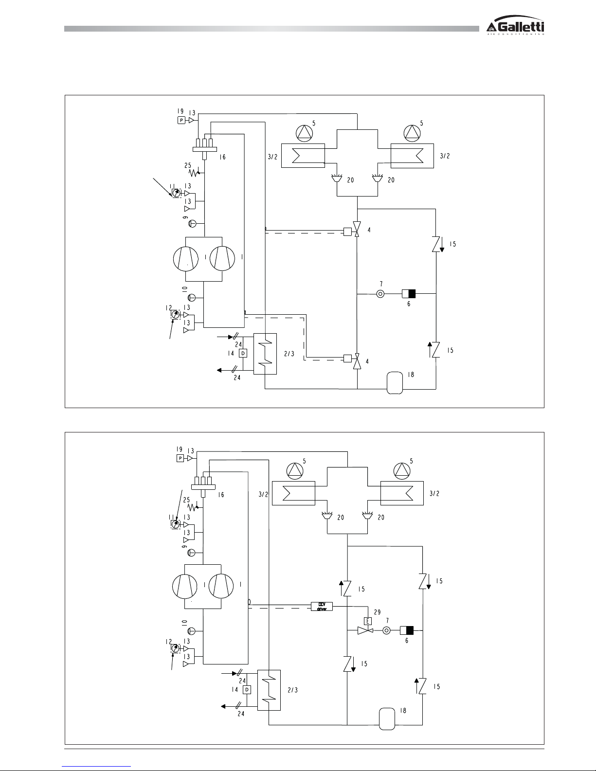
51
All copying, even partial, of this manual is strictly forbiddenRG66007169 - Rev 00
11 COOLING CIRCUIT
11.16 MPE H 30 ÷ 76 T HEAT PUMP COOLING CIRCUIT WITH ELECTRONIC VALVE
11.15 MPE H 30 ÷ 76 T HEAT PUMP COOLING CIRCUIT
OPTIONAL
OPTIONAL
OPTIONAL
OPTIONAL
Page 52
MPE
52
All copying, even partial, of this manual is strictly forbidden RG66007169 - Rev 00
12 TROUBLESHOOTING
In this section you will find a list of the most common problems that may cause the chiller unit to stop or malfunction.
Possible remedies are shown alongside a description of easily identifiable remedies.
Warning
Extreme care should be taken when performing work or repairs on the unit: overconfidence can result in injuries, even serious ones, to
inexpert individuals. Operations marked with the letter "U" can be per formed directly by the user, who must carefully follow the instructions provided
in this manual. Operations marked with the letter "S" may be performed exclusively by specialised personnel. Once the cause has been identified, you
are advised to contact a Galletti service centre or a qualified technician for help.
SYMPTOM
A The unit does not
start
B The compressor
does not start
C The compressor
starts up and
stops repeatedly
Cooling
X
X
X
X
X
X
X
X
X
X
X
X
X
X
X
X
X
X
Heating
X
X
X
X
X
X
X
X
X
X
X
X
X
X
X
X
X
X
Who can take
corrective
action
U = User
S = specialised
personnel
S
S
U
S
U
U
S
S
S
S
S
S
S
S
S
S
U
S
Possible control
panel indication
EU
EO
E1
A1
E2
L1
H1
L1
Probable cause
Faulty connection or contacts open
Wrong voltage
Not enabled by remote controls
Anti-recycle timer active
Service thermostat sensor defective
Not enabled by service thermostat.
Not enabled by antifreeze thermostat
Antifreeze sensor defective
Tripping of main circuit breaker
Not enabled by high or low pressure switch
Compressor defective
Compressor burnout or seizure
Compressor contactor deenergized
Power circuit open
Motor thermal protection open
Minimum pressure switch has tripped
Compressor contactor defective
Wrong set-point or differential setting
Lack of refrigerant
Possible remedy
Check the voltage and close the contacts
Check the efficiency of the water circulation
pump, pressure switch, bleed air from the
circuit; check whether contacts 16 and 30
on the terminal board are closed
Wait 5 minutes until the timer enables
operation
Check and replace if necessary
System at the set temperature, no demand;
check the setting
Check the water temperature
Checking the antifreeze setting
Check whether it is functioning properly
Check for the presence of short circuits in
the wiring or windings of the pump, fan and
compressor motors or in the transformer.
See items D-E
See item B
Replace the compressor
Check the voltage at either end of the
compressor contactor coil and verify the
continuity of the coil itself
Locate the cause that tripped the protection;
check for the presence of short circuits in
the wiring or windings of the pump, fan and
compressor motors or in the transformer
The compressor has operated in critical
conditions or there is insufficient refrigerant
within the circuit: check the working
conditions and make sure they fall within
the operating limits.
Refrigerant leak: refer to item G
See item E
Check and replace if necessary
Change them according to the indications
given in the tables.
See item G.
Page 53
53
All copying, even partial, of this manual is strictly forbiddenRG66007169 - Rev 00
12 TROUBLESHOOTING
SYMPTOM
D The compressor
does not start because
the maximum pressure
switch has tripped
E The compressor
does not start because
the minimum pressure
switch has tripped
F The fans do not start
Cooling
X
X
X
X
X
X
X
X
X
X
X
X
X
X
X
X
X
X
Heating
X
X
X
X
X
X
X
X
X
X
X
X
X
X
X
X
X
X
X
Who can take
corrective action
U = User
S = specialised
personnel
S
S
U
S
U
S
S
S
S
S
U
S
S
S
S
S
S
S
S
S
S
S
S
Possible control
panel indication
H1
H1
H1
H1
H1
H1
H1
H1
L1
L1
L1
L1
L1
L1
L1
L1
L1
L1
H1
L1
H1
L1
H1
L1
H1
L1
H1
L1
Probable cause
Pressure switch failure
Excessive refrigerant charge
Finned coil obstructed, insufficient air flow
Fan not working
Water circulation pump blocked
Water circulation pump defective
Presence of incondensable gas in the cooling circuit
Refrigerant filter clogged
Pressure switch failure
Unit completely empty
Finned coil obstructed, insufficient air flow
Water circulation pump blocked
Water circulation pump blocked defective
Presence of frost on the evaporating coil
Evaporator fan not working
Refrigerant filter clogged
Expansion valve is not working properly
Presence of humidity in the cooling circuit
Fan contactor deenergized (MPE only)
No power output by the fan speed control card (only
MPE H or MPE with condensation control)
The fan's internal thermal protection has tripped
Fan motor defective
Loose electrical connections
Possib le remedy
Check and replace
Discharge the excess gas
Remove dirt from the coil and any
obstacles to air flow.
See item F
Release the pump
Check the pump and replace it if
necessary.
Recharge the circuit after having drained
and evacuated it
Check and replace
Check and replace
See item G
Remove dirt from the coil
Release the pump
Check the pump and replace it if
necessary.
See item O
See item F
Check and replace
Check and replace if necessary
Replace the filter and, if necessary, dry
out the circuit and recharge
Check the voltage at either end of the
contactor coil and verify the continuity
of the coil itself
Check the contacts and replace if
necessary
Check the fan conditions and the air
temperature while the unit is running.
Check and replace if necessary
Check and fasten securely
Page 54
MPE
54
All copying, even partial, of this manual is strictly forbidden RG66007169 - Rev 00
12 TROUBLESHOOTING
SYMPTOM
G Lack of gas
I Frost in liquid pipe
downstream from a filter
L The unit works
continuously without ever
stopping
M The unit works
regularly but with an
insufficient capacity
N Frost in the
compressor intake pipe
O The defrosting cycle
is never activated
P Abnormal noises
detected in the system
Cooling
X
X
X
X
X
X
X
X
X
X
X
X
X
X
X
X
Heating
X
X
X
X
X
X
X
X
X
X
X
X
X
X
X
X
X
Who can take
corrective action
U = User
S = specialised
personnel
S
S
S
U
S
S
S
S
S
S
S
S
S
S
S
S
S
Possible control
panel indication
L1
H1
L1
Probable cause
Cooling circuit leak
Liquid filter clogged
Lack of refrigerant gas
Wrong setting of operating thermostat
Thermal overload
Compressor does not provide the rated heating capacity
Liquid filter clogged
Low level of refrigerant
4-way cycle reversing valve defective
Expansion valve is not working properly
Water circulation pump blocked
Water circulation pump defective
Low level of refrigerant
Liquid filter clogged
4-way cycle reversing valve defective
The defrost thermostat has broken down or has been
set incorrectly
The compressor is noisy
The panels vibrate
Possible remedy
Check the cooling circuit using a leak
detector after pressurising the circuit to
approximately 4 bars.
Repair, evacuate and refill.
Replace the filter
See item G
Check the setting
Reduce the thermal load
Check and replace or overhaul
Replace
See item G
Check the valve power supply and coils
and replace the valve if necessary
Check replace
Release the pump
Check the pump and replace it if necessary
See item G
Replace
Check the valve power supply and coils
and replace the valve if necessary
Check and replace if defective or change
the setting
Check and replace if necessary
Fasten properly
Page 55
55
All copying, even partial, of this manual is strictly forbiddenRG66007169 - Rev 00
NOTES
Page 56

www.galletti.it
40010 Bentivoglio (BO) Via Romagnoli 12/a Tel. 051/8908111 - Fax. 051/8908122
Company UNI EN ISO 9001 and OHSAS 18001 certified
 Loading...