

Galletti LCP041PL, LCP041PS, LCP051HS, LCP051PS, LCP051HL Installation, Use And Maintenance Manual
...Page 1
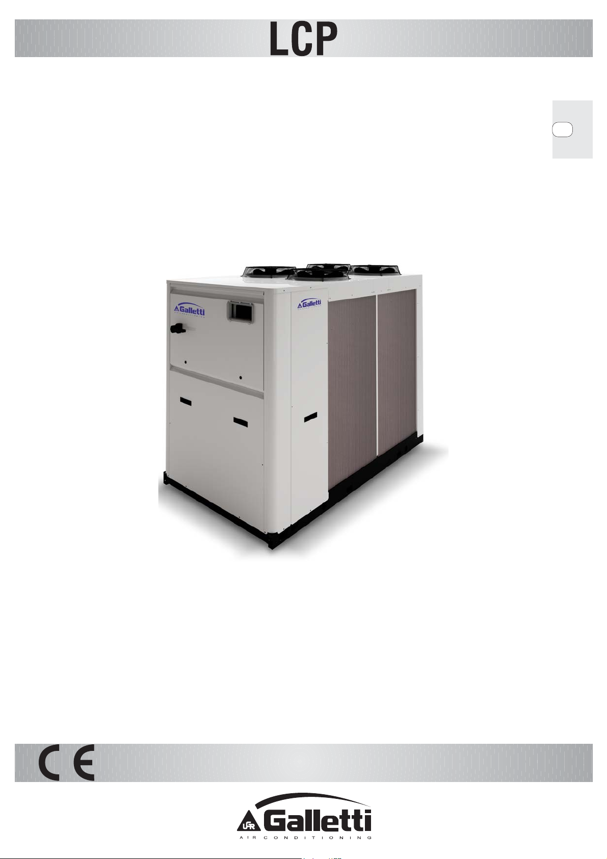
Installation use and maintenance
GB
MULTI-PURPOSE VERSION
Page 2
LCP
RG66006889-Rev.01 2
Page 3
LCP
CONTENTS
PAGE
1
THE SERIES 6
2 FIELD OF APPLICATION 11
3 GENERALITIES 11
4 INSPECTION, CONVEYANCE, SITING 12
4.1 INSPECTION 12
4.2 LIFTING AND CONVEYANCE 12
4.3 UNPACKING 13
4.4 SITING 13
5 INSTALLATION 14
5.1 INSTALLATION CLEARANCE REQUIREMENTS 14
5.2 GENERAL GUIDELINES FOR PLUMBING CONNECTIONS 15
5.3 WATER CONNECTION TO THE EVAPORATOR 16
5.4 SAFETY DEVICES ON THE HIGH PRESSURE SIDE 17
6 ELECTRICAL CONNECTIONS 18
6.1 GENERALITIES 18
6.2 ELECTRICAL CONNECTIONS OF WATER VANE OPERATED FLOW SWITCH 19
6.3 ELECTRIC CONNECTIONS OF THE CIRCULATION PUMP 19
6.4 REMOTE CONTROLS 19
6.5 REMOTE SUMMER-WINTER SWITCHING 19
7 STARTING UP 20
7.1 PRELIMINARY CHECKS 20
7.2 STARTING OPERATION 21
7.3 CHECKS DURING OPERATION 22
7.4 CHECKING THE REFRIGERANT LEVEL 22
7.5 EXPANSION VALVE (OPTIONAL) 23
7.6 STOPPING THE UNIT 24
8 OPERATING LIMITS 24
8.1 WATER FLOW TO EVAPORATOR 24
8.2 CHILLED WATER TEMPERATURE 25
8.3 OUTDOOR AIR TEMPERATURE 25
8.4 OPERATION WITH WATER AT LOW TEMPERATURES 25
9 SETTING OPERATING PARAMETERS 25
9.1 GENERALITIES 25
9.2 MAXIMUM PRESSURE SWITCH 26
9.3 MINIMUM PRESSURE SWITCH 26
9.4 SERVICE THERMOSTAT 26
9.5 ANTIFREEZE THERMOSTAT 27
RG66006889-Rev.01 3
Page 4
LCP
9.6 ANTI-RECYCLE TIMER 27
9.7 OIL DIFFERENTIAL PRESSURE SWITCH 27
10 ROUTINE MAINTENANCE AND CHECKS 27
10.1 WARNINGS 27
10.2 GENERALITIES 28
10.3 REPAIRING THE COOLING CIRCUIT 28
10.4 TIGHTNESS TEST 28
10.5 HARD VACUUM AND DRYING OF THE COOLING CIRCUIT 29
10.6 CHARGING WITH R410A REFRIGERANT 29
10.7 ENVIRONMENTAL PROTECTION 30
11 RETIRING THE UNIT 30
12 TROUBLESHOOTING 31
13 WATER PRESSURE DROPS 34
13.1 PRESSURE DROPS IN EVAPORATOR 34
13.2 PRESSURE DROPS IN HEAT RECUPERATOR 34
14 SUMMARY TECHNICAL DATA 35
14.1 STANDARD VERSION 35
14.2 LOW NOISE VERSION 37
15 SUMMARY TABLE OF WEIGHTS 39
15.1 PUMPING AND STORAGE SYSTEMS 41
RG66006889-Rev.01 4
Page 5
LCP
Declaration of conformity
The declaration of conformity is individually appended to the documents accompanying the unit,
normally placed inside the electrical enclosure.
RG66006889-Rev.01 5
Page 6
LCP
k
1 THE SERIES
Fluid chillers and heat pumps designed to cool water or mixtures of water and an antifreeze agent,
intended for civil air conditioning and industrial cooling systems. LCP chillers, available in versions with
different acoustic designs (“S”, “L”) and cooling circuit architectures (Efficiency pack 1, 4), cover a range
of cooling capacities from 51.4 to 318.1 kW, calculated with reference to standard conditions.
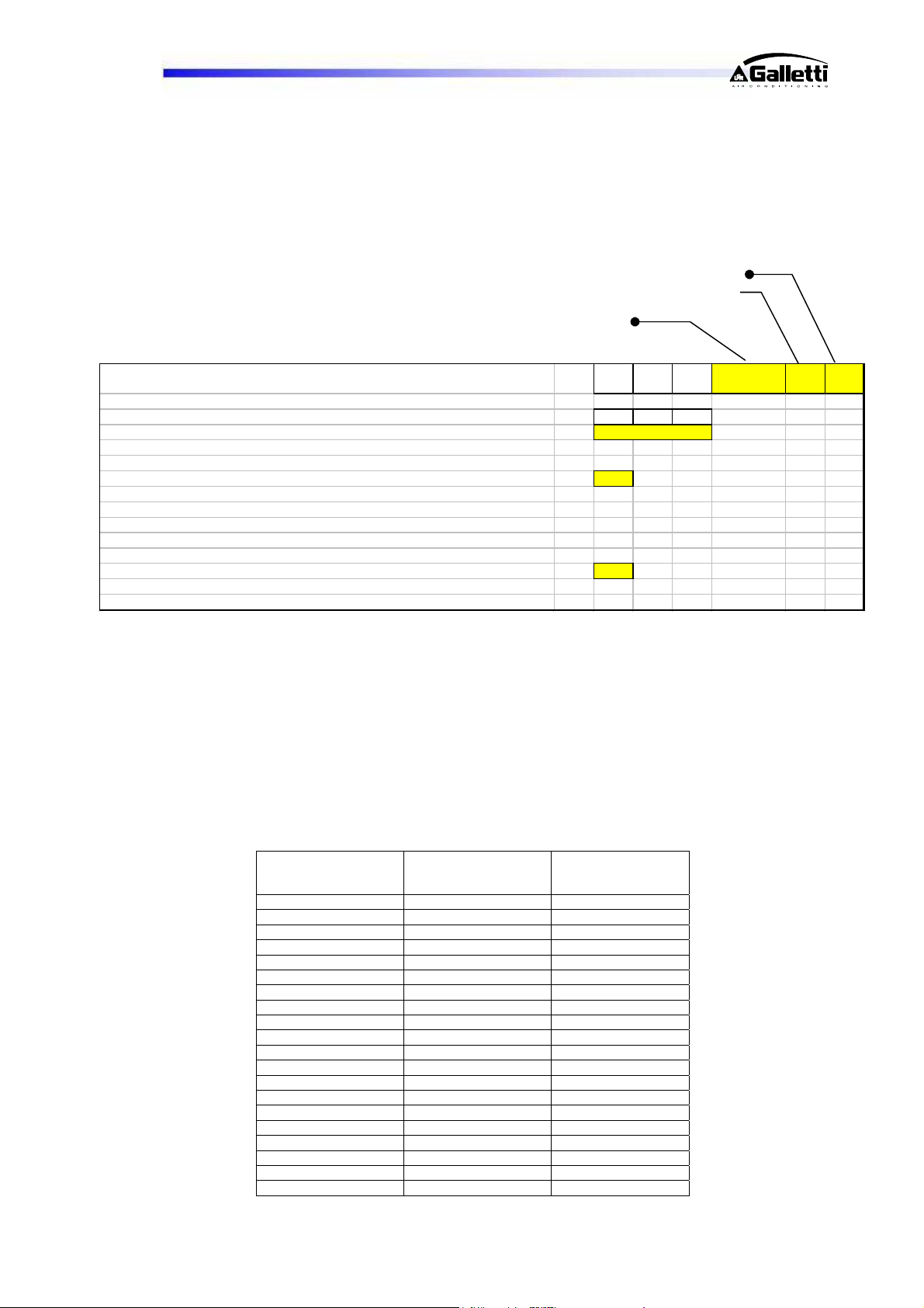
Example of product code composition:
Configuration
Size + eff. pac
Complete machine symbol L C P 104 H S
Version
Commercial name LCP
Model
Operation H
2 pipes – seasonal reversible utility (cooling/heat) + heat only utility H
4 pipes – cooling only utility + heat only utility P
Version S
Standard S
Low noise L
194
Configurations: 2 pipes - seasonal reversible utility (cooling/heat) + only heat utility → “H”
4 pipes – only cooling utility + only heat utility → “P”
Versions: Standard version → “S”
Low noise version – for a low noise impact → “L”
Efficiency Packs: Efficiency pack 1 → 2 compressors 2 refrigerant circuits
Efficiency pack 4 → 4 compressors 2 refrigerant circuits
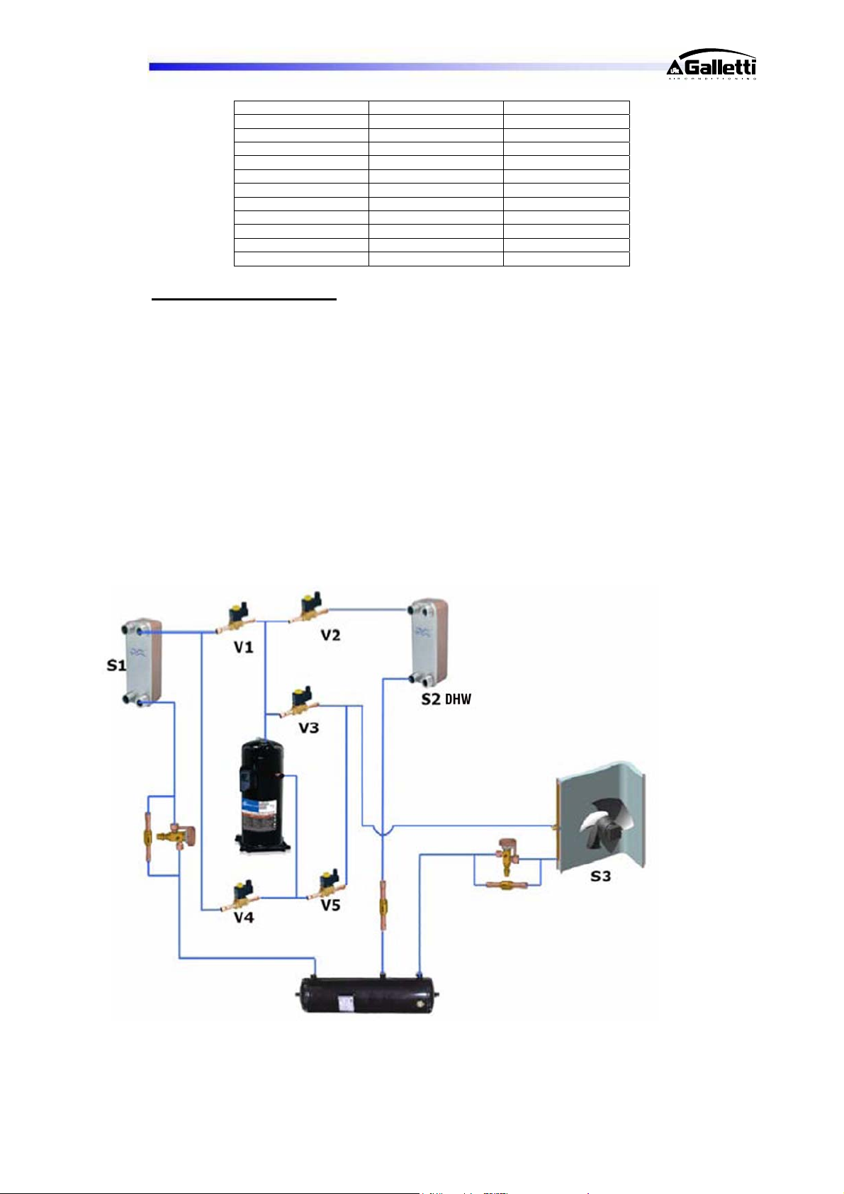
Below is a list of all possible models, broken down by efficiency pack:
Approximate
efficiency pack 1 efficiency pack 4
LCP041HS/PS - 51,4
LCP041HL/PL - 49,4
LCP051HS/PS - 56,5
LCP051HL/PL - 53,7
LCP061HS/PS - 66,4
LCP061HL/PL - 64,0
LCP071HS/PS - 74,1
LCP071HL/PL - 70,6
LCP081HS/PS - 81,6
LCP081HL/PL - 77,4
- LCP094HS/PS 99,2
- LCP094HL/PL 95,1
- LCP104HS/PS 108,4
- LCP104HL/PL 103,0
- LCP124HS/PS 130,2
- LCP124HL/PL 123,7
- LCP144HS/PS 143,3
- LCP144HL/PL 135,0
- LCP164HS/PS 161,3
- LCP164HL/PL 149,8
RG66006889-Rev.01 6
cooling capacity in
vers. [kW]
Page 7
LCP
- LCP194HS/PS 186,7
- LCP194HL/PL 181,4
- LCP214HS/PS 220,4
- LCP214HL/PL 214,8
- LCP244HS/PS 245,4
- LCP244HL/PL 238,2
- LCP274HS/PS 276,1
- LCP274HL/PL 270,1
- LCP294HS/PS 299,9
- LCP294HL/PL 291,6
- LCP324HS/PS 318,1
- LCP324HL/PL 308,7
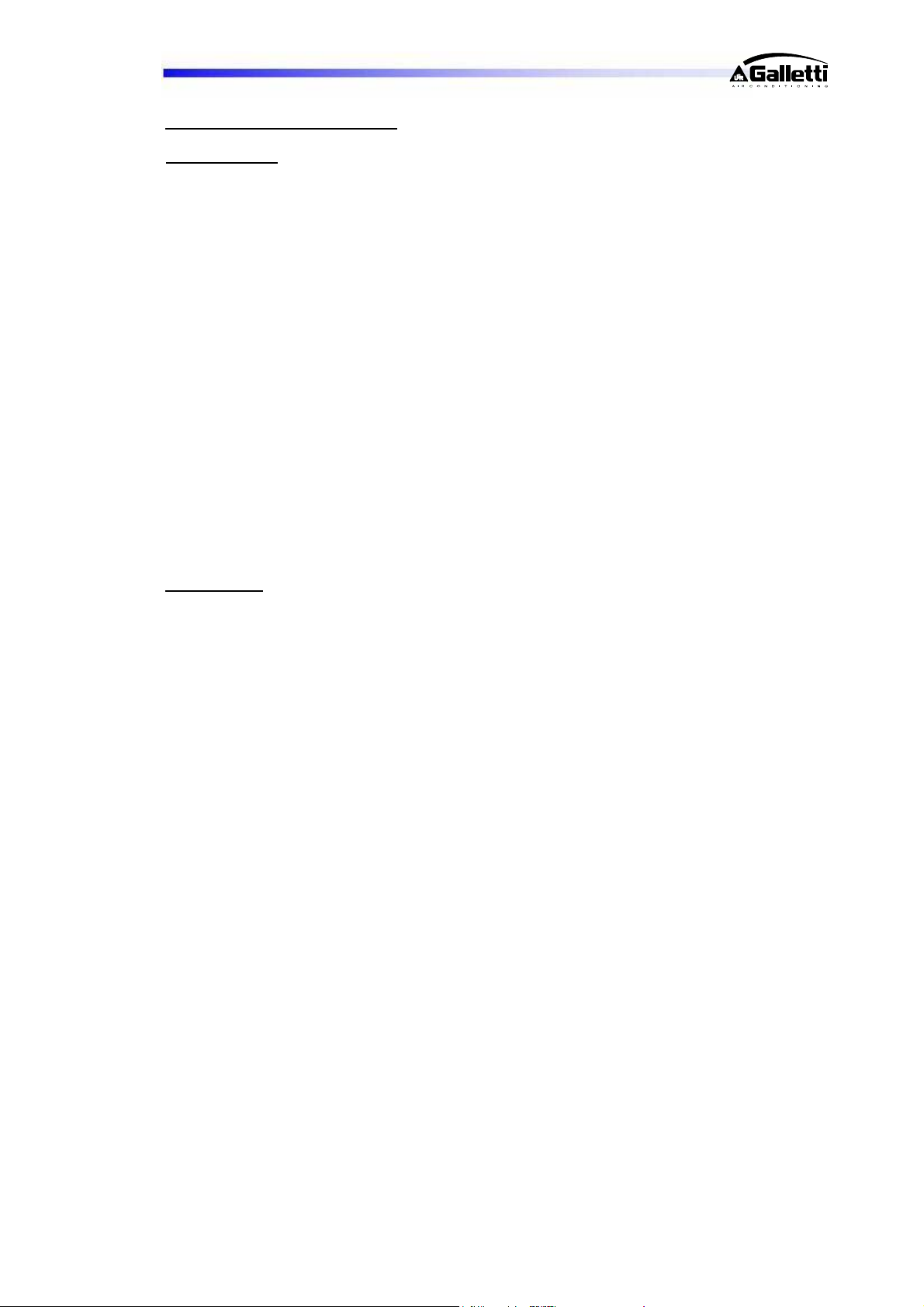
Description of operation:
The machine has 4 water connections referring to two different hydraulic circuits:
- Circuit “1” = production of cold water (summer) – hot water (winter)
- Circuit “2” = production of hot water (for example for domestic hot water)
The machine is equipped with 3 distinct heat exchangers:
- Finned pack coil (S3) with both evaporating and condensing function for heat
exchanger with the thermal source (outdoor air)
- Plate heat exchanger “S1” intended for utility circuit with evaporating function in
summer mode and condensing in winter mode
- Plate heat exchanger “S2” intended for DHW circuit condensing function (normally)
and evaporating function only during defrost cycle.
RG66006889-Rev.01 7
Page 8
LCP
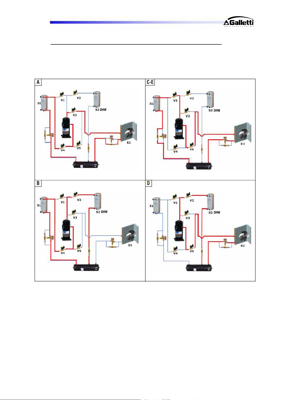
The possible operations are:
Summer Mode:
a) Cooling Only (represented on following page): the system produces cold water on
circuit "1" with the heat exchanger "S1" and the heat removed, together with the
power absorbed by the compressors, is dispersed into the outdoor air by means of
finned coils (S3) which act as condensers. Ventilation is modulated to vary the air
flow depending on condensation pressure.
b) Cooling + DHW (represented on following page): the system produces cold water
on circuit "1" with the heat exchanger "S1" and hot water on circuit "2" with the heat
exchanger "S2". The heat removed by the heat exchanger "S1", together with the
power absorbed by the compressors, is yielded to the hot water by means of the
plate heat exchanger "S2". Both circuits have the same priority, namely both will be
brought to the set-point. The finned pack heat exchangers are used to dispose
of/remove heat from the air only when requests are not equivalent. Ventilation is
normally disabled in this mode. If the finned pack heat exchanger (S3) is used,
ventilation is modulated in order to vary air flow autonomously from the two circuits
depending on the condensation/evaporation pressure.
c) DHW Only (represented on following page): the system produces hot water on
circuit "2", removing heat from outdoor air which, together with the power absorbed
by the compressors, is yielded to the water by means of the plate heat exchanger
(S2). Ventilation is modulated to vary the air flow depending on evaporation pressure.
Winter Mode:
d) Heat Only (represented on following page): the system produces hot water on
circuit "1", removing heat from outdoor air which, together with the power absorbed
by the compressors, is yielded to the water by means of the plate heat exchanger
“S1”. Ventilation is modulated to vary the air flow depending on evaporation pressure.
e) DHW Only (represented on following page): the system produces hot water on
circuit "2", removing heat from outdoor air which, together with the power absorbed
by the compressors, is yielded to the water by means of the plate heat exchanger
(S2). Ventilation is modulated to vary the air flow depending on evaporation pressure.
f) Partial heat + partial DHW: the system simultaneously produces hot water on circuit
"1" and on circuit "2" up to a maximum of 50% of both demands. If one of the two
demands exceeds 50%, priority is given to DHW, therefore to circuit "2". The heat is
removed from the outdoor air which, together with the power absorbed by the
compressors, is yielded to the utility by means of the heat exchanger "S1" and to the
DHW by means of the plate hat exchanger "S2".
Defrost cycle: the purpose is to produce heat which first heats and then melts the frost built up on the
finned coils. In order to do this, the hot water is used as a source and therefore the heat exchanger "S1"
or "S2" is used as an evaporator. The heat removed, together with the power absorbed by the
compressors, is used to defrost the finned pack exchangers (S3). Defrost logic has a low impact on the
utility since defrosting is performed separately on the 2 circuits. In this way while one circuit defrosts, the
other continues to produce heat for the utility, thus avoiding to remove heat from the system.
RG66006889-Rev.01 8
Page 9
LCP
Graphical representation of the operation cycles a-b-c-d-e described above:
RG66006889-Rev.01 9
Page 10
LCP
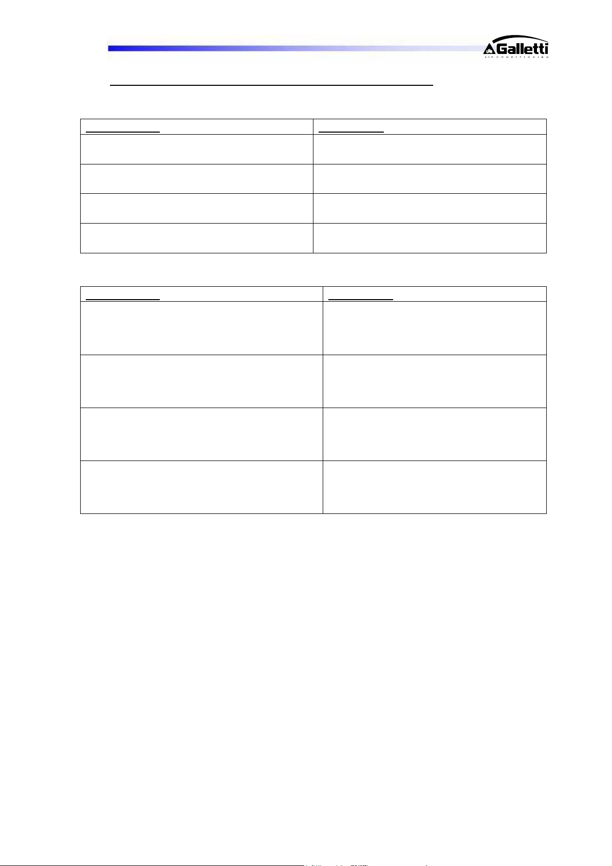
Possible operation combinations as the thermal load varies:
- Unit with 2 Compressors 2 refrigerant circuits:
Summer Mode: Winter Mode:
o 100% Cooling (1)
o 50% Cooling
o 100% Heat (4)
o 50% Heat
o 100% Cooling + 100% DHW (2)
o 50% Cooling + 50% DHW
o 50% Cooling + 100% DHW
o 100% Cooling + 50% DHW
o 100% DHW
o 50% DHW
o 50% Heat + 50% DHW
o 100% DHW (5)
o 50% DHW
- Unit with 4 Compressors 2 refrigerant circuits:
Summer Mode: Winter Mode:
o 100% Cooling (1)
o 75% Cooling
o 50% Cooling
o 25% Cooling
o 100% Heat (4)
o 75% Heat
o 50% Heat
o 25% Heat
o 100% Cooling + 100% DHW (2)
o 75% Cooling + 75% DHW
o 50% Cooling + 50% DHW
o 25% Cooling + 25% DHW
o 50% Cooling + 100% DHW
o 25% Cooling + 100% DHW
o 100% Cooling + 50% DHW
o 100% Cooling + 25% DHW
o 100% DHW
o 75% DHW
o 50% DHW
o 25% DHW
o 50% Heat + 50% DHW
o 50% Heat + 25% DHW
o 25% Heat + 50% DHW
o 25% Heat + 25% DHW
o 100% DHW (5)
o 75% DHW
o 50% DHW
o 25% DHW
(1) Summer mode for production of chilled water alone on exchanger “S1” @ 12/7°C with outdoor air 35°C.
(2) Summer mode for simultaneous production of chilled water on exchanger “S1” @ 12/7°C and hot water on
exchanger “S2” @ 40/45°C.
(3) Summer mode for production of hot water alone on exchanger “S2” @ 45/50 with outdoor air 35°C.
(4) Winter mode for production of hot water alone on exchanger “S1” @ 40/45°C with outdoor air 7°C RH90%
[possible with unit in version “H”].
(5) Winter mode for production of hot water alone on exchanger “S2” @ 40/50 with outdoor air 7°C RH90%.
RG66006889-Rev.01 10
Page 11
LCP
2 FIELD OF APPLICATION
These machines are designed to cool-heat water and solutions containing up to 35% glycol (percentage
by weight) in civil, industrial and technological air-conditioning systems.
They must be used in observance of the operating limits specified in this manual; failure to comply with
said limits will invalidate the warranties provided in the contract of sale.
3 GENERALITIES
- When installing or servicing the chiller, you must strictly follow the rules provided in this manual, comply
with the directions on the units and take all such precautions as are necessary.
- The fluids under pressure in the cooling circuit and the presence of electrical components may cause
hazardous situations during installation and maintenance work.
Therefore, only qualified personnel may perform any kind of w o rk on the unit.
- THE UNIT MUST BE STARTED UP FOR THE FIRST TIME EXCLUSIVELY BY QUALIFIED
PERSONNEL AUTHORISED BY GALLETTI S.P.A. (SEE ATTACHMENT).
- FAILURE TO COMPLY WITH THE RULES PROVIDED IN THIS MANUAL OR ANY MODIFICATION MADE
TO THE UNIT WITHOUT PRIOR AUTHORISATION WILL RESULT IN THE IMMEDIATE INVALIDATION OF
THE WARRANTY
.
Warning: Before performing any kind of work on the unit, make sure it has been
disconnected from the power supply.
RG66006889-Rev.01 11
Page 12
LCP
4 INSPECTION, CONVEYANCE, SITING
4.1 INSPECTION
On receiving the unit, check that it is perfectly intact: the chiller left the factory in perfect conditions;
immediately report any signs of damage to the carrier and note them on the Delivery Slip before
it. Check, in particular, that the fins of the finned block heat exchangers are not bent and have not
undergone impacts that may have impaired the system's tightness under pressure.
Galletti S.p.A. or its Agent must be promptly notified of the entity of the damage.
The Customer must submit a written report describing every significant sign of damage.
- commissioning report,
- wiring diagram,
- warranty certificate and list of authorised service centres,
- check the integrity of the documents accompanying the unit and of this manual.
4.2 LIFTING AND CONVEYANCE
While the unit is being unloaded and positioned, utmost care must be taken to avoid abrupt or violent
manoeuvres. The unit must be handled carefully and gently: avoid using machine components as
anchorages when lifting or moving it.
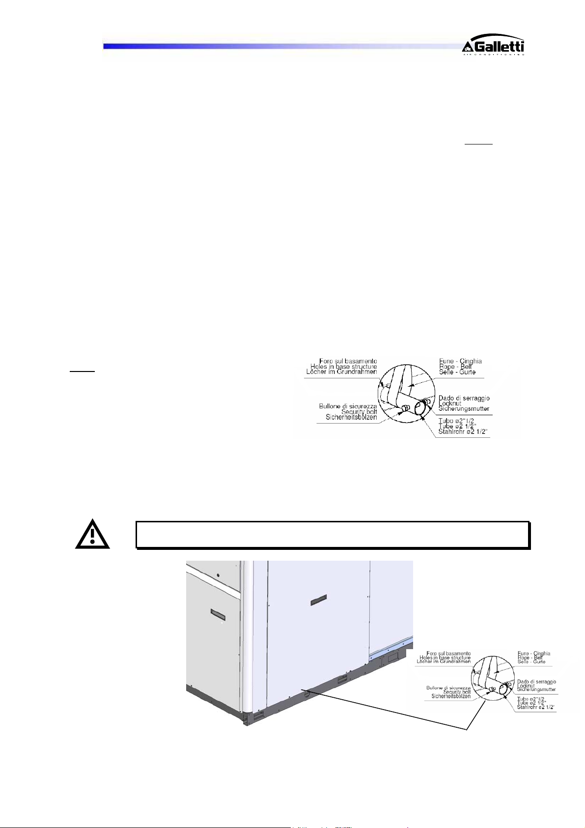
The unit should be lifted using Ø1½” GAS steel
pipes at least 3mm thick, to be inserted in the
round
holes provided on the base side members
(see fig. below) and identified by means of
stickers. The pipes, which should protrude by at
least 250-300mm on every side, must be slung
with ropes of equal length secured to the lifting
hook (provide stops at the ends of the pipes to
prevent the ropes from slipping off due to the
weight).
Use ropes or belts long enough to extend beyond the height of the unit and place spacer bars and
boards on the top of the unit to avoid damaging the sides and top of the unit itself. The rectangular holes
are provided for the attachment of vibration damping supports (optional).
Warning: In all lifting operations make sure that the unit is securely anchored in
order to prevent accidental falls or overturning.
signing
RG66006889-Rev.01 12
Page 13
LCP
4.3 UNPACKING
The packing must be carefully removed to avoid the risk of damaging the unit. Different packing materials
are used, such as wood, cardboard, nylon, etc.
It is recommended to keep them separately and deliver them to suitable waste disposal or recycling
facilities in order to minimise their environmental impact.
Warning
expansion tank packaged in the fan compartment; it must be fixed to the pump intake pipe, where a
“TEE” is fixed so as to form a tight seal, or on the tank itself. Remove the cap and screw in the expansion
tank (operation to be performed by qualified personnel), check the pre-fill pressure (0.5 - 1.0 bars-r)
before filling the water circuit and starting up the chiller.
Warning
and the water temperature range; always check the tank capacity in relation to the water content of the
system.
4.4 SITING
You should bear in mind the following aspects when choosing the best site for installing the unit and the
relative connections:
- size and origin of water pipes;
- location of power supply;
- accessibility for maintenance or repairs;
- solidity of the supporting surface;
- ventilation of the air-cooled condenser and necessary clearance;
- direction of prevalent winds: avoid positioning the unit in such a way that the prevalent winds favour the
backflow of air to the condenser coils; a speed of 8 m/s (28.8 km/h) already generates a sufficient
stagnation pressure to guarantee approx. 60% of the nominal air flow rate;
- possible reverberation of sound waves.
All models belonging to the LCP series are designed and built for outdoor installation: avoid covering
them with roof structures or positioning them near plants (even if they only partly cover the unit) which
may interfere with the regular ventilation of the unit condenser.
It is a good idea to create a base of adequate dimensions to support the unit. This precaution becomes
essential when the unit is to be sited on unstable ground (various types of soil, gardens, etc.).
It is advisable to place a rigid rubber strip between the base frame and the supporting surface.
Whenever more effective insulation is required, it is recommended to use vibrating-damping spring
supports.
In the case of installation on roofs or intermediate storeys, the unit and pipes must be insulated from
walls and ceilings by placing rigid rubber joints in between and using supports that are not rigidly
anchored to the walls.
If the unit is to be installed in proximity to private offices, bedrooms or areas where noise levels must be
kept down, it is advisable to conduct a thorough analysis of the sound field generated and verify its
compatibility with the local laws in force.
: if the unit is supplied with a pump or pumps and/or storage reservoir, you will find the
: the size of the expansion tank will depend both on the volume of water contained in the system
RG66006889-Rev.01 13
Page 14
LCP
5 INSTALLATION
5.1 INSTALLATION CLEARANCE REQUIREMENTS
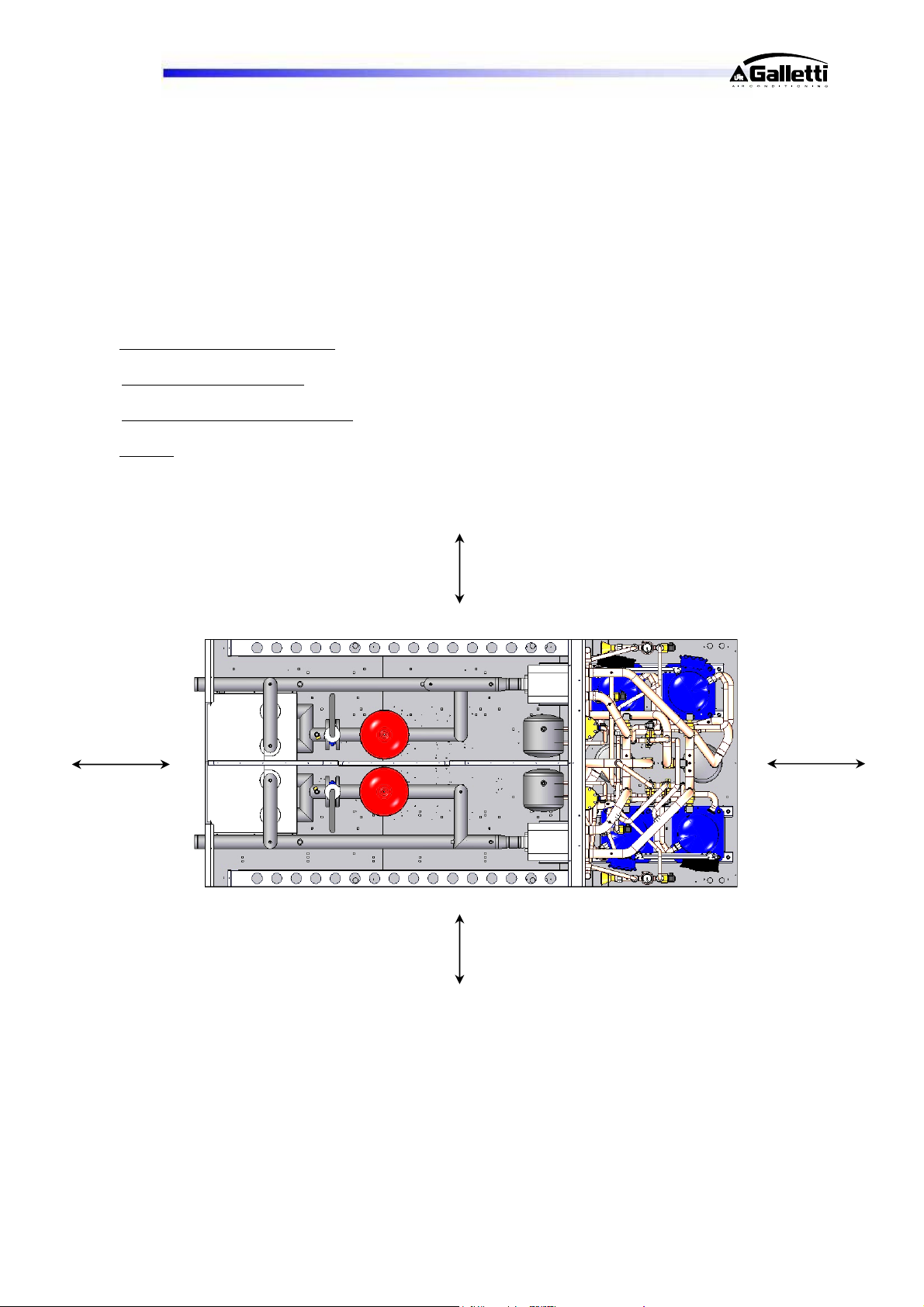
It is of fundamental importance to ensure an adequate volume of air both on the intake and outlet sides
of the finned condenser/evaporator coils; it is highly important to prevent the air delivered from being reaspirated as this may impair the performance of the unit or even cause an interruption in normal
operation. For this reason it is necessary to guarantee the following clearances (see figure on this page):
- rear side/plumbing connections: min. 1.0 metre to guarantee access to plumbing connections and/or for
any necessary maintenance on the pumps, reservoir, expansion tank and flow switch.
- electric control board side
cooling components
- finned pack heat exchanger side
compressor compartment, also from the side.
- top side
: there must be no obstacle to expulsion.
: min. 1.0 metre to guarantee access for inspection and/or maintenance of
: min. 1.5 metres to ensure proper air circulation and access to the
1.5 m
1.0 m
rear
Top view of the unit
1.5 m
1.0 m
front
RG66006889-Rev.01 14
Page 15
LCP
5.2 GENERAL GUIDELINES FOR PLUMBING CONNECTIONS
When you are getting ready to set up the water circuit for the evaporator you should follow the directions
below and in any case make sure you comply with national or local regulations (use the diagrams
included in this manual as your reference).
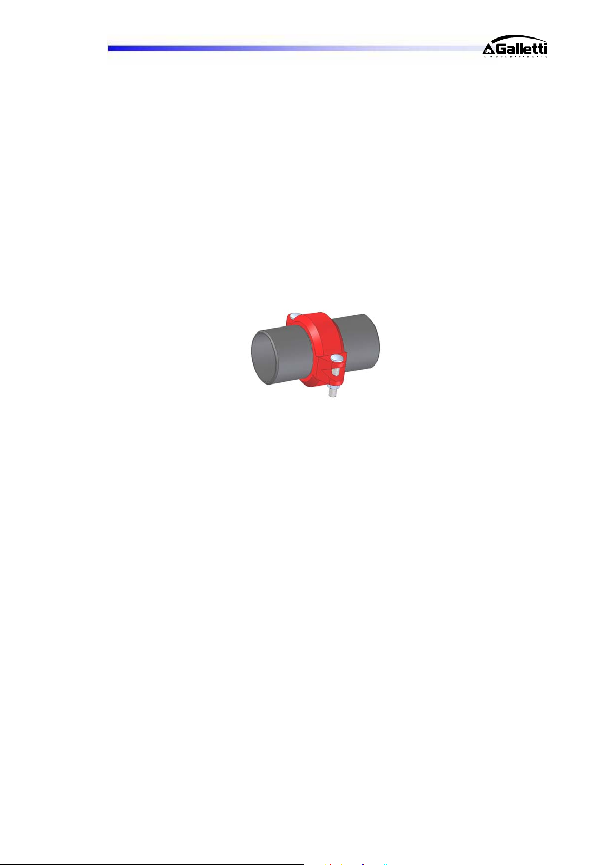
- Connect the pipes to the chiller using flexible couplings to prevent the transmission of vibrations and to
compensate for thermal expansions. These units are all configured for installation of the water inletoutlet pipes outside the unit (on the rear) and these pipes are supplied as a standard accessory at no
extra cost for the customer.
It is recommended to install the following components on the pipes:
-
pair of quick connect couplings with pipe section to be welded (optional that may be selected from
the price list). They facilitate the operations of connecting to the plumbing system, greatly speeding
up installation.
temperature and pressure indicators for routine maintenance and monitoring of the unit. Checking
the pressure on the water side will enable you to verify whether the expansion tank is working
efficiently and to promptly detect any water leaks within the equipment.
traps on incoming and outgoing pipes for temperature measurements, which can provide a direct
reading of the operating temperatures. Temperature readings can in any case be obtained from the
microprocessor installed on the unit.
regulating valves (gate valves) for isolating the unit from the water circuit.
metal mesh filter (incoming pipes), with a mesh not to exceed 1 mm, to protect the exchanger from
scale or impurities present in the pipes.
air vent valves, to be placed at the highest points of the water circuit for the purpose of bleeding air.
[The internal pipes of the unit are fitted with small air vent valves for bleeding the unit itself: this
operation may only be carried out when the unit is disconnected from the power supply -
make sure that the circuit is completely full of water, then carefully bleed out the air and check again
to make sure no air is present before starting the pump for the first time.
RG66006889-Rev.01 15
Page 16
LCP
5.3 WATER CONNECTION TO THE EVAPORATOR
It is of fundamental importance that the incoming water supply is hooked up to the
connection marked “Water Inlet”.
Otherwise the evaporator would be exposed to the risk of freezing since the antifreeze thermostat would
not be able to perform its function; moreover the reverse cycle would not be activated in the cooling
mode, resulting in additional risks of malfunctioning.
The dimensions and position of plumbing connections are shown in the dimension tables at the end of
the manual.
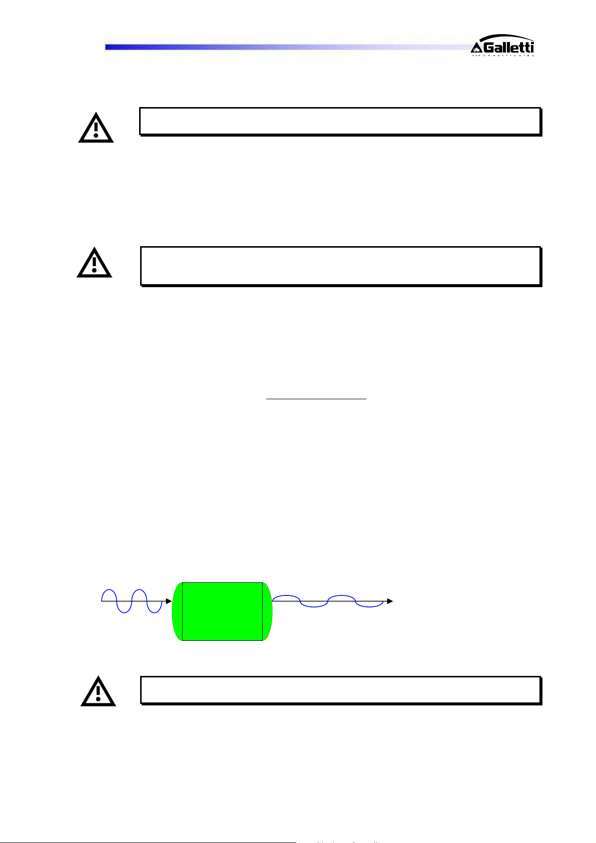
The water circuit must be set up in such a way as to guarantee that the nominal flow rate
of the water supplied to the evaporator remains constant (+/- 15%) in all operating
conditions.
The compressors often work intermittently, since the chilling requirements of the user generally do not
coincide with the output of LCP unit. In systems containing little water, where the thermal inertia of the
water is lower, it is a good idea to check that the water content in the section delivering to users satisfies
the condition below:
V
V = water content in user section [m3]
Sh = specific heat of the fluid [J/(kg/°C)]
= fluid density [kg/m3]
∆ = minimum time lapse between 2 compressor restarts [s]
∆T = allowed water T differential [°C]
Cc = Cooling capacity [W]
Ns = N° of capacity control steps
Incoming water
T
This check must be performed even though it must considered that the LCP units cannot
be configured with the tank on board.
Inertial Tank
Ts °C
Cc
Outgoing water
T
NsSh
RG66006889-Rev.01 16
Page 17
LCP
A standard feature of LCP units is a device for controlling the flow rate (vane operated
flow switch) in the water circuit in the immediate vicinity of the evaporator.
Any tampering with said device will immediately invalidate the warranty.
It is compulsory to install a metal filter with a mesh smaller less 1mm on the inlet water
pipe.
It is strongly recommended to install a safety valve in the water circuit. In the event of
serious equipment faults (e.g. fire) it will enable water to be drained from the system,
thereby preventing possible bursts. Always connect the drain outlet to a pipe with a
diameter at least as large as that of the valve opening and direct it toward an area where
the discharge of water cannot harm people. This is a standard feature of units equipped
with the optional buffer tank (optional).
Warning: When making the plumbing connections, make sure there are no open flames
in proximity to or inside the unit.
5.4 SAFETY DEVICES ON THE HIGH PRESSURE SIDE
Cooling circuit safety devices are provided on each refrigerant circuit according to the volumetric capacity
of the compressors installed, as prescribed by Directive 97/23 (PED); in particular, with respect to
equipment design, this Directive requires manufacturers to abide by the technical standard nearest to the
type of object produced; in the case of chillers designed for air conditioning or liquid cooling systems,
standard UNI EN 378-2 is taken into consideration.
According to this standard, for refrigerant mass flow rates of up to 25dm3 per circuit only one pressure
limiting device is required; beyond this limit 2 must be applied. Practically speaking, these are safety
pressure switches designed to protect the cooling circuit in a cascade fashion.
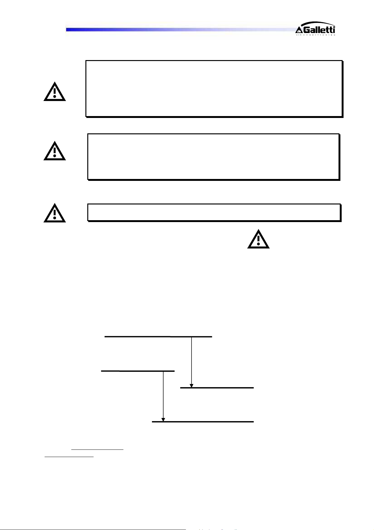
What is meant by cascade protection is illustrated in the figure:
Pressure switch 1
Cut out
Pressure switch 2
…where pressure switch 1
pressure switch 2
RG66006889-Rev.01 17
will have the setting = PS x 0.9 in accordance with the reference technical standard.
Cut out
Cut in
Cut in
is set at the “PS” (maximum admissible pressure) of the system, while
Page 18
LCP
6 ELECTRICAL CONNECTIONS
6.1 GENERALITIES
Before carrying out any job on electrical parts, make sure the power supply is
disconnected.
Check that the mains electricity supply is compatible with the specifications (voltage, number of phases,
frequency) shown on the unit rating plate.
The power connection is made by means of a three-core cable plus neutral and earth cable or singlecore cables (one per phase) + earth according to the minimum cross section sizes specified in the wiring
diagram, which is an integral part of the documentation accompanying the chiller; the diagram code also
appears on the rating plate inside the compressor compartment.
The size of the cable and line protections must conform to the specifications provided in
the wiring diagram.
The supply voltage may not undergo fluctuations exceeding ±5% and the unbalance between phases
must always be below 2%.
The above operating conditions must always be complied with: failure to ensure said
conditions will result in the immediate invalidation of the warranty.
The electrical connections must be made in accordance with the information shown in the wiring diagram
provided with the unit and current regulations.
Electrical connections and preliminary checks:
Put on the main switch, turn the ½-turn locking screws of the electric enclosure and open it.
Introduce the power cable 400/3/50+N through the hole provided on the left side of the unit (after first
removing and making a hole in the aluminium square based on the diameter of the electric cable) and
secure it with a cable gland.
Connect the power supply and earthing wire to the terminals of the main switch.
Open the fuse carriers F1 and F2 (or Q1 and Q2 for the motor overload cutouts) of the compressors (F1-
F2-F3-F4 for the fuses or Q1-Q2-Q3-Q4 for the overload cutouts in the case of LCP 4 compressor models)
to prevent them from starting up in the wrong direction in the event of an incorrect phase sequence.
Switch on the power supply by turning the main switch (QS) to ON.
Verify whether the phase sequence R-S-T is correct by checking, on the phase sequence relay situated in
the middle of the electric control board, that the green power on LED and yellow LED indicating the correct
sequence both light up; if this does not occur, disconnect the chiller power supply from the external
distribution panel and swap over two phases; then repeat the operation. IN NO CASE SHOULD YOU
TAMPER WITH THE WIRING DOWNSTREAM FROM THE MAIN SWITCH since this may alter the correct
sequence of other devices, e.g. pump(s).
Close the fuse carriers F1 and F2 of the compressors (F1-F2-F3-F4 in the case of LCP 4 compressor
models).
Close the electric enclosure and lock it by means of the ½- turn locks.
An earth connection is required by law. The installer must connect the earthing wire using the earthing
terminal situated on the electric control board (yellow and green wire).
The power supply to the control circuit is shunted from the power line through an insulating transformer
situated on the electric control board.
The control circuit is protected by suitable fuses.
A standard
necessary to assure that the chiller is completely functional before enabling a compressor start-up.
RG66006889-Rev.01 18
feature of all units is a phase sequence relay that verifies the correct phase sequence; this is
Page 19
LCP
6.2 ELECTRICAL CONNECTIONS OF WATER VANE OPERATED FLOW SWITCH
Available for all LCP units is an additional vane operating flow switch installed in series with the water
and electrical circuits and wired in the unit configuration.
6.3 ELECTRIC CONNECTIONS OF THE CIRCULATION PUMP
If selected on ordering, it/they is/are supplied pre-wired with all LCP units. For dual pump kits, whether
set up according to an “AND” or “OR” logic, rotation is controlled on a time basis and triggered in the
event of a fault.
Possible pump-tank configurations:
- Built-in tank available only
- 2 pumps which can be configured on demand can be installed on the buffer tank:
1 utility side pump + 1 DHW side pump
2 utility side pumps with “OR” (Standby rotation) or “AND” (parallel) logic
2 DHW side pumps with “OR” (Standby rotation) or “AND” (parallel) logic
- Two external pumps can be managed from the electrical control board with "OR"
(Standby rotation) or “AND” (parallel) logic with a very low voltage (24 Vac) control by
an insulating transformer or clean contacts.
- If there is not buffer tank, the dual pump can be installed on board either on the utility
side or on the DHW side with "OR" (Standby rotation) or “AND” (parallel) logic.
The pump/s must be started before the chiller and stopped after the latter (minimum
recommended delay: 60 seconds). If included as an option, this function is already
performed by the microprocessor on the unit.
6.4 REMOTE CONTROLS
If you wish to include a remote control for switching the unit on and off, you must remove the jumper
between the contacts indicated in the wiring diagram and connect the remote ON/OFF control to the
terminals themselves [see annexed wiring diagram].
All remote controls work with a very low voltage (24 Vac) supplied by the insulating
transformer on the electric control board.
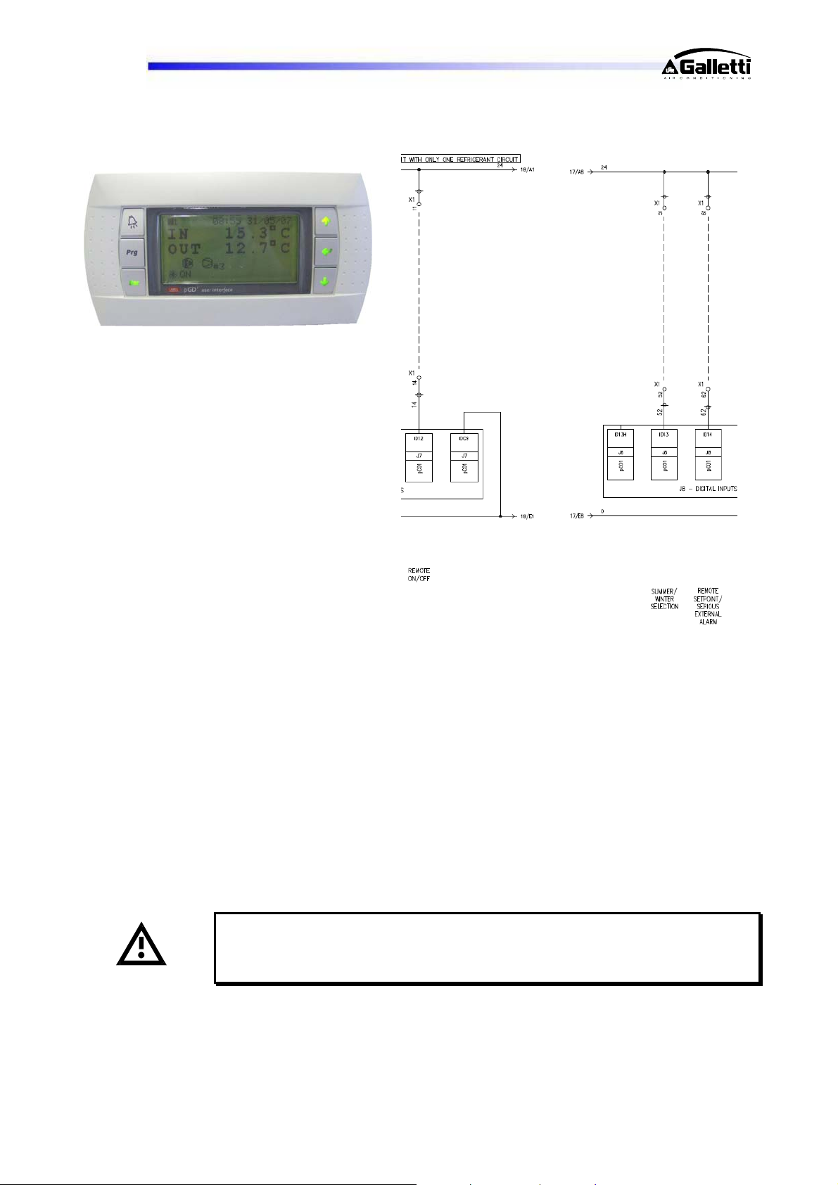
6.5 REMOTE SUMMER-WINTER SWITCHING
If you wish to include a remote control for switching the unit between the summer and winter operating
modes, you must remove the jumper between the contacts indicated in the wiring diagram and connect
the remote switching control to the terminals themselves [see annexed wiring diagram]. The switching
modes vary according to whether the microprocessor control is of the basic or advanced type: detailed
instructions are provided below (see extract of corresponding wiring diagram) and in the microprocessor
user manual, an integral part of the documentation provided.
on utility side (system)
RG66006889-Rev.01 19
Page 20
LCP
pCO
7 STARTING UP
7.1 PRELIMINARY CHECKS
- Check that all the valves in the cooling circuit are open (liquid line).
- Check that the electrical connections have been made properly and that all the terminals are
securely tightened. This check should also be included in a periodic six-month inspection.
- Check that the voltage at the RST terminals is 400 V ± 5% and make sure the yellow indicator light
of the phase sequence relay is on. The phase sequence relay is positioned in the middle right part of
the electric control board; if the sequence is not duly observed, it will not enable the machine to start.
- Make sure there are no refrigerant leaks that may have been caused by accidental impacts during
transport and/or installation.
- Check the power supply to the crankcase heating elements, where present.
The heating elements must be turned on at least 5-10 minutes before the unit is
started. This function is carried out automatically when the main switch is off. Their
function is to raise the T of the oil in the sump and limit the quantity of refrigerant
dissolved in it.
To verify whether the heating elements are working properly, check the lower part of the compressors:
it should be warm or in any case at a temperature 10 -15°C higher than the ambient temperature.
RG66006889-Rev.01 20
Page 21
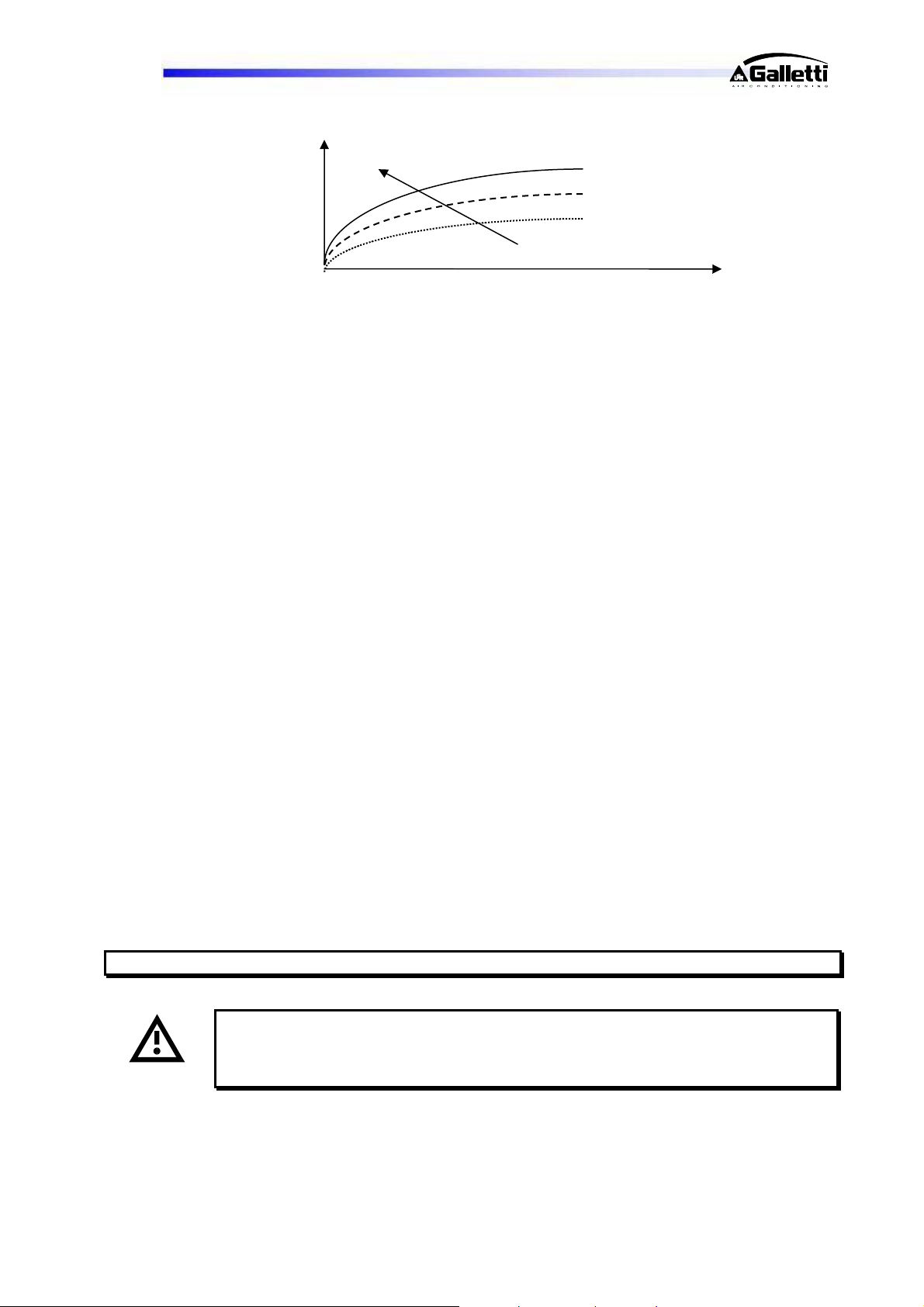
LCP
The diagram above illustrates a specific property [Charles’ Law] of gases, which are more soluble in
liquids as the pressure increases but less soluble as the temperature increases: if the oil is held at a
constant pressure: an increase in temperature will significantly reduce the amount of refrigerant
dissolved in it, thus ensuring that the lubricating function desired is maintained. At the same time it
should be observed that a slight foaming [1-5 mm] of the oil at start up (pressure drop => decrease in %
of solubility] is normal and will not compromise the system's reliability.
- Check that the plumbing connections have been properly made according to the indications given on
the plates to be found on the unit itself (proper inlet and outlet connections).
- Make sure that the water circuit is duly bled to completely eliminate the presence of air: fill the circuit
gradually and open the air vent valves on the top part, which the installer should have set in place.
7.2 STARTING OPERATION
Before starting the chiller, turn the main switch off, select the operating mode desired from the control
panel [red button = heating, green button = cooling] and press the "ON" button on the control panel.
The unit will start up if enabled:
- by the safety devices of the water circulation pump/s
- by the flow switch (or differential pressure switch)
- by the T sensor measuring the temperature of the water returning from the system [chiller inlet]
- and no alarms have been triggered
Starting up:
Check that all external cocks of the water circuit are open and water flows properly (the flow alarm should
not be triggered).
Put the main switch in the ON position.
Check the water temperature differential (12-7°C to be detected by means of a thermometer on the inlet
and outlet water pipes of the unit).
Check that there are no leaks on the refrigerant side and water side.
Using all the screws supplied, close the unit.
If the unit fails to start up, check whether the set point has been set on the desired values.
Pressure
in
crankcase
Oil T
% of R410A dissolved in oil
o The pump will start immediately.
o After 60 seconds the compressor will start.
You should not disconnect the unit from the power supply during periods when it is
inoperative but only when it is to be taken out of service for a prolonged period (e.g. at
the end of the season). To turn off the unit temporarily, follow the directions provided in
the section "Stopping the Unit".
RG66006889-Rev.01 21
Page 22
LCP
7.3 CHECKS DURING OPERATION
- Check the phase sequence relay on the electrical control board to verify whether the phases occur in
the correct sequence: if they do not, disconnect the unit from power supply and reverse two phases at
the unit input
render the warranty null and void.
- Check that the temperature of the water entering the evaporator (returning from the system) is close to
the setpoint value entered. How long it will take to reach full operating capacity depends on the starting
conditions, system size and load conditions.
7.4 CHECKING THE REFRIGERANT LEVEL
- After a few hours of operation, check whether the liquid level indicator has a green crown: a yellow
colour indicates the presence of humidity in the circuit. In such a case the circuit must be dehumidified
by qualified personnel.
- Large quantities of bubbles should not appear through the liquid level indicator. A constant passage of
numerous bubbles may indicate that the refrigerant level is low and needs to be topped up.
- A few minutes after the compressors have started up, check that the end-of-condensation
temperature shown on the pressure gauge (refer to the pressure gauge scale for the refrigerant
R410A, marked with the initials D.P. - Dew Point) is about 16-22 °C (depending on the type of unit
and charging conditions) higher than the temperature of the air entering the condenser with the fans
running at top speed.
- Also check that the end-of-evaporation temperature shown on the pressure gauge (refer to the
pressure gauge scale for the refrigerant R410A, marked with the initials D.P. - Dew Point) is about
3.5 - 5.0 °C lower than the temperature of the water leaving the evaporator.
- Make sure the superheating of the refrigerant fluid is limited to between 5 and 8 °C. To this end:
1) read the temperature indicated by a contact thermometer placed on the compressor intake pipe;
2) read the temperature indicated on the scale of a pressure gauge likewise connected to the intake
side; refer to the pressure gauge scale for the refrigerant R410A, marked with the initials D.P. (Dew
Point).
The degree of superheating is given by the difference between the temperatures thus determined.
- Make sure the subcooling of the refrigerant fluid is limited to between 4 and 6. To this end:
1) read the temperature indicated by a contact thermometer placed on the condenser outlet pipe;
2) read the temperature indicated on the scale of a pressure gauge connected to the liquid inlet at the
condenser outlet; refer to the pressure gauge scale for the refrigerant R410A, marked with the
initials B.P. (Bubble Point).
The degree of subcooling is given by the difference between the temperatures thus determined.
RG66006889-Rev.01 22
. Never attempt to modify internal electrical connections: any undue modifications will
All the three-phase devices on the unit, compressor, water pump and fans (some
versions) have a set direction of rotation and were harmonized in the factory.
Warning: all LCP units are charged with HFC R410A: any top-ups must be made by
specialised personnel using the same type of refrigerant, exclusively in the liquid phase.
Page 23
LCP
Warning: the refrigerant R410A requires “POE” polyolester oil of a type approved by the
compressor manufacturer.
For no reason should a mineral oil be introduced into the oil circuit.
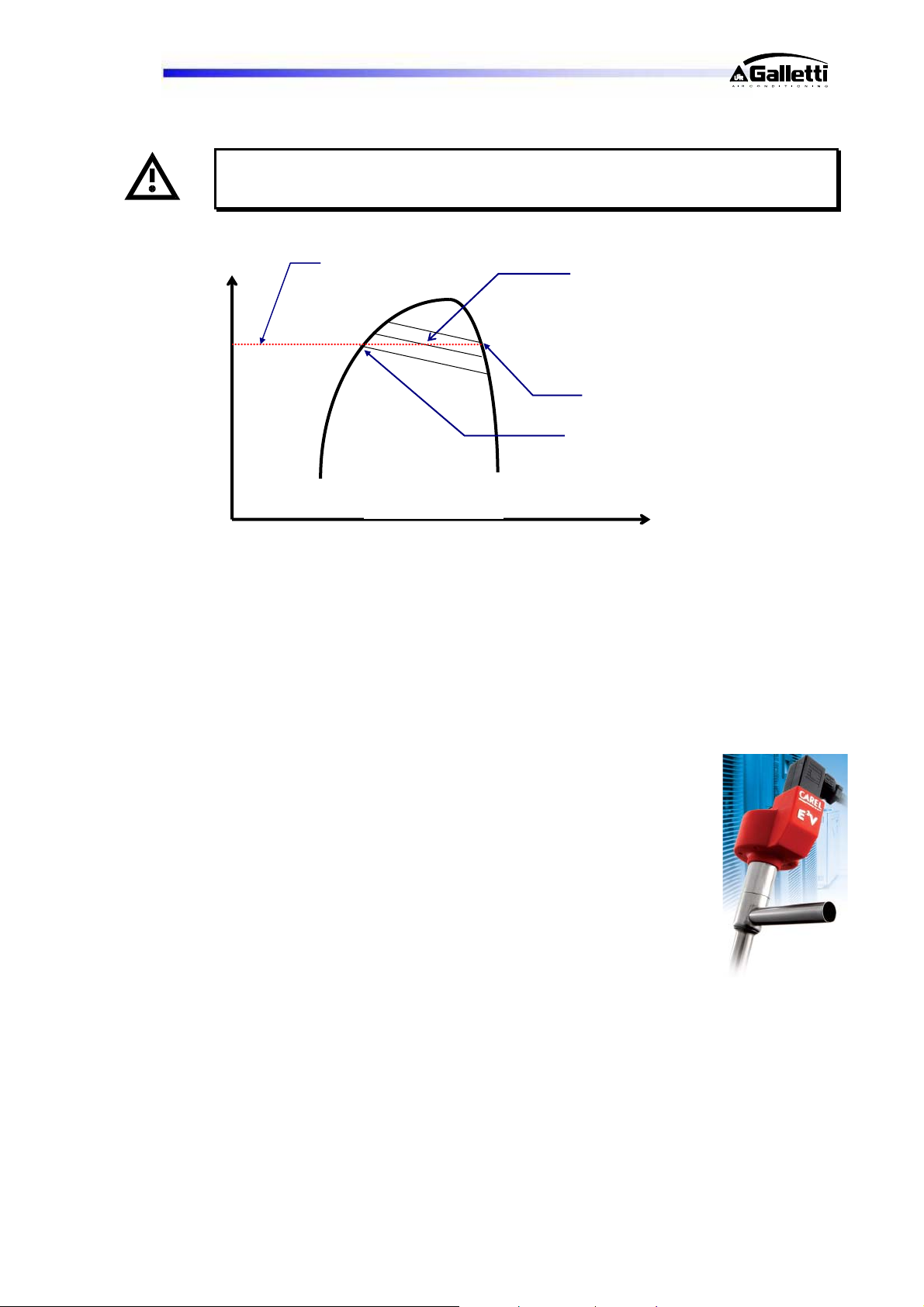
P
- The difference between the Dew Point and Bubble Point is known as “GLIDE” and this is a
characteristic property of refrigerant mixtures. If pure fluids are used, the phase change
occurs at a constant T and thus the glide is equal to zero. If HFC R410A [
R32/R125
] is used, the glide will be negligible (0.2°C) and the fluid can be considered like a
pure fluid.
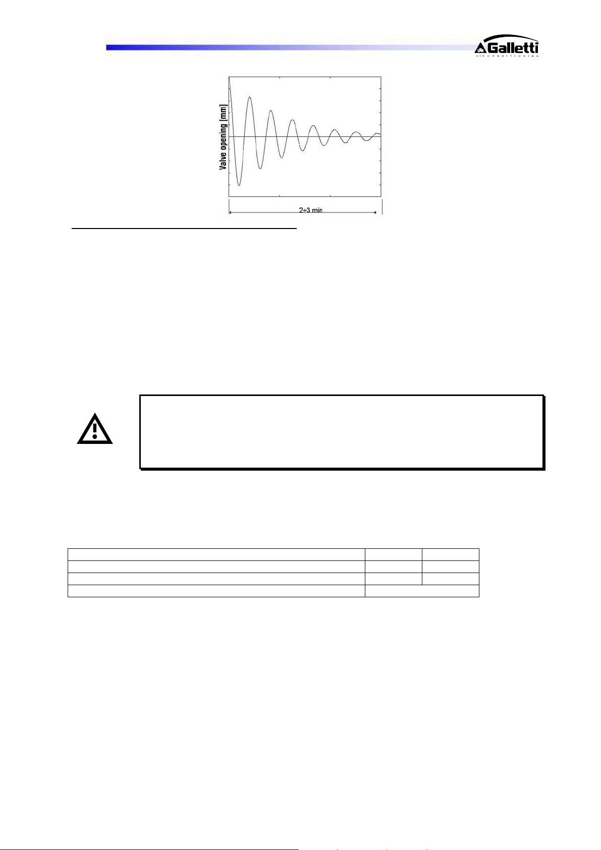
7.5 EXPANSION VALVE (OPTIONAL)
An electronically controlled expansion valve is installed as a
standard feature on all LCP units. If correctly parameterised and
controlled by the software, this device has the ability to render the
operation of the cooling circuit highly efficient and this will have the
ultimate effect of decreasing the power intake of the system
when a sudden change occurs in the thermal load. With a traditional
expansion valve there is a transient time of 2 to 3 minutes before a
condition of equilibrium is reached.
Example:
A compressor switches off
The evaporation temperature increases
Superheating decreases
The valve closes
The refrigerant flow rate decreases
The cooling capacity decreases
The evaporation temperature decreases
…and so on...
Compressor
discharge
real P
R410A
Average T
(T1+T2)/2
T1 (start of condensation)
T2 (end of condensation)
Enthalpy h
50%-50% blend of
RG66006889-Rev.01 23
Page 24
LCP
Proactive action of an Electronic Expansion Valve:
In the event of a compressor on/off request:
The electronic driver pre-positions the valve at a point very near the final equilibrium point
A status of equilibrium is quickly reached with small adjustments
The electronic expansion valve becomes an active, rather than passive, component within
the system
The transient time is greatly reduced
Overall the system is more efficient, with higher EERs and therefore greater savings
7.6 STOPPING THE UNIT
The unit can be stopped by pressing the "OFF" button on the front panel, by turning off the main switch,
or via the specific commands on the LCD user interface.
Warning: you should avoid stopping the unit using the main switch. The latter device
should be used to disconnect the unit from the electricity supply when there is no
passage of current, i.e. when the unit is already turned OFF.
Moreover, if you completely disconnect the unit from the electricity supply, the crankcase
heating elements will receive no power, thereby jeopardising the integrity of the
compressor the next time the unit is started.
8 OPERATING LIMITS
Operating limits of LCP chillers in relation to the outlet water temperature (in brackets, in cooling mode)
and outdoor air temperature:
Min. Max.
Evaporator outlet water temperature [°C]: 5 (30) 12 (45)
External air temperature [°C]: -10 45
Maximum temperature of Domestic How Water [°C] 50
8.1 WATER FLOW TO EVAPORATOR
The nominal flow rate is based on a temperature differential of 5° C between inlet and outlet water, in
relation to the cooling capacity provided at the nominal water (12/7 °C) and air (35°C) temperatures.
The maximum allowed flow rate is associated with a temperature differential of 3 °C. Higher flow rates,
though admissible, cause pointless, high drops in pressure.
The minimum allowed flow rate is associated with a temperature differential of 8 °C or a minimum
pressure drop of 10 kPa: lower flow rates cause a reduction in heat exchange coefficients and
excessively low evaporation temperatures, which may trigger the safety devices and cause the unit to
stop.
RG66006889-Rev.01 24
Page 25
LCP
8.2 CHILLED WATER TEMPERATURE
The minimum temperature of the water leaving the evaporator is 5°C: lower temperatures are possible,
but for such applications the Manufacturer should be consulted at the time the order is placed.
The maximum temperature of the water entering the evaporator is 20°C. To allow higher temperatures
specific equipment solutions must be adapted (split circuits, three-way valves, bypasses, storage
reservoirs): applications outside the specified limits may be authorised by Galletti S.p.A. subject to
verification and subsequent authorisation in writing.
8.3 OUTDOOR AIR TEMPERATURE
The units are designed and built to work with outdoor air temperatures ranging from -10 (with
condensation control) to 45 °C. Applications outside the specified limits may be authorised by Galletti
S.p.A. subject to verification and subsequent authorisation in writing. On request, the units may be
equipped with an electric heating element for heating the evaporator in cases where the unit is exposed
to severe temperatures during wintertime shutdown periods.
The heating element is activated whenever the temperature of the water leaving the evaporator falls
below the temperature set on the antifreeze probe.
8.4 OPERATION WITH WATER AT LOW TEMPERATURES
The standard units are not designed to work with chilled water temperatures below 5°C at
the evaporator outlet. In order to work below this limit, the unit requires specific technical
adjustments: in such cases contact the Manufacturer.
9 SETTING OPERATING PARAMETERS
9.1 GENERALITIES
All the control devices are set and tested in the factory before the unit is dispatched. However, after the
unit has been in service for a reasonable period of time you can perform a check on the operating and
safety devices. The settings are shown in Tables I and II.
The control devices may be serviced SOLELY BY QUALIFIED TECHNICIANS:
incorrect settings may cause serious damage to the unit and injury to persons.
Many of the operating parameters and system settings are configured by means of the microprocessor
control and are protected by passwords.
TABLE I – SETTING OF CONTROL DEVICES
CONTROL DEVICE
Service thermostat [HS-HL-PS-PL] °C 12 4
- LCP SERIES
SET POINT DIFFERENTIAL
Service thermostat [HS-HL-PS-PL] °C 40 4
RG66006889-Rev.01 25
Page 26
LCP
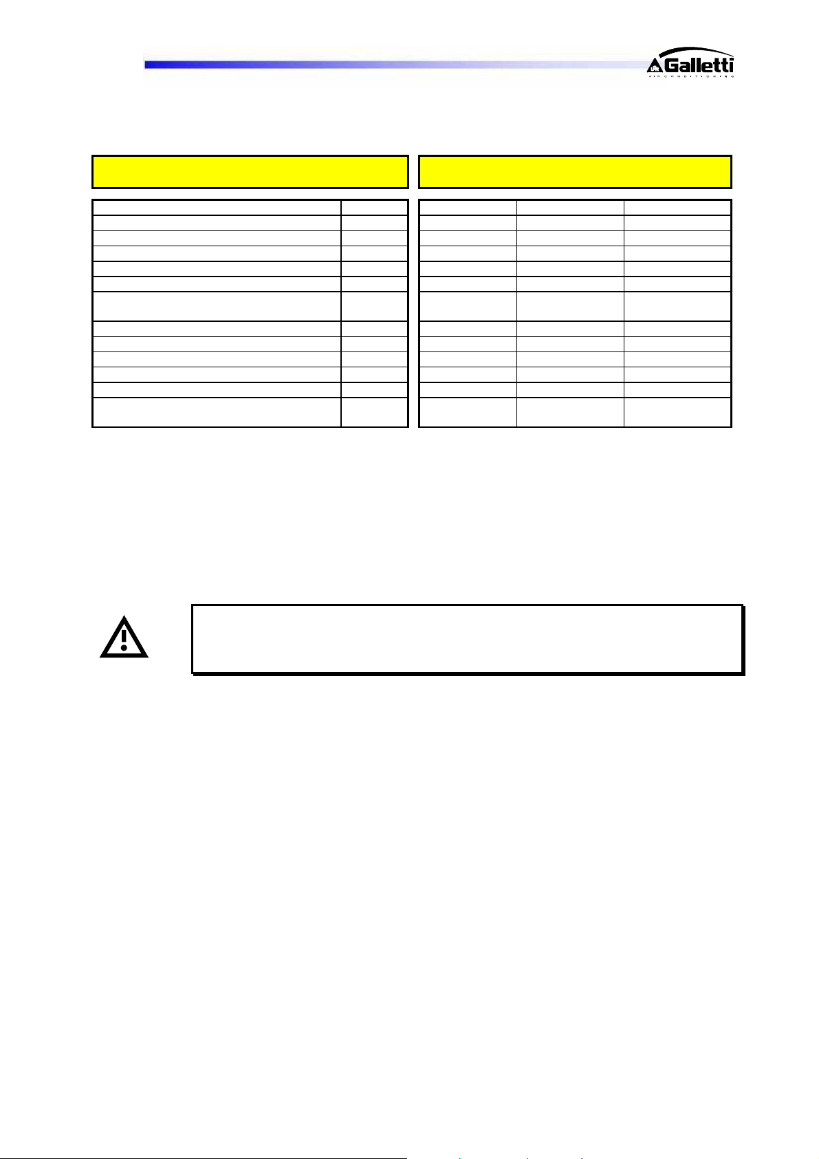
TABLE II – SETTING OF SAFETY - CONTROL DEVICES
Antifreeze thermostat °C +4 1 Automatic
Safety maximum pressure switch bar 45 -13,5 Manual
Safety maximum pressure switch bar 40,5 -12,2 Manual
High pressure relief valve bar - - Minimum pressure switch bar 1,5 +1,0 Automatic
Modulating condensation control device bar 18 10
Time lapse between two starts of the same
compressor
Delay in flow switch alarm s 20 - Delay in low pressure alarm s 1 - Pump rotation [optional] h 6 - End-of-defrost pressure bar 29 - Maximum defrost time s 360 - Minimum time lapse between two
defrosting operations
9.2 MAXIMUM PRESSURE SWITCH
The high pressure switch is of the manually reset type and classifiable as category IV under EEC 97/23.
It directly stops the compressor when the discharge pressure exceeds the set value (see section 5.4).
To verify its efficiency, while the compressors are running, close off the passage of air into the
condensers and check by referring to the compressor outlet pressure gauge (previously installed)
whether the pressure switch trips (i.e. the compressors stop) when the set value is reached.
The high pressure switch must be manually reset; this is possible only when the pressure falls below the
set differential (see Table II).
9.3 MINIMUM PRESSURE SWITCH
The low pressure switch stops the compressor when the intake pressure falls below the set value for
more than 60 seconds.
The switch is automatically reset when the pressure rises above the set differential (see Table II);
however, the unit will not resume operation until the alarm memory on the microprocessor control is
cleared.
9.4 SERVICE THERMOSTAT
The function of this device is to start and stop the compressors according to the demand for chilled
water, as determined by a sensor placed at the evaporator inlet [water returning from the circuit].
This device is a function included in the microprocessor control and works with a proportional band width
that may be set as desired.
- LCP SERIES
CONTROL DEVICE ACTIVATION DIFFERENTIAL RESETTING
s 450 - -
s 1800 - -
Warning: during this operation, if the safety device fails to trip, the second cascadeconnected pressure switch will step in to shut down the unit; in any event, however, you
should be ready to shut off the unit as directed in the section "Stopping the Unit" – see
also section 5.4.
RG66006889-Rev.01 26
Page 27
LCP
9.5 ANTIFREEZE THERMOSTAT
The antifreeze sensor situated at the evaporator outlet detects the presence of excessively low
temperatures and stops the unit. Together with the flow switch and low pressure switch, this device
protects the evaporator from the risk of freezing as a result of faults in the water circuit.
This device is a function included in the microprocessor control.
9.6 ANTI-RECYCLE TIMER
The function of the timer is to prevent excessively frequent compressor starts and stops.
This device is a function included in the microprocessor control.
It imposes a minimum time lapse of 300 seconds between two successive starts.
Never attempt to change the delay set in the factory: wrong settings could cause serious
damage to the unit.
9.7 OIL DIFFERENTIAL PRESSURE SWITCH
LCP units are equipped with spinning scroll compressors; these compressors do not have a lubricant
pump and therefore no oil differential pressure switch is provided.
10 ROUTINE MAINTENANCE AND CHECKS
10.1 WARNINGS
All the operations described in this chapter MUST ALWAYS BE PERFORMED BY
QUALIFIED PERSONNEL.
Before carrying out any work on the unit or accessing internal parts, make sure
you have disconnected it from the mains electricity supply.
The upper part and outlet pipe of the compressor may reach temperatures as high
as 110°C. Be especially careful when working in the surrounding area while the
unit is running.
Be especially careful when working in proximity to finned coils since the 0.11 mmthick aluminium fins can cause superficial injuries due to cuts.
After completing maintenance jobs, always replace the panels enclosing the units
and secure them with the fastening screws provided.
RG66006889-Rev.01 27
Page 28
LCP
10.2 GENERALITIES
It is a good idea to carry out periodic checks to ensure that the unit is working properly:
Check the efficiency of all the control and safety devices as previously described.
Check the terminals on the electric control board and compressor terminal boards to ensure that they
are securely tightened. The movable and fixed contacts of the contactors must be periodically
cleaned and replaced whenever they show signs of deterioration.
Check the refrigerant level by means of the liquid level indicator (every 6 months).
Check the oil levels through the windows provided on the compressor crankcases (every 6 months).
Check the water circuit for leaks (every 6 months).
Check the filling of the water circuit, bleeding air from the circuit by means of the valves situated in
the highest points.
Check the efficiency of the flow switch or differential pressure switch
Check the heating elements, where present, of the compressor crankcases.
Clean the metal mesh filters mounted externally on the water pipes.
Check the humidity indicator on the liquid level indicator (green=dry, yellow=humid); if the indicator is
not green as shown on the indicator sticker, replace the filter (every 6 months).
Check that the noise emissions of the unit are regular (every 6 months) and more specifically that no
vibrations and/or knocking can be detected.
Galletti S.p.A.. is not responsible for inexact translations of the manual in languages
other than English.
10.3 REPAIRING THE COOLING CIRCUIT
Warning: while performing repairs on the cooling circuit or maintenance work on
the compressors, make sure the circuit is left open for as little time as possible.
Even if briefly exposed to air, ester oils tend to absorb large amounts of humidity,
which results in the formation of weak acids.
If the cooling circuit has undergone any repairs, the following operations must be carried out:
- tightness test;
- emptying and drying of the cooling circuit;
- charging with refrigerant.
If the system has to be drained, always recover the refrigerant present in the circuit using
suitable equipment; the refrigerant should be handled exclusively in the liquid phase.
10.4 TIGHTNESS TEST
Fill the circuit with anhydrous nitrogen supplied from a tank with a pressure-reducing valve until the
pressure rises to 10 bar.
During the pressurisation phase, do not exceed the pressure setting of the safety valves;
otherwise you will cause the latter to open.
The presence of any leaks must be determined using special leak detectors. Should any leaks be
detected during the test, empty out the circuit before repairing the leaks with suitable alloys.
RG66006889-Rev.01 28
Page 29
LCP
Do not use oxygen in the place of nitrogen as a test agent, since this could cause a risk
of explosion as well as the certainty of extensive oxidisation in high-temperature areas.
10.5 HARD VACUUM AND DRYING OF THE COOLING CIRCUIT
To achieve a hard vacuum in the cooling circuit it is necessary to use a pump capable of generating a
high degree of vacuum, i.e. 15 Pa of absolute pressure.
If there is no suitable vacuum pump available, or whenever the circuit has remained open for long periods
of time, you are strongly recommended to adopt the triple evacuation method. This method is also
recommended when there is a presence of humidity within the circuit.
The vacuum pump should be connected to the inlets.
The procedure to be carried out is as follows:
- Evacuate the circuit until you reach an absolute pressure of at least 35 Pa. At this point inject nitrogen
into the circuit until you reach a relative pressure of about 1 bar.
- Repeat the step described above.
- Carry out the step described above for the third time, but in this case attempting to reach the hardest
vacuum possible.
Using this procedure you can easily remove up to 99% of pollutants.
10.6 CHARGING WITH R410A REFRIGERANT
- Connect the tank of refrigerant gas to the male 1/4 SAE inlet situated on the liquid line after discharging
a little gas to eliminate air in the connection pipe.
- Carry out the charging operation with the refrigerant in liquid form until you reach 75% of the total
charge.
- Then connect to the inlet on the intake line and complete the charging process with the refrigerant in
liquid form until no more bubbles can be seen on the liquid level indicator and the operating
parameters specified in the section "Checking the refrigerant level" have been reached.
Since R410A is a binary blend of R32 and R125, it is advisable to charge with refrigerant
in the liquid phase to ensure the correct percentage of the 2 components.
Charge through the charging inlet provided between the expansion valve and evaporator
inlet.
A unit that was originally charged with R410A in the factory cannot be charged with other
refrigerants.
RG66006889-Rev.01 29
Page 30
LCP
10.7 ENVIRONMENTAL PROTECTION
The law implementing the regulations [reg. EEC 2037/00] which govern the use of ozone-depleting
substances and greenhouse gases bans the dispersal of refrigerant gases in the environment and
requires whoever is in their possession to recover them and, at the end of their useful life, either to return
them to the dealer or take them to a suitable waste disposal facility.
The refrigerant HFC R410A is not harmful to the ozone layer but is included among the substances
responsible for the greenhouse effect and thus falls within the scope of the aforesaid regulations.
Therefore, special care should be taken when carrying out maintenance work to
minimise refrigerant leaks.
11 RETIRING THE UNIT
When the unit has reached the end of its working life and needs to removed and replaced, a series of
operations should be carried out:
- the refrigerant gas it contains should be recovered by specialised personnel and sent to a waste
collection facility;
- the lubricating oil in the compressors should also be recovered and sent to a waste collection facility;
- if they cannot be reused, the framework and components should be scrapped and separated according
to the type of material: this applies especially for the considerable quantities of copper and aluminium
present in the unit.
This will make the job of waste collection, disposal and recycling facilities easier and minimise the
environmental impact of such processes.
RG66006889-Rev.01 30
Page 31
LCP
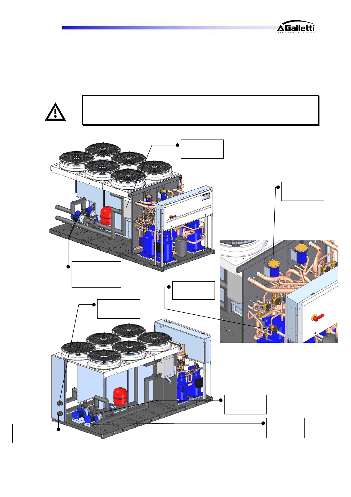
12 TROUBLESHOOTING
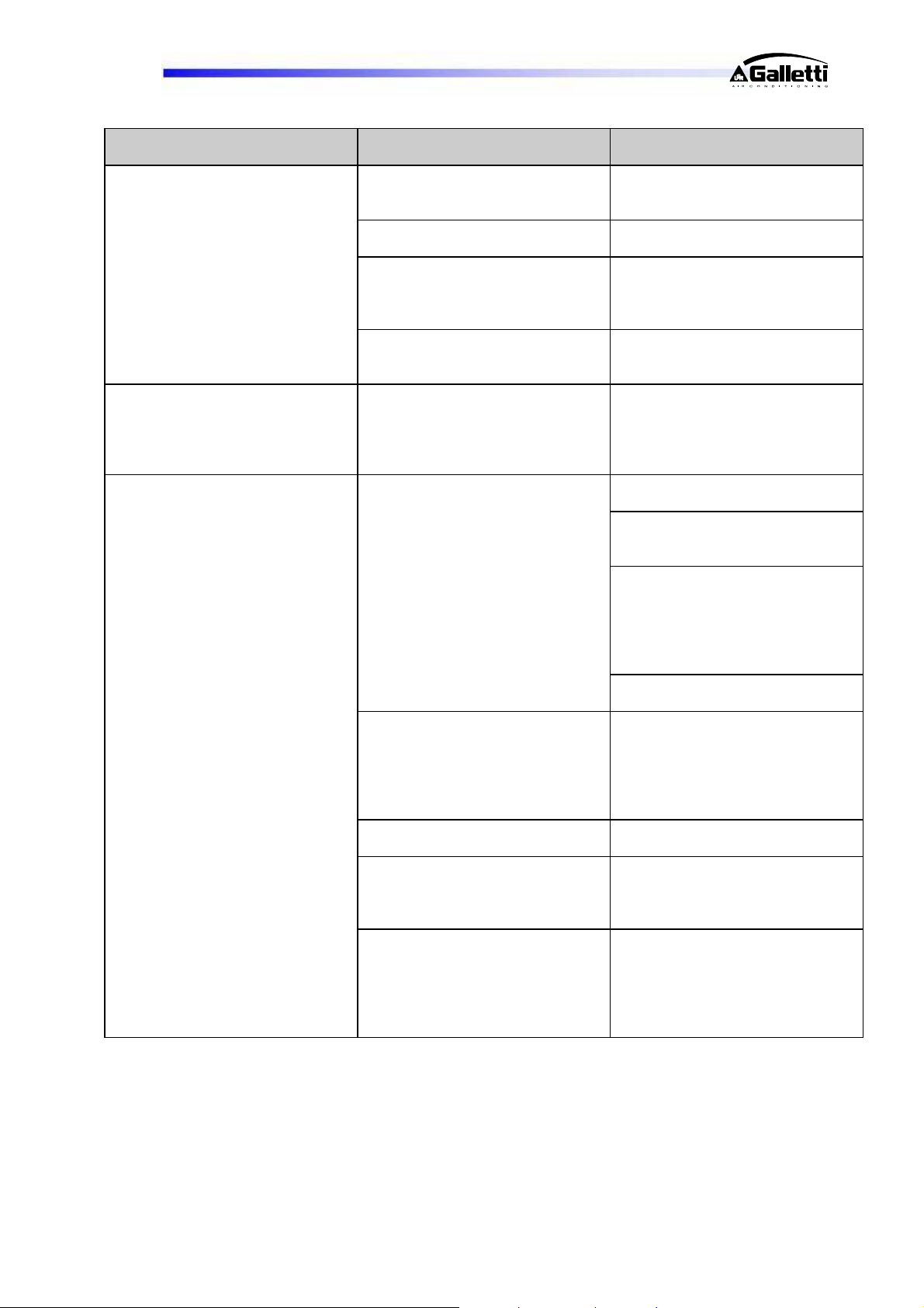
On the next pages you will find a list of the most common causes that may cause the chilling unit to fail or
malfunction. These causes are broken down according to easily identifiable symptoms.
You should be extremely careful when attempting to implement any of the possible
remedies suggested: overconfidence can result in injuries, even serious ones, to
inexpert individuals. Therefore, once the cause has been identified, you are advised to
contact the manufacturer or a qualified technician for help.
Plate heat
exchanger
Dryer filter
Cold water
inlet
Hydronic unit
one pump per
circuit
Cold water
outlet
Lamination
valves
Hot water
outlet
Hot water
inlet
RG66006889-Rev.01 31
Page 32
LCP
FAULT
The unit does not start.
The compressor is noisy.
Presence of abnormally high
pressure.
Possible causes Corrective actions
No power supply. Check that power is being supplied
both to the primary and auxiliary
circuits.
The electronic card is cut off from
the power supply.
Alarms have been triggered. Check whether any alarms are
The phase sequence is wrong. Reverse two phases in the primary
The compressor is rotating in the
wrong direction.
Insufficient flow of air to the
condenser.
Presence of air in the refrigerant
circuit, as revealed by the
presence of bubbles in the flow
indicator also with subcooling
values exceeding 5 °C.
Unit overcharged, as revealed by a
subcooling of more than 8 °C.
Thermostatic valve and/or filter
obstructed. These symptoms may
also occur in the presence of an
abnormally low pressure.
Insufficient flow of water in the
case of heat pump operation.
Check the protections.
signalled on the microprocessor
control panel, eliminate the causes
and restart the unit.
power line after disconnecting
them upstream from the unit.
Check the phase sequence relay.
Reverse the phases on the
terminal board after disconnecting
the unit and contact the
manufacturer.
Check whether all the fans are
turning properly.
Check the air T at the condenser
inlet and make sure no back
suction occurs.
Check whether the effective RMS
voltage to the fans is the
maximum. If necessary, check the
pressure transducers via the
revolution speed controller, where
present [optional].
Check the cleanliness of the finned
coils.
Drain and pressurise the circuit
and check for leaks. Generate a
slow vacuum [longer than 3 hours]
until reaching a pressure of 15 Pa
and then recharge in the liquid
phase.
Drain the circuit.
Check the temperatures upstream
and downstream from the valve
and filter and replace them if
necessary.
Check the water circuit for
pressure drops and/or whether the
pump is working properly [direction
of rotation]. Check the outgoing
water T and make sure it is less
than or equal to 45°C.
RG66006889-Rev.01 32
Page 33
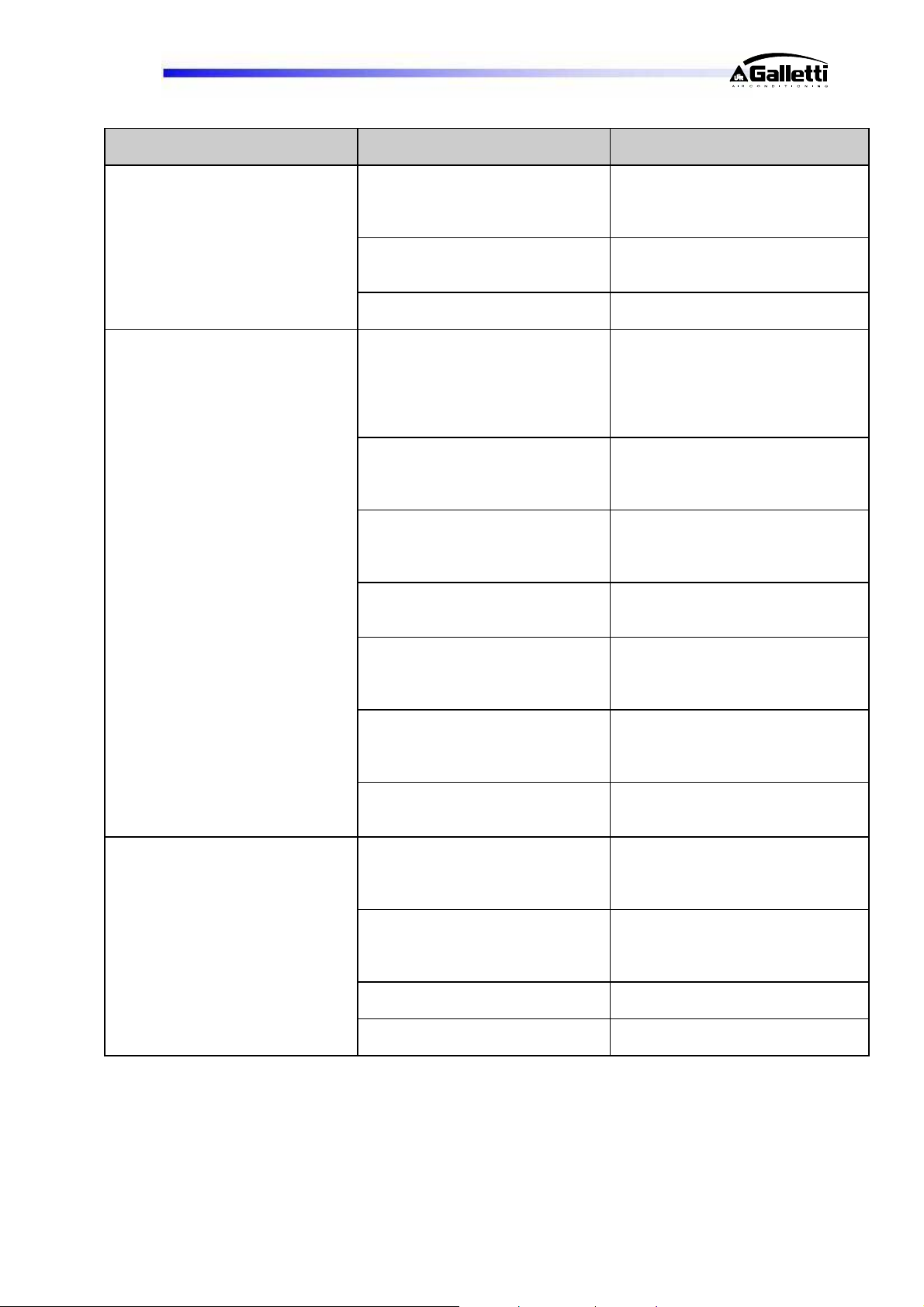
LCP
FAULT
Low condensation pressure.
Low evaporation pressure.
The compressor does not start.
Possible causes Corrective actions
Transducer fault. Check the transducers and the
efficiency of the needle pusher on
the Schrader valves they are
connected to.
Outdoor T too low and/or presence
of strong winds.
Low water T, in the case of heat
pump operation.
Insufficient flow of water. Check whether the pumps are
Malfunctioning of thermostatic
valve.
Filter clogged. Pressure drops upstream and
Low condensation T. Check the efficiency of the
Low level of refrigerant. Check the refrigerant level by
Coil covered with frost, in the case
of heat pump operation.
Low outdoor T, if the unit is
operating with the heat pump on.
The internal thermal protection
device has tripped.
The circuit breakers or line fuses
have been tripped by a short
circuit.
One of the high or low pressure
switches has tripped.
The phases have been reversed in
the distribution compartment.
Install the condensation control
device and/or protect the unit from
prevalent winds.
Check whether the thermal load is
compatible with the unit’s potential.
rotating in the right direction. Check
the water system for pressure
drops. Check the efficiency of the
pump system check valve
(optional).
Warming the bulb with your hand,
check whether the valve opens and
adjust it if necessary. If it does not
respond, replace it.
downstream from the filter should
not exceed 2°C. If they do, replace
the filter.
condensation control device [where
present].
measuring the degree of
subcooling; if it is below 2°C
replenish the charge.
Check whether the defrost
parameters have been properly set.
Check the efficiency of the 4-way
valve.
Check compliance with the
operating limits and eliminate any
bypasses and back flow of air.
In the case of compressors
equipped with a protection module,
check the thermal contact. Identify
the causes after restarting.
Pinpoint the cause by measuring
the resistance of the individual
windings and the insulation to the
casing before restoring power.
Check on the microprocessor,
eliminate the causes.
Check the phase sequence relay.
RG66006889-Rev.01 33
Page 34
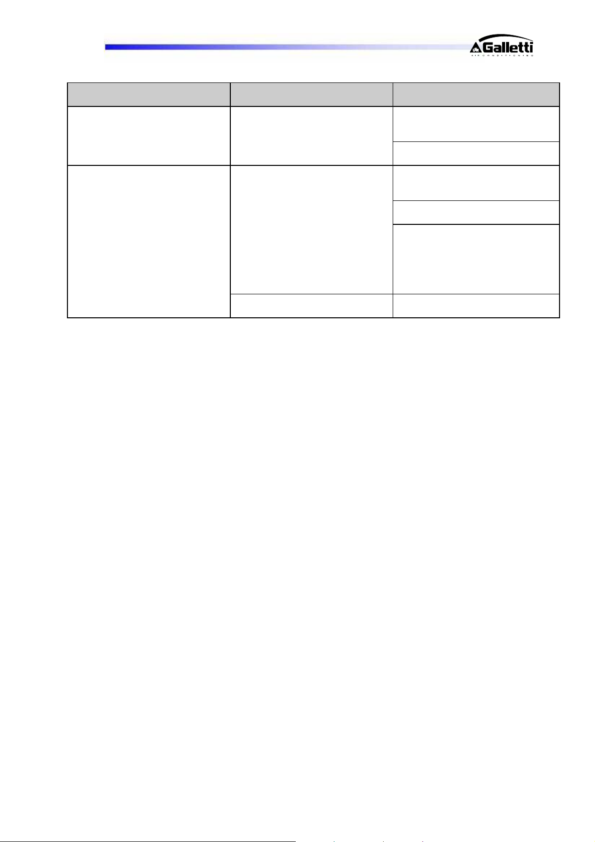
LCP
FAULT
High evaporation pressure.
Defrosting absent or incomplete
Possible causes Corrective actions
Water T too high. Check the thermal load and/or
efficiency of the thermostat
function.
Check the efficiency of the
thermostatic valve.
Error in parameter settings. Check the setting of the start and
end defrost parameters on the
microprocessor.
Check whether defrosting water is
properly drained from the coils.
Check the uniformity of the
refrigerant circuit outlet
temperatures at the top and bottom
of the coils: the maximum
temperature differential allowed is
10 °C. Check the refrigerant level.
The 4-way valve has failed to
work.
Check whether it is regularly
energized and deenergized.
13 WATER PRESSURE DROPS
13.1 PRESSURE DROPS IN EVAPORATOR
NB: for further details contact the HiRef technical department.
13.2 PRESSURE DROPS IN HEAT RECUPERATOR
NB: for further details contact the HiRef technical department.
RG66006889-Rev.01 34
Page 35
LCP
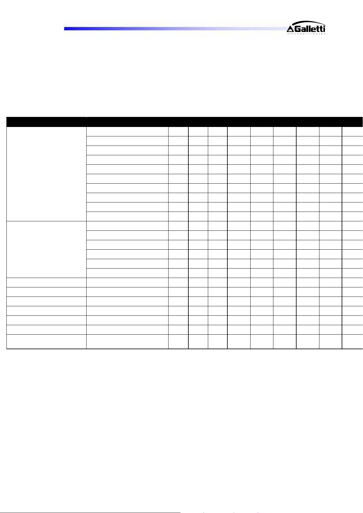
14 SUMMARY TECHNICAL DATA
14.1 STANDARD VERSION
LCP - HS / PS 041 051 061 071 081 094 104 124
Cooling capacity (1) kW 51,70 56,4 67.6 74,18 82.82 102.30 111.46 134.64
Total Input power (1) kW 15,93 17.90 20,4 22.9 26.64 32,30 36,50 43,42
EER (1) 3,25 3,14 3,31 3,23 3,11 3,17 3,05 3,10
Cooling capacity (2) kW 50,60 56,10 59,3 73,18 83.97 101.90 112.13 131.01
Heating capacity (2) kW 65,22 72,20 79,1 93.76 107.15 130.64 144.33 167.86
Total Input power (2) kW 16,29 18.12 22,0 23.41 26.45 32.59 36.23 45.08
Summer Mode
Winter Mode
Expansion tanks dm3 8 8 8 8 8 12 12 25
Tank capacity (*) dm3 200 200 220 220 220 340 340 600
Frame 1 1 2 2 2 3+ 3+ 4
Height
Length
Depth
Sound pressure @ 10 m
Q=2
(1) Summer mode for production of chilled water alone on exchanger “S1” @ 12/7°C with outdoor air 35°C.
(2) Summer mode for simultaneous production of chilled water on exchanger “S1” @ 12/7°C and hot water on
(3) Summer mode for production of hot water alone on exchanger “S2” @ 45/50 with outdoor air 35°C.
(4) Winter mode for production of hot water alone on exchanger “S1” @ 40/45°C with outdoor air 7°C RH90%
(5) Winter mode for production of hot water alone on exchanger “S2” @ 40/50 with outdoor air 7°C RH90%.
Total COP (2) (**) 7.68 7.57 7.79 7.71 7.83 7.69 7.57 6,2
Heating capacity (3) kW
Total Input power (3) kW
COP (3)
Heating capacity (4) kW 56.25 62.05 72.89 80.77 89.38 11.45 123.08 146.96
Total Input power (4) kW 15.96 17.83 20.78 23.18 26.07 31.90 35.49 44.53
COP (4) 3.52 3.48 3,51 3,48 3,46 3,49 3,47 3,30
Heating capacity (5) kW 55.63 61.26 71.98 79.64 89.14 110.25 121.39 145.08
Total Input power (5) kW 16 19.20 22.33 25.17 28.25 34.39 38.38 47.63
COP (5)
dB(A) 52 52 53 53 53 54 54 56
exchanger “S2” @ 40/45°C.
[possible with unit in version “H”].
77,81 86 100,44 111,01 124,3 154,24 170,45 199,68
18,18 20,21 23,43 26,09 28,96 36,33 40,4 49,82
4,28 4,26 4,29 4,25 4,29 4,25 4,22 4,01
3,23 3,19 3,22 3,16 3,16 3,21 3,16 3,05
mm 1720 1720 1720 1720 1720 1720 1720 1830
mm 2010 2010 2360 2360 2360 3540 3540 3540
mm 1185 1185 1185 1185 1185 1185 1185 1654
RG66006889-Rev.01 35
Page 36
LCP
5
4
6
4
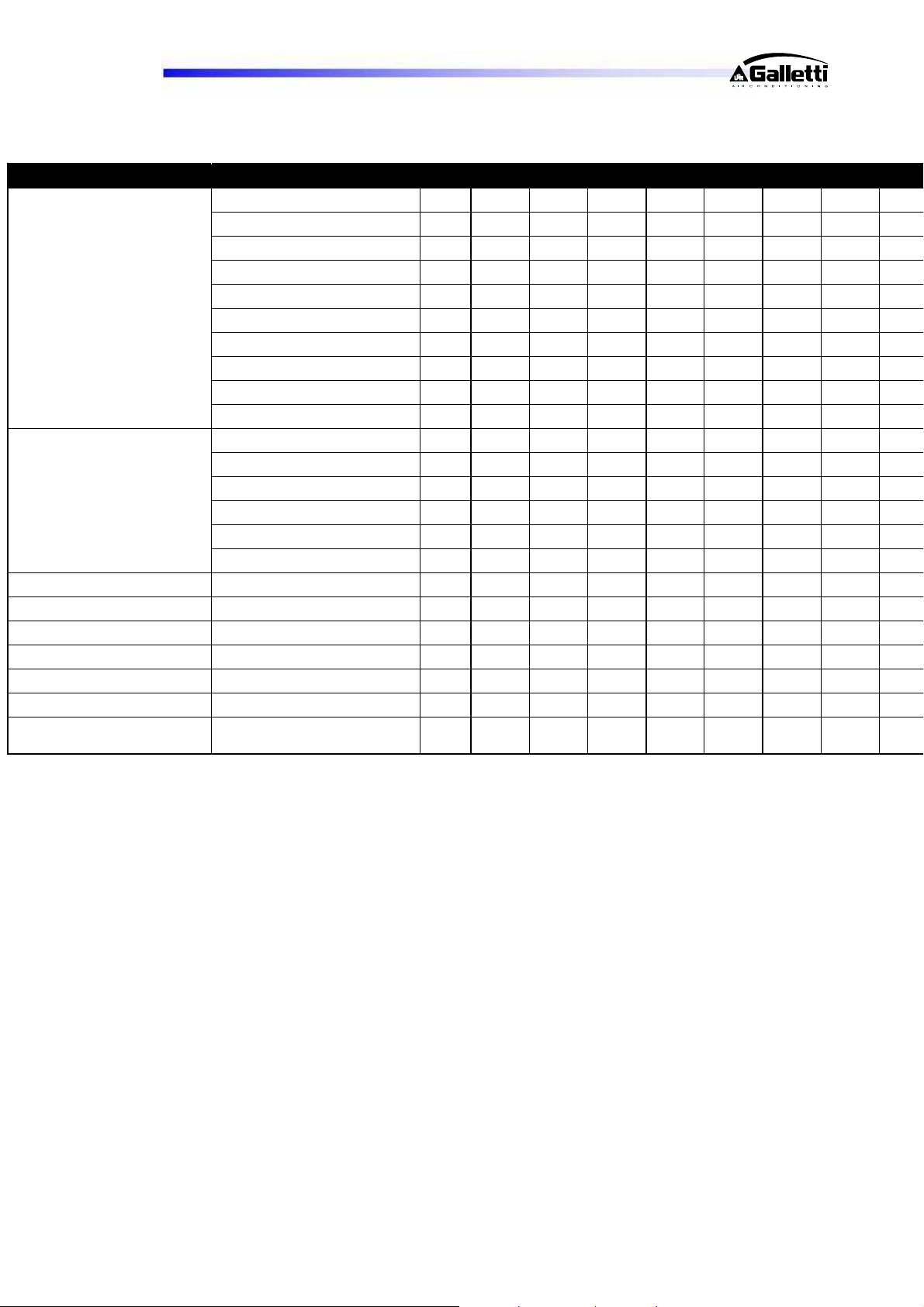
LCP - HS / PS 144 164 194 214 244 274 294 324
Cooling capacity (1) kW 14792 166.53 193,63 220,56 238,60 264,30 298.97 314.0
Total Input power (1) kW 48.42 54,84 66,19 74,60 83,14 98,3 101.96 114,
EER (1) 3,05 3,04 2,93 2.96 2.87 2,89 2,93 2.73
Cooling capacity (2) kW 144.86 165.08 197.74 222.23 245.72 268.79 304.5 326.6
Heating capacity (2) kW 186.26 211.79 252.69 286.12 315.58 345.39 390.66 422.7
Total Input power (2) kW 49.88 55.46 64.14 73.55 79.83 89.04 99.10 109.5
Summer Mode
Winter Mode
Expansion tanks dm3 25 25 25 25 25 25 25 25
Tank capacity (*) dm3 600 600 600 600 600 765 765 765
Frame 4 4 5 5 5 6 6 6
Height
Length
Depth
Sound pressure @ 10 m
Q=2
(1) Summer mode for production of chilled water alone on exchanger “S1” @ 12/7°C with outdoor air 35°C.
(2) Summer mode for simultaneous production of chilled water on exchanger “S1” @ 12/7°C and hot water on
(3) Summer mode for production of hot water alone on exchanger “S2” @ 45/50 with outdoor air 35°C.
(4) Winter mode for production of hot water alone on exchanger “S1” @ 40/45°C with outdoor air 7°C RH90%
(5) Winter mode for production of hot water alone on exchanger “S2” @ 40/50 with outdoor air 7°C RH90%.
Total COP (2) (**) 7.60 7.67 7.79 7.56 7.63 7.62 7.66 7.41
Heating capacity (3) kW
Total Input power (3) kW
COP (3)
218,11 250,03 291,94 339,2 368,62 408,75 459,56 468,1
54,96 61,17 70,72 81,35 89,05 99,49 110,46 121,4
3,97 4,09 4,13 4,17 4,14 4,11 4,16 3,85
Heating capacity (4) kW 162.66 180.94 211.29 246.24 266.66 294.59 330.97 340.8
Total Input power (4) kW 49.53 55.32 63.77 73.25 78.61 87.35 97.41 108.4
COP (4) 3.28 3,29 3,33 3,38 3,41 3,39 3,41 3,16
Heating capacity (5) kW 160.50 178.91 209.77 243.71 264.27 291.45 327.79 337.6
Total Input power (5) kW 53.34 59.52 69.09 78.92 84.41 93.82 104.35 115.5
COP (5)
mm 1830 1830 2174 2174 2174 2174 2174 217
mm 3540 3540 3540 3540 3540 4296 4296 429
mm 1654 1654 1654 1654 1654 1654 1654 165
3,01 3,01 3,04 3,09 3,13 3,11 3,14 2,92
dB(A) 56 57 57 58 58 58 59 59
exchanger “S2” @ 40/45°C.
[possible with unit in version “H”].
RG66006889-Rev.01 36
Page 37
LCP
14.2 LOW NOISE VERSION
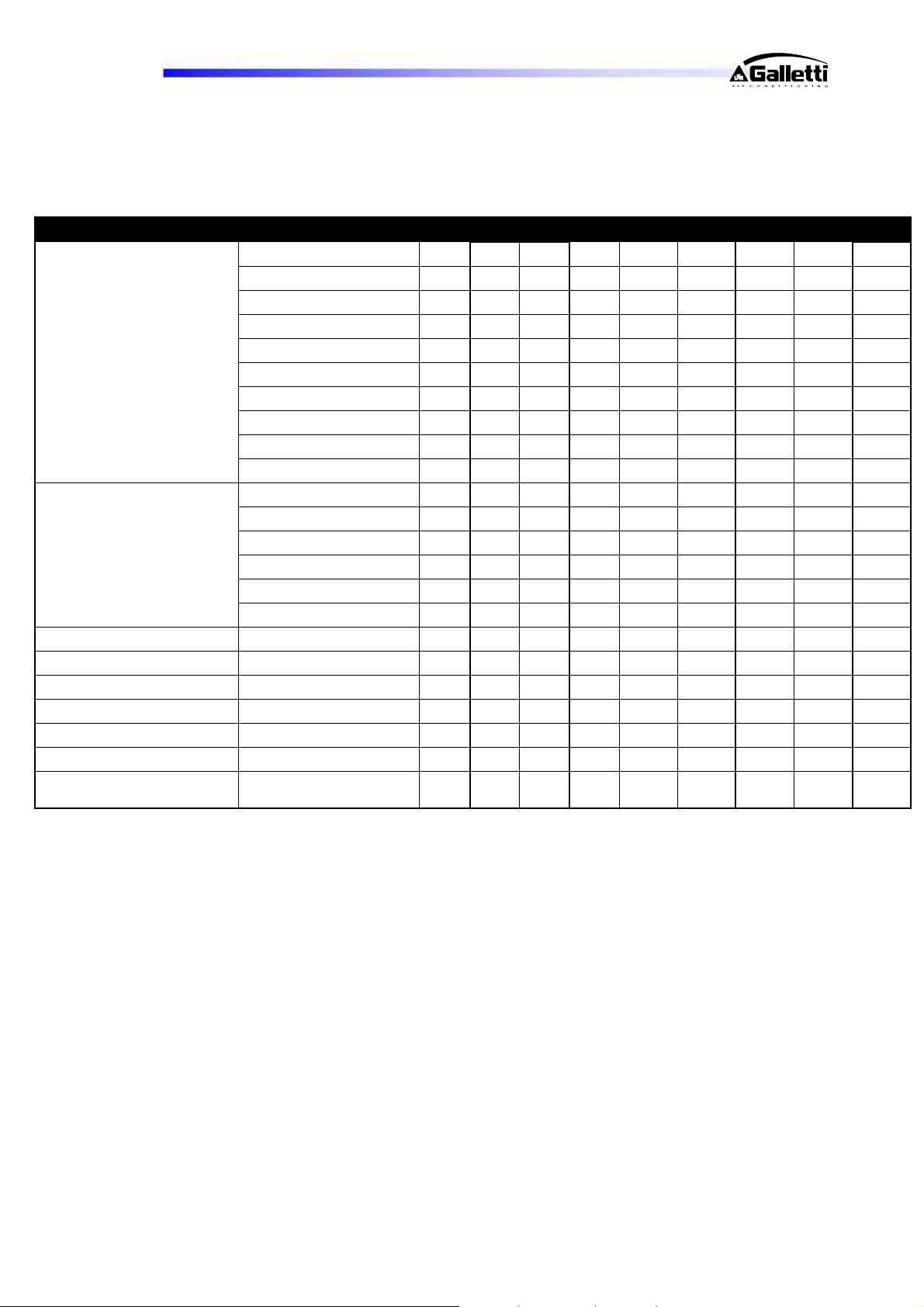
LCP - HL / PL 041 051 061 071 081 094 104 124
Cooling capacity (1) kW 49.60 53.84 65.05 70.82 78.62 98.03 105.94 127.62
Total Input power (1) kW 16.22 18,54 20,64 23,56 27,73 33.05 37.82 44.39
EER (1) 3,1 2,9 3,1 3,0 2,8 2,9 2,7 2,8
Cooling capacity (2) kW 50.86 56.10 66.10 73.18 83.97 101.90 112.13 131.01
Heating capacity (2) kW 65.22 72.20 84.47 93.76 107.15 130.64 144.33 167.86
Total Input power (2) kW 15.66 17.49 20.13 22.47 25.21 31.33 34.98 42.80
Summer Mode
Winter Mode
Expansion tanks dm3 8 8 8 8 8 12 12 25
Tank capacity (*) dm3 200 200 220 220 220 340 340 600
Frame 1 1 2 2 2 3+ 3+ 4
Height
Length
Depth
Sound pressure @ 10 m
Q=2
Total COP (2) (**) 7.68 7.57 7.79 7.71 7.83 7.69 7.57 7.71
Heating capacity (3) kW
Total Input power (3) kW
COP (3)
Heating capacity (4) kW 55.72 61.47 72.22 80.03 88.54 110.40 121.91 141
Total Input power (4) kW 15.32 17.19 19.83 22.23 25.14 30.63 34.22 42.16
COP (4)
Heating capacity (5) kW
Total Input power (5) kW
COP (5)
dB(A) 45 46 48 48 48 49 49 51
77,12 85,23 99,12 109,24 123,37 152,21 167,41 193,59
17,54 19,57 22,48 25,04 27,91 35,02 39,11 47,48
4,40 4,36 4,41 4,36 4,42 4,35 4,28 4,08
3,64 3,58 3,64 3,60 3,52 3,60 3,56 3,34
55,13 60,7 70,7 78,32 87,53 108,39 119,32 138,73
16,57 18,56 21,37 24,13 27,34 32,97 36,94 45,27
3,33 3,27 3,31 3,25 3,20 3,29 3,23 3,06
mm 1720 1720 1720 1720 1720 1720 1720 1830
mm 2010 2010 2360 2360 2360 3540 3540 3540
mm 1185 1185 1185 1185 1185 1185 1185 1654
(1) Summer mode for production of chilled water alone on exchanger “S1” @ 12/7°C with outdoor air 35°C.
(2) Summer mode for simultaneous production of chilled water on exchanger “S1” @ 12/7°C and hot water on
exchanger “S2” @ 40/45°C.
(3) Summer mode for production of hot water alone on exchanger “S2” @ 45/50 with outdoor air 35°C.
(4) Winter mode for production of hot water alone on exchanger “S1” @ 40/45°C with outdoor air 7°C RH90%
[possible with unit in version “H”].
(5) Winter mode for production of hot water alone on exchanger “S2” @ 40/50 with outdoor air 7°C RH90%.
RG66006889-Rev.01 37
Page 38
LCP
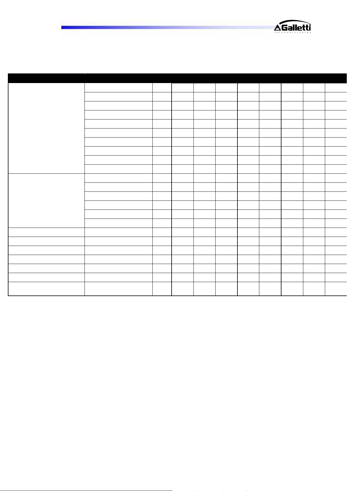
LCP - HL / PL 144 164 194 214 244 274 294 324
Cooling capacity (1) kW 138.51 153.76 187.63 215.12 232.67 258.62 291.70 304.57
Total Input power (1) kW 50.51 58.58 66.59 75.13 84.02 91.70 103.37 117.32
EER (1) 2,7 2,6 2,7 2,9 2,8 2,7 2,7 2,6
Cooling capacity (2) kW 144.86 165.08 197.74 222.23 245.72 268.79 304.50 326.61
Heating capacity (2) kW 186.26 211.79 252.69 286.12 215.58 245.39 390.66 422.71
Total Input power (2) kW 47.60 53.18 61.86 71.27 77.55 86.74 96.80 107.26
Summer Mode
Winter Mode
Expansion tanks dm3 25 25 25 25 25 25 25 25
Tank capacity (*) dm3 600 600 600 600 600 765 765 765
Frame 4 4 5 5 5 6 6 6
Height
Length
Depth
Sound pressure @ 10 m
Q=2
Total COP (2) (**) 7.60 7.67 7.79 7.56 7.63 7.62 7.66 7.41
Heating capacity (3) kW
Total Input power (3) kW
COP (3)
Heating capacity (4) kW 155.52 178.39 210.31 245.36 266.66 294.59 330.97 340.81
Total Input power (4) kW 47.06 53.08 61.50 70.68 76.33 85.05 95.11 106.10
COP (4)
Heating capacity (5) kW
Total Input power (5) kW
COP (5)
dB(A) 51 52 53 54 54 55 55 55
214,26 245,93 290,62 339,2 368,62 405,16 459,56 468,18
52,67 58,67 68,44 79,07 86,77 97,12 108,16 119,17
4,07 4,19 4,25 4,29 4,25 4,17 4,25 3,93
3,30 3,36 3,42 3,47 3,49 3,46 3,48 3,21
153,7 178,87 207,15 242,62 263,1 290,44 326,32 336,09
50,88 57,32 66,57 76,65 82,11 91,16 102,03 114,27
3,02 3,12 3,11 3,17 3,20 3,19 3,20 2,94
mm 1830 1830 2174 2174 2174 2174 2174 2174
mm 3540 3540 3540 3540 3540 4296 4296 4296
mm 1654 1654 1654 1654 1654 1654 1654 1654
(1) Summer mode for production of chilled water alone on exchanger “S1” @ 12/7°C with outdoor air 35°C.
(2) Summer mode for simultaneous production of chilled water on exchanger “S1” @ 12/7°C and hot water on
exchanger “S2” @ 40/45°C.
(3) Summer mode for production of hot water alone on exchanger “S2” @ 45/50 with outdoor air 35°C.
(4) Winter mode for production of hot water alone on exchanger “S1” @ 40/45°C with outdoor air 7°C RH90%
[possible with unit in version “H”].
(5) Winter mode for production of hot water alone on exchanger “S2” @ 40/50 with outdoor air 7°C RH90%.
RG66006889-Rev.01 38
Page 39
LCP
15 SUMMARY TABLE OF WEIGHTS
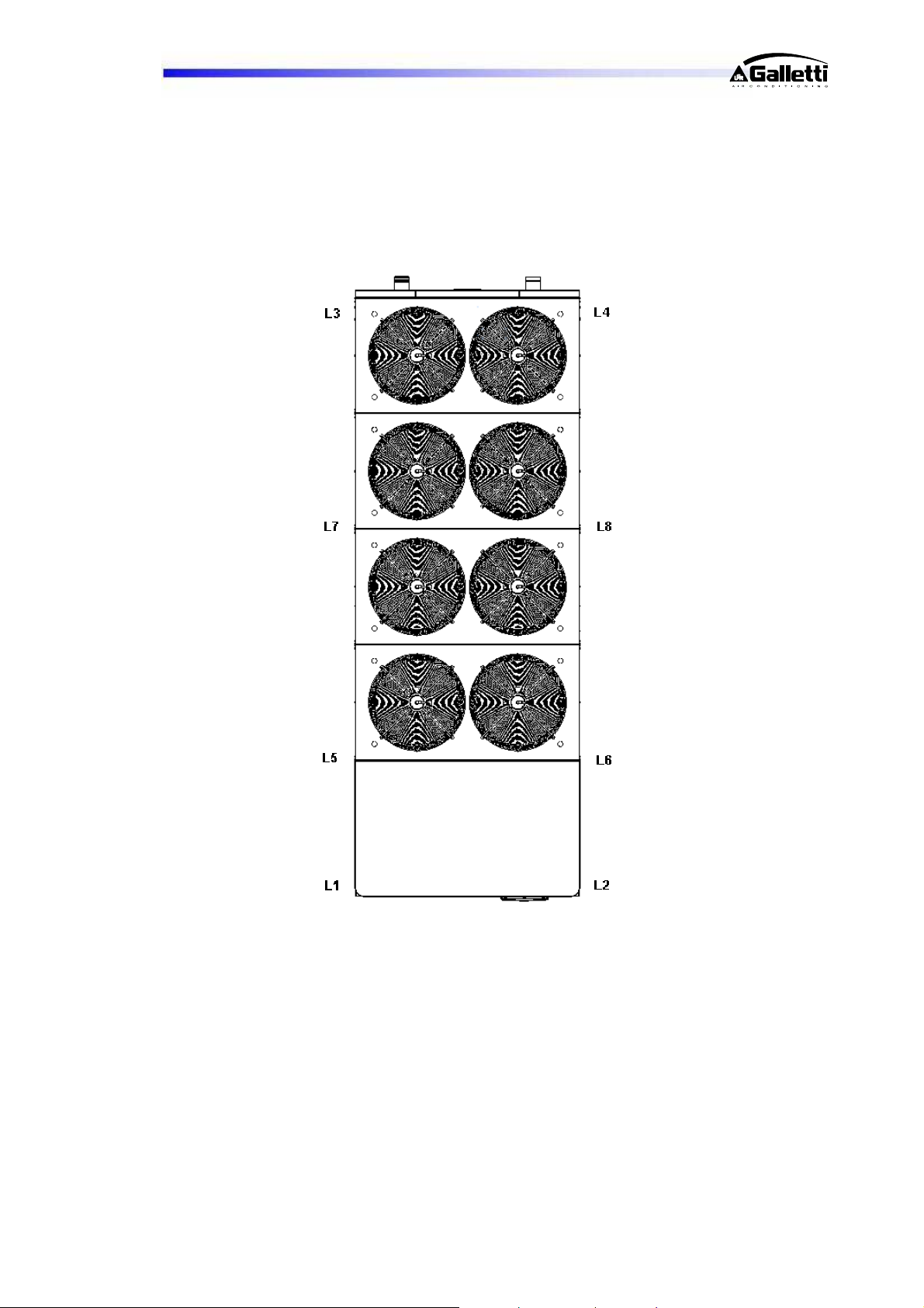
This drawing shows the points of the unit for which the weights for the basic version were calculated,
multi-purpose in configuration without pumps, without tank and empty with treated water. They are
shown on the following table.
RG66006889-Rev.01 39
Page 40

LCP
Multi-purpose LCP weights
HS-HL-
PS-PL
SIZE 41 51 61 71 81 94 104 124 144 164 194
FRAME 1 1 2 2 2 3+ 3+ 4 4 4 4
total [kg] 620 620 725 730 750 1095 1095 1435 1465 1615 1635
L1 242 242 282 284 291 172 172 227 232 254 257
L2 242 242 282 284 291 172 172 227 232 254 257
L3 68 68 81 82 84 102 102 132 135 150 152
L4 68 68 81 82 84 102 102 132 135 150 152
L5 172 172 227 232 254 257
L6 172 172 227 232 254 257
L7 102 102 132 135 150 152
L8 102 102 132 135 150 152
HS-HL-
PS-PL
SIZE 214 244 274 294 324
FRAME 5 5 6 6 6
HS-HL-
PS-PL
HS-HL-
PS-PL
HS-HL-
PS-PL
HS-HL-
PS-PL
HS-HL-
PS-PL
HS-HL-
PS-PL
HS-HL-
PS-PL
HS-HL-
PS-PL
HS-HL-
PS-PL
HS-HL-
PS-PL
HS-HL-
PS-PL
HS-HL-
PS-PL
HS-HL-
PS-PL
HS-HL-
PS-PL
total [kg] 1710 1810 2102 2137 2188
L1 269 284 404 415 420
L2 269 284 404 415 420
L3 159 169 244 248 255
L4 159 169 244 248 255
L5 269 284 404 415 420
L6 269 284 404 415 420
L7 159 169
L8 159 169
RG66006889-Rev.01 40
Page 41
LCP
15.1 PUMPING AND STORAGE SYSTEMS
LCP units may be equipped with 6 types of pumping systems, complete with expansion tank:
- single standard pump
- single uprated pump
- standard pump and back-up pump
- uprated pump and back-up pump
- standard pump for combined operation
- uprated pump for combined operation.
In the case of pump systems including a back-up pump, the microprocessor controls the pumps in such a
way as to equally divide the hours of operation, changing over the pumps in the event of a fault.
All of these considerations can also be chosen on the DHW side.
RG66006889-Rev.01 41
Page 42
LCP
RG66006889-Rev.01 42
Page 43
LCP
RG66006889-Rev.01 43
Page 44

40010 Bentivoglio (BO)
Via Romagnoli 12/a
Tel. 051/8908111
Fax. 051/8908122
www.galletti.itCompany UNI EN ISO 9001 and OHSAS 18001 certified
 Loading...