

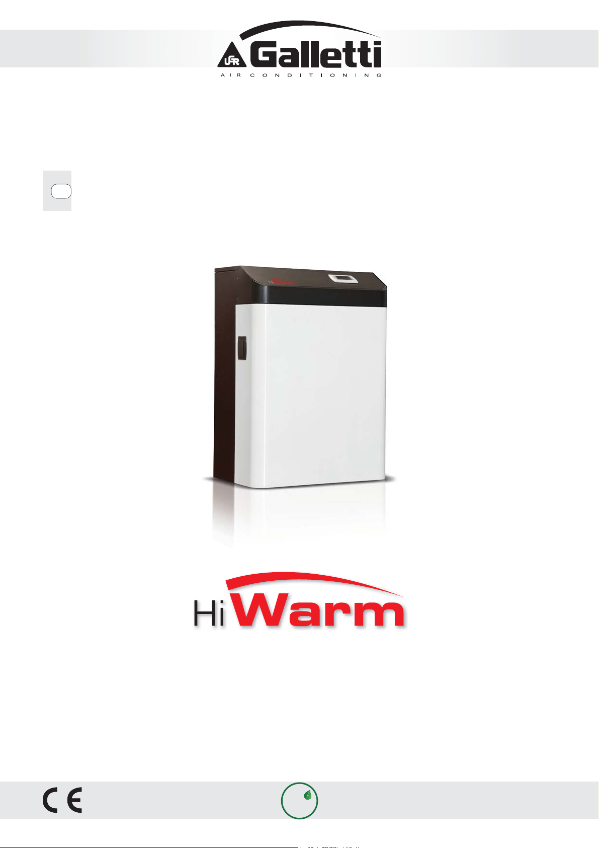
Galletti HiWarm Series, HiWarm 012, HiWarm 033, HiWarm 022 Installation, Use And Maintenance Manual
Page 1
GB
INSTALLATION, USE AND MAINTENANCE MANUAL
12 kW - 22 kW - 33 kW
MULTIFUNCTION UNIT: AIR-WATER HEAT PUMP
eco
R410A
Page 2

Page 3
HiWarm
MULTIFUNCTION UNIT: AIR-WATER HEAT PUMP
WARNING
WARNING
Dear Customer,
Whilst thanking you for having chosen a product of ours, we are pleased to provide this manual for
optimal use of our product for maximum comfort.
Please carefully read the recommendations provided in the following pages and place the manual at
the disposal of the unit managers and maintenance technicians.
Our company is at your disposal for any questions you may have both during the unit start-up phase or
any other time.
Our Technical Department is at your disposal for any assistance and spare parts you may require,
especially during routine or special maintenance.
READ THIS MANUAL CAREFULLY BEFORE USING THE UNIT.
Declaration of conformity
The declaration of conformity is attached separately to the documents on board the unit, usually
placed inside the circuit compartment.
Please nd our contact details below for a more rapid service:
Galletti S.p.A.
Via L.Romagnoli 12/a
40010 Bentivoglio (BO) ITALY
Tel + 39 051 8908111
Fax + 39 051 8908122/3
e-mail : [email protected]
All copying, even partial, of this manual is strictly forbiddenRG66007967 - Rev 02
3
Page 4

HIWARM
4
All copying, even partial, of this manual is strictly forbidden RG66007967 - Rev 02
Page 5

START-UP INSTRUCTIONS
1 YOUR INSTALLATION
All the tips required for a perfect installation of the equipment are found in the installation manual.
It is impor
with a mesh that does not exceed 1 mm.
2 YOUR CONNECTION
All connections must be made correctly. The COMMISSIONING REQUEST FORM lists all that must be
checked befor
3 YOUR REQUEST
Send the request form found in the unit documentation by fax, at least one week in advance. Should
this form not be f
Tel. (+39) 051 8908111 - Fax (+39) 051 8908122 - e-mail: assistenza@galletti.it
4 OUR APPOINTMENT
Galletti will organise this by asking the Authorised Technical Service Centre in your area to contact
you.
tant to place a net lter at both water circuit inlets, which must be made of stainless steel
e requesting unit start-up.
ound, please contact GALLETTI:
5 OUR
TEST
All the preliminary checks and unit test will be performed together with your personnel.
our personnel will be provided with instructions for correct unit management.
Y
6 OUR GUARANTEE
The Authorised Technical Service Centre will issue a test certicate once the test is performed, which
repr
esents the warranty of the unit.
Galletti S.p.A. provides you with a customised maintenance program.
All copying, even partial, of this manual is strictly forbiddenRG66007967 - Rev 02
5
Page 6

HIWARM
CONTENTS
1 - GENERAL DESCRIPTION 8
1.1 PRECAUTIONS FOR USE 8
1.2 PREMISE 8
1.3 LIABILITY 9
1.4 INTENDED USE 9
1.5 UNIT IDENTIFICATION 10
1.6 GENERAL INSTRUCTIONS 11
2 - SAFETY REQUIREMENTS 12
2.1 GENERAL SAFETY STANDARDS 12
2.1.1 Be familiar with the unit 12
2.1.2 Wear protective clothing 12
2.1.3 Use safety equipment 12
2.1.4 Maintenance and inspection warning signs 12
2.2 GENERAL PRECAUTIONS 13
2.2.1 Safety precautions 14
2.2.2 Accident prevention safety 14
2.2.3 Operational safety 14
2.2.4 Residual risk areas 14
2.3 LOCATION OF THE SAFETY LABELS 15
2.3.1 Description of the safety labels 15
2.4 GENERAL SAFETY RULES 17
2.4.1 Attention and maintenance 17
2.4.2 Fire extinguisher and rst aid 17
2.5 MAINTENANCE PRECAUTIONS 18
2.5.1 Tools 18
2.5.2 Personnel 18
2.5.3 Keeping the unit clean 18
2.5.4 Warning signs 18
3 - DESCRIPTION OF THE PRODUCT 19
3.1 THE RANGES 19
3.2 MAIN COMPONENTS OF THE INDOOR UNIT 21
3.3 SYNCHRONOUS MOTORS 26
3.4 MAIN COMPONENTS OF THE OUTDOOR UNIT 27
3.5 RANGE AND OPERATION 28
3.6 PIPING AND LOAD DESIGN CRITERIA 30
3.7 OPERATING LIMITS 31
4 - INSPECTION, TRANSPORT AND POSITIONING 34
4.1 INSPECTION 34
4.2 LIFTING AND TRANSPORT 34
4.3 UNPACKING 34
4.4 POSITIONING AND INSTALLATION 34
6
All copying, even partial, of this manual is strictly forbidden RG66007967 - Rev 02
Page 7

CONTENTS
5 - CONNECTIONS 35
5.1 WATER CONNECTIONS 35
5.1.1 General guidelines for the water connections 35
5.1.2 Technical data of the hydraulic pumps 36
5.2 ELECTRICAL CONNECTIONS 38
6 - MANAGEMENT AND CONTROL 40
6.1 GWEB OPERATION 40
6.2 ELECTRICAL LOAD MANAGEMENT FUNCTION 41
6.3 USER INTERFACE 42
6.3.1 Description of the keypad 42
6.3.2 Main screen 43
6.3.3 Selecting the control mode 43
6.3.4 Selecting the set-point 46
6.3.5 Alarms 47
6.3.6 Operating mode 49
7 - MAINTENANCE AND AFTER SALES SERVICE 50
7.1 TROUBLESHOOTING 50
8 - OPTIONAL STORAGE TANKS 52
9 - TECHNICAL DATA 53
10 - DECOMMISSIONING THE UNIT 55
10.1 ENVIRONMENTAL PROTECTION 55
11 - WATER PRESSURE DROPS 55
11.1 EVAPORATOR PRESSURE DROPS 55
11.2 HEAT RECOVERY UNIT PRESSURE DROPS 55
12 - R410A REFRIGERANT SAFETY DATA SHEET 56
All copying, even partial, of this manual is strictly forbiddenRG66007967 - Rev 02
7
Page 8
HIWARM
1 - GENERAL DESCRIPTION
1.1 PRECAUTIONS FOR USE
The operating rules in this manual are solely applicable for the following Models:
HiWarm
The instructions manual must be read and used as follows:
- every unit operator and maintenance technician must carefully read the entire manual and comply with that stipulated
therein;
- the employer is obliged to ensure that the operator satises the aptitude requisites for unit operation and has carefully
read the manual;
- read the instructions manual carefully and consider it an integral part of the unit;
- the instructions manual must be readily available to the operating personnel and maintenance technicians;
- keep the manual throughout the life of the unit;
- make sure that any update is included in the text;
- pass on the manual to any other use or subsequent owner of the unit;
- use the manual in such a way so as not to damage any part of the content;
- for not reason whatsoever are parts of the manual to be removed, torn or rewritten;
- keep the manual away from humidity and heat;
- if the manual is lost or partially damaged and therefore the contents can no longer be read entirely, it is advisable to
request a new manual from the manufacturer by communicating the code found on the cover or the serial number of the
unit.
Pay utmost attention to the following symbols and their meaning. Their purpose is to highlight specic information such as:
WARNING
DANGER
ATTENTION
With reference to additional information or tips for the unit to be used correctly.
With reference to dangerous situations that could arise while using the unit, in order
guarantee personal safety.
With reference to dangerous situations that could arise while using the unit, in order to
prevent damaging objects and the unit itself.
1.2 PREMISE
The operating rules described in this manual are an integral part of the unit supply.
These rules are also intended for the previously trained operator specically to operate this type of unit and contain all the
necessary and important information for operating safety and optimal, proper use of the unit.
Hurried and incomplete training leads to improvisation, which is the cause of many accidents.
The following recommendations must be read carefully before starting work and strictly complied with:
- the operator must always have the instructions manual at his disposal;
- plan each operation carefully;
- before starting work, make sure the safety devices function correctly and you have no doubts on how they work; otherwise,
do not start-up the unit;
- strictly comply with the precautions regarding specic risks referred to in this manual;
- preventive and thorough maintenance guarantees constant enhanced unit operating safety. Never delay repairs and
always have them carried out solely by qualied personnel; only original spare parts are to be used.
8
All copying, even partial, of this manual is strictly forbidden RG66007967 - Rev 02
Page 9
1.3 LIABILITY
The MANUFACTURER cannot be held liable for any personal accident or damage to property, which may derive from:
- failure to comply with the instructions provided in this manual regarding unit management, use and maintenance;
- violent actions or incorrect manoeuvres when performing maintenance on the unit;
- alterations made to the unit without prior written authorisation from the MANUFACTURER;
- incidents beyond the normal and proper use of the unit.
In any case, if the user attributes the incident to a defect in the unit, he must prove that the damage caused was a main and
direct consequence of this “defect”.
ATTENTION
- When installing or servicing the unit the rules stipulated in this manual must be complied
with together with those on board the unit and in any case take all the precautions
necessary.
- The pressurised uids in the cooling circuit and the presence of electrical components can cause hazardous
situations during installation and maintenance operations.
- Therefore, only qualied personnel may perform any work on the unit.
- THE UNIT MUST ONLY BE COMMISSIONED BY QUALIFIED PERSONNEL, AUTHORISED BY THE COMPANY PLACING IT
ON THE MARKET (SEE ATTACHMENT).
- FAILURE TO COMPLY WITH THE RULES STIPULATED IN THIS MANUAL AND ANY ALTERATION TO THE UNIT WITHOUT
PRIOR AUTHORISATION WILL IMMEDIATELY RENDER THE WARRANTY NULL AND VOID.
- Before performing any work on the unit, make sure it has been disconnected from the power supply.
- Only original spare parts must be used for repairs or maintenance operations. The MANUFACTURER declines all
liability for damage deriving from non-compliance with the above-mentioned points.
- The unit is covered by the warranty according to the contractual agreements for the sale.
- However, the warranty is rendered null and void if the regulations and user instructions stipulated in this manual
are not complied with.
- If a fault should occur, do not try to repair it yourself or have an unauthorised technician perform the repairs. The
warranty will otherwise be rendered null and void.
1.4 INTENDED USE
HiWarm is a residential air-water heat pump that exchanges heat with the external air and, with no combustion or ame,
warms or cools the home and autonomously produces technical hot water for domestic purposes.
Their use is recommended within the operating limits specied in this manual, otherwise the warranty cover provided for in
the sales contract will be rendered null and void.
Any other use is to be considered inappropriate and the manufacturer declines all liability for any damage caused to persons,
property or the unit that may derive from such use.
DANGER
- Set in unit in environments where there is no risk of explosion, corrosion or re.
- Improper use could cause serious repercussions on the unit.
- All routine and special maintenance operations must be performed with the unit o and
the power supply disconnected.
- Wait about 30 minutes after switching the unit o before performing any maintenance in order to prevent burns.
All copying, even partial, of this manual is strictly forbiddenRG66007967 - Rev 02
9
Page 10
HIWARM
ATTENTION
- Before performing any work on the unit, each operator must be perfectly aware of how the
unit and its controls work and must have read and understood all the technical information
in this manual.
- It is forbidden to use the unit in conditions or for purposes other than those stipulated in this manual and the
MANUFACTURER cannot be liable for faults, problems or accidents due to non-compliance with this prohibition.
- Do not repair the high pressure pipes with welding.
- It is prohibited to tamper with, alter or modify, even partially, the systems or equipment referred to in the
instructions manual, particularly the guards and symbols regarding personal safety.
- It is also prohibited to operate in any way other than that stipulated or disregard required safety operations.
- Safety guidelines together with general information provided in this manual are particularly important.
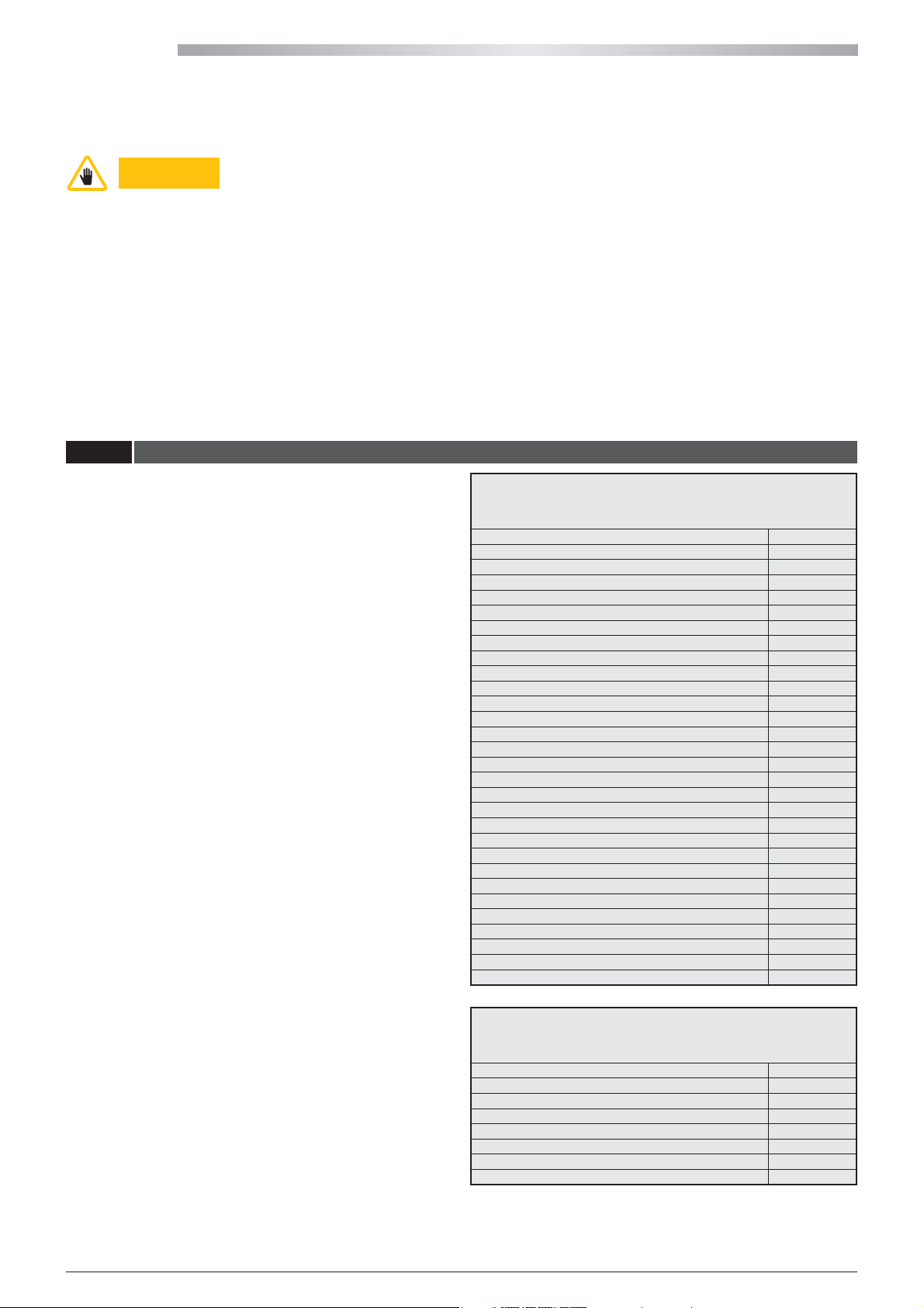
1.5 UNIT IDENTIFICATION
Each unit is distinguished by an identication label on the
frame, which bears all the data required for installation,
maintenance and unit traceability. Take note of the model,
serial number, the denitive refrigerant charge and the
reference drawings of the unit found at the end of this
manual, in order to be easily retrieved if the data label
deteriorates and maintenance is required.
CЄ 0398
Modello - Model HWM0XXP
Matricola - Serial number HFXXXXXXXXX
Data di produzione - Date of production 20-06-11
Categoria PED/ CE 97/23 Category II
Procedura di valutazione conformità - Conformity module D1
Massima pressione esercizio - Max working pressure [bar-r] 41,5
"Max pressione esercizio lato bassa pressione (carcassa compr.)
Max working pressure low pressure side (compr. shell) [bar-r]" 41,5
Max temp. di stoccaggio - Max storage temperature [°C] 42°C
Max temp. funzionamento - Max ambient working temperature [°C] 42° C
Min.temp.ambiente di funzionamento-Min ambient working temp. [°C ] -15°C
Potenza frigorifera nominale - Nominal Cooling Capacity [ kW ] /
Potenza nominale in riscaldamento - Nominal Heating Capacity [ kW ] /
Refrigerante - Refrigerant [Ashrae 15/1992] R410A
Carica refrigerante - Refrigerant charge [kg] (
Carica refrigerante denitva - Denitive Refrigerant charge [kg] (
Peso a vuoto - Empty weight [kg] 170
Taratura press. lato ALTA - HIGH pressure Switch Set [bar-r] 41,5
Taratura press. lato BASSA - LOW pressure Switch Set [bar-r] 1,5
"Taratura valvola sicurezza refrigerante
Safety valve refrigerant Set [bar-r]" "Taratura valvola sicurezza acqua
Safety valve water side Set [bar-r]" Alimentazione - Power supply 230/1/50Hz
Potenza assorbita Nominale - Nominal power input [kW] 5
Corrente nominale - Nominal absorbed current [A] 22
Corrente massima - Full load ampere FLA [A] 22
Corrente di spunto - Starting Current LRA [A] 0,0
Schema elettrico - Wiring diagram HF620AXXXX
Schema frigorifero - Refrigeration diagram HF630AXXXX
MANUFACTURER DATA
1
*)(precharge)
2
*)
1
*) The indicated refrigerant charge is preloaded inside the unit before leaving
(
the factory.
2
(
*) The denitive refrigerant charge must be written by the technician who
installs the unit and once installation is complete.
10
All copying, even partial, of this manual is strictly forbidden RG66007967 - Rev 02
MANUFACTURER DATA
CЄ 0398
Modello - Model HWO0XX
Matricola - Serial number HFXXXXXXXXX
Data di produzione - Date of production 20-06-11
Peso a vuoto - Empty weight [kg] 50
Alimentazione - Power supply 230/1/50Hz
Potenza assorbita Massima - Maximum power input [kW] 0,4
Corrente massima - Full load ampere FLA [A] 1,66
Corrente di spunto - Starting Current LRA [A] 0,0
Page 11

1.6 GENERAL INSTRUCTIONS
ATTENTION
- This manual indicates the intended use of the unit and provides instructions regarding transport, installation,
assembly, adjustment and use. It provides information regarding maintenance, ordering spare parts, the presence
of residual risks and personnel training.
- It is important to remember that the use and maintenance manual can never replace adequate user experience.
This manual represents a reminder of the main operations to be performed by operators who have received
specic training, for example by attending training courses held by the manufacturer, with reference to particular
maintenance operations.
- This manual is to be considered an integral part of the unit and must be stored near the unit in a special container
until the unit is demolished. Request a new copy from the manufacturer if it is lost or deteriorated.
- Make sure all the users have understood the user instructions well together with the meaning of any symbols on
the unit.
- Potential accidents can be prevented by following these technical instructions with reference to the Machinery
Directive 2006/42/EC and subsequent amendments.
- In any case, always comply with the national safety regulations.
- Do not remove or damage the safety devices, labels and notices, especially those imposed by law.
- Adhesive labels intended for safer use are applied to the unit, therefore, it is very important to replace them if they
become illegible.
- This manual reects the applicable technology at the time the unit is sold and cannot be considered inadequate
due to subsequent updates based on new experience.
- The MANUFACTURER has the right to update the production and manuals, without being obliged to update
previous production and manuals, except for exceptional cases.
- Please call on the telephone numbers found in this manual for any requests for updates of the use and maintenance
manual or supplements, which are to be considered an integral part of the manual.
- Contact the MANUFACTURER for further information and to submit any proposals on how to improve the manual.
- The MANUFACTURER kindly asks you to report the address of the new owner if the unit is passed on to third
parties, in order to facilitate forwarding any supplements of the manual to the new user.
- It must be stored carefully in a place that is known by the user of the unit, managers
and operators in charge of transport, installation, use, maintenance, repairs and nal
dismantling.
All copying, even partial, of this manual is strictly forbiddenRG66007967 - Rev 02
11
Page 12
HIWARM
2 - SAFETY REQUIREMENTS
2.1 GENERAL SAFETY STANDARDS
2.1.1 Be familiar with the unit
The unit must only be used by qualied personnel, who is obliged to be aware of the lay-out and function of all the controls,
instruments, indicators, warning lights and various labels.
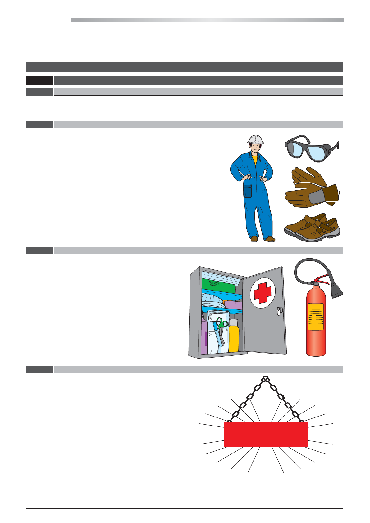
2.1.2 Wear protective clothing
Every operator must use personal protective equipment
such as gloves, helmet, safety goggles, safety shoes and
noise protection ear mus.
2.1.3 Use safety equipment
Place a rst aid kit and a re extinguisher near the unit.
The extinguisher must always be fully loaded. Use it
according to the Standards in force.
2.1.4 Maintenance and inspection warning signs
Apply a "WORKS IN PROGRESS" sign on all sides of the unit.
Carefully check the unit according to the list of operations
specied in this manual.
WORKS IN
PROGRESS
12
All copying, even partial, of this manual is strictly forbidden RG66007967 - Rev 02
Page 13
2.2 GENERAL PRECAUTIONS
The Machinery Directive provides the following denitions:
DANGER ZONE: any zone within and/or around machinery in which a person is subject to a risk to his health or
safety.
EXPOSED PERSON: any person wholly or partially in a danger zone.
OPERATOR: the person or persons installing, operating, adjusting, maintaining, cleaning, repairing or
moving machinery.
WARNING
- It is mandatory to read and comply with the instructions provided in this use and
maintenance manual before performing any operation or maintenance on the unit.
It is too late to do so while working: persons may be seriously injured and property seriously damaged if operations
are performed incorrectly or the unit is not used as intended.
- The employer must provide all the operators with the details regarding the risk of accidents, especially those
deriving from noise, the personal protective equipment provided and the general accident prevention regulations
implemented by international laws or regulations or those applicable in the country of use.
All the operators must comply with international accident prevention regulations and those applicable in the
country of use in order to prevent potential accidents.
Please note that the European Union has issued certain Directives regarding health and safety of workers which
every employer is obliged to comply with and enforce.
- Before performing any work on the unit, each operator must be perfectly aware of how the unit and its controls
work and must have read and understood all the information in this manual.
ATTENTION
It is prohibited to tamper with or replace parts of the unit that are not specically authorised
by the MANUFACTURER.
Using accessories, consumables or spare parts other than those recommended by the MANUFACTURER and/or
stipulated in this manual can constitute a risk for the operators and/or damage the unit.
Any alteration to the unit that is not specically authorised by the MANUFACTURER relieves the manufacturer from
any civil or criminal liability.
WARNING
- It is strictly prohibited to remove or tamper with any safety device.
- All routine and special maintenance operations together with any installation must be
performed with the unit o and the power supply disconnected.
- Once the unit is cleaned, the operator must make sure there are no worn or damaged parts or others that are not
fastened securely; otherwise, a maintenance technician must be asked to intervene.
Particular attention must be paid to the integrity of the pressurised pipes or other components subject to wear.
Also make sure there are no leaking uids or hazardous substances.
Should there be any leak, the operator is prohibited from restarting the unit before having resolved the problem.
If such problems arise, the operator must ax a sign on the unit before abandoning it, thereby indicating that
maintenance is in progress and it is prohibited from starting it up.
- It is prohibited to use ammable uids to clean the unit.
- Periodically check the state of the labels and if necessary, replace them.
- The operator's workplace must be kept clean, tidy and free from objects that could hinder movements.
- The operators must not perform awkward operations, in uncomfortable positions, that could compromise their
balance.
- The operators must pay attention to risks pertaining to clothing and/or being caught or entangled in moving
parts. It is recommended to use a cap to put up long hair.
- Chains, bracelets and rings can also pose a hazard.
- The workplace must be adequately lit up for the intended operations. Insucient or excessive lighting can pose
risks.
- The instructions, accident prevention regulations and warnings provided in this manual must always be complied
with.
All copying, even partial, of this manual is strictly forbiddenRG66007967 - Rev 02
13
Page 14
HIWARM
2.2.1 Safety precautions
The units have been designed and built according to the current state-of-the-art and technical rules in force regarding
residential air-water heat pumps that exchanges heat with the external air. Applicable laws, provisions, regulations, decrees
and directives to such machinery have been complied with.
The materials used and the parts of equipment, as well as production procedures, quality and control assurance comply with
the highest standards of safety and reliability.
Unit performance, continuous operation and durability are maintained by using the above-mentioned materials and parts
for the purposes speci ed in this user manual, handling them with due care and performing thorough maintenance and
up-to-standard service.
2.2.2 Accident prevention safety
The MANUFACTURER cannot be held liable for accidents caused when using the unit, due to the user not complying with
laws, provisions, regulations and standards in force regarding uid chillers and heat pumps.
2.2.3 Operational safety
The MANUFACTURER cannot be held liable in case of malfunctions and damage if the unit:
- is used for purposes other than those intended;
- is not handled and maintained according to the operating rules speci ed in this manual;
- is not serviced regularly and continuously as prescribed or non-original spare parts are used;
- has a component that is either modi ed or replaced without written authorisation from the MANUFACTURER, especially
when the e ciency of the safety systems is intentionally reduced or eliminated;
- is used beyond the ambient temperature limits allowed.
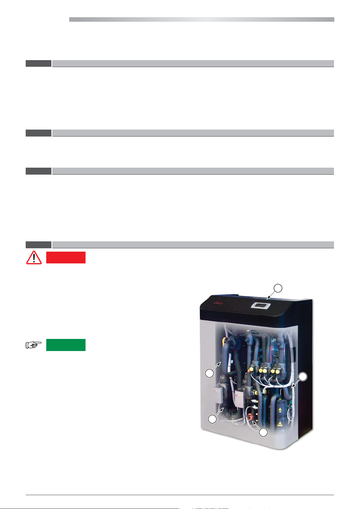
2.2.4 Residual risk areas
DANGER
Residual risk areas:
a Risk of short circuit and re.
b Risk of explosion due to the presence of pressurised
circuits.
c Risk of pollution due to the presence of refrigerant in the
circuit.
d Risk of burns due to the presence of hot surfaces.
WARNING
following:
a Use the electric panel in compliance with the
manufacturer's instructions. Do not place metal
objects inside the electric panel. Do not place
ammable substances near the unit.
b Do not alter any component of the cooling circuit and
do not operate the unit beyond the limits stipulated
by the manufacturer.
c Dispose of all the material that compose the unit
correctly and use suitable equipment to collect the
refrigerant gas (see Chap.10).
d Do not touch the internal components without
adequate safety devices during operation.
It has not been possible to eliminate certain residual risks during the design phase, found in
some areas of the unit, or protected with guards due to speci c features of the unit.
Each operator must be aware of the residual risks on this unit in order to prevent potential
accidents.
In order to prevent the abovementioned risks, it is very
important to comply with the
a
d
a
c
b
14
All copying, even partial, of this manual is strictly forbidden RG66007967 - Rev 02
Page 15
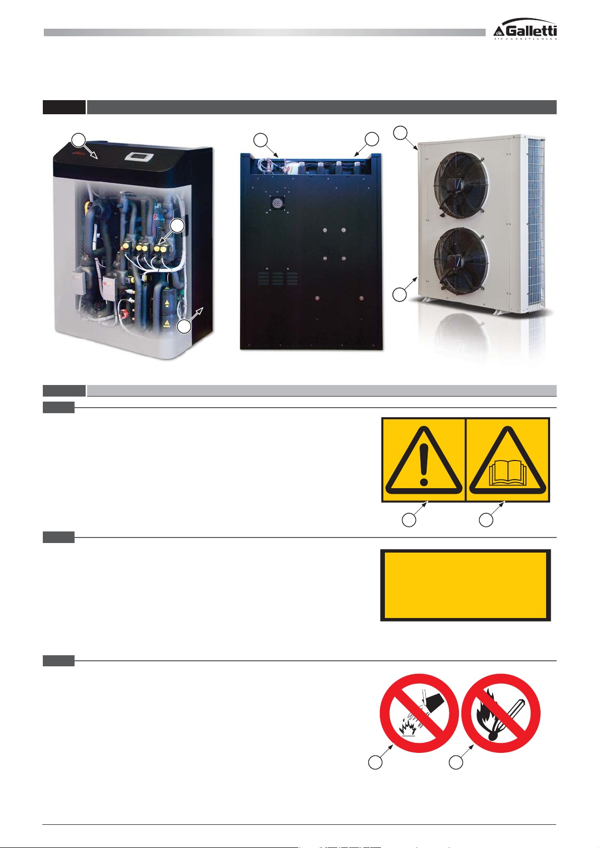
2.3 LOCATION OF THE SAFETY LABELS
1 3
5
4
2.3.1 Description of the safety labels
4
2
6
1
a Warning of danger due to the user not being aware of all the functions of
the unit and the consequent risks.
b Read the use and maintenance manual carefully before operating the unit.
2
Power supply label.
3
a Do not use water to extinguish re.
b Do not smoke and/or use open ames.
a
b
ALIMENTAZIONE ELETTRICA
POWER SUPPLY
SPG.VERSORGUNGSTEIL
400V/3/50Hz
a b
All copying, even partial, of this manual is strictly forbiddenRG66007967 - Rev 02
15
Page 16
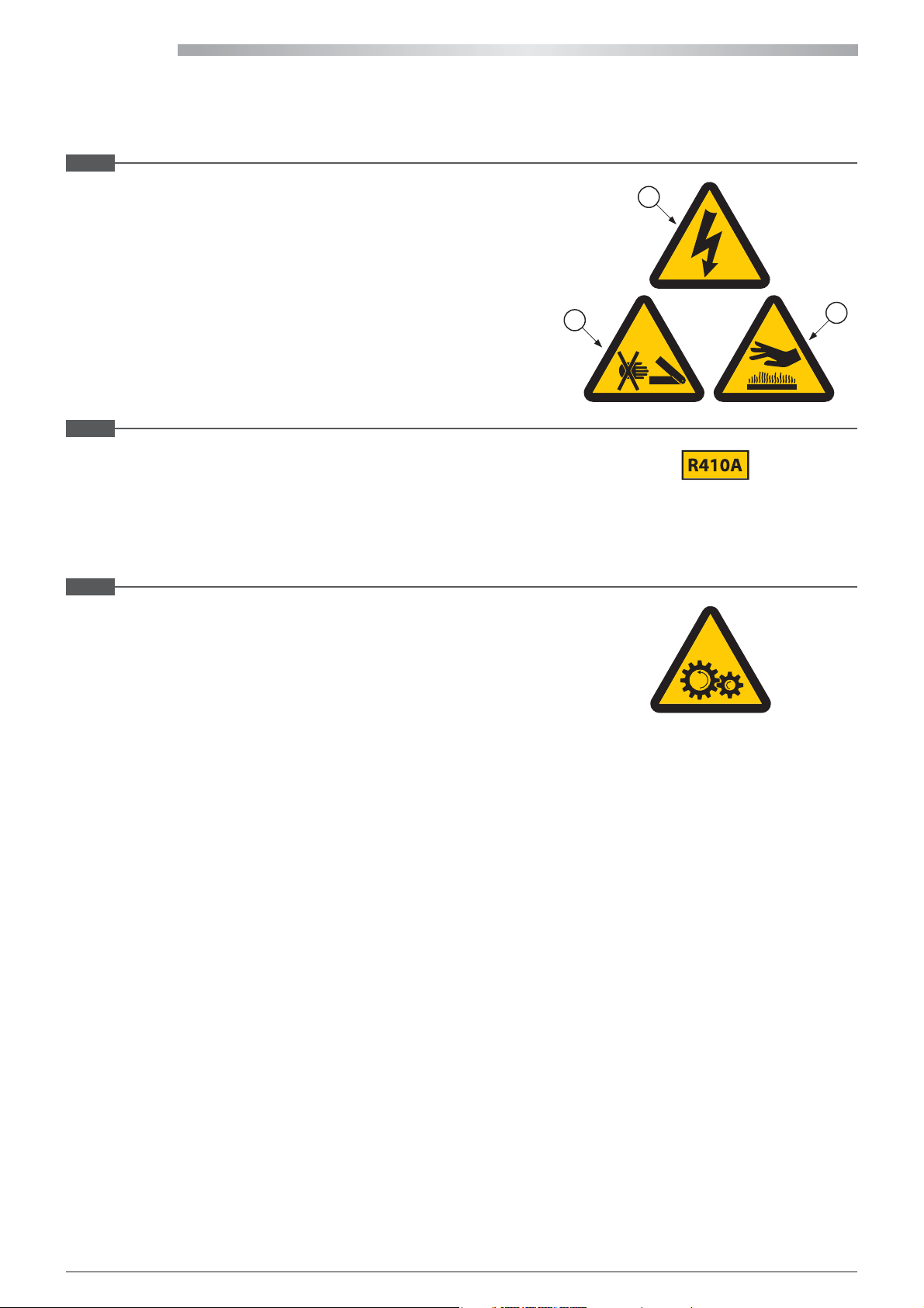
HIWARM
4
a Electric voltage hazard.
b Risk of shearing in the nned coil area.
c Risk of burns.
a
5
Liquid refrigerant.
6
Hazard: moving mechanical parts.
b
c
16
All copying, even partial, of this manual is strictly forbidden RG66007967 - Rev 02
Page 17
2.4 GENERAL SAFETY STANDARDS
2.4.1 Attention and maintenance
Many accidents and damage are caused due to maintenance errors, such as:
- no water in the circuit;
- incorrect percentage of refrigerant in the circuit;
- inadequate refrigerant;
- failure to keep the unit area clean;
- circuit ineciency (pipe connections, loose pipes, screws, etc.).
Maintenance must be performed carefully even for personal safety.
Never delay repairs.
Only specialised or authorised personnel must perform repairs.
Always comply with the following safety standards, even when you are completely familiar with all the operating elements:
- Always keep the unit and its surrounding area clean.
- Before starting work check that the safety devices are in perfect working condition.
- Make sure that no unqualied or unauthorised persons enter the unit area.
2.4.2 Fire extinguisher and rst aid
- Verify that the re extinguisher is in place.
- Periodically verify that the re extinguishers are loaded and all operators know how to use them.
- It is important to know where the rst aid kit is kept.
- Periodically verify that the rst aid kit is equipped with disinfectant, bandages, medicine, etc.
- It is important to know what to do in case of re.
- Make sure the emergency telephone numbers are readily available and nearby.
If a re breaks out, use the re extinguisher according to the relative regulations in force.
Contact the re brigade.
WARNING
The owner of the property where the unit is installed is responsible for providing the re
extinguisher.
All copying, even partial, of this manual is strictly forbiddenRG66007967 - Rev 02
17
Page 18
HIWARM
2.5 MAINTENANCE PRECAUTIONS
2.5.1 Tools
Personal injury is prevented by not using worn or damaged, low quality or makeshift tools.
ATTENTION
2.5.2 Personnel
Routine maintenance specied in this manual must only be performed by authorised and trained personnel.
Contact the MANUFACTURER for maintenance or repairs that is not specied in this manual.
2.5.3 Keeping the unit clean
Stains of oil and grease and scattered tools or broken parts are hazardous as persons can slip or fall. Always keep the unit
area clean and tidy.
Do not use diesel or petroleum to clean the unit as they leave an oily layer that increases dust adhesion, and neither solvents
must be used (even if weak) as they damage the paint and increase the formation of rust.
If a jet of water penetrates the electrical equipment the contacts oxidise and the unit can malfunction.
Therefore, do not use jets of water or steam on the sensors, connectors or any electrical part.
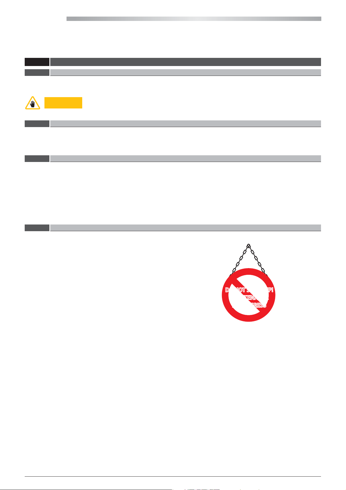
2.5.4 Warning signs
Switch the unit o before performing any maintenance.
Serious or fatal injury could be caused if other persons
start-up the unit and activate the control buttons while
maintenance is performed.
Warning signs must be placed around the unit before
performing any maintenance in order to prevent such risks.
The manufacturer cannot be held liable for damage caused if modied tools are used.
DO NOT START-UP!
MAINTENANCE
IN PROGRESS
18
All copying, even partial, of this manual is strictly forbidden RG66007967 - Rev 02
Page 19
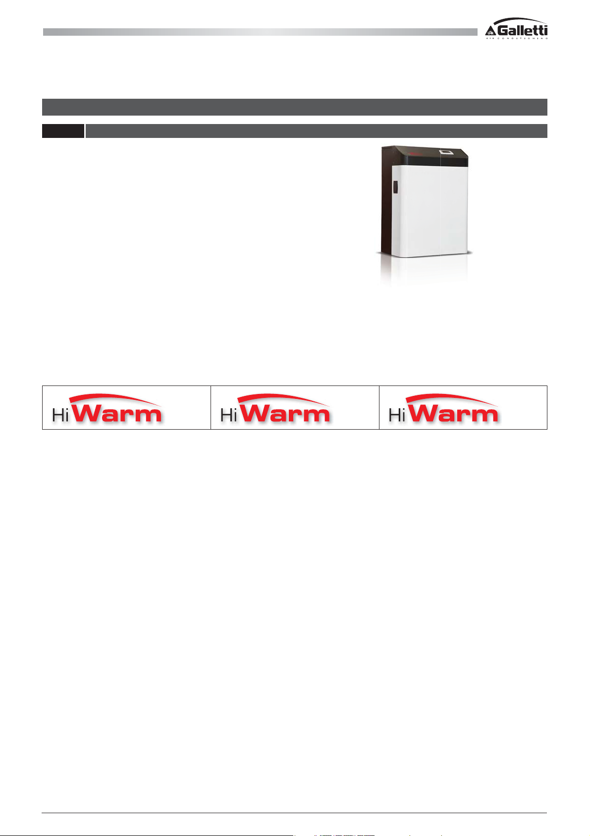
3 - DESCRIPTION OF THE PRODUCT
3.1 THE SERIES
HiWarm is a residential air-water multifunction heat
pump that absorbs cold or heat from the external air and
simultaneously, with no combustion or ame, warms or
cools the home and autonomously produces domestic hot
water, prioritised or total heat recovery in cooling mode.
The product is available in three sizes, classi ed according to
cooling capacity in nominal conditions, i.e. water produced
at 12 / 7°C with the external air at 35°C. The following
features are common in all three:
- Split unit with compressor mounted in the indoor
unit, thereby reducing the external noise emission and
allowing for a light outdoor unit, which can be positioned
at a height with simple brackets.
- Outdoor unit for indoor use, ductable, compact with backward-curved blade fans activated by an EC synchronous
permanent magnets motor, designed for attics.
- Expansion device: EEV (electronic expansion valve) to bene t from the possibility of generating thermodynamic cycles
under reduced pressure changes with signi cant COP advantages.
- Built-in pump control on system side and DHW side: both pumps are managed directly by the unit.
Three models can be chosen from, classi ed according to the maximum cooling capacity they can produce:
012 022 033
The dimensions of the indoor unit can be divided in two frame sizes, for each model:
Frame1
- HiWarm012: (LxHxD)= 803x1120x501.5 mm
rame2
F
- HiWarm022: (LxHxD)= 803x1247x606 mm
- HiWarm033: (LxHxD)= 803x1247x606 mm
he dimensions of the outdoor units with axial fans are di erent for each model:
T
Frame1
- HiWarm012: (LxHxD)= 1120x1230x450 mm
F
rame2
- HiWarm022: (LxHxD)= 1410x1280x450 mm
- HiWarm033: (LxHxD)= 2000x1512x550 mm
All copying, even partial, of this manual is strictly forbiddenRG66007967 - Rev 02
19
Page 20

HIWARM
Double water circuit:
- Air conditioning circuit with reversible cooling circuit side and variable set-point between min/max with potential-free
contact or with 0-10V or 4-20 mA signal.
- Total heat recovery (for simultaneous cooling) or in any case prioritised DHW circuit. This circuit is separate and does
not need long heating/cooling stages of inertial storage, like similar products on the market, which jeopardise energy
eciency especially during summer operation.
The basic selection when developing the range of multifunction units consists in using the following:
- Scroll or twin-rotary compressors.
- Brazed plates.
- High-eciency fans.
- Electronic expansion valve.
- AISI 316 Stainless steel high-eciency plate heat exchangers.
- Advanced electronic control allows load partialisation requirements to be adequately met.
For optimal partial load operation, which is ever more an object of evaluation and a discriminating factor in the technical
choice of heating technicians.
The structure of the HiWarm units has the following characteristics:
- Indoor unit:
side panelling in galvanised sheet metal painted with polyester epoxy powders and polymerised in the oven at 180°C and
a front cover that incorporates the Display, on two basic levels (LCD) and a 10” Graphic Touch Screen Windows CE. The unit
is fully panelled but can be accessed on 3 sides since the panels can be easily removed, thereby simplifying maintenance
and/or inspections. All routine maintenance is performed from the front of the unit.
- Outdoor unit:
side panelling in galvanised sheet metal painted with polyester powders and polymerised in the oven at 180°C. The unit is
totally faired and panelled and is available in RAL9002 (Grey White).
6-pole axial fans with blades having a high degree of overlapping, combined with asynchronous motors with an external
rotor (or synchronous with permanent magnets) and continuous modulation of the rotation speed.
- Remote unit for indoor installation (attic):
panelling in galvanised sheet metal painted with polyester powders and polymerised in the oven at 180°C. The unit is
totally faired and is available in RAL9002 (Grey White).
Radial fans with brushless motors are used, which are ideal for continuous and ecient modulation. Maximum head
available at 200 Pa.
The components are distributed to guarantee easy access and the layout ensures optimum weight distribution on the unit's
base.
20
All copying, even partial, of this manual is strictly forbidden RG66007967 - Rev 02
Page 21
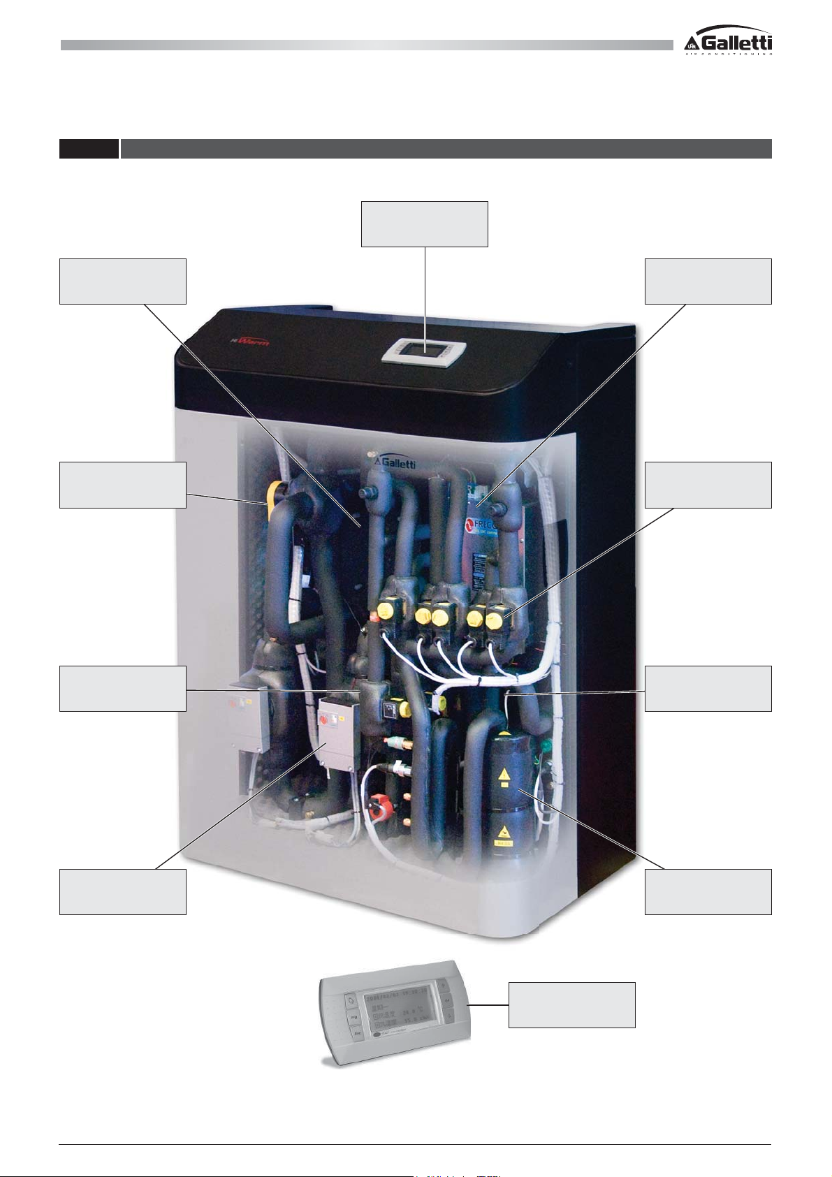
3.2 MAIN COMPONENTS OF THE INDOOR UNIT
DISPLAY
PLATE
HEAT EXCHANGERS
CYCLE INVERSION
VALV E
INVERTER
SOLENOID VALVES
LIQUID RECEIVER
PUMPS
LIQUID
SEPARATOR
COMPRESSOR
STANDARD
USER INTERFACE
All copying, even partial, of this manual is strictly forbiddenRG66007967 - Rev 02
21
Page 22
HIWARM
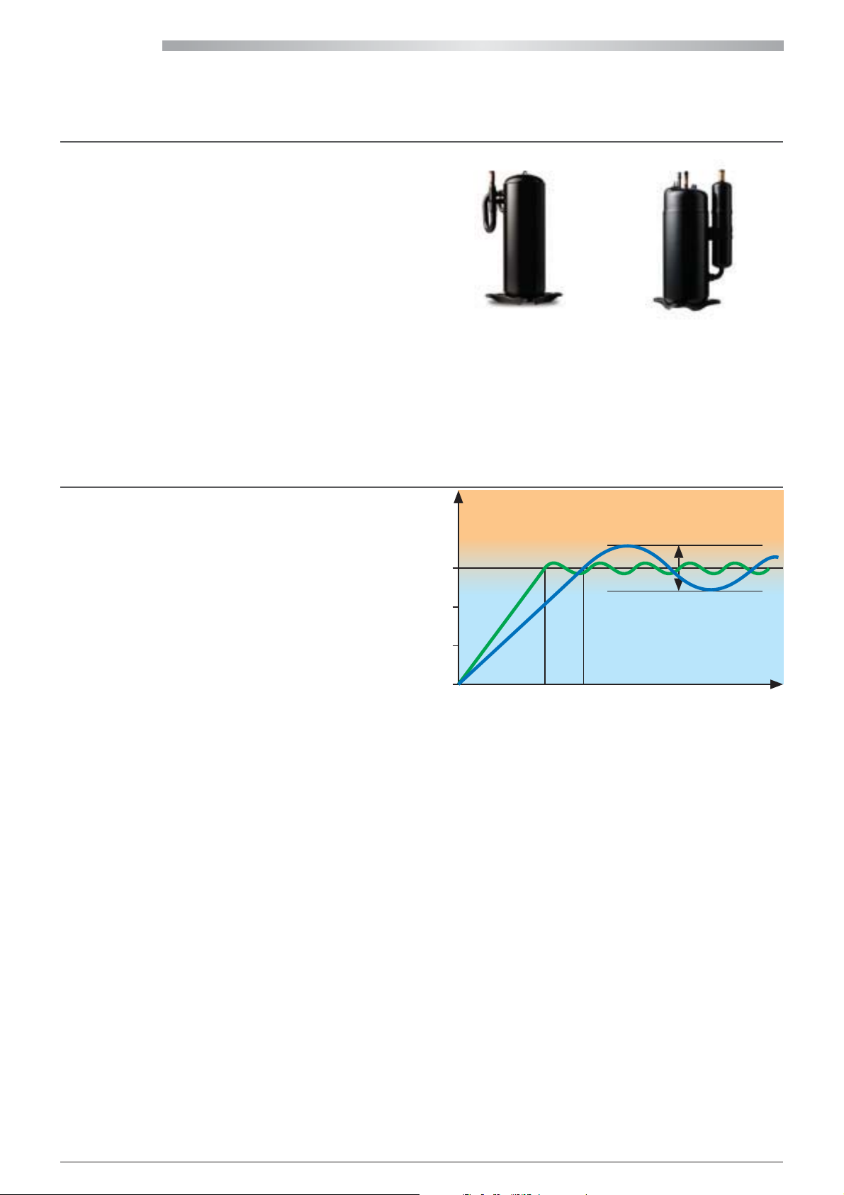
Scroll or Twin-Rotary R410A Compressors:
Processing optimisation together with a careful choice
of the intrinsic volumetric compression ratio (ICR) allows
for a signicant improvement in isentropic compression
performance and a consequent reduction in energy loss
during the process. Low viscosity oils can be used thanks to
the scroll and twin rotary compressor, which greatly reduce
evaporator thermal resistance, compared to high viscosity
oils, with an increase of over 1.5°C in the evaporation
temperature (over 5.5% in EER), with respect to alternative
solutions.
Hermetic orbiting Scroll compressors (HiWarm22 and
HiWarm33) or Twin Rotary compressors (HiWarm12) are complete with motor protection against over temperature,
overcurrents and excessive gas ow temperatures. Mounted on anti-vibration dampers, complete with oil charge and
inserted in a soundproof compartment with sound-absorbing material. Also complete with an automatically activated oil
heater to prevent the oil from being diluted by the refrigerant when the compressor stops.
The compressors have a brushless synchronous motor with permanent magnets, piloted by a driver with a trapezoidal wave
signal at a speed rate between 30 (20) and 120 Hz [BLDC Technology “Brush Less Direct Current”].
Inverter:
A static converter of electrical energy, that is a rectier and
an AC-DC AC converter. The function of the inverter is to
control the motor power supply during an actuation. From a
more general aspect, the inverters allow the amplitude and/
or frequency of the motor supply voltage to be changed.
It is required when brushless synchronous motors with
permanent magnets (BLDC) are used, in order to guarantee
motor operation.
The inverter compressor is driven with proportional
regulation and proportional plus integral regulation on the
set-point in any mode:
If a simultaneous request is made by the utility - cooling the
room and DHW for the system - the default set-point speed is determined by the minimum speed of the two. After the
initial start-up phase, the inverter modulates the performance of the motor in real time according to the demand of the
application, thereby supplying only the real power requested. Consequently, the frequency varies from a minimum value of
20 (30) [Hz] to a maximum of 120 [Hz] depending on the utility demand. The maximum acceleration is dened by the torque
limits that can be supplied as well as the need to minimise the amount of oil entrained into the transients and is a parameter
that cannot be modied.
20
15
10
5
Scroll Twin Rotary
INTERNAL TEMPERATURE °C
~3°C
MODEL WITH INVERTER
STANDARD MODEL
TIME
22
All copying, even partial, of this manual is strictly forbidden RG66007967 - Rev 02
Page 23
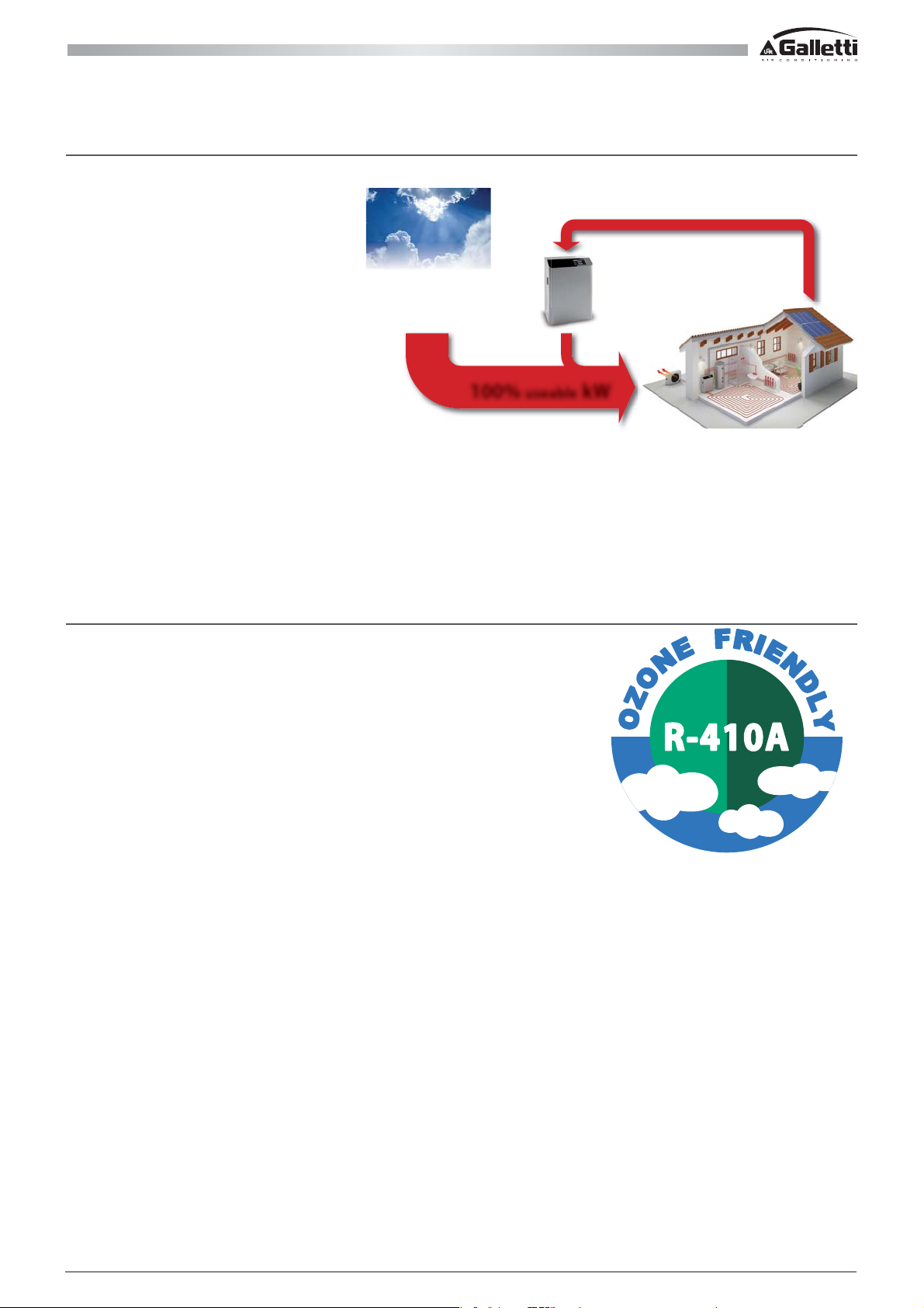
R410A refrigerant uid:
HFC R410A is distinguished by very
favourable thermal conductivity of the
liquid and negligible Glide, even if this results
in a higher GWP than other refrigerants
(Global Warming Potential GWP= 1975 kg
), which lead to signi cantly enhanced
CO
2
evaporation performance together
absorbed from the environment
with improved condenser performance.
80% energy
(renewable “clean” energy)
20% operating energy
(supplied by renewable
ovoltaic panels)
phot
The greater operating pressures and a
favourable pressure curve (temperature)
allow more compact thermal exchange
geometries to be used, which present a
100% useable kW
smaller internal volume compared to the
same exchange surface, and therefore
require less refrigerant charge: these factors lead to a reduction of the overall GWP of the unit compared to products with
other types of ecological refrigerants of the HFC family.
The GWP of R410A is 1,975 kg CO
against the 1,177 of R407C and 1,410 of R134a. This disadvantage is made up for with the
2
greater EER and even better ESEER. The GWP is greater than other HFC uids, but the TEWI (total equivalent warming impact)
is much less, thanks to the high e ciency and reduced refrigerant charge.
With an average increase of 8% in the surface, the internal volume of the coils is 23% less. The average density is in turn lower
and therefore the R410A charge is approximately 27% less than that of R407C units of the same size.
TEWI: Total Equivalent Warming Impact:
This expresses the mass of CO
that produces the same overall e ect as the
2
chiller during its operational life. The main feature of this parameter is based on
the e ects of using a refrigerant gas, which do not only derive from the possible
accidental emission into the atmosphere, but also the e ect on global warming
generated by the carbon dioxide emitted for energy to be produced to operate
the chiller in question. The TEWI is de ned as the sum of the direct and indirect
e ect:
TEWI= α
· E + GWP · m
CO2
ref
t&FOFSHZDPOTVNFECZUIFDIJMMFSEVSJOHJUTPQFSBUJPOBMMJGF
tȺ
= amount of carbon dioxide emitted to produce one kWh of
CO2
electrical energy, and which depends on how it is generated.
= refrigerant charge.
tN
ref
In order to assess the TEWI, it is therefore necessary to estimate the e ciency of the chillers from which the energy
consumption, their life, the type of energy source from which it is drawn and the mass of refrigerant contained depend.
Besides the control of emissions into the atmosphere and the choice of environment-compatible refrigerants, this type
of approach also focuses on improving the overall e ciency of the chiller, which can play an important role on the actual
impact that a uid has on global warming, depending on the applications.
All copying, even partial, of this manual is strictly forbiddenRG66007967 - Rev 02
23
Page 24
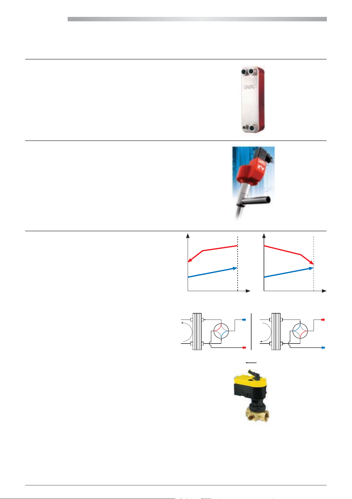
HIWARM
T
AISI 316 Stainless Steel Plate Heat Exchangers:
The thorough study of internal corrugation maximizes
turbulence (heat exchange coecient), thereby minimising
the possibility of fouling. In line with the powers involved,
it is always recommended to choose the maximum thermal
length in order to have the maximum benets possible from
the countercurrent ows.
Electronic expansion valve (EEV):
Installed as per standard on all HiWarm units. If congured
correctly and controlled properly by the software, this
device helps the cooling circuit be highly ecient and this
will thereby reduce the power absorbed by the system The
shutter in the central part of the valve slides vertically with
an ample stroke, thereby allowing a vast variation in the
opening of the uid passage orice.
This valve allows for reduced energy consumption of the
compressor.
4-way cycle inversion valve:
Thanks to the principles of Thermodynamics, it is a known
fact that heat exchange is more ecient when this occurs in
countercurrent rather than cocurrent.
Most of the reversible units congured as cocurrent after
switching from Cooling mode to Heating mode, with a
consequent reduction in thermodynamic performance.
By inserting a 4-way valve on the utility water circuit (indoor
unit) the water ow direction can be inverted on the heat
exchanger according to the inversion of the refrigerant ow,
thereby maintaining the countercurrent. Of course, the
water direction to/from the system does not change.
The utility side water connections keep the same IN/OUT
conguration and the user does not notice any change.
N.B.: the above-mentioned selection always considers a
heat exchange in countercurrent mode.
T
R
Countercurrent Cocurrent
POS.A
R
cooling
user
POS.A POS.B
R
heating
R
POS.B
user
24
All copying, even partial, of this manual is strictly forbidden RG66007967 - Rev 02
Page 25
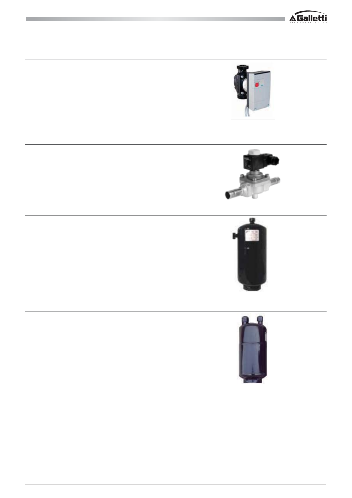
Pumps:
Energy class A, electronically-controlled, maintenance-free,
high eciency, wet rotor circulation pumps are used with
EC motors. The pump body is made of grey cast iron with
a cataphoresis KTL nish, which is an excellent protection
against corrosion. The thermal insulation is made of
polypropylene, the shaft is made of stainless steel, the
bearings are made of metal-impregnated carbon, and the
impeller with a three-dimensional coil is made of synthetic
material with a carbon bre hermetic insulation coating.
Solenoid valves:
Solenoid valves are widely used to control the ow of hot/
cold liquids with on/o-type utilities. The principle of
operation consists of an electrical current being applied to
a coil that creates a magnetic eld. This is transformed into
mechanical energy, which opens or closes the valve. The
principle of operation is very reliable, inexpensive and widely
used for each type of application with ON/OFF utilities.
Liquid receiver:
The unit is modulating with variable ows and possible
operating conditions that may dier. The optimal refrigerant
charge depends on the volumes of the heat exchangers and
the points mentioned and can therefore vary signicantly
in the various operating modes. The liquid receiver is
therefore important to restore equilibrium, especially during
transitions.
Liquid separator:
The liquid separator is placed on the compressor intake line
and has the function of containing the excess refrigerant
that has not evaporated and prevent it from returning to
the compressor in its liquid state, thereby preventing any
damage this could cause.
All copying, even partial, of this manual is strictly forbiddenRG66007967 - Rev 02
25
Page 26
HIWARM
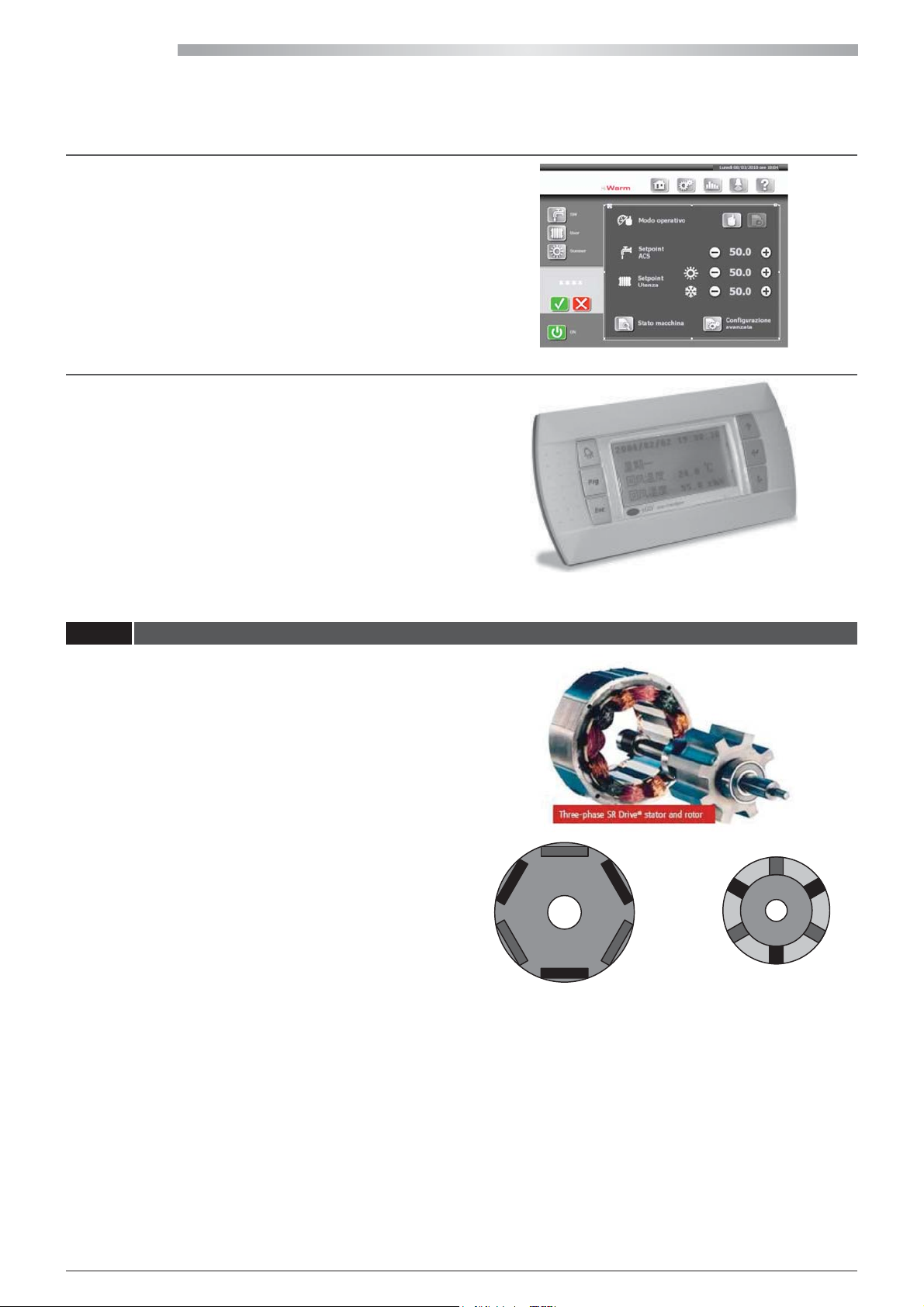
Touch Screen Display:
Possibility of 10.4” Touch Screen Display with WINDOWS CE®
operating system.
User interface:
The user interface, PGD1, consists of an LCD display (8 rows x
22 columns) and 6 keys.
All the program operations can be run, the conditions of
the operating unit can be displayed at any time and the
parameters can be modied.
3.3 SYNCHRONOUS MOTORS
Our compressors and hydraulic pumps use BLDC synchronous
electric motors (Brushless Direct Current). Synchronous
motors are distinguished by a constant of rotation regardless
of the load (or torque) but related to the denite frequency
of the inverter.
The Brushless synchronous motor has no brushes as the
power is only sent to the stator and not directly to the rotor,
therefore, sliding electrical contacts are not required. Over 20
Hz, the mP on board controls a feedback signal (BEFM Back
Electro Motive Force) that can certify the rotor's synchronous
rotation with a magnetic eld and implements any torque
corrections to restore/maintain synchronism and therefore
maximum eciency.
- The BLDC does not require induction in the stator windings
(there already is a permanent magnet in the rotor) =>
There are no relative losses.
- The BLDC has no rotor currents (due to the stator induction
of the asynchronous motors) => No rotor loss.
- The BLDC has no sliding contacts => No maintenance. The
position of the rotor is detected by measuring the BEFM
(back electro motive force), caused by the rotor during
the non-energised phase (when one of the three passage
phases is zero): there are no Hall eect sensors in the motor
due to their unreliability at high speed and temperature
and therefore the motor is also called “sensorless”.
N
SS
NN
S
SS
NN
Stator Rotor
N
S
26
All copying, even partial, of this manual is strictly forbidden RG66007967 - Rev 02
Page 27
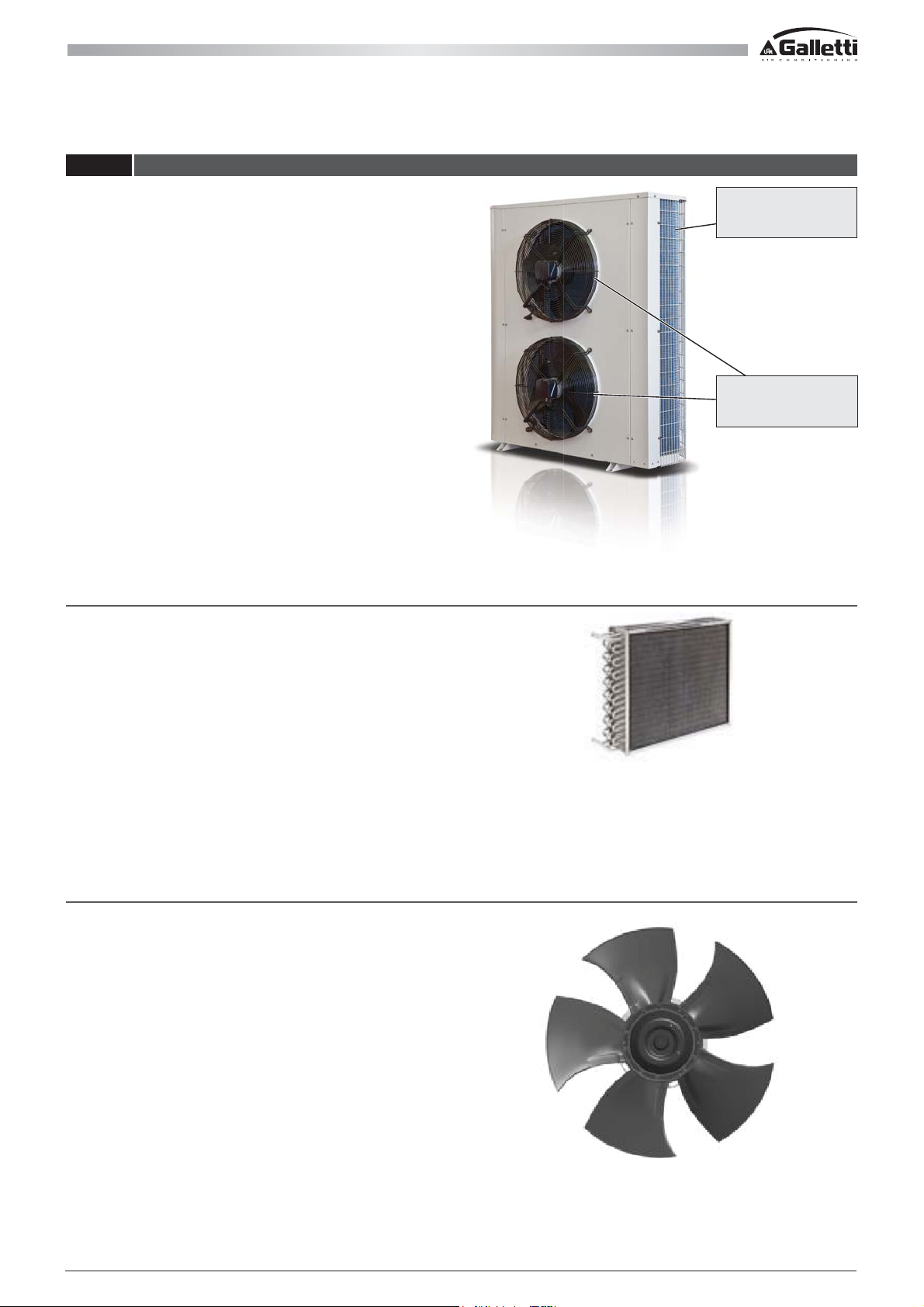
3.4 MAIN COMPONENTS OF THE OUTDOOR UNIT
The outdoor unit has the same components in all three sizes.
The size of the nned coil changes together with the number
of fans that increase by one unit as the size increases (two
fans for the 012, three for the 022 and four for the 033).
Finned pack heat exchangers:
The nned pack heat exchangers allow for the maximum
front surface in relation to the footprint of the unit. The
wide front surfaces reduce the risk of fouling and thanks to
the reduced through-speed the air-side pressure drops are
reduced, which bene ts the air ow rate (e ciency) and the
emitted sound power of the fans. Heat exchange between
the refrigerant and air takes place thanks to a number of 25 x
21.65 mm expanded pipes (8 mm diameter), in an automatic
and controlled process, in 0.10 mm thick aluminium
ns. Expansion is a fey factor and important process as it
determines the pipe/ n contact resistance and it is often
ignored in the case of high heat exchange e ciencies.
FINNED PACK
HEAT EXCHANGERS
FANS
Fans:
6-pole fans are used in the outdoor remote unit (3 pole pairs ),
with plastic blades having a high degree of overlapping (450
mm), combined with single-phase asynchronous motors or
alternatively, synchronous with EC permanent magnets.
With regards to the remote unit for indoor use, enhanced
silence is obtained by using centrifugal fans with backwardcurved blades with a strong degree of reaction combined
with EC brushless motors for continuous and e cient
modulation: the air ow rate and therefore the absorbed
power and noise emitted are always adapted to the actual
conditions of use in terms of pressure drops of the channels
and degree of capacity control of the unit.
All copying, even partial, of this manual is strictly forbiddenRG66007967 - Rev 02
27
Page 28
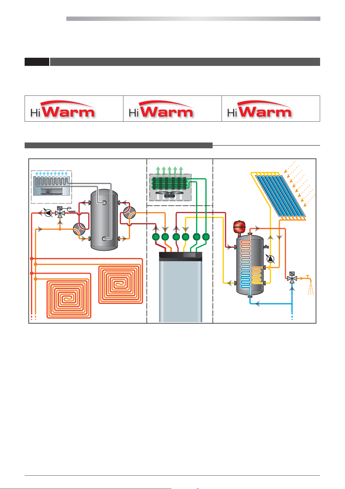
HIWARM
3.5 RANGE AND OPERATION
HiWarm is a multifunction residential air-water heat pump that can autonomously satisfy all the heating and cooling
requirements throughout the year, with no fossil fuels.
Three models can be chosen from, classi ed according to the maximum cooling capacity they can produce:
012 022 033
HiWarm has four di erent operating modes:
Priority production of domestic hot water alternated with environmental heating.
REMOTE UNIT DOMESTIC HOT WATERHOME ENVIRONMENT
Fan coil
Storage tank
Flooring
A B FEC D
Storage tank
Water mains
Domestic hot
wate
r
28
All copying, even partial, of this manual is strictly forbidden RG66007967 - Rev 02
Page 29
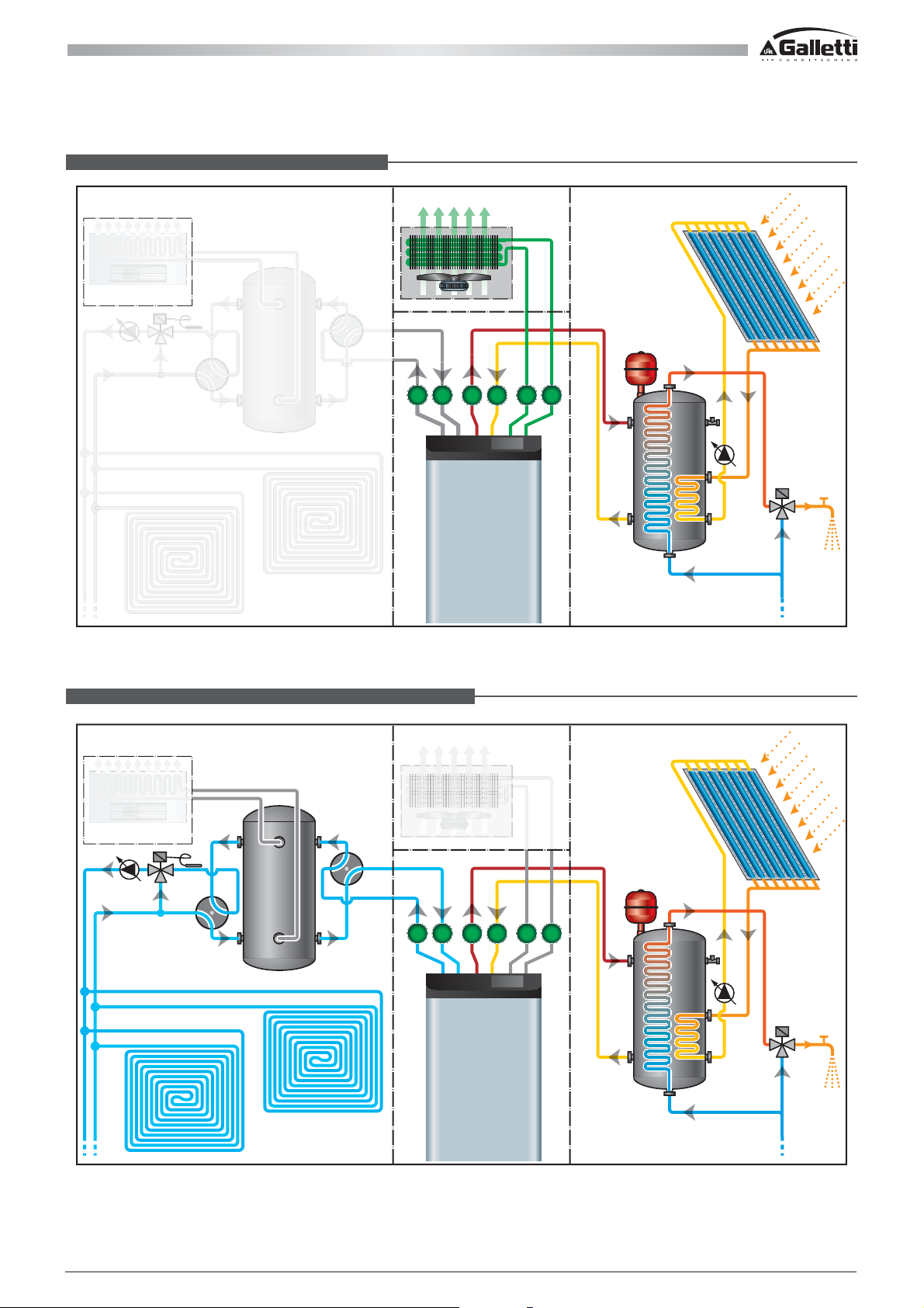
Production of domestic hot water only.
Fan coil
HOME ENVIRONMENT
Storage tank
Flooring
REMOTE UNIT
A B FEC D
DOMESTIC HOT WATER
Storage tank
Domestic hot
water
Water mains
Cooling and simultaneous production of domestic hot water.
HOME ENVIRONMENT
Fan coil
Storage tank
Flooring
REMOTE UNIT
A B FEC D
DOMESTIC HOT WATER
Storage tank
Domestic hot
water
Water mains
All copying, even partial, of this manual is strictly forbiddenRG66007967 - Rev 02
29
Page 30
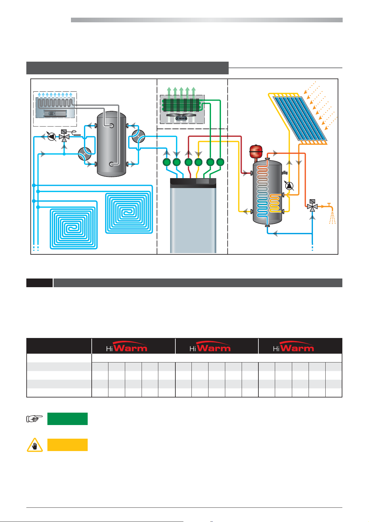
HIWARM
Cooling, dehumidication and simultaneous production of domestic hot water,
alternated with excess heat dissipation to the coil.
REMOTE UNIT DOMESTIC HOT WATERHOME ENVIRONMENT
Fan coil
A B FEC D
Storage tank
Storage tank
Flooring
Water mains
Domestic hot
water
3.6 PIPING AND LOAD DESIGN CRITERIA
All the copper pipes are made according to our specications for the construction process to be fully controlled and implicitly
improve the quality of our products. Each pipeline complies with the requirements of Directive 97/23PED and is veried by
FEM code at the most stressed 180° bending point and at the maximum pressure allowed by the safety components while
also considering adequate safety coecients.
The tables below provide guidelines regarding the pipes to use to connect the indoor and the outdoor units according to the
dierent sizes of the HiWarm and the length of the line:
Model
Refrigerant R410A
Pipe length m
Compressor frequency Hz
Intake line (GAS) mm-in
Liquid line mm-in
0-5 6-10 11-15 16-20 21-25 0-5 6-10 11-15 16-20 21-25 0-5 6-10 11-15 16-20 21-25
30-120 30-120 30-120 30-120 30-120 20-120 20-120 20-120 20-120 20-120 20-120 20-120 20-120 20-120 20-120
16-5/8" 16-5/8" 16-5/8" 18-3/4" 18-3/4" 18-3/4" 18-3/4" 18-3/4" 22-7/8" 22-7/8" 22-7/8" 22-7/8" 22-7/8"
10-3/8" 10-3/8" 10-3/8" 10-3/8" 10-3/8" 12-1/2" 12-1/2" 12-1/2" 12-1/2" 12-1/2" 16-5/8" 16-5/8" 16-5/8" 16-5/8" 16-5/8"
012
022
033
28-1 1/8" 28-1 1/8"
WARNING
ATTENTION
Use pipes marked in compliance with standard UNI 12735.
The connection gas/liquid lines between the indoor and outdoor units must be vacuumed
before opening the valves of the indoor unit. The absence of air and moisture in the pipes
is important in order to guarantee proper operation and durability of the unit. Qualied
personnel must install the pipes and perform the installation.
30
All copying, even partial, of this manual is strictly forbidden RG66007967 - Rev 02
Page 31
The unit is pre-charged with R410A before leaving the factory, however, the charge must be veried during the start-up
phase.
WARNING
Since R410A is a binary blend of R32 and R125, it is advisable to charge with refrigerant in the liquid
phase to ensure the correct percentage of the 2 components.
Charge through the charging inlet provided between the expansion valve and evaporator inlet.
ATTENTION
WARNING
A unit that was originally charged with R410A in the factory cannot be charged with other
refrigerants.
It is recommended to read the safety data sheet (MSDS) before using R-410A (see Chapter 12).
TOXICITY: R-410A can be safely used in all applications for which it is intended, according to
the processed data of the “Program for Alternative Fluorocarbon Toxicity Testing” (PAFT1).
LEAKS: the area must be immediately evacuated if there is a constant leak of R-410A gas.
The gases concentrate near the oor, thereby restricting the availability of oxygen. Once
evacuated, the area must be ventilated with fans or blowers in order to circulate the air at
oor level.
FLAMMABILITY: according to the 34 ASHRAE Standard, R-410A is classied in safety group
A1, i.e. it is not ammable at 1 atm of pressure (101.3 kPa) and 18°C.
CATEGORY: the refrigerant is a non hazardous category II uid.
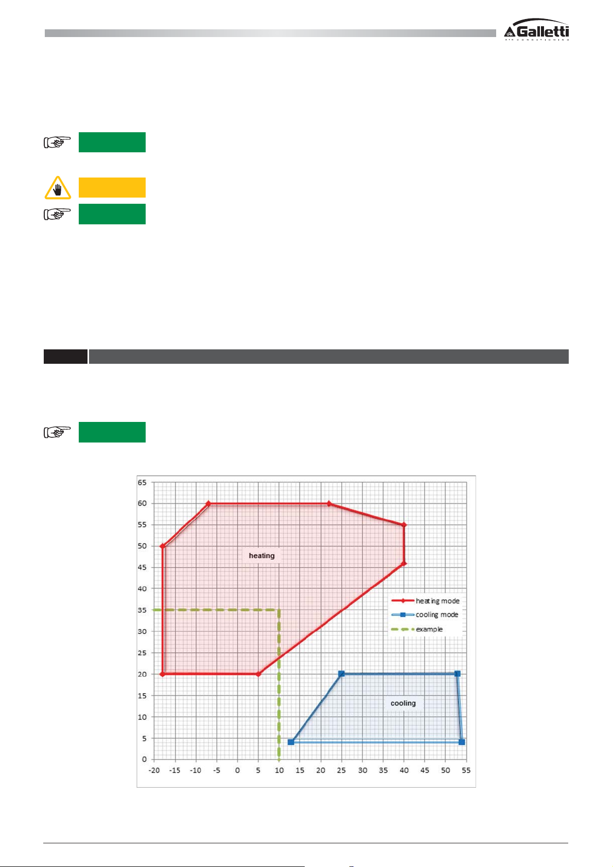
3.7 OPERATING LIMITS
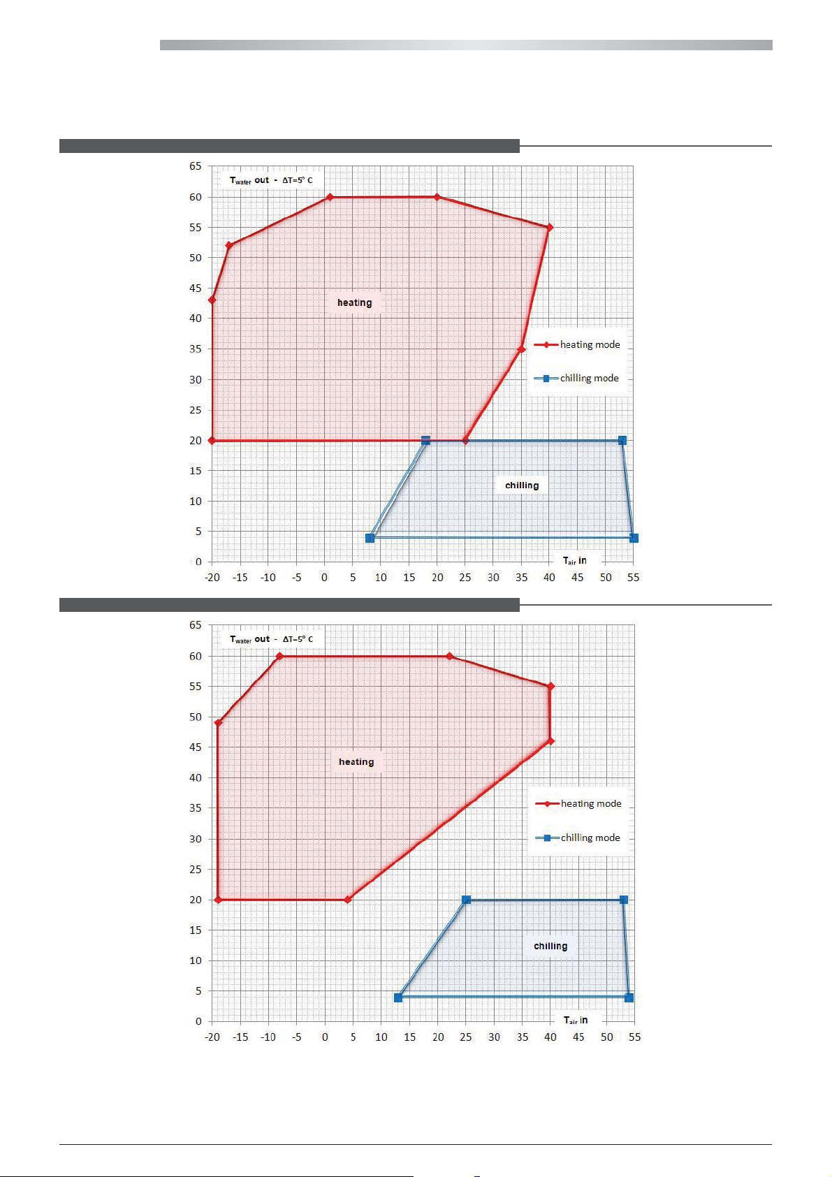
The diagrams below indicate the operating limits of the units and the ow temperature that the unit can supply according
to the outdoor temperature can be obtained.
The example in the graph below shows that the unit can obtain a ow temperature of 35°C up to a maximum of 60°C with
an outdoor temperature of 10°C.
WARNING
All the temperatures on the perimeter of the operating areas can only be reached as transients
and if the unit runs beyond these limits for a prolonged time, the software on board will
implement corrective actions to restore the unit within the operating limits.
All copying, even partial, of this manual is strictly forbiddenRG66007967 - Rev 02
31
Page 32
HIWARM
HiWarm 12 operating limits for the following produced water and outdoor air temperature:
HiWarm 22 operating limits for the following produced water and outdoor air temperature:
32
All copying, even partial, of this manual is strictly forbidden RG66007967 - Rev 02
Page 33
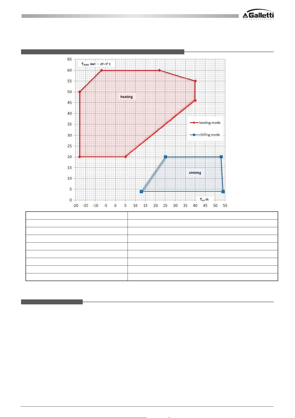
HiWarm 33 operating limits for the following produced water and outdoor air temperature:
Heat transfer uid: water or mixture of water and max 30% glycol anti-freeze
Maximum water side pressure: 5 bar
Maximum pressure on high pressure side 41.5 bar-r
Maximum ambient Temp of the indoor unit 42°C
Minimum ambient Temp of the indoor unit -10°C
Maximum pressure on low pressure side 29 bar-r (*)
Power supply voltage: +/- 10% compared to the voltage on the plate.
Maximum storage Temp of the indoor unit +42°C
Minimum storage Temp -20°C (limit determined by on board electronics)
(*) This value can only be reached during storage and determines the saturation pressure of 30 bar-r of the refrigerant on the
low pressure side of the circuit, which actually denes the limits.
Water ow to evaporator
The nominal ow rate refers to a temperature dierential of 5°C between inlet and outlet water, in relation to the cooling
capacity provided at the nominal water temperatures (12/7°C).
The maximum ow rate allowed is that associated with a temperature dierential of 3°C. higher ow rates cause high
pressure drops.
The minimum ow rate allowed is that associated with a temperature dierential of 8°C. lower ow rates could cause
excessively low evaporation temperatures, which could trigger the safety devices and stop the unit, or cause incorrect
distribution and risk of heat transfer with non-turbulent or not fully turbulent motion conditions.
All copying, even partial, of this manual is strictly forbiddenRG66007967 - Rev 02
33
Page 34
HIWARM
4 - INSPECTION, TRANSPORT AND POSITIONING
4.1 INSPECTION
Upon receiving the unit, verify its integrity: the unit left the factory in perfect conditions; report any damage to the carrier
immediately and write them on the Delivery Note before signing it. In particular, check that the ns of the nned pack heat
exchangers are not bent and have not been subject to any impact that could aect the tightness of the pressurised system.
The manufacturer or its agent must be promptly notied of the extent of the damage.
The Customer must submit a written report describing every signicant sign of damage.
- Commissioning report,
- wiring diagram,
- warranty certicate and list of service centres,
- check the integrity of the documents accompanying the unit and of this manual.
4.2 LIFTING AND CONVEYANCE
While the unit is being unloaded and positioned, utmost care must be taken to avoid abrupt or violent manoeuvres. The
internal movement must be implemented carefully and gently; do not use the unit components as anchors.
ATTENTION
In all lifting operations make sure that the unit is securely anchored in order to prevent
accidental falls or overturning.
Do not move or lift the unit from the removable front panel.
4.3 UNPACKING
The packaging must be carefully removed to prevent damaging the unit. The packaging consists of various materials: wood,
cardboard, nylon, etc.
It is recommended to store them separately and hand them over to suitable waste disposal or recycling facilities in order to
minimise their environmental impact.
4.4 POSITIONING AND INSTALLATION
Pay attention to the following aspects when choosing the best place to install the unit and the relative connections:
- size and origin of water pipes;
- location of power supply;
- access for maintenance or repairs;
- stability of the supporting surface;
- the application limits of the unit, which are:
Maximum (ambient) temperature °C 42
Minimum (ambient) temperature °C -15
Maximum (storage) temperature °C 42
Minimum (storage) temperature °C -20
ATTENTION
ATTENTION
The indoor unit has a protection degree of IP22 that does not allow it to be installed outdoors.
Make sure the unit is not exposed to much dust and protect it from humidity and salt spray. It
is mandatory to use the anti-vibration mounts supplied.
The fan unit is designed for outdoor use and must be positioned with care. The unit must be
fastened from the pre-set slots or holes and it is mandatory to to interpose the anti-vibration
mounts supplied.
The spaces indicated in the dimensional drawings must be complied with for the units to
function properly and routine maintenance to be performed.
WARNING
34
When the machine is in heat pump mode, ice could be formed on the outdoor unit in particular
climatic conditions. This is the result of standard operation of the unit.
When this occurs, the machine will automatically activate the defrosting function to eliminate
the ice and to restore ideal operation of the unit.
All copying, even partial, of this manual is strictly forbidden RG66007967 - Rev 02
Page 35
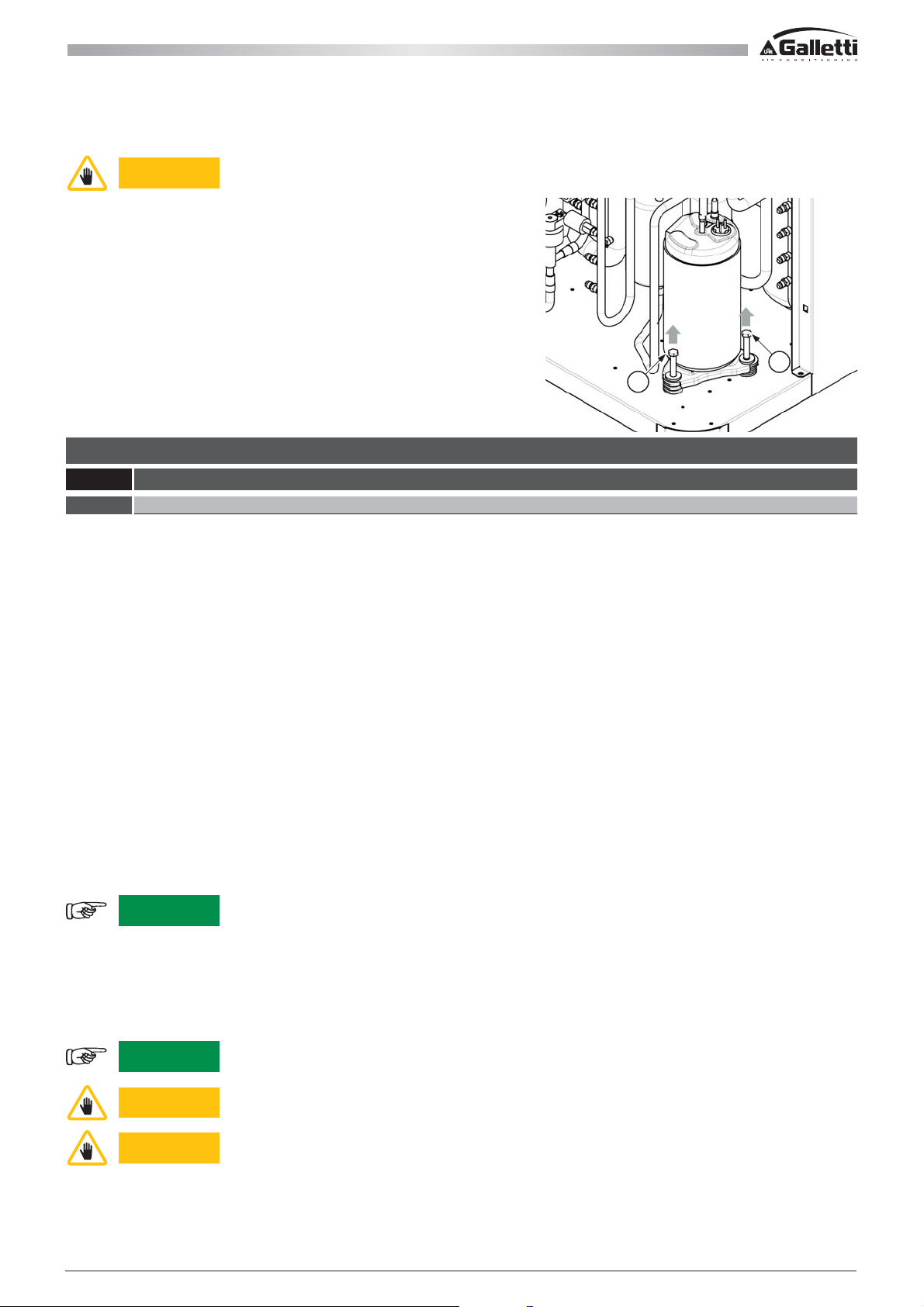
ATTENTION
Before starting is required to remove the xing screws (a) of the compressor which have to
block the compressor during transport.
a
a
5 - CONNECTIONS
5.1 WATER CONNECTIONS
5.1.1 General guidelines for the water connections
It is mandatory to follow the requirements below when preparing to set up the water circuit for the evaporator and in any
case national or local Standards must be complied with (refer to the diagrams attached to this document). Connect the
pipes to the chiller using exible couplings to prevent the transmission of vibrations and compensate for thermal
expansion. Refer to the technical data table for the type and dimensions of the hydraulic connections.
It is recommended to install the following components on the piping:
- temperature and pressure indicators for routine maintenance and inspections of the unit. Pressure control on the water
side allows the correct functionality of the expansion tank to be veried and any water leaks in the system to be detected
in advance;
- sumps on inlet and outlet piping for temperature detection, for a direct view of operating temperatures. They can also be
viewed on the display on board the unit (if pCO),
- shut-o valves (gate valves) to isolate the unit from the water circuit for maintenance purposes;
- metal net lter (inlet pipe) with a mesh that does not exceed 1 mm, to protect the heat exchanger from slag or
impurities inside the pipes. This requirement is especially important for commissioning;
- air vent valves, placed on the higher parts of the water circuit to bleed the air. The internal pipes of the unit are tted with
manual air vent valves to bleed the unit: this operation is to be performed when the unit is disconnected from the
power supply;
- a drain cock and where necessary, a drain tank, to empty the system for maintenance purposes or seasonal breaks;
- It is recommended to install a decoupling heat exchanger in process applications to prevent fouling in the heat exchangers,
which is likely to occur.
WARNING
Otherwise, the evaporator would be exposed to the risk of freezing since the anti-freeze thermostat would not be able to
perform its function and moreover, the countercurrent circulation would not be activated in the cooling mode, resulting in
additional risk of malfunction. This position does not enable consent by the water ow control device.
The dimensions and position of the water connections are provided in the dimensional tables and overview drawings.
WARNING
ATTENTION
ATTENTION
It is extremely important that the water inlet corresponds with the connection marked with
the writing “Water Inlet”.
The hydraulic circuit must be implemented in a way that guarantees a constant nominal ow
rate of water (+/- 15%) to the evaporator in every operating condition.
Never perform hydraulic connection operations with open ames near or inside the unit.
Make sure the intake pressure of the pump is always greater than 0.5 bar while the pump is
operating: this helps reduce the risk of cavitation.
All copying, even partial, of this manual is strictly forbiddenRG66007967 - Rev 02
35
Page 36
HIWARM
It is extremely important that the installer follows and veri es the following procedure step by step in order to prevent the
risk of tank implosion or pump cavitation:
- Drain the expansion tank in the system until the pressure reaches 0.5 bar.
- Fill the system and pressurise it to approximately + 1 bar in pump suction (pump stopped).
- Bleed the system.
- Check the pump suction pressure (approximately 1 bar) and start-up the system.
- Stop the pump after 15-30 minutes and repeat the procedure from step 3 until no more noise is heard due to air in the
system.
DRAINING THE SYSTEM
Drain outlets must always be set-up in the lower parts of the system. Drain the unit from the connections on the water pipes
beneath the pumps.
5.1.2 Technical data of the hydraulic pumps
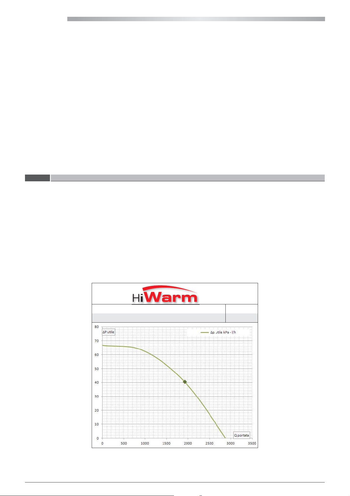
Two pumps are used in HiWarm: one for the utility, for heating or cooling, and one for domestic hot water. The relative pump
is activated according to the request.
The pumps installed are high-e ciency type with an inverter driven synchronous motor and fall under energy class A.
Common synchronous motor pumps have a characteristic curve that changes according to the pressure drops that occur.
The operating speed and therefore the ow rate are set by the system.
Asynchronous motor pumps have a characteristic curve that is controlled by the unit control microprocessor. The operating
logic can be at constant ow rate, constant head or according to the temperature in the heat exchanger.
Nominal useful head of the hydraulic pumps in cooling conditions: water 12/7°C and air 35°C. Inverter driven pumps can run
within the limited range over the characteristic range of the pump.
012
Absorbed power (kW) 0.1
Absorbed current (A) 0.6
36
All copying, even partial, of this manual is strictly forbidden RG66007967 - Rev 02
Page 37
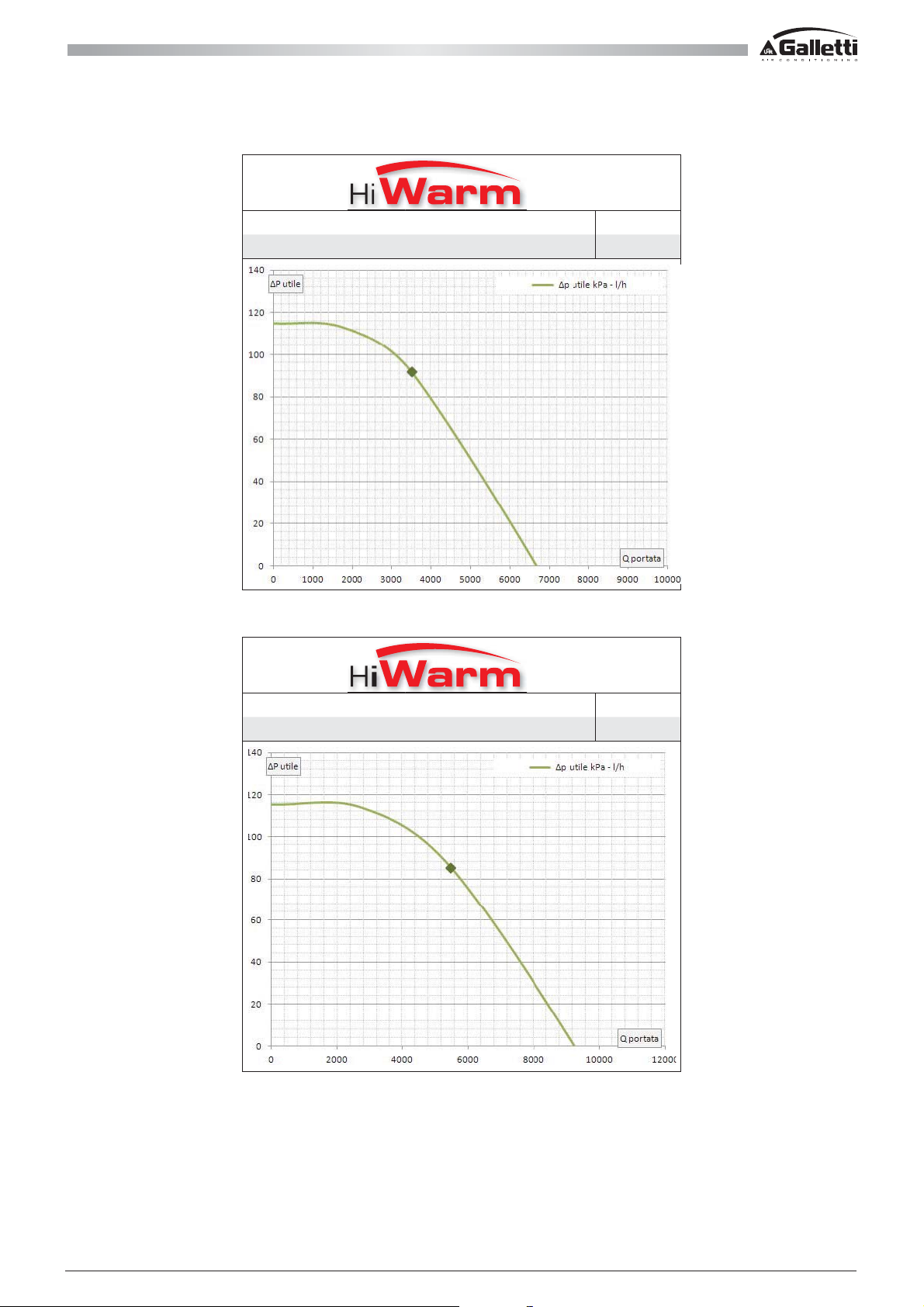
022
Absorbed power (kW) 0.3
Absorbed current (A) 1.3
033
Absorbed power (kW) 0.3
Absorbed current (A) 1.3
All copying, even partial, of this manual is strictly forbiddenRG66007967 - Rev 02
37
Page 38

HIWARM
5.2 ELECTRICAL CONNECTIONS
The electric connections must be set up by qualied sta. All connections must comply with the regulations enforced in the
country of installation. A suitable cutting-o device must be set up upstream of the electrical supply for the internal unit,
taking into consideration the electrical absorptions indicated in this manual and on the data plate. The user is also reminded
that the power supply to the external unit is supplied by the internal unit. The connection must be set up according to the
directions provided by the electrical diagram.
The protection to be installed up stream and therefore the size of the power supply cables depend on the electrical absorption
of the machine.
The following table indicates the maximum absorptions of the internal unit + external unit and are divided based on the type
of fan unit. Lastly, it is possible to nd the minimum recommended protection:
POWER SUPPLY HWO/HWD FANS
HIWARM
12 230
22 400 50 10,7 23 10,4 22 12,3 24 32
33 400 50 15,9 33,2 15,4 31,8 17,8 32,9 40
Voltage Frequency Phase chopping ELECTRONIC EC Ductable
[V] [Hz] P [kW] I [A] P [kW] I [A] P [kW] I [A] [A]
50 5 21,8 4,8 21,2 5,5 24,1 32
WARNING
The minimum indicated protection can be provided using gG type fuses or C curve magneto
thermal automatic switches.
For the correct sizing of the cable it is necessary to take into account (standard reference IEC EN60204-1):
1 The selected upstream protection.
2 Installation conditions.
3 Type of cable.
4 Maximum cable length.
The following table provides an example of sizing in the following hypothetical situations:
1 Maximum ambient temperature of 40°C.
2 Placement inside empty pipes.
3 PVC cable with a maximum operating temperature of 70°C.
4 Protection upstream, as per the previous table.
5 Multipolar cable.
MINIMUM
PROTECTION
POWER SUPPLY CABLE
MAIN PROTECTION
CABLE SIZE MAXIMUM LENGTH
[A] [mm²] [m]
32
40 10 99
50 16 114
6 84
The maximum length guarantees a lower voltage drop than required by regulation.
38
All copying, even partial, of this manual is strictly forbidden RG66007967 - Rev 02
Page 39
Regarding the dierential protection that needs to be installed upstream, it is necessary to use a type B switch that is sensitive
to direct currents. It is also preferable for it to have the following features:
1 Calibratable operation threshold.
2 Calibratable operation delay.
3 Dedicated exclusively to the heat pump.
Below is a list of the recommenced cable sizes to be used for the connection between the internal and external unit, for a
maximum distance of 30m:
HWO/HWD FANS TYPE OF CONNECTION CABLES [Nr. x mm2] FUNCTION
PHASE CHOPPING 3Gx1.5 POWER SUPPLY
TRONIC EC 3Gx1.5 POWER SUPPLY
ELEC
ELECTRONIC EC 2x0.5 0-10V SIGNAL
When connecting units with EC fans the power and signal cables must be separate and sized as indicated in the table. The
0-10V signal cable must be shielded.
For any reference as to which terminals must be used, refer to the electrical diagram in the details for “POWER BOARD” and
“CUSTOMER CONNECTIONS” terminal block X2 and X3.
WARNING
Be careful of the positioning of the external probe. It must not be placed in direct sunlight to
avoid aecting the temperature reading.
All copying, even partial, of this manual is strictly forbiddenRG66007967 - Rev 02
39
Page 40
HIWARM
6 - MANAGEMENT AND CONTROL
The software on board the unit is very complex and allows HiWarm operation to be fully controlled. For this reason, many
parameters and settings must be managed by the manufacturer in order to make sure the unit runs smoothly according to
the set ow temperatures. Reference is made to functions, on the following pages, which may only be available if certain
contacts or external connections are used and adequately connected. Information regarding the wiring can be found in the
wiring diagram attached to the unit documentation.
6.1 GWEB OPERATION
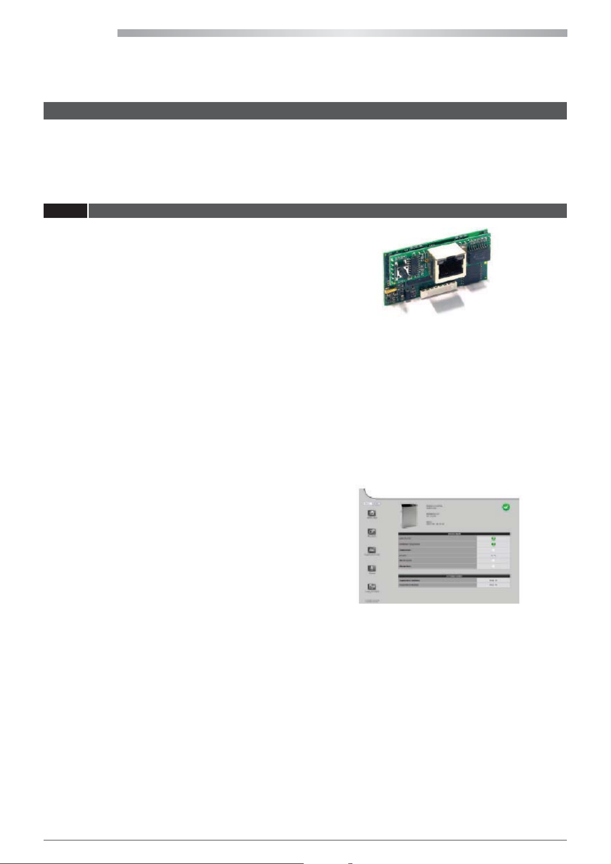
Ethernet GWeb with GWeb supervision software is
integrated in the HiWarm unit.
The WEB board allows the controller on board the unit to
connect with the RJ45 Ethernet network at 10 Mbps. The
operating system used is Linux 2.4.21.
It is installed directly on the serial port of the advanced
controller and a static or dynamic (DHCP) IP address is used.
GWeb supervision software allows for the following:
- viewing the unit status;
- viewing the active alarms and alarm history;
- recording data with 10 variables that can be set;
- downloading all the data records from a web browser or via FTP;
- editing the main parameters;
- in case of an alarm, sending an e-mail to 5 dierent recipients.
GWeb also allows for monitoring to be performed via the following protocols:
- with SNMP v1 & v2c protocol;
- with BACnet Ethernet or BACnet/IP protocol.
The parameters relative to SNMP and BACnet protocol management are set from the Administrator conguration pages, as
shown in the gure:
The current on board control functions are:
- control of the various operating parameters by means of
a keypad set-up on the electric panel;
- compressor activation/deactivation to maintain the
chiller inlet temperature set-point;
- management of various alarms:
t IJHIMPXQSFTTVSF
t BOUJGSFF[F
t øPXTXJUDI
t QVNQBMBSN
- pump management;
- displaying the operating parameters;
- heat exchanger anti-freeze protection;
- controlling the maximum number of compressor start-ups;
- serial output management (optional);
- interfacing via WEB with the Webgate option through a simple connection and any internet browser;
- summer/winter changeover and on/o control via potential-free contact or on board the unit;
- set points can be set on board the unit or via external analogue contacts only for 0-5V utility;
- electrical load management and automatic modulation of the unit to prevent exceeding any power limits.
40
All copying, even partial, of this manual is strictly forbidden RG66007967 - Rev 02
Page 41
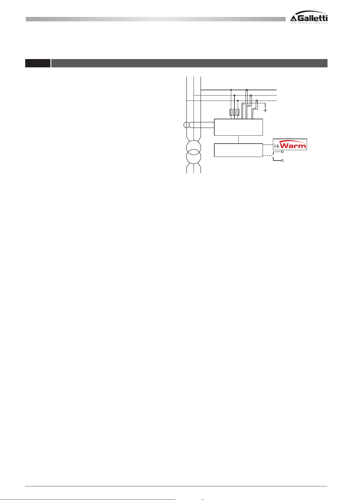
6.2 ELECTRICAL LOAD MANAGEMENT FUNCTION
This function allows the electrical loads to be managed and
priorities to be assigned to our HiWarm system or other
utilities, such as appliances.
This function requires a current transformer (CT) set
upstream the mains meter. This CT must be of good quality
(class I) and the selected ratio must guarantee a constant
amperometric signal to the secondary within the 0.5 ÷ 5A
range.
Its power must be equal to or greater than 5VA to guarantee
regulation precision.
If it is installed away from the regulator, the dissipated power
from the connection wires (approx. 0.2 VA per metre on
two-wire lines with a 2.5 mm
normal amperometric consumption (approx. 2 VA) and that
of any instruments connected in the amperometric circuit.
2
section) must be added to the
LOAD
TA
RRSST
MAINS
T
Microprocessor
utility programmable
management control
Other utilities
(e.g. appliances)
The wires used for the CT secondary connection must have a minimum section of 2.5 mm
2
.
The CT connection must not be protected by a fuse or interrupted by an isolator switch.
The user must insert the current transformer (CT) on the system line that is to be corrected, upstream the network loads and
the branch point of the power supply for the power factor correction panel: the installed CT must measure all the absorbed
currents of the system, inductive (motors or similar) as well as capacitive (condensers). Any condensers for the xed power
factor correction must be installed downstream the CT, unless they are used for the power factor correction of the system
power supply transformer.
Professionally qualied personnel may carry out the installation according to the instructions. The installer must connect
the wires to the transformer in the correct direction for the CT to function correctly (as indicated in the structure of the CT).
Otherwise, they will be connected incorrectly and result in poor performance or possibly null.
An incorrect installation can harm persons or damage objects for which the manufacturer cannot be held liable.
The CT is then connected to the microprocessor of the HiWarm, which controls the utility energy absorption, according to
the power available that reaches it from the CT, with a possible derating of the HiWarm or turning o the other utilities, if
required.
By doing so, the management and distribution of the absorbed current over time can be understood and the saved data are
archived and can be downloaded via a serial port.
All copying, even partial, of this manual is strictly forbiddenRG66007967 - Rev 02
41
Page 42
HIWARM
6.3 USER INTERFACE
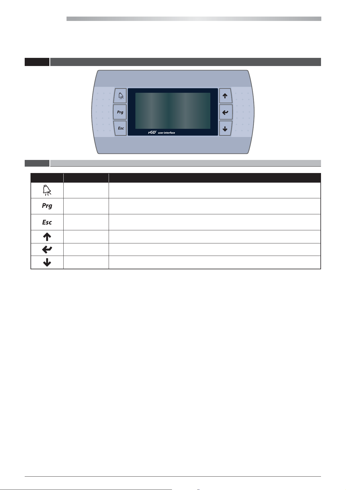
6.3.1 DESCRIPTION OF THE KEYPAD
Key Description
ALARM Press the ALARM key to reset the alarms. The button lights up when an alarm is triggered.
PROGRAM
ESC
UP Press the UP key to go to the next screen or increase the value of a parameter.
ENTER Press the ENTER key to go to the parameter eld to be edited and to conrm any change.
DOWN Press the DOWN key to go to the previous screen or decrease the value of a parameter.
Press the PRG key to enter the main menu.
Press the ESC key to move up one level in the menu.
42
All copying, even partial, of this manual is strictly forbidden RG66007967 - Rev 02
Page 43
6.3.2 MAIN SCREEN
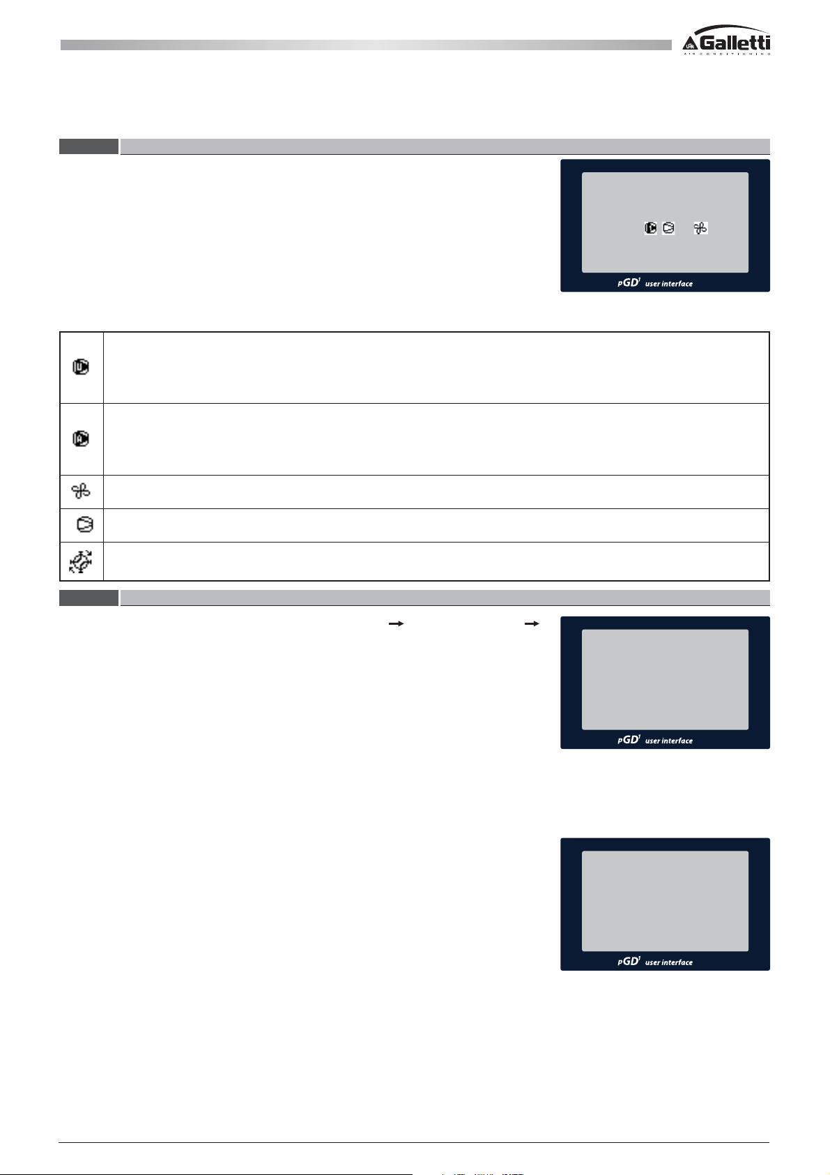
When the unit is started up the control logic will display the mode on the initial
screen:
U1 08:00 28/09/2011
UT 14.0˚C
DHW
ON
32.5˚C
On which the following information is also displayed besides the utility temperature (summer or winter mode) and the
domestic hot water temperature:
Indicates that the utility pump is active. When the utility tank is present and the utility probe is enabled, it also
indicates that the winter or summer mode request is active.
If the utility tank is not present, the utility pump is always active unless the utility activation request is provided
from a digital input.
Indicates that the DHW pump is active. When the DHW tank is present and the DHW probe is enabled, it also
indicates that the DHW production request is active.
If the DHW tank is not present, the utility pump is always active unless the DHW activation request is provided
from a digital input.
Indicates that the fans are running.
Indicates that the compressor request is active to satisfy the (utility) air conditioning or DHW request.
Indicates that the 4-way water valve of the utility is in the positioning phase. Positioning always occurs when the
unit is powered and each time the utility operating mode changes (winter or summer).
6.3.3 SELECTING THE CONTROL MODE
Unit start-up and shutdown can be set in the User menu
Lan and Supervision J1
as follows:
- press the PRG key to enter the main menu;
- use the UP and DOWN keys to scroll the menu to select USER;
- press ENTER and enter the password (default: 100) using the UP and DOWN keys;
- press ENTER to con rm the password and access the user menu;
- use the UP and DOWN keys to select “Lan and Supervision”;
- press the ENTER key to access the following screen (J1):
Enable one or more unit start-up options on this screen. The options are:
- from the display keys (local or remote, separately);
- via external contacts (voltage free);
- via an external supervision system;
- via time bands.
Since they are operating functions, if more than one is selected, they must all consent
the unit to be operational. The status of the unit is displayed on the initial screen and if
the unit is OFF, the condition that forces this mode is also speci ed. The display may be:
- ON: the unit is ON (all the unit On/O logics give consent to operation).
- Alarms OFF: the unit is OFF due to an alarm being triggered. Regardless of the status
of the enabled consents, certain alarms force the unit to shutdown.
- Superv. OFF: the unit is switched o via Supervision.
- Bands OFF: the unit is switched o according to the scheduled time bands.
- Remote OFF: the unit is switched o via a remote digital contact.
- Keypad OFF: the unit is switched o via the keypad. If this option is disabled, the
unit status cannot be modi ed via the keypad. N.B.: If the unit is switched o via the
keypad and this mode is then disabled, the unit cannot be switched on.
UNIT ON/OFF J1
ENABLE ON/OFF FROM:
- KEYPAD : NO
- REMOTE CONTACT : NO
- SUPERVISION : NO
- BANDS : NO
U1 08:00 28/09/2011
UT 14.0˚C
DHW
KEYPAD OFF
32.5˚C
All copying, even partial, of this manual is strictly forbiddenRG66007967 - Rev 02
43
Page 44

HIWARM
Press the DOWN key with the cursor in the top left side on the J1 screen to access the
following screen (J2):
The type of activation for the unit operating modes can be selected here as follows:
- via the display keys;
- via external contacts connected to the unit terminal board;
- remote control via a supervision system.
Moreover, the DHW or utility (summer/winter) mode can be disabled/enabled.
ON-OFF CONTROL VIA THE KEYPAD
Start-up the unit by keeping the ENTER key pressed until the following screen appears:
Select the utility operating mode, heating or cooling, via the UP or DOWN keys, and
then press the PRG key to conrm.
Press ESC to exit without starting-up the unit.
N.B. unit start-up also activates the production of domestic hot water (DHW).
Actual compressor and pump start-up depends on the actual utility and/or DHW
request determined by the set-point and set temperatures.
UNIT CONTROL J2
-› FROM LOCAL KEYPAD PGD1
UTILITY ACTIVATION : NO
DHW ACTIVATION : NO
START-UP UNIT
-› COOLING
PRG : CONFIRM
ESC : CANCEL
Stop the unit by keeping the ENTER key pressed until the following screen appears:
Press the PRG key to conrm unit shutdown and press ESC to exit without any action,
SHUTDOWN UNIT?
thereby leaving the unit on.
PRG : CONFIRM
ESC : CANCEL
ON-OFF CONTROL VIA EXTERNAL CONTACTS
Qualied personnel must implement the electrical connection between the external contacts and the terminals in the unit
electric panel before using this mode.
With reference to the unit wiring diagram, the following terminals are available with their relative functions:
X3:11-14 > Unit ON-OFF.
X3:24-81 > utility activation (summer/winter air conditioning according to the selected mode).
X3:24-82 > DHW production activation.
X3:51-52 > selection of the utility mode.
Actual compressor and pump start-up depends on the set-points and set temperatures.
ON-OFF CONTROL VIA SUPERVISION
Supervision control assumes a specic communication board is installed (pCOWeb or
RS485) that acts as an interface between the main unit control and the supervision
SUPERVISION SYSTEM J6
system.
The type of protocol and main communication conguration parameters can be set in
the User menu
Lan and Supervision J6.
COMMUNICATION SPEED
IDENTIFICATION NUMBER : 000
PROTOCOL : CAREL
:1200BPS
Besides all the previous controls (on-o, utility and DHW activation), the supervision
system also allows the status of all the alarms to be read, the alarms to be reset, the
operating set-points to be modied and all the operating parameters to be read.
Refer to the software manual for the complete list of the supervision variables and for
more information.
44
All copying, even partial, of this manual is strictly forbidden RG66007967 - Rev 02
Page 45

ON-OFF CONTROL VIA BANDS
If the clock card option is present, the unit activation On/O bands can be set.
Activation
- Clock board installed.
- On-O activation via bands (User menu
Lan and Supervision J1).
On/O Bands Conguration
Four dierent time bands are present (User menu
Clock L2), two of which can be
congured, which are to be used to set the logic of the dierent days of the week.
Band 1 (F1): denes 2 unit start-up intervals within 24 hours.
UNIT ON/OFF J1
ENABLE ON/OFF FROM:
- BANDS :YES
ON/OFF BANDS L2
BAND 1
ON 00:00 - OFF 00:00
ON 00:00 - OFF 00:00
Band 2 (F2): denes 1 unit start-up interval within 24 hours.
Band 3 (F3): the unit is always on.
Band 4 (F4): the unit is always o.
Weekly program conguration
Once the On/O bands are set, they must be used to dene the logic of the dierent
days of the week (User menu
Clock L3).
N.B.: the On/O control via bands is simply consent to operate, which involves unit
start-up solely if all the activated On/O options (via User menu
Lan and Supervision)
give consent.
N.B.: the operation set within the day must then be set in the Set-point menu solely for
the utility, whereas the DHW set-point is xed (see the “set-points” paragraph).
ON/OFF BANDS L2
BAND 2
ON 00:00 - OFF 00:00
BAND SELECTION L3
MON: F1 TUES: F1
WED: F1 THURS: F1
FRI: F1 SAT: F1
SUN: F1
All copying, even partial, of this manual is strictly forbiddenRG66007967 - Rev 02
45
Page 46
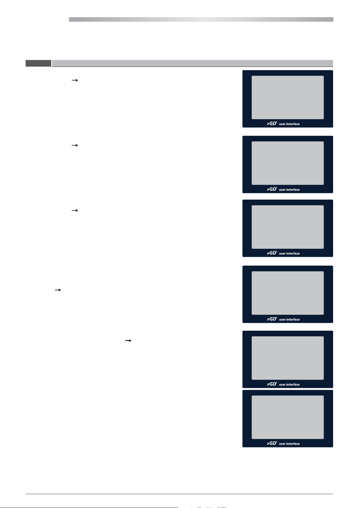
HIWARM
6.3.4 SELECTING THE SET-POINT
Active Utility Set-point
(Set-point menu
The rst screen displayed in the SET-POINT menu indicates the set-point value used in
the utility regulation logic. This value is the result of the overall set-point management
as a result of automatic variations, corrections and restrictions.
Active DHW Set-point
(Set-point menu
Indicates the set-point value used in the DHW regulation logic. This indicates the
minimum DHW storage temperature below which the control logic is activated.
F0)
F1)
UTILITY SET-POINT F0
ACTIVE: 12.0˚C
- SECONDARY : -
- FROM BAND: : -
- REMOTE CORRECTION : -
- COMPENSATION : -
- LIMITED : -
DHW SET-POINT F1
ACTIVE: 40.0˚C
Main Set-point
(Set-point menu
F2)
The main operating set-point in the various modes can be set on this screen.
Time band set-point solely for the utility
A time band for each day of the week can be set from the SET-POINT menu, to control
the variation of the set-point during the intervals of the day when the unit is ON (Set-
point menu
F7).
The summer and winter set-points to be used during the time bands and not must be
set together with these (Set-point menu
F5-F6).
SETTING F2
MAIN SET-POINT
- COOLING : 12.0˚C
- HEATING : 30.0˚C
- DHW : 40.0˚C
BAND SET-POINT F7
MON : 00:00 - 00:00
TUES : 00:00 - 00:00
WED : 00:00 - 00:00
THURS : 00:00 - 00:00
FRI : 00:00 - 00:00
SAT : 00:00 - 00:00
SUN : 00:00 - 00:00
SETTING F5
TIME BAND SET-POINTS
(COOLING)
INDOOR BAND : 00.0˚C
OUTDOOR BAND : 00.0˚C
SETTING F6
TIME BAND SET-POINTS
(HEATING)
INDOOR BAND : 00.0˚C
OUTDOOR BAND : 00.0˚C
46
All copying, even partial, of this manual is strictly forbidden RG66007967 - Rev 02
Page 47
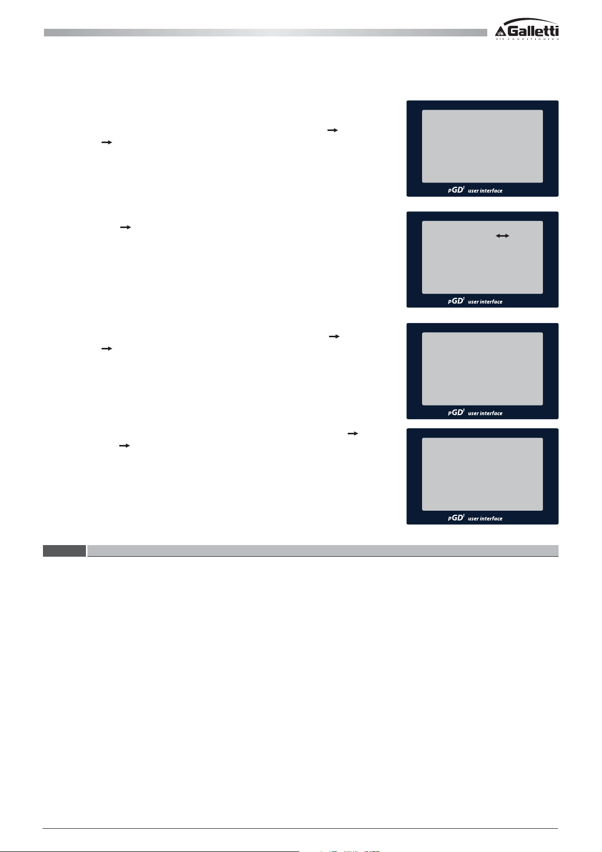
Required conditions for time band management:
- clock board present;
- selected "via bands" set-point automatic variation (User menu
parameters
H4).
Set-points and
Secondary set-point from a digital input
(Set-point menu
F3)
The summer and winter secondary set-point values, controlled from the digital input
ID14, accessible from terminals X3:61-62, can be set from the SET-POINT menu. The
regulation will use the main set-point when the digital input is open and the secondary
set-point when it is closed.
Condition:
- digital input congured as “ -> secondary set-point” (User menu
parameters
H1);
Set-points and
SET-POINT H4
AUTOMATIC VARIATION
-› VIA TIME BANDS
SETTING THE F3
SECONDARY SET-POINT
COOLING
HEATING
DIN14 CONFIGURATION H1
-› SECONDARY SET-POINT
00.0˚C
:
00.0˚C
:
- selected "via digital input" set-point automatic variation (User menu
and parameters
H4).
Set-points
SET-POINT H4
AUTOMATIC VARIATION
-› VIA A DIGITAL INPUT
6.3.5 ALARMS
In the event of an anomaly or the unit is blocked due to a safety device being triggered, the red LED beneath the ALARM key
lights up.
Press the ALARM key once to access the list of active alarms, then use the UP and DOWN keys to scroll the list. Each alarm is
identied by a code and a brief description; the complete list is found in the software manual.
Press the ALARM key again to reset the alarms, provided the cause that triggered them has been resolved.
If the specic function is enabled, all the alarms besides the high and low pressure alarms are automatically reset after a preset time interval.
Information that at least one alarm is active can be communicated externally via a potential-free contact in wired exchange
on terminals X3:31-32-33 (see Wiring diagram), or if a supervision systems is available, the status of each alarm can be read
together with that of the main alarm, the alarms can be reset and a datalogger can be set up (pCOWeb).
The information regarding triggered alarms on terminals 31-32-33 can be used to:
- remote control the alert (e.g. via a warning light);
- activate an auxiliary backup device for DHW production (e.g. an electric resistance in the tank controlled by a mechanical
thermostat).
All copying, even partial, of this manual is strictly forbiddenRG66007967 - Rev 02
47
Page 48
HIWARM
All the HiWarm alarms and their meaning are found in the list below:
ALARM
CODE
001 DIGITAL INPUT ALARM
002 UTILITY PUMP CIRCUIT BREAKER ALARM
004 UTILITY FLOW ALARM
005 PROBE FAULT ON ANALOGUE INPUT B1 ALARM
006 PROBE FAULT ON ANALOGUE INPUT B2 ALARM
007 PROBE FAULT ON ANALOGUE INPUT B3 ALARM
008 PROBE FAULT ON ANALOGUE INPUT B4 ALARM
009 PROBE FAULT ON ANALOGUE INPUT B5 ALARM
010 PROBE FAULT ON ANALOGUE INPUT B6 ALARM
011 PROBE FAULT ON ANALOGUE INPUT B7 ALARM
012 PROBE FAULT ON ANALOGUE INPUT B8 ALARM
013 LOW PRESSURE ALARM
015 PRESSURE SWITCH OR COMPRESSOR CIRCUIT BREAKER HIGH PRESSURE ALARM
017 LOW PRESSURE PROBE ALARM
019 HIGH PRESSURE PROBE ALARM
023 FAN CIRCUIT BREAKER ALARM
025 PUMP 1 EXCEEDED OPERATING HOURS
026
027 PHASE DIRECTION OR MISSING PHASE ALARM
028 ANTI-FREEZE ALARM
030 COMPRESSOR EXCEEDED OPERATING HOURS THRESHOLD
038 CLOCK BOARD FAULT
040 DOMESTIC HOT WATER PUMP CIRCUIT BREAKER ALARM
069 PCOE BOARD OFFLINE
072 DHW FLOW ALARM
073
074 COMPRESSOR HEAD HIGH TEMPERATURE ALARM
075 OFFLINE SUPERNODE ALARM
076 OFFLINE EVD-EVO VALVE DRIVER ALARM
PUMP 2 EXCEEDED OPERATING HOURS
ENVELOPE ALARM
> compressor start-up failure
> high temperature compressor discharge
> high condensation pressure
> low evaporation pressure
> high evaporation pressure
> low pressure dierence
> low pressure ratio
DESCRIPTION
48
All copying, even partial, of this manual is strictly forbidden RG66007967 - Rev 02
Page 49
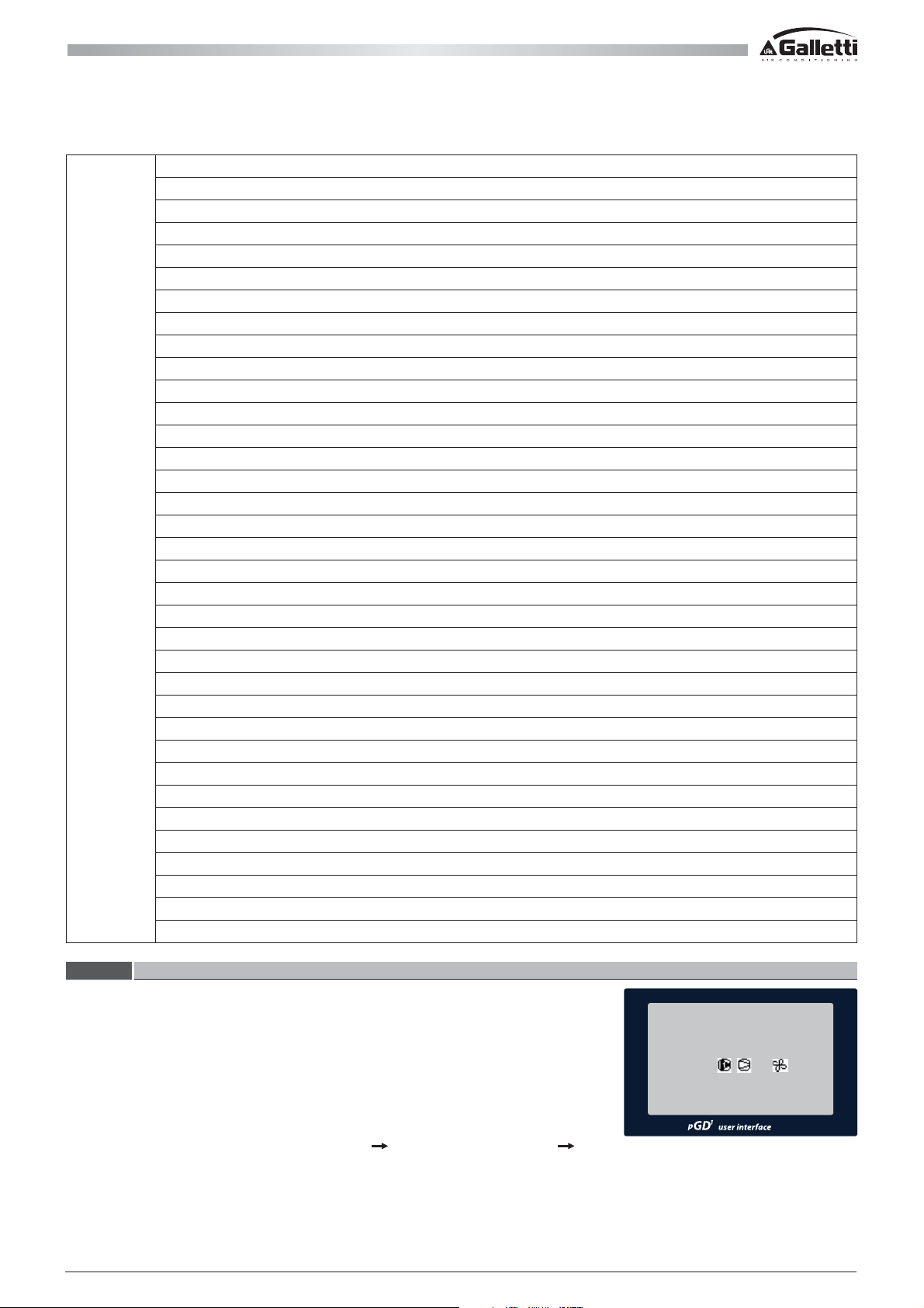
077
SUPERNODE SLAVE BOARD ALARM
With Frecon-APY inverter:
- heat-sink over temperature
- overcurrent during acceleration
- overcurrent
- overcurrent during deceleration
- DC Bus undervoltage
- DC Bus overvoltage
- faulty PFC converter
- overload
- serial communication timeout
- heat-sink temperature probe error
- general alarm
WITH CAREL POWER+ INVERTER:
- Overcurrent
- Motor Overcurrent
- Overvoltage
- Undervoltage
- Over temperature
- Undertemperature
- Overcurrent HW
- Motor Over temperature
- Drive fault
- Cpu error
- Default parameters
- DC bus ripple
- Serial communication timeout
- Thermistor error
- Autotuning error
- Disabled drive
- Missing motor phase
- Faulty fan
- Stalled motor
- Drive fault
EVD-EVO VALVE DRIVER ALARM
6.3.6 OPERATION MODE
The possible methods of selecting unit operating modes is found below, in priority
order:
1 Via a Digital Input.
2 Via Keypad or Supervision.
When the unit is started-up, the control logic will display the information regarding the
mode on the initial screen (correspondence between the symbol used on the display
and the mode can be con gured via User menu
All copying, even partial, of this manual is strictly forbiddenRG66007967 - Rev 02
Set-points and Parameters Hh).
U1 08:00 28/09/2011
UT 14.0˚C
DHW
ON
12.5˚C
49
Page 50
HIWARM
7 - MAINTENANCE AND AFTER SALES SERVICE
7.1 TROUBLESHOOTING
The most common causes that can block the heat pump or cause a malfunction are listed in the following pages. They are
listed according to the easily identiable symptoms.
WARNING
FAULT ANALYSIS OF POSSIBLE CAUSES CORRECTIVE ACTION
The unit does not start-up. No power supply. Check its presence both on the primary
Faulty high pressure. Insucient air ow rate to the
Be very careful when carrying out the various recommended problem-solving operations:
over-condence can cause serious injuries for unskilled persons. It is therefore recommended
to contact the manufacturer or a qualied technician after having identied the cause.
and auxiliar
The circuit board is not powered. Check the fuses.
Alarms have been triggered. Check the microprocessor panel for
triggered alarms, eliminate their cause
and restart the unit.
Check that all fans turn correctly.
condenser.
Air in the circuit, detected by air
bubbles on the ow indicator and subcooling values reaching over 5°C.
Unit too loaded, detected by subcooling values reaching over 8°C.
Clogged thermostatic valve and /
or lter. Such faults may occur in the
presence of low pressure.
Insucient water ow rate in heat
pump mode.
Check the condenser air inlet T and
prevent any recirculation.
Check that the maximum RMS voltage
reaches the fans. If necessary, check the
pressure transducers that control the
revolution controller [optional].
Make sure the nned coils are clean.
Drain and pressurise the circuit and
then verify whether there are any leaks.
Drain the circuit slowly [more than 3
hours] up to 15 Pa and then recharge in
the liquid phase.
Drain the circuit.
Check the temperature upstream and
downstream the valve and lter and
have them replaced, if necessary.
Check the pressure drops of the water
circuit and/or the correct operation of
the pump [rotation direction]. Check
the outlet water T and make sure it is
45°C or less.
y circuit.
50
All copying, even partial, of this manual is strictly forbidden RG66007967 - Rev 02
Page 51
FAULT ANALYSIS OF POSSIBLE CAUSES CORRECTIVE ACTION
Low condensation pressure. Fault in the transducers. Check the transducers and verify that
the depr
essor on the Schrader valves
that they are connected to works
correctly.
Outdoor T too low and/or presence of
strong wind.
Mount the condensation control and/
or protect the unit from dominant
winds.
Low water T if in heat pump mode. Make sure the thermal load is adequate
for the power of the unit.
Low evaporation pressure. Low water ow rate. Check the correct rotation of the
pumps. Check for pressure drops in
the water circuit. Check the tightness
of the one-way valve of the pump unit
(optional).
Malfunctioning thermostatic valve. Check its opening, and adjust if
necessary, by heating the bulb by
hand. If there is no response, replace it.
Clogged lter. Pressure drops through the lter
must not exceed 2°C (saturation
temperature). Should it happen,
replace the lters.
Low condensation T. Make sure the condensation control
works properly [if present].
Low refrigerant charge. Check the charge by measuring the
sub-cooling; if it is below 2°C, charge
with refrigerant.
Frosted coil if in heat pump mode. Check the correct defrost parameter
settings. Make sure the 4-way valve
works properly.
Low outdoor T if in heat pump mode. Make sure the operating limits are
respected and eliminate possible bypasses and air recirculation.
The compressor does not start. Internal thermal protector tripped. Check the status of the thermal contact
in models equipped with protection
modules. Identify the causes after
restarting.
Tripped circuit breakers or line fuses
after a short circuit.
Check the cause by measuring the
resistance of the individual coils and
the isolation towards the chassis before
re-connecting the power.
One of the HP or LP switches has
tripped.
The phases in the distribution cabinet
Check the microprocessor and
eliminate the causes.
Check the phase sequence relay.
have been inverted.
All copying, even partial, of this manual is strictly forbiddenRG66007967 - Rev 02
51
Page 52
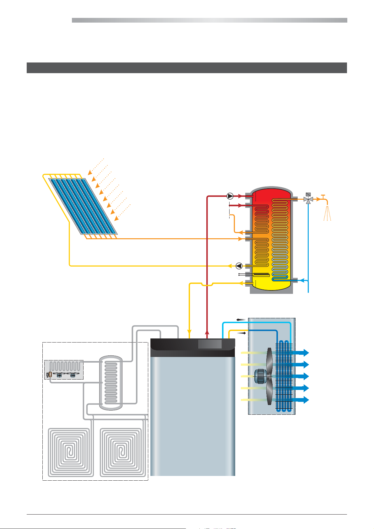
HIWARM
8 - OPTIONAL STORAGE TANKS
HiWarm can heat technical water for domestic hot water production. Domestic hot water production always requires a water
storage tank (preferably technical) on the circuit used for this function. The storage tank is used to meet demand peaks
without installing thermal powers that are too high. This leads to regular and continuous system operation and therefore
better thermal performance. The water heated by the unit is stored inside the tank and the energy stored this way allows the
tank to be used with an instantaneous preparer. The manufacturer proposes this solution as it prevents unnecessary antilegionella cycles and allows for good thermal eciency by heating the water with a thermal approach in countercurrent
mode. An electric resistance can also be combined.
thermal
solar panel
High T
Resistances
Domestic
hot water
storage tank
DHW
Aqueduct
52
All copying, even partial, of this manual is strictly forbidden RG66007967 - Rev 02
Page 53
9 - TECHNICAL DATA
012
Compressor status [Hz] 30 110 30 120 30 120
ESEER Eurovent radiant panels (utility @ 23-18°C) 8.61 6.69 6.52
urovent fan-coils (utility @ 12-7°C) 5.65 5.30 5.24
ESEER E
Cooling Capacity [kW] 3.0 11.2 6.0 20.4 9.6 31.9
Compressor Absorbed Power [kW ] 0.6 3.1 1.3 7.0 2.1 11.0
Compressor Absorbed Current [A] 7.4 8.3 11.1 12.6 16.6 19.8
Fan Absorbed Power [kW] 0.08 0.30 0.07 0.45 0.06 0.60
Fan Absorbed Current [A] 0.40 1.40 0.10 0.80 0.10 1.10
EER [-] 4.41 3.26 4.38 2.71 4.50 2.72
UTILITY Water Flow Rate [kg/h] 519 1921 1026 3517 1646 5480
Cooling @ 35°C air 12/7°C water
UTILITY Water Pressure Drops [kPa] 2.0 19.0 3.0 26.0 3.0 23.0
3
DISSIPATION Water Flow Rate [m
Cooling Capacity [kW] 4.2 15.7 8.5 28.1 8.6 44.0
Compressor Absorbed Power [kW ] 0.6 3.2 1.3 7.5 1.2 11.8
Compressor Absorbed Current [A] 6.9 8.6 10.9 13.2 3.2 20.4
Fan Absorbed Power [kW] 0.08 0.30 0.06 0.45 0.05 0.60
Fan Absorbed Current [A] 0.40 1.40 0.10 0.80 0.10 1.10
EER [-] 6.27 4.41 6.34 3.46 6.80 3.47
UTILITY Water Flow Rate [kg/h] 714 2696 1458 4834 1472 7565
Cooling @ 35°C air 23/18°C water
UTILITY Water Pressure Drops [kPa] 3.0 37.0 4.0 49.0 11.1 44.0
DISSIPATION Water Flow Rate [m
Heating Capacity [kW] 3.3 16.6 7.6 32.3 11.8 51.7
Compressor Absorbed Power [kW ] 0.9 4.3 2.1 9.5 3.2 14.2
Compressor Absorbed Current [A] 12.8 18.4 15.2 23.7 20.2 25.9
Fan Absorbed Power [kW] 0.08 0.30 0.06 0.45 0.05 0.60
Fan Absorbed Current [A] 0.40 1.40 0.10 0.80 0.10 1.10
COP [-] 3.46 3.54 3.58 3.14 3.63 3.37
DHW Flow Rate [kg/h] 714 2860 1307 5563 2169 8885
DHW Pressure Drops [kPa] 3.0 41.0 4.0 64.0 4.0 61.0
DHW @ 50/55°C and 30°C outdoor air
DISSIPATION Water Flow Rate [m
Cooling Capacity [kW] 2.4 9.2 4.7 17.1 7.9 28.1
Heating Capacity [kW] 3.2 13.1 6.4 25.5 10.6 40.9
Compressor Absorbed Power [kW ] 0.9 4.1 1.8 8.9 2.9 13.4
Compressor Absorbed Current [A] 10.6 11.0 14.8 15.3 22.7 23.7
Fan Absorbed Power [kW] 0.0 0.0 0.0 0.0 0.0 0.0
Fan Absorbed Current [A] 0.0 0.0 0.0 0.0 0.0 0.0
COP [-] 3.55 3.16 3.49 2.86 3.68 3.03
UTILITY Water Flow Rate [kg/h] 407 1580 806 2944 1357 4839
UTILITY Water Pressure Drops [kPa] 1.0 13.0 3.0 18.0 3.0 18.0
Cooling + DHW @ 50/55°C and 12/7°C
DHW Flow Rate [kg/h] 556 2252 1107 4393 1829 7026
DHW Pressure Drops [kPa] 2.0 26.0 4.0 40.0 4.0 38.0
/h] 3500 7000 5250 10500 7000 14000
3
/h] 3500 7000 5250 10500 7000 14000
3
/h] 3500 7000 5250 10500 7000 14000
022
033
All copying, even partial, of this manual is strictly forbiddenRG66007967 - Rev 02
53
Page 54
HIWARM
012
Compressor status [Hz] 30 110 30 120 30 120
ESEER Eurovent radiant panels (utility @ 23-18°C) 8.61 6.69 6.52
urovent fan-coils (utility @ 12-7°C) 5.65 5.30 5.24
ESEER E
Heating Capacity [kW] 2.9 11.7 5.8 22.7 9.4 34.9
Compressor Absorbed Power [kW ] 0.7 3.3 1.5 7.1 2.3 10.8
Compressor Absorbed Current [A] 8.6 8.9 12.3 12.7 18.9 19.6
Fan Absorbed Power [kW] 0.30 0.30 0.45 0.45 0.60 0.60
Fan Absorbed Current [A] 1.40 1.40 0.80 0.80 1.10 1.10
COP [-] 2.84 3.23 3.00 2.95 3.21 3.02
UTILITY Water Flow Rate [kg/h] 499 2014 1000 3903 1618 5998
UTILITY Water Pressure Drops [kPa] 2.0 21.0 4.0 32.0 4.0 28.0
LT Heating @ 40/45°C and 7°C outdoor air
LT Heating @ 30/35°C and 7°C outdoor air
Power
absorption
Noise
emission
Compressor
Dimensional
weights and
connections
DISSIPATION Water Flow Rate [m
Heating Capacity [kW] 3.1 12.2 6.1 23.5 9.8 35.7
Compressor Absorbed Power [kW ] 0.6 2.7 1.2 5.8 1.9 8.9
Compressor Absorbed Current [A] 7.2 7.5 10.6 11.0 15.8 16.5
Fan Absorbed Power [kW] 0.30 0.30 0.45 0.45 0.60 0.60
Fan Absorbed Current [A] 1.40 1.40 0.80 0.80 1.10 1.10
COP [-] 3.48 4.03 3.69 3.65 3.91 3.71
UTILITY Water Flow Rate [kg/h] 527 2093 1050 4034 1687 6147
UTILITY Water Pressure Drops [kPa] 2.0 22.0 4.0 34.0 4.0 29.0
DISSIPATION Water Flow Rate [m
Power supply single-phase 230/1/50 three-phase 400/3/50 three-phase 400/3/50
FLA with fans with phase cut [A] 21,8 23,0 33,2
FLA with EC electronic fans [A] 21,2 22,0 31,8
Lw indoor unit noise power level [dBA] 54 55 57
Lp indoor unit noise pressure (10m Q=2) [dBA] 26 27 29
Lw outdoor unit noise power level [dBA] 65 66 69
Lp outdoor unit noise pressure (10m Q=2) [dBA] 37 38 41
Type of compressor Twin Rotary Scroll Scroll
Electric motor technology BLDC BLDC BLDC
Oil charge for compressor [l] 1.8 1.5 1.8
N. of cooling circuits 1 1 1
Indoor module dimensions (LxHxD) [mm] 803x1120x501.5 803x1247x606 803x1247x606
Outdoor module dimensions (LxHxD) [mm] 1120x1230x450 1410x1280x450 2000x1512x550
Indoor module weight [kg] 190 260 270
Outdoor module weight [kg] 50 100 123
Size of hydraulic connections [mm] 28 35 35
Chiller connections Rotalock Rotalock Rotalock
3
/h] 7000 7000 10500 10500 14000 14000
3
/h] 7000 7000 10500 10500 14000 14000
022
033
54
All copying, even partial, of this manual is strictly forbidden RG66007967 - Rev 02
Page 55
10 - DECOMMISSIONING THE UNIT
When the unit has reached the end of its working life and must be removed and replaced, a number of measures must be
followed:
- the refrigerant gas it contains must be collected by qualied personnel and sent to a waste collection facility;
- the compressor lubricating oil must also be collected and sent to a waste collection facility;
- if the framework and components cannot be reused, they must be separated and scrapped according to the type of
material: this applies especially for the considerable quantities of copper and aluminium present in the unit.
This will facilitate the work carried out in the waste collection, disposal and recycling facilities and minimise the environmental
impact of such processes.
ATTENTION
Please note it is mandatory to register the loading and unloading of special and toxic-harmful waste.
Special and toxic-harmful waste must be collected by authorised companies.
Special and toxic-harmful waste must be disposed of in compliance with the applicable laws in the user's country.
Dismantle the unit according to the requirements imposed by law in force in the user's country. Before demolishing the unit,
ask the relative Authority to perform an inspection and issue a report.
Lastly, scrap the unit in compliance with the applicable laws in the user's country.
WARNING
- If the unit or part of it has been put out of service, any parts that are likely to pose a risk
must be protected.
- Remember that whenever a part is replaced and the used part must be disposed of
separately, always refer to the relative laws in force.
Qualied personnel must dismantle and demolish the unit.
10.1 ENVIRONMENTAL PROTECTION
The law [EC 2037/00] that regulates the use of stratospheric ozone depleting substances and greenhouse gases bans disposal
of refrigerant gases in the environment and requires whoever is in their possession to collect them and, at the end of their
useful life, return them to the dealer or take them to a suitable waste collection facility.
The HFC R410A refrigerant is not harmful to the ozone layer but is included among the greenhouse eect substances and
must therefore be handled in compliance with the above-mentioned requirements.
ATTENTION
Therefore, special care should be taken when carrying out maintenance work to minimise
refrigerant leaks.
11 - WATER PRESSURE DROPS
11.1 PRESSURE DROPS IN EVAPORATOR
N.B.: refer to the technical document of the product (PD) for the relative information.
11.2 HEAT RECOVERY UNIT PRESSURE DROPS
N.B.: refer to the technical document of the product (PD) for the relative information.
All copying, even partial, of this manual is strictly forbiddenRG66007967 - Rev 02
55
Page 56
HIWARM
12 - R410A REFRIGERANT SAFETY DATA SHEET
CHEMICAL NATURE OF THE PRODUCT MIXTURE OF:
EINECS Compliant.
MAJOR RISKS -
YSICAL AND CHEMICAL RISKS Thermal decomposition in toxic and corrosive products.
PH
SPECIFIC / EC RISKS Preparation is not classied as dangerous.
GENERAL INFORMATION -
TION Move the person in question to fresh air.
INHALA
CONTACT WITH SKIN Rinse with plenty of water.
CONTACT WITH THE EYES Rinse immediately, with plenty of water and for a long time.
SWALLOWED Hospitalization.
PROTECTION OF RESCUERS Wear suitable respiratory equipment when intervening in a saturated atmosphere.
INSTRUCTIONS FOR THE DOCTOR Do not administer catecholamines (due to the cardiac sensitization caused by the
SPECIFIC HAZARDS Thermal decomposition in toxic and corrosive products.
SPECIFIC METHODS OF INTERVENTION Cool the containers / tanks with jets of water.
SPECIAL PROTECTION SYSTEMS FOR THE FIRST AIDERS Wear breathing apparatus and protective clothing.
PERSONAL PRECAUTIONS Avoid contact with your skin, eyes and inhalation of vapours.
ENVIRONMENTAL PROTECTION PRECAUTIONS Minimise waste in the environment.
Technical Measures/Precautions Applicable product storage and handling provisions:
Recommendations for use Prohibit sources of ignition and contact with hot surfaces.
Technical measures/Storage methods Store in the original container at room temperature.
Recommendations Ordinary steel.
To be avoided Alloy containing more than 2% magnesium.
PRECAUTIONS TO BE TAKEN Make sure there is enough air recirculation and/or intake in the workplace.
ONTROL PARAMETERS -
C
Exposure limit values FORANE 32:
PERSONAL PROTECTIVE EQUIPMENT Respirat
ory protection Wear suitable respiratory equipment in case of insucient ventilation.
Hand protection Gloves.
Eye protection Safety goggles.
COMPOSITION/INFORMATION REGARDING THE INGREDIENTS
FORANE 32 (DIFL
CAS: 75-10-5 EINECS: 200-839-4 F+ R_12.
FORANE 125 (PENTAFLUOROETHANE):
CAS: 354-33-6 EINECS: 206-557-8.
IDENTIFICATION OF RISKS
FIRST AID
If necessary, provide oxygen or articial respiration.
Frostbite must be treated as thermal burns.
If the irritation persists, consult an ophthalmologist.
product).
FIRE PREVENTION
ydrouoric acid.
H
Carbon oxides.
One of the ingredients of this preparation forms explosive mixtures with air.
(FORANE 32).
Prohibit all sources of sparks and ignition - Do not smoke.
MEASURES IN CASE OF ACCIDENTAL DISPERSION
se personal protective equipment.
U
In an enclosed area: ventilate the area or use breathing apparatus (risk of anoxia).
No smoking.
HANDLING AND STORAGE
PRESSURISED LIQUEFIED GAS.
P
rovide ventilation and an appropriate exhaust system in line with the equipment.
DO NOT SMOKE.
Keep away from open ames, hot surfaces and sources of ignition.
Store in a cool and well ventilated area.
Protect the full containers from sources of heat in order to prevent overpressure.
PERSONAL EXPOSURE PROTECTION/CONTROL
PERSONAL EXPOSURE PROTECTION/CONTROL
Plastic materials.
USA-AIHA 2001: WEEL (8 h)= 1000 ppm (4910 mg/m³).
ARKEMA recommended limit value: VME= 1000 ppm (2130 mg/m³).
FORANE 125:
ARKEMA recommended limit value: VLE= 1000 ppm (4900 mg/m³).
UOROMETHANE):
56
All copying, even partial, of this manual is strictly forbidden RG66007967 - Rev 02
Page 57
PHYSICAL STATE (20°C) Liqueed gas.
PHYSICAL AND CHEMICAL PROPERTIES
C
OLOUR Colourless.
ODOUR Slightly similar to ether.
pH Not applicable.
BOILING POINT -52.6°C.
FLAMMABILITY POINT It does not ignite under test conditions.
VAPOUR PRESSURE (25°C): 1.68 MPa (16.8 bar).
(50°C): 3.11 MPa (31.1 bar).
(65°C): 4.31 MPa (43.1 bar).
VAPOUR DENSITY (25°C): 3.0 kg/m³ (1013 hPa (mbar)).
DENSITY (25°C): 1063 kg/m³.
(50°C): 912 kg/m³.
PARTITION COEFFICIENT (n-octanol/water) Forane 32: log Pow= 0.21 (measured) - Forane 125: log Pow= 1.48 (measured).
OTHER DATA Solubility of water in the product at 25°C: 0.045% in mass.
Henry's constant:
Forane 32: 0.296.E5 Pa m3/mol.
Forane 125: 3.09.E5 Pa m3/mol.
Critical temperature: Tc= 71°C.
Critical pressure: Pc= 4.9 MPa (49 bar).
STABILITY AND REACTIVITY
CONDITIONS TO BE AVOIDED Avoid contact with ames and red-hot metal surfaces.
HAZARDOUS DEC
OMPOSITION PRODUCTS Thermal decomposition in toxic uorinated products.
Hydrogen uoride (hydrouoric acid).
Carbon oxides.
ADDITIONAL INFORMATION The product is stable under normal conditions of storage and handling.
TOXICOLOGICAL INFORMATION
ACUTE TOXICITY I
nhalation Inhalation of high concentrations of vapour may cause the following:
Headache, drowsiness and dizziness.
As with other volatile halogenated aliphatic components, the product can cause the
following due to vapour accumulation and/or inhalation of large quantities:
Loss of consciousness and cardiac disorders aggravated by stress and lack of oxygen:
Life threatening.
Experimental in animals: (studies on the constituents of the product).
Practically not harmful if inhaled.
No death occurred in rats given 500 000 ppm / 4h.
LOCAL EFFECTS Contact with skin Possible frostbite due to splashes of liqueed gas.
Contact with the eyes Possible frostbite due to splashes of liqueed gas.
CHRONIC TOXICITY (studies on the constituents of the product).
No toxic or chronic eect (*) has been revealed by studies on prolonged inhalation in
animals (rat /3 months: 50 000 ppm).
SPECIFIC EFFECTS GENOTOXICITY: (studies on the constituents of the product).
According to experimental data available: Not genotoxic.
TOXICITY FOR REPRODUCTION:
Foetal development: (studies on the constituents of the product).
According to experimental data available: Absence of toxic eects on foetal
development.
Non toxic concentrations for the mothers (rat, rabbit/inhalation).
ECOLOGICAL INFORMATION
Due to its composition: Not easily biodegradable - Not bioaccumulative.
ANCE FORANE 32.
SUBST
Persistence/degradability In water Not easily biodegradable: 5% after 28d.
(OECD Guideline 301 D).
In air Degradation by OH radicals: t½ life= 1472 d.
Ozone depletion potential: ODP (R-11= 1)= 0.
Greenhouse potential of halogenated hydrocarbons: HGWP (R-11= 1)= 0.13.
Bioaccumulation Practically not bioaccumulative: log Pow= 0.21.
(OECD Guideline 107).
All copying, even partial, of this manual is strictly forbiddenRG66007967 - Rev 02
57
Page 58
HIWARM
ECOLOGICAL INFORMATION
SUBST
ANCE FORANE 125.
Mobility In an aqueous environment:
Persistence/degradability In water Not easily biodegradable - 5% after 28d.
In air Degradation in the troposphere: t½ life= 28.3y (estimate).
Bioaccumulation Practically not bioaccumulative.
ELIMINATING THE PRODUCT Recycle or incinerate.
Technical shipping name Refer to section: 2.
RID/ADR
ADN/ADNR Substance identication number: 3163.
IMDG ONU No. (IMDG): 3163.
IATA ONU No. (IATA) or ID No.: 3163.
EEC DIRECTIVE -
TY DATA SHEETS D. 91/155/EEC amended by D. 93/112/EEC and D. 2001/58/EC: Dangerous substances
SAFE
EC LABELLING / CLASSIFICATION DANGEROUS PREPARATIONS D. 1999/45/EC amended by D. 2001/60/EC.
SUBSTANCES THAT DEPLETE THE OZONE LAYER EC Regulation No. 2037/2000 amended by EC Regulation No. 1804/2003.
INVENTORIES EINECS: compliant.
LIST OF RELEVANT R-PHRASES R12 _ Extremely ammable.
BIBLIOGR
APHIC REFERENCES Encyclopédie des gaz (Air Liquide - Ed.1976 - ELSEVIER AMSTERDAM).
INFORMATION REGARDING TRANSPORT
Due to its composition: Not easily biodegradable - Not bioaccumulative.
Fast evaporation: t½ life= 3.2 h (estimate).
In soils and sediments:
Weak adsorption: log Koc= 1.3 - 1.7.
(OECD Guideline 301 D).
Ozone depletion potential: ODP (R-11= 1)= 0.
Greenhouse potential of halogenated hydrocarbons: HGWP (R-11= 1)= 0.83.
log Pow= 1.48: (measured).
DISPOSAL CONSIDERATIONS
ONU No.: 3163.
Hazard identication number: 20.
Class: 2.
Packaging group: -
Classication code: 2A.
Labels: 2.2.
Hazard identication number: 20.
Class: 2.
Number (and letter): 2
Labels: 2.
Class: 2.2.
Subsidiary risks: -
Packaging group: -
Labels: 2.2.
Marine Pollutant (MP): NO.
Class: 2.2.
Subsidiary risks: -
Packaging group: -
Labels: 2.2.
Refer to ARKEMA's safety services for further information and updates.
REGULATORY INFORMATION
and preparations.
Not classied as dangerous.
TSCA (USA): compliant.
ENCS (Japan): compliant.
ECL (Korea): compliant.
PICCS (Philippines): compliant.
FURTHER INFORMATION
nd
A.
58
All copying, even partial, of this manual is strictly forbidden RG66007967 - Rev 02
Page 59

NOTES
All copying, even partial, of this manual is strictly forbiddenRG66007967 - Rev 02
59
Page 60
www.galletti.it
40010 Bentivoglio (BO) Via Romagnoli 12/a Tel. 051/8908111 - Fax. 051/8908122
Company UNI EN ISO 9001 and OHSAS 18001 certified
 Loading...