

Galletti EXCELIA MXE 009M, EXCELIA MXE 009, EXCELIA MXE 014, EXCELIA MXE 011M, EXCELIA MXE 016 User Manual
...
GB
Technical manual for high efficiency heat pumps
High efficiency heat pump EXCELIA MXE series
7.3 kW -18.5 kW
R410AR410A
R410A

RG66004088 - Rev 00
MXE
All copying, even partial, of this manual is strictly forbidden.
TABLE OF CONTENTS
1 The series ....................................................................................................................................................................................................... 6
2 Constructive features ...................................................................................................................................................................................... 7
3 Layout of components .................................................................................................................................................................................... 8
4 Models and configurations ............................................................................................................................................................................ 10
5 Technical characteristics ............................................................................................................................................................................... 11
5.2 Rated technical data heat pump ...................................................................................................................................................................... 11
6 Performance.................................................................................................................................................................................................. 12
6.1 MXE Cooling capacities ................................................................................................................................................................................... 12
6.2 MXE Heating capacities ................................................................................................................................................................................... 14
6.3 Integrated capacities .......................................................................................................................................................................................15
7 Sound level ...................................................................................................................................................................................................15
8 Operating limits ............................................................................................................................................................................................. 16
8.1 Cooling mode ................................................................................................................................................................................................. 16
8.2 Heating mode ................................................................................................................................................................................................. 17
8.3 Thermal carrier fluid ......................................................................................................................................................................................... 17
9 Calculation factor .......................................................................................................................................................................................... 17
9.1 Change in operating parameters with Δt other than 5°C .................................................................................................................................... 17
9.2 Water and glycol mixture ................................................................................................................................................................................. 17
10 Pressure drop ................................................................................................................................................................................................ 18
10.1 Pressure drops, water side ............................................................................................................................................................................... 18
10.2 Pressure drops of Y filter .................................................................................................................................................................................. 18
11 Available head .............................................................................................................................................................................................. 19
12 Water circuit .................................................................................................................................................................................................. 20
12.1 Water content within the system and charging of expansion tank ..................................................................................................................... 20
13 Electrical data and connections ..................................................................................................................................................................... 22
14 Overall dimensions ........................................................................................................................................................................................ 23
15 Installation clearance requirements .............................................................................................................................................................. 25
16 Siting ............................................................................................................................................................................................................. 26
16.1 Positioning of vibration dampers ...................................................................................................................................................................... 26
The technical and dimensional data provided herein may undergo changes in
connection with product improvements.

RG66004088 - Rev 00
All copying, even partial, of this manual is strictly forbidden.
MXE
Galletti S.p.A via L.Romagnoli 12/a
40010 Bentivoglio (BO) Italia
Made in Italy
CATEGORIA 1
Matricola - Serial number
Codice articolo - Code
Data di produzione - Date of production
Pot.Raffreddamento - Cooling Capacity (W)
Pot.Riscaldamento - Heating Capacity (W)
Alimentazione - Power supply (kW)
Assorbimento elettrico - Power input (kW)
Peso - Weight (kg)
Max assorbimento elettrico - Max power input (kW)
Max corrente esercizio - Max running ampere (kW)
Assorbimento elettrico PdC - HP Power input (kW)
Refrigerante - Refrigerant
Max pressione refrigerante - Max refrigerant press (bar)
Max temperature refrigerant - Max refrigerant temperature (°C)
UNIT IDENTIFICATION
The unit data are reported on the rating label in this page
The label shows the following data:
- Series and size of the unit
- Date of manufacture
- Main technical data
- Manufacturer
- The label is applied on the unit, usually on the enclosing panels beside the
condenser coil.
IMPORTANT: NEVER REMOVE THE LABEL
- Serial number of the unit
- The serial number permits to identify the technical characteristics and the
components installed
- Without this datum it will be impossible to identify the unit correctly

RG66004088 - Rev 00
MXE
All copying, even partial, of this manual is strictly forbidden.
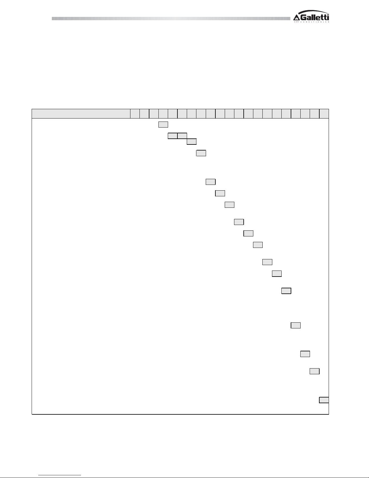
Serie Grandezza Organism o Notificato N° cert ificat o Procedura di v alutazione di conf orm ità Categoria PED M arcat ura
Range Size Notified body certificate Conformit y Compl iance Module PED category Mark ing
ECH
2
O - ECH2O H
4-5-6-7
1115 Modulo D1
I
CE
MCA - MCA H 10-12-14
1115 Modulo D1
I
CE
MCA - MCA H 16-21-25-30-37-50-60
1115 Modulo D1
II
CE + PED
LCA - LCA H 045-050-060-070-080-090- 105
1115 Modulo D1
II
CE + PED
MCC - MCC H 6-7-9-12-15
1115 Modulo D1
I
CE
MCC - MCC H 18-22-25-33-37
1115 Modulo D1
II
CE + PED
MCW - MCW / H 5-7-10-12-15
1115 Modulo D1
I
CE
MCW - MCW / H 18-20-22-27-31-39
1115 Modulo D1
II
CE + PED
MPE - MPEH - MCE - M CEH 4-5-7-8 1115 Modulo D1
I
CE
MPE - MPEH - MCE - M CEH 9-10-11-13-15-18 1115 Modul o D1
I
CE
MPE - MPEH - MCE - M CEH
19-20-21-23-24-26- 27-28-31-32-34-35-39-40
1115 Modulo D1
II
CE + PED
MPE - MPEH - MCE - M CEH T30-T34-T40-T45 1115 M odulo D1
II
CE + PED
MFE 5-6-8-11-13-16-17-20-23 1115 Modulo D1
I
CE
MXE 9-11-14-16 1115 M odu lo D1
I
CE
MXE 19-21 1115 Modulo D1
II
CE + PED
LCA - LCA H 115-130- 150-180-205-220-235-250-280-300
0398 B.05.0600AP -01 - 01-01-2005
Modulo D1
II
CE + PED
N°006 rev. 4 del 06/02/2008
LCA and LCA H (115-300) units are manufactured in the plants of Hiref S.p.a - Galletti Group, Viale Spagna 31/33 Tribano (Padova)
Bentivoglio, 16/07/2008
Galletti S.p.A.
Luigi Galletti
President
DECLARATION OF CONFORMITY
Galletti S.p.A., whose head office is located at 12/a Via Romagnoli 12/a Bentivoglio (Bologna) - Italy, hereby declares, under its own responsibility, that
the water chillers and heat pumps belonging to the series:
ECHO, ECHO H, MCA, MCA H, LCA, LCA H, MCC, MCC H, MCW, MCW-H, MPE, MPEH, MCE, MCEH, MFE and MXE, units intended for applications
in civil air conditioning systems, comply with the requirements of EEC Directives 98/37/CE, 89/336/CEE, 92/31/CEE, 93/68/CEE, 2006/95/CE,
97/23/CE (PED).
These units are the result of an assembly of components [compressors, brazed plate heat exchangers, liquid receivers, pipes, control and safety
valves] which are individually provided, where required, with certification in accordance with current directives: the category to which the machines
belong is determined on the basis of an analysis of the components subject to the PED and corresponds to the highest category among the
components used.
For each series of machines, the conformity of the assembly has been assessed by notified bodies, applying the assessment procedures (forms)
pursuant to annex II of the PED - Directive 97/23, as shown in the following table:

RG66004088 - Rev 00
All copying, even partial, of this manual is strictly forbidden.
MXE

RG66004088 - Rev 00
MXE
All copying, even partial, of this manual is strictly forbidden.
1 THE SERIES
Galletti has developed this product for the production of hot water for heating
systems - especially in demand for independent homes - with the aim of
reducing primary energy consumption and operating costs compared to
conventional gas or electric systems, thanks to a high level of efficiency:
average COP 3.33 (Eurovent Energy Efficiency Class A)
average EER 3.23 (Eurovent Energy Efficiency Class A)
OPTIMISED FOR OPERATION IN THE HEATING MODE
- Plate heat exchanger with reverse-flow operation in the heating mode
(+7% increase in efficiency).
- Finned coil with wide fin spacing
- Desuperheater in the pipes at the base of the finned block heat exchanger.
- Heating cable on the base in the internal part of the finned coil.
- Facilitated condensate drainage
YEAR-ROUND OPERATION
MXE heat pumps have been designed to work in the heating mode with
outdoor air temperatures ranging from -15°C to + 30°C, producing hot water
at temperatures of up to 55°C, and in the cooling mode with air temperatures
ranging from -10 to +45°C.
The electronic expansion valve and
condensation control (under pressure)
contribute to increasing the working range.
25
30
35
40
45
50
55
60
-15 -10 -5 0 5 10 15 20 25
Air temperature (°C)
Temperature of water produced (°C)
WORKING RANGE
MXE
SMART DEFROST SYSTEM
The exclusive defrost system (optional feature available with the advanced
controller) can correctly identify an impairment of per formance in the outdoor
exchanger due to the formation of ice and minimise the process time in
relation to normal operation of the unit.
SELF-ADAPTIVE
The electronic control system allows the setpoint to be adjusted automatically
according to the outdoor temperature in order to reduce consumption and
broaden the working temperature range.
The unit can also function in systems with a low water content, even
without the use of a storage reservoir, thanks to the automatic adjustment
which limits the number of compressor starts and thus extends the life of
the compressors themselves.

RG66004088 - Rev 00
All copying, even partial, of this manual is strictly forbidden.
MXE
2 CONSTRUCTIVE FEATURES
STRUCTURE
Painted galvanised sheet steel structure (RAL9002) for an attractive look and
effective resistance to corrosive agents.
Fastening devices are made of non-oxidizable materials, or carbon steel that
has undergone surface-passivating treatments.
The compressor compartment is completely sealed and may be accessed on
3 sides thanks to easy-to-remove panels that greatly simplify maintenance
and/or inspection.
Sound insulation, available on request, can further reduce the noise emissions
of the unit.
CUSTOMISED HYDRAULIC KIT
- High head pump made entirely of stainless steel, already configured for
use with mixtures of water and ethylene glycol up to 35% and provided
with internal thermal protection.
It is housed in the compressor compartment and is easy to reach thanks
to the removable perimeter panels.
- Expansion tank.
- Safety valve.
- Filling cock (included).
- Automatic vent valve.
- Water differential pressure switch and outlet water temperature probe with
anti-freeze thermostat function.
- Mechanical Y filter supplied as a standard feature on all models to protect
the evaporator (included).
- Buffer tank available on request.
COOLING CIRCUIT
- Scroll-type compressor housed in a compar tment that can be sound
insulated.
- Brazed plate heat exchangers made of STAINLESS STEEL and optimised
for use with R410A.
- Finned block condenser with 8 mm copper piping and aluminium fins,
characterised by ample heat exchange surfaces.
- Dehydrating filter.
- Flow indicator with humidity indicator.
- Electronically controlled electric thermostatic valve with dedicated driver
which controls opening according to the refrigerant pressure and
temperature downstream from the evaporator.
- Reverse cycle valve
- Single-acting valves.
- Liquid receiver.
- High and low pressure switches.
- Safety valve.
- Schrader valves for checks and/or maintenance.
- Refrigerant pressure gauges (optional)
FAN DRIVE ASSEMBLY
Electric fan with 6-pole external rotor motor directly keyed to the axial fan, with
internal thermal protection on the windings, complete with safety grille and
dedicated supporting structure.
The fan is housed in a special compartment having a profile designed to
optimise ventilation.
The use of finned block heat exchangers with 8mm diameter pipes reduces
pressure drops on the air side, thus significantly improving the noise levels of
the units.
The condensation control system continuously and automatically regulates
the fan speed, further limiting the noise emissions of the unit during nighttime
operation and under partial load conditions.
FINNED BLOCK HEAT EXCHANGER
Made of 8mm diameter copper pipes and aluminium fins, generously sized.
The special engineering of the heat exchangers allows defrost cycles to be
carried out at maximum speed in the models with heat pump operation, which
brings clear benefits in terms of the integrated efficiency of the whole cycle.
ELECTRONIC MICROPROCESSOR CONTROL
The electronic control enables the complete control of the MXE unit. It can be
easily accessed through a
polycarbonate flap with IP65 protection
rating.
The self-adaptive logic enables the unit
to operate even in systems where the
water content is low, without the use
of an inertial water storage reservoir.
By reading the outdoor air temperature, it can automatically change the setpoint to adapt it to the outdoor load
conditions or keep the unit running even in the harshest winter conditions.
The basic controller comes complete with the MODBUS protocol and enables
an immediate connection to ERGO networks.
Main functions
- Control over the temperature of water entering the evaporator.
- Defrosting management
- Control of fan speed
- Complete alarm management.
- Dynamic control of the setpoint according to the outdoor air temperature.
- Can be connected to an RS485 serial line for supervisory / teleassistance
operation;
- Option of connecting a remote terminal that duplicates the control
functions.
Devices controlled:
- Compressor
- Fans
- Reverse cycle valve
- Water circulation pump.
- Antifreeze heating elements
- Alarm signalling relay
On request, it is possible to install the advanced controller whose functions
extend to :
- LAN networks
- Smar t Defrost System
ELECTRIC CONTROL BOARD
The electric control board is constructed and wired in accordance with EEC
Directive 73/23, Directive 89/336 on electromagnetic compatibility and related
standards. Made of steel sheet, it is also protected by the enclosing panels of
the machine.
OPTIONS
Incorporable buffer tank
Low noise execution
Refrigerant pressure gauges
Antifreeze heating elements on the tank
Heat recovery 25% (chiller)
Special exchangers (hydrophilic treatment, copper-copper, cataphoresis, anticorrosion)
ACCESSORIES AVAILABLE
Remote control boards
Base vibration dampers
Metal grilles to protect exchangers
RG66004088 - Rev 00
MXE
All copying, even partial, of this manual is strictly forbidden.
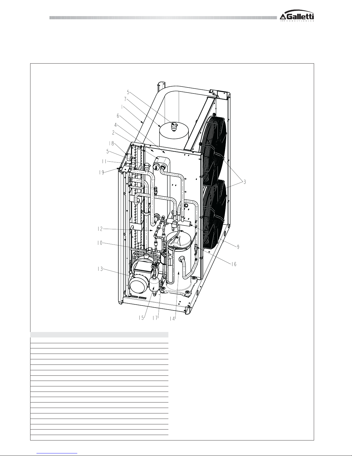
3 LAYOUT OF COMPONENTS
MXE 09 ÷ 16
LEGEND Description
1 R410A - air exchanger
2 R410A - water exchanger
3 Fans
4 Water differential pressure switch (fan compartment)
5 Automatic air vent valve
6 Expansion tank (fan compartment)
7 Buffer tank (accessory)
9 4-way valve
10 Thermostatic valve
11 Water safety valve
12 Liquid receiver (fan compartment)
13 Circulation pump
14 Compressor
15 Refrigerant filter
16 Low pressure switch and charge inlet
17 High pressure switch and charge inlet
18 Water pressure gauge
19 Water filling point
MXE 09 - 16

RG66004088 - Rev 00
All copying, even partial, of this manual is strictly forbidden.
MXE
3 LAYOUT OF COMPONENTS
MXE 19 ÷ 21
LEGEND Description
1 R410A - air exchanger
2 R410A - water exchanger
3 Fans
4 Water differential pressure switch (fan compartment)
5 Automatic air vent valve
6 Expansion tank (fan compartment)
7 Buffer tank (accessory)
9 4-way valve
10 Thermostatic valve
11 Water safety valve
12 Liquid receiver (fan compartment)
13 Circulation pump
14 Compressor
15 Refrigerant filter
16 Low pressure switch and charge inlet
17 High pressure switch and charge inlet
18 Water pressure gauge
19 Water filling point
MXE 19 - 21
RG66004088 - Rev 00
MXE
All copying, even partial, of this manual is strictly forbidden.
4 MODELS AND CONFIGURATIONS
FIELD OF APPLICATION
MXE heat pumps have been designed to heat water for air conditioning and heating systems intended for residential or commercial use.
MODELS AND VERSIONS
The MXE series features 6 models of varying capacity equipped with heat pump.
All models are charged with R410A refrigerant.
N.B. The choice of some options may preclude the choice of others or make some other fields become mandatory. Contact Galletti S.p.A. for verification
MX E 009H0A100CP1000001
0
0
09
H
H
0
0
M
2
4
A
A
1
1
0
0
S
0
0
C
C
P
P
S
1
1
0
0
M
0
0
2
S
M
X
0
O
R
C
B
0
0
G
Complete Unit Code
Operation
Single phase
400 - 3N - 50
Model (size)
Version
Single compressor
Heat pump
Powe r Suppl y
Single Phase + thermalmagnetic
400 - 3N - 50 + the rmal magnetic
Expansion Valve
Elect ronic expa nsi on valve
Not present
Condensing control
Present
Heat Recover
Pump and accessories
Pump - ves sel - wate r charge valve
Buffer tank
Not present
With modulating air flow
Antifreeze kit
Present, unit with pump and vessel
Present, unit with pump, vessel and tank
Acoustic insulation
Sound proofing insulation for compressor housing
Refrigerant ci rcuit accessoires
Not present
Refrigerant gauge
Protection grille
Not present
Remote control
Special coil
Standard
Copper / copper heat exchanger
Not present
RS485 port (modbus + carel protocol)
Simplified
Base microprocessor remote control (modbus excluded )
ADVANCED microprocessor remote control
Present
Cat ap hore sis
"Blygold"
0
0
1
2
3
1
1
2
Advanced microprocessor
Soft starter
Power factor correction capacitors + soft starter
Control panel
Basic microprocessor
Compressor options
Not present
Power factor correction capacitors

RG66004088 - Rev 00
All copying, even partial, of this manual is strictly forbidden.
MXE
5 TECHNICAL CHARACTERISTICS
5.1 RATED TECHNICAL DATA OF HEAT PUMPS
* Weights refer to model with pump and storage reservoir
- Cooling capacity: outdoor air temperature 35°C, water temperature 12°C / 7°C
- Heating capacity: outdoor air temperature 7°C dry bulb and 6.2°C wet bulb, water temperature 40°C/45°C
- Sound power measured according to standards ISO 3741 - ISO 3744 and EN 29614-1
- Sound pressure measured at a distance of 10 m and a height of 1.5 m above the ground in a clear field (fan side).
- The maximum electrical input is the mains electricity that must be available in order for the unit to work.
- The maximum current absorption refers to the current that will trigger the internal safety devices of the unit. It is the maximum current allowed in the unit.
This value may never be exceeded; it must be used as a reference for determining the size of the power supply line and the related safety devices (refer to the
wiring diagram supplied with the units).
MXE
009 M 009 011 M 011 014 016 019 021
Pow er s upply V-ph-H z 230-1-50 400-3-50 230-1-50 400-3-50 400-3-50 400-3-50 400-3-50 400-3-50
Cooling capacity kW 7,33 7,46 9,34 9,34 12,20 14,40 16,05 18,50
Total power input
kW 2,83 2,71 3,58 3,38 4,30 5,24 5,54 6,21
EER 2,98 3,19 2,91 3,10 3,10 2,96 3,10 3,17
ESEER 3,92 3,62 3,73 3,31 3,77 3,59 3,67 3,79
Heating capacity kW 8,54 8,46 10,82 10,51 13,66 15,84 18,53 20,64
Total power input in hea ti ng mode kW 3,15 2,99 3,72 3,47 4,47 5,24 5,71 6,31
COP 3,07 3,21 3,23 3,39 3,33 3,25 3,47 3,47
Ma ximum power i nput A 22,3 9,3 26,3 11,3 13,3 16,3 19,6 20,0
Starting absorbed current A 84 37 98 50 66 72 77 103
n° of scroll compressor / circuits 1/1 1/1 1/1 1/1 1/1 1/1 1/1 1/1
Low/high pr essure switch bar 0,7 / 42 0,7 / 42 0,7 / 42 0,7 / 42 0,7 / 42 0,7 / 42 0,7 / 42 0,7 / 42
n° of axial fan 22222244
Air flow
m
3
/h
7.705 7.705 7.705 7.705 7.355 7.355 12.679 12.679
Water fl ow in cooling mode l/ h 1.261 1.283 1.606 1.606 2.098 2.477 2.761 3.182
Water fl ow in he at pum p l/ h 1.469 1.454 1.861 1.821 2.442 2.853 3.211 3.605
Di ame te r of hydrualic connections " 1 1/4 1 1/4 1 1/4 1 1/4 1 1/4 1 1/4 1 1/ 4 1 1/4
Avai l able pressure head (cooling) kP a 130 130 132 132 115 111 154 157
Avai l able pressure head (he ating) kPa 118 118 121 125 103 98 143 148
Expansion tank
dm
3
55555555
Buffer tank
dm
3
30 30 30 30 30 30 30 50
Height
mm 1250 1250 1250 1250 1250 1250 1275 1275
Length mm 1220 1220 1220 1220 1220 1220 1590 1590
Depth mm 550 550 550 550 550 550 600 600
Sound powe r lev el dB(A) 69 69 69 69 69 69 72 72
Sound pr ess ur e lev el dB(A) 41 41 41 41 41 41 44 44
Transport we ight * kg
212 212 215 215 219 220 273 273
Operating weight * kg
237,5 237,5 240,5 240,5 244,5 245,5 309,3 309,3
RG66004088 - Rev 00
MXE
All copying, even partial, of this manual is strictly forbidden.
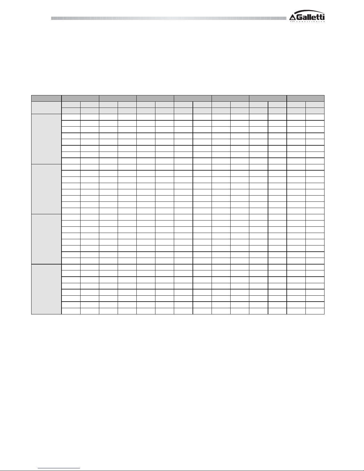
6 PERFORMANCE
6.1 MXE COOLING CAPACITIES
Tbs
1
Air inlet temperature (dry bulb)
Tw in/out Water inlet/outlet temperature
PF Cooling capacity
PA Total power input including pump
Tw inTw outPFPAPFPAPFPAPFPAPFPAPFPA
[°C] [°C] kW kW kW kW kW kW kW kW kW kW kW kW
10 5 8,1 2,15 7,8 2,29 7,32 2,53 6,84 2,82 6,34 3,15 5,82 3,52
11 6 8,4 2,15 8,1 2,30 7,57 2,54 7,08 2,82 6,56 3,15 6,02 3,53
12 7 8,7 2,14 8,3 2,30 7,8 2,54 7,32 2,82 6,79 3,15 6,23 3,53
13 8 9,0 2,13 8,6 2,30 8,1 2,54 7,57 2,83 7,02 3,16 6,44 3,54
14 9 9,3 2,13 8,9 2,31 8,4 2,55 7,8 2,83 7,25 3,17 6,66 3,54
15 10 9,7 2,12 9,2 2,31 8,6 2,55 8,1 2,84 7,49 3,17 6,88 3,55
16 11 10,0 2,12 9,5 2,32 8,9 2,56 8,3 2,85 7,74 3,18 7,11 3,55
17 12 10,3 2,12 9,8 2,32 9,2 2,57 8,6 2,86 7,99 3,19 7,34 3,56
10 5 8,6 2,08 8,2 2,21 7,62 2,43 7,03 2,70 6,40 3,01 5,74 3,36
11 6 8,8 2,07 8,4 2,21 7,85 2,44 7,24 2,70 6,60 3,01 5,93 3,36
12 7 9,1 2,06 8,7 2,21 8,1 2,44 7,45 2,70 6,81 3,01 6,12 3,36
13 8 9,4 2,06 8,9 2,22 8,3 2,44 7,67 2,71 7,01 3,02 6,31 3,37
14 9 9,6 2,05 9,1 2,22 8,5 2,45 7,9 2,71 7,20 3,02 6,50 3,37
15
10
9,9 2,04 9,3 2,22 8,7 2,45 8,1 2,72 7,40 3,03 6,69 3,37
16 11 10,2 2,04 9,6 2,23 8,9 2,46 8,3 2,73 7,59 3,03 6,87 3,38
17 12 10,4 2,04 9,8 2,24 9,2 2,47 8,5 2,73 7,78 3,04 7,05 3,38
10 5 10,5 2,81 9,9 3,05 9,3 3,34 8,7 3,69 8,00 4,10 7,31 4,57
11 6 10,8 2,82 10,2 3,06 9,6 3,36 9,0 3,71 8,27 4,12 7,55 4,59
12 7 11,2 2,83 10,6 3,07 9,9 3,37 9,3 3,73 8,5 4,14 7,80 4,62
13 8 11,6 2,84 10,9 3,08 10,3 3,39 9,6 3,75 8,8 4,16 8,05 4,64
14 9 11,9 2,85 11,3 3,10 10,6 3,40 9,9 3,76 9,1 4,19 8,30 4,67
15 10 12,3 2,86 11,6 3,11 10,9 3,42 10,2 3,78 9,4 4,21 8,56 4,69
16 11 12,7 2,87 12,0 3,12 11,3 3,43 10,5 3,80 9,7 4,23 8,8 4,72
17 12 13,1 2,88 12,4 3,14 11,6 3,45 10,8 3,82 10,0 4,26 9,1 4,75
10 5 10,6 2,52 10,0 2,76 9,4 3,04 8,7 3,36 8,0 3,72 7,3 4,12
11 6 11,0 2,53 10,3 2,77 9,7 3,05 9,0 3,38 8,3 3,74 7,6 4,14
12 7 11,3 2,54 10,7 2,78 10,0 3,07 9,3 3,39 8,6 3,76 7,8 4,16
13 8 11,7 2,55 11,0 2,80 10,3 3,08 9,6 3,41 8,8 3,78 8,1 4,19
14 9 12,0 2,56 11,4 2,81 10,6 3,10 9,9 3,43 9,1 3,80 8,3 4,21
15 10 12,4 2,57 11,7 2,82 11,0 3,12 10,2 3,45 9,4 3,82 8,6 4,23
16 11 12,8 2,58 12,1 2,84 11,3 3,13 10,5 3,47 9,7 3,84 8,9 4,25
17 12 13,2 2,59 12,4 2,85 11,7 3,15 10,8 3,49 10,0 3,86 9,1 4,28
45
MXE 009 M
MXE 009
MXE 011 M
Tbs
1
25 3020 35 40
MXE 011
RG66004088 - Rev 00
All copying, even partial, of this manual is strictly forbidden.
MXE
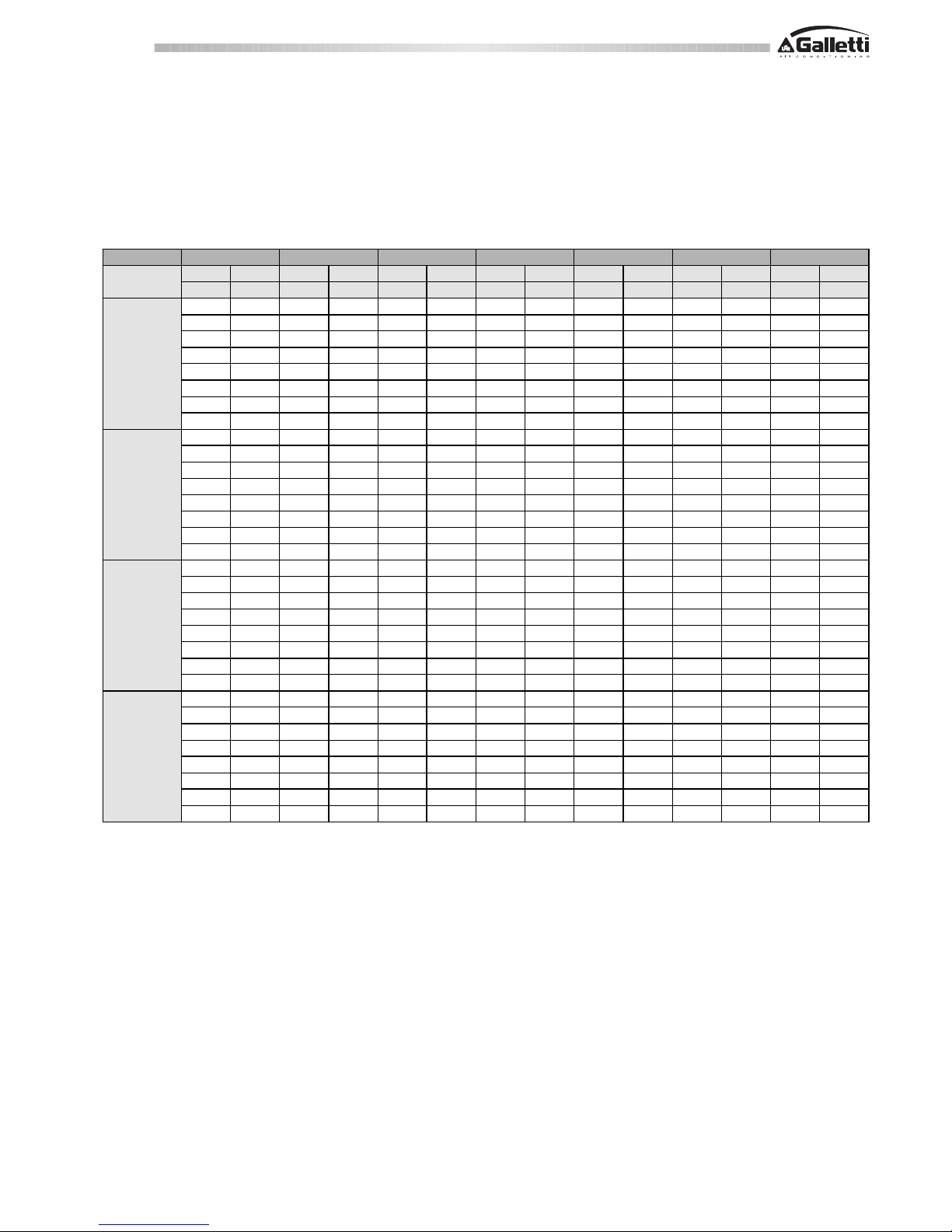
6 PERFORMANCE
6.1 MXE COOLING CAPACITIES
Tbs
1
Air inlet temperature (dry bulb)
Tw in/out Water inlet/outlet temperature
PF Cooling capacity
PA Total power input including pump
Tw inTw outPFPAPFPAPFPAPFPAPFPAPFPA
[°C] [°C] kW kW kW kW kW kW kW kW kW kW kW kW
10 5 13,6 3,12 13,0 3,43 12,2 3,81 11,4 4,27 10,5 4,81 9,6 5,43
11 6 14,1 3,13 13,4 3,44 12,6 3,83 11,8 4,29 10,9 4,83 9,9 5,45
12 7 14,5 3,14 13,8 3,46 13,0 3,85 12,1 4,32 11,2 4,86 10,2 5,47
13 8 15,0 3,16 14,2 3,48 13,4 3,88 12,5 4,34 11,6 4,88 10,5 5,49
14 9 15,4 3,17 14,7 3,50 13,8 3,90 12,9 4,37 11,9 4,91 10,9 5,51
15 10 15,9 3,19 15,1 3,53 14,2 3,93 13,3 4,40 12,3 4,93 11,2 5,54
16 11 16,4 3,21 15,5 3,55 14,6 3,96 13,7 4,43 12,6 4,96 11,6 5,56
17 12 16,9 3,23 16,0 3,58 15,0 3,99 14,1 4,46 13,0 5,00 11,9 5,59
10 5 16,4 3,82 15,5 4,19 14,5 4,63 13,5 5,12 12,4 5,67 11,2 6,28
11 6 16,9 3,84 16,0 4,22 15,0 4,66 13,9 5,16 12,8 5,71 11,6 6,33
12 7 17,5 3,87 16,5 4,26 15,5 4,70 14,4 5,20 13,2 5,75 12,0 6,37
13 8 18,0 3,90 17,0 4,29 16,0 4,73 14,8 5,24 13,6 5,80 12,4 6,42
14 9 18,5 3,93 17,5 4,32 16,4 4,77 15,3 5,28 14,1 5,84 12,8 6,46
15 10 19,1 3,97 18,1 4,36 16,9 4,81 15,7 5,32 14,5 5,89 13,2 6,51
16 11 19,7 4,00 18,6 4,40 17,4 4,85 16,2 5,36 14,9 5,93 13,6 6,56
17 12 20,2 4,04 19,1 4,44 17,9 4,89 16,7 5,41 15,4 5,98 14,0 6,61
10 5 17,9 4,20 17,1 4,53 16,1 4,96 15,0 5,46 14,0 6,03 12,8 6,67
11 6 18,5 4,21 17,6 4,55 16,6 4,99 15,5 5,49 14,4 6,06 13,3 6,71
12 7 19,2 4,22 18,2 4,58 17,1 5,01 16,0 5,52 14,9 6,10 13,7 6,75
13 8 19,8 4,24 18,8 4,61 17,7 5,04 16,6 5,55 15,4 6,14 14,1 6,79
14 9 20,4 4,27 19,4 4,63 18,3 5,07 17,1 5,59 15,9 6,17 14,6 6,83
15 10 21,1 4,29 20,0 4,66 18,8 5,11 17,6 5,62 16,3 6,21 15,0 6,87
16 11 21,7 4,32 20,6 4,69 19,4 5,14 18,2 5,66 16,9 6,25 15,5 6,92
17 12 22,4 4,35 21,2 4,73 20,0 5,17 18,7 5,70 17,4 6,29 15,9 6,96
10 5 20,8 4,57 19,7 4,99 18,6 5,49 17,4 6,08 16,1 6,74 14,8 7,5
11 6 21,5 4,60 20,4 5,03 19,2 5,53 17,9 6,12 16,6 6,79 15,3 7,5
12 7 22,2 4,64 21,0 5,07 19,8 5,58 18,5 6,17 17,2 6,84 15,8 7,6
13 8 22,9 4,68 21,7 5,11 20,4 5,62 19,1 6,21 17,7 6,9 16,3 7,6
14 9 23,6 4,72 22,4 5,15 21,1 5,67 19,7 6,26 18,3 6,9 16,8 7,7
15 10 24,3 4,76 23,1 5,20 21,8 5,71 20,4 6,31 18,9 7,0 17,4 7,7
16 11 25,1 4,81 23,8 5,24 22,4 5,76 21,0 6,36 19,5 7,0 17,9 7,8
17 12 25,8 4,86 24,5 5,29 23,1 5,81 21,7 6,41 20,1 7,1 18,5 7,9
MXE 019
MXE 021
MXE 014
MXE 016
Tbs
1
20 25 30 35 40 45

RG66004088 - Rev 00
MXE
All copying, even partial, of this manual is strictly forbidden.
6 PERFORMANCE
6.2 MXE HEATING CAPACITIES
Tbs
1
Air inlet temperature (dry bulb)
Tw in/out Water inlet/outlet temperature
PT Heating capacity
PA Total power input including pump
RH Relative humidity
Tw inTw outPTPAPTPAPTPAPTPAPTPAPTPA
[°C] [°C] kW kW kW kW kW kW kW kW kW kW kW kW
25 30 3,65 2,45 5,62 2,37 7,43 2, 32 9,2 2,29 10,3 2,28 11,1 2,27
30 35 3,64 2,72 5,58 2,63 7,29 2, 57 8,9 2,53 10,0 2,51 10,8 2,50
35 40 3,65 3,02 5,57 2,93 7,18 2, 86 8,7 2,81 9,7 2,79 10,5 2,78
40 45 - - 5,58 3,28 7,08 3,20 8,5 3,14 9,5 3,12 10,1 3,10
4550------8,33,519,23,489,83,47
5055--------9,03,909,63,88
25 30 3,18 2,35 5,67 2,31 7,77 2, 25 9,5 2,21 10,5 2,19 11,1 2,18
30 35 3,11 2,60 5,49 2,55 7,49 2, 48 9,1 2,43 10,1 2,41 10,7 2,40
35 40 3,01 2,87 5,30 2,83 7,22 2, 75 8,8 2,69 9,7 2,67 10,3 2,66
40 45 - - 5,11 3,16 6,95 3,07 8,5 3,00 9,3 2,97 9,9 2,96
4550------8,13,368,93,329,53,30
5055--------8,63,709,03,67
25 30 4,62 2,92 7,15 2,89 9,50 2, 88 11,8 2,88 13,3 2, 88 14,3 2,87
30 35 4,59 3,21 7,05 3,16 9,29 3, 15 11,5 3,14 12,9 3, 13 13,9 3,13
35 40 4,50 3,47 6,96 3,47 9,11 3, 46 11,2 3,45 12,5 3, 45 13,4 3,44
40 45 - - 6,89 3,81 8,95 3,82 10,9 3,82 12,1 3, 82 13,0 3,81
4550------10,64,2511,84,2412,64,24
5055--------11,44,7312,24,73
25 30 4,46 2,54 6,96 2,61 9,29 2, 61 11,6 2,60 13,0 2, 59 14,0 2,58
30 35 4,35 2,78 6,81 2,86 9,04 2, 86 11,2 2,85 12,6 2, 84 13,5 2,84
35 40 4,34 3,04 6,70 3,13 8,80 3, 14 10,9 3,14 12,1 3, 14 13,1 3,14
40 45 - - 6,62 3,45 8,59 3,47 10,5 3,47 11,7 3, 47 12,6 3,47
4550------10,23,8511,33,8512,23,85
5055--------11,04,2611,74,26
25 30 5,94 3,23 9,12 3,26 11,94 3,24 14,7 3,23 16,4 3, 23 17,6 3,24
30 35 5,91 3,63 9,04 3,64 11,74 3,59 14,3 3,57 16,0 3, 57 17,1 3,59
35 40 6,03 4,07 8,99 4,09 11,54 4,03 14,0 3,99 15,5 3, 99 16,7 4,00
40 45 - - 8,97 4,61 11,34 4,54 13,7 4,48 15,1 4,47 16,2 4,48
4550------13,35,0614,75,0315,75,02
5055--------14,35,6615,25,63
25 30 6,83 3,70 10,58 3,83 14,03 3,89 17,4 3,93 19,5 3,96 21,0 3,99
30 35 6,77 4,11 10,35 4,22 13,70 4,28 16,9 4,32 19,0 4,36 20,4 4,38
35 40 6,62 4,53 10,11 4,66 13,36 4,73 16,5 4,78 18,4 4,81 19,8 4,83
40 45 - - 9,86 5,14 13,02 5,23 16,0 5,29 17,9 5,32 19,2 5,35
4550------15,55,8617,35,9018,55,9
5055--------16,76,5317,96,6
25
30 7,96 4, 23 12,47 4,31 16,53 4, 37 20,4 4,43 23,0 4,48 24,8 4,51
30 35 7,83 4,62 12,26 4,73 16,14 4,79 19,8 4,84 22,3 4,88 24,0 4,92
35 40 7,74 5,03 12,06 5,19 15,75 5,26 19,3 5,33 21,6 5,37 23,2 5,40
40 45 - - 11,86 5,70 15,38 5,80 18,7 5, 9 20,9 5,9 22,4 6, 0
4550------18,16,520,26,621,66,6
5055--------19,57,320,87,3
25 30 8,00 4,36 13,60 4,53 18,17 4,63 22,6 4,74 25,3 4,8 27,4 4,9
30 35 7,95 4,86 13,30 5,02 17,68 5,11 21,9 5,2 24,6 5,3 26,5 5, 3
35 40 7,90 5,38 13,05 5,56 17,23 5,65 21,3 5,7 23,8 5,8 25,7 5, 9
40 45 - - 12,83 6,16 16,82 6,28 20,6 6, 4 23,1 6,4 24,8 6, 5
4550------20,07,122,37,124,07,2
5055--------21,67,923,27,9
MXE 009
MXE 011 M
MXE 019
MXE 016
MXE 014
MXE 011
20°C / 70 %7 °C / 88 % 15 °C / 80 %
MXE 021
Tbs
1
/ RH -5 °C / 90 % 0 °C / 90 %-10 °C
MXE 009 M

RG66004088 - Rev 00
All copying, even partial, of this manual is strictly forbidden.
MXE
6 PERFORMANCE
6.3 INTEGRATED CAPACITIES
In the heat pump operation (heating mode), the actual heating capacities of units may be lower than the values shown in the table, due to defrosting
cycles. To obtain the actual heating capacity, multiply the capacity values by the corrective coefficients given below.
7 SOUND LEVEL
LEGEND:
LpATotal sound pressure level, weighted A, measured in an open field, at a distance of 10 m, with a directivity factor of 2.
Lw Sound power level by octave band, not weighted
LwATotal sound power level, weighted A
-5 0 5 >5
P
chiller2 0,91 0,9 0,95 1
PCO XS 0,92 0,97 0,95 1
Control
Air temperature dry bulb (°C)
Lw
A
Lp
A
125 Hz 250 Hz 500 Hz 1000 Hz 2000 Hz 4000 Hz 8000 Hz Total Total
dB dB dB dB dB dB dB dB (A) dB (A)
MXE 009M 74,8 68,5 67,9 63,8 56,6 51,6 47,8 69 41
MXE 009 74,8 68,5 67,9 63,8 56,6 51,6 47,8 69 41
MXE 011M 74,8 68,5 67,9 63,8 56,6 51,6 47,8 69 41
MXE 011 74,8 68,5 67,9 63,8 56,6 51,6 47,8 69 41
MXE 014 75,3 69,0 68,4 64,3 57,1 52,1 48,3 69 41
MXE 016 75,3 69,0 68,4 64,3 57,1 52,1 48,3 69 41
MXE 019 77,8 71,5 70,9 66,8 59,6 54,6 50,8 72 44
MXE 021 78,3 72,0 71,4 67,3 60,1 55,1 51,3 72 44
Model
Lw

RG66004088 - Rev 00
MXE
All copying, even partial, of this manual is strictly forbidden.
8 OPERATING LIMITS
The graphs below illustrate the operating limits of MXE (in the case of continuous operation) in relation to the outlet water temperature and outdoor air temperature.
1 For transitory periods (e.g. equipment start up) values up to 25 °C are allowed
2 Value that may be reached only for outdoor air temperatures exceeding 0°C.
3 With condensation control: outdoor air T min - 15°C
Warning!
The units are designed to work with water and air temperatures falling within the range defined by the operating limits.
Attempting to operate the units beyond these limits could cause irreparable damage to the units themselves.
8.1 OPERATING LIMITS IN CHILLER MODE
TBS1Outdoor temperature (dry bulb)
Tw
2
Outlet water temperature
OPERATING LIMITS CHILLER HEAT PUMP
MIN MAX MIN MAX
Inlet water temperature (°C) 12 24 39 51
Outlet water temperature (°C) 7 19 27 57
Thermal differential of water (°C) 5836
Outdoor air temperature (°C) -10 48 -15 22
-15
-10
-5
0
5
10
15
20
25
30
35
40
45
50
6 8 10 12 14 16 18 20
TW2 (°C)
Tbs
1
(°C)

RG66004088 - Rev 00
All copying, even partial, of this manual is strictly forbidden.
MXE
6.3 THERMAL CARRIER FLUID
The units belonging to the MxE series can work with mixtures of water and up
to 30% ethylene glycol.
9 CALCULATION FACTORS
9.1 CHANGE IN OPERATING PARAMETERS WITH ΔT OTHER THAN
5°C
After identifying the unit’s per formance in the terms of the desired outlet water
temperature, correct the value by multiplying it by the following corrective
coefficients.
DT
W
C
PF/PT
C
PA
C
Qw
C
Dpw1
3 0,975 1 1,63 2,64
4 0,99 1 1,24 1,53
51111
6 1,015 1 0,85 0,72
7 1,03 1 0,74 0,54
8 1,04 1 0,65 0,42
LEGEND
DTWDifference between water inlet temperature and water outlet temperature
C
PF/PT
Corrective coefficient of cooling/heating capacity
C
PA
Correction coefficient of electrical input
C
Qw
Correction coefficient of water flow rate
C
Dpw1
Correction coefficient of pressure drop
8 OPERATING LIMITS
8.2 OPERATING LIMITS IN HEAT PUMP MODE
TBS1Outdoor temperature (dry bulb)
Tw
2
Outlet water temperature
9.2 WATER AND GLYCOL MIXTURE
Based on the minimum outlet water temperature, you can derive the percentage
of ethylene glycol and the corrective coefficient using the table below.
Percentage of ethylene glycol 0% 10% 20% 30 % 40%
Minimum temp. of water produced 5°C 2°C -5°C -10°C -15°C
Mixture freezing temp. (°C) 0°C -4°C -14°C -18°C -24°C
Capacity correction factor 1,000 0,998 0,994 0,989 0,983
Water flow rate correction factor 1,000 1,047 1,094 1,140 1,199
Pressure drop correction factor 1,000 1,157 1,352 1,585 1,860
WARNING:
The use of propylene glycol is not admitted with standard pumps.
For further information, contact the manufacturer.
20
25
30
35
40
45
50
55
60
-20-15-10-5 0 5 10152025
Tbs1 (°C)
TW
2
(°C)

RG66004088 - Rev 00
MXE
All copying, even partial, of this manual is strictly forbidden.
10 PRESSURE DROPS
The diagram shows the evaporator pressure drops (Dp) as a function of the
water flow rate (Qw), assuming an average water temperature of 10°C.
10.1 PRESSURE DROPS ON THE WATER SIDE
10.2 PRESSURE DROPS OF Y FILTER
The diagram shows the Y filter pressure drops (Dp) as a function of the water
flow rate (Qw), assuming an average water temperature of 10°C.
MXE 09 ÷ 21
MXE 09 ÷ 21
4Z>OK@
'
S>N3D@
0;(
RG66004088 - Rev 00
All copying, even partial, of this manual is strictly forbidden.
MXE
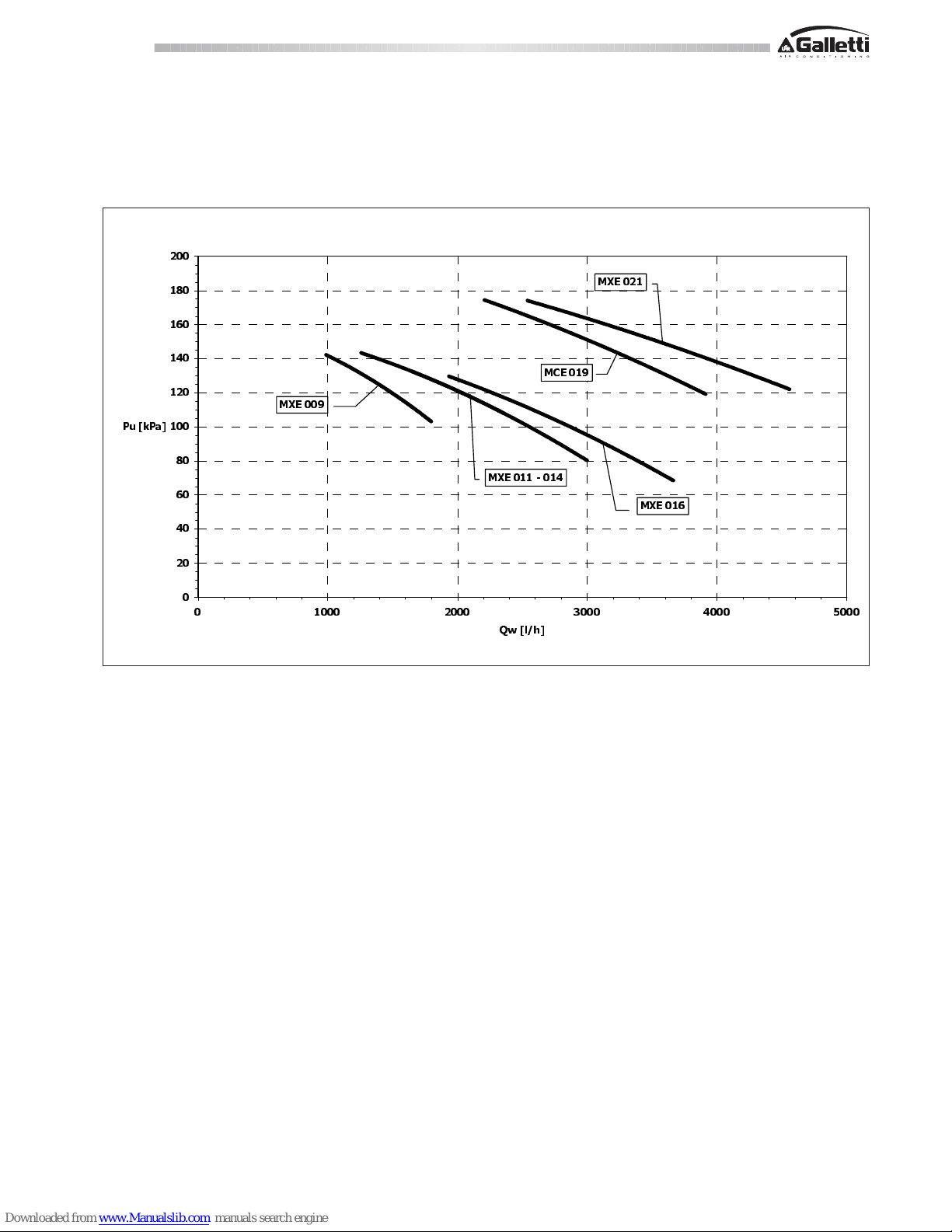
11 AVAILABLE HEAD OF THE UNIT
The diagram below shows the available head (Pu) of the unit as a function of
the water flow rate (Qw), assuming an average water temperature of 10°C, net
of pressure drops.
Pressure drops of the Y filter are not counted.
MXE 09 ÷ 21
4Z>OK@
3X>N3D@
0&(
0;(
0;(
0;(
0;(

RG66004088 - Rev 00
MXE
All copying, even partial, of this manual is strictly forbidden.
12 WATER CIRCUIT
When setting up the water circuit of the unit, it is advisable to follow the directions
below and in any case comply with local or national regulations.
Connect the pipes to the chiller using flexible couplings to prevent the
transmission of vibrations and to compensate thermal expansions.
It is recommended to install the following components on the pipes:
- Temperature and pressure indicators for routine maintenance and monitoring of the unit. Checking the pressure on the water side will enable you to
verify whether the expansion tank is working efficiently and to promptly detect
any water leaks within the equipment.
- Traps on incoming and outgoing pipes for temperature measurements,
which can provide a direct reading of the operating temperatures.
- Regulating valves (gate valves) for isolating the unit from the water circuit.
- Metal mesh filter (supplied), with a mesh size no greater than 1 mm,
to be fitted on the inlet pipe to protect the exchanger from scale or
impurities present in the pipes.
- Air vent valves, to be placed at the highest points of the water circuit for the
purpose of bleeding air. (The internal pipes of the unit are fitted with small
air vent valves for bleeding the unit itself: this operation may only be carried
out when the unit is disconnected from the power supply).
- Drainage valve and, where necessary, a drainage tank for emptying out the
equipment for maintenance purposes or when the unit is taken out of service
at the end of the season. (A 1” drainage valve is provided on the optional
water buffer tank: this operation may only be carried out when the unit is
disconnected from the power supply).
It is of fundamental importance that the incoming water supply is hooked up
to the connection marked “Water Inlet”.
Otherwise the evaporator would be exposed to the risk of freezing since the
antifreeze thermostat would not be able to perform its function; moreover the
reverse cycle would not be respected in the cooling mode, resulting in additional
risks of malfunctioning.
The dimensions and position of plumbing connections are shown in the
dimension tables at the end of the manual.
The water circuit must be set up in such a way as to guarantee that the nominal
flow rate of the water supplied to the evaporator remains constant (+/- 15%)
in all operating conditions.
A standard feature of MXE units is a device for controlling the flow rate (flow
switch or differential pressure switch) in the water circuit in the immediate
vicinity of the evaporator.
12.1 SYSTEM WATER CONTENT AND CHARGING OF
EXPANSION TANK
In models without a water storage tank it is necessary to assure that the content
of water within the system does not fall below 4.5 litres/kW. This level is
necessary to prevent the water temperature from falling below the indoor unit
enabling threshold during defrost cycles.
N.B kW in reference to rated capacity
The expansion tank is pre-charged to a pressure of 1.5 bars, sufficient for
systems with a maximum height difference (H in the figure at the side) of 13
metres.
For greater height differences, refer to the table below in order to adjust the
charging pressure of the expansion tank accordingly.
In no case should you exceed the maximum height difference Hmax = 35 m.
Hmax=35 m
LEGEND
H Height difference of system
p
i
Charging pressure of expansion tank
C
max
Maximum system water content
Models
H
(m)
p
i
(bar)
C
max
(l)
<13 1,5 145
15 1,7 133
20 2,2 105
25 2,7 77
30 3,1 49
MXE 009-021

RG66004088 - Rev 00
All copying, even partial, of this manual is strictly forbidden.
MXE
12 WATER CIRCUIT
MXE (EVAPORATOR AND PUMP)
PLUMBING DIAGRAMS
MXE (EVAPORATOR, PUMP AND TANK)
OPZIONALE
OPTIONAL
OPZIONALE
OPTIONAL
LEGEND
VS Safety valve
EV Evaporator
PD Differential pressure switch
MA Water pressure gauge
VAS Air vent valve
SA Buffer tank
VE Expansion tank
P Pump
RS Drainage valve
RC Water filling cock
RG66004088 - Rev 00
MXE
All copying, even partial, of this manual is strictly forbidden.
13 ELECTRICAL DATA AND CONNECTIONS
- The maximum electrical input is the mains electricity that must be available in order for the unit to work.
- The maximum current absorption refers to the current that will trigger the internal safety devices of the unit.
It is the maximum current allowed in the unit. This value may never be exceeded; it must be used as a reference for determining the size of the power supply
line and the related safety devices (refer to the wiring diagram supplied with the units).
Cross-section area of cables: 4 A/mm2 approx.
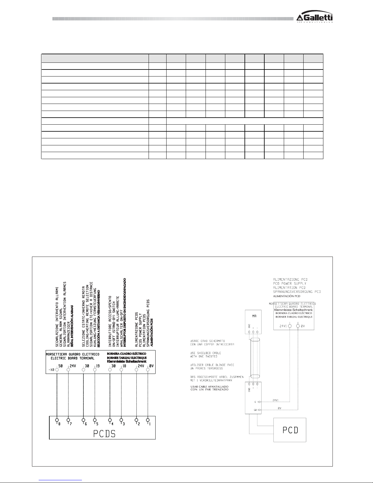
DIAGRAM SHOWING ELECTRICAL CONNECTIONS BETWEEN MXE AND PCDS / PCD REMOTE CONTROL PANEL
Use cabo blindado com
um par trançado
Alimentação PCD
Placa de bornes do quadro eléctrico
Sinalização intervenção alarmes
Selecção verão/inverno remota
Interruptor aceso/apagado
Alimentação PCDS
Note: Should the unit go into an alarm status, a voltage of 24V will be present
on the terminals of the electric control panel; where an interface with a voltagefree contact is desired, a relay must be fitted by the installer.
MXE
009 M 009 011 M 011 014 016 019 021
Maximum power input kW
4,0 3,9 4,9 4,6 6,0 6,6 7,3 8,2
Maximum current absorption A
22,0 9,0 26,0 11,0 13,0 16,0 20,0 21,0
Starting absorbed current A
84 37 99 50 66 72 77 103
Fan motor rated power kW
0,14 0,14 0,14 0,14 0,14 0,14 0,14 0,14
Fan motor rated current A
0,6 0,6 0,6 0,6 0,6 0,6 0,6 0,6
Pump motor rated power kW
22222222
Pump motor rated current A
230-1-50 400-3N -50 230-1-50 400-3N-50 400-3N -50 400-3N -50 400-3N-50 400-3N-50
Power supply V/f/Hz
230-1-50 400-3N -50 230-1-50 400-3N-50 400-3N -50 400-3N -50 400-3N-50 400-3N-50
Auxiliary powe r supply V/f/Hz
Power cables
mm
2
64644466
PCD connecting cables
mm
2
AWG22 AWG22 AWG22 AWG22 AWG22 AWG22 AWG22 AWG22
PCDS connecting cables
mm
2
11111111
Safety fuse F A
25 16 32 16 20 20 25 25
Circuit breaker IL A
25 16 32 16 20 20 25 25
230-1-50
RG66004088 - Rev 00
All copying, even partial, of this manual is strictly forbidden.
MXE
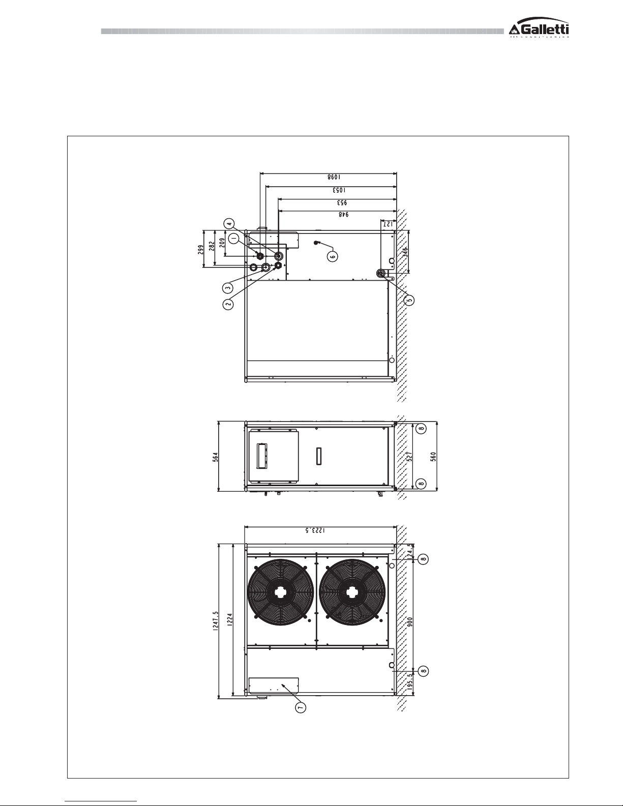
14 OVERALL DIMENSIONS MXE 09 ÷ 16
Legend:
1 Water inlet 1" ¼ female
2 Water outlet 1" ¼ female
3 Safety valve discharge outlet provided with rubber ring holder
4 Water supply ½” male (optional tap)
5 Water drainage ½” female
6 Power supply Ø 28 mm
7 Electric control board
8 Fastening points for vibration dampers (accessory)

RG66004088 - Rev 00
MXE
All copying, even partial, of this manual is strictly forbidden.
14 OVERALL DIMENSIONS MXE 19 ÷ 21
Legend:
1 Water inlet 1" ¼ female
2 Water outlet 1" ¼ female
3 Safety valve discharge outlet provided with rubber ring holder
4 Water supply ½” male (optional tap)
5 Water drainage ½” female
6 Power supply Ø 28 mm
7 Electric control board
8 Fastening points for vibration dampers (accessory)

RG66004088 - Rev 00
All copying, even partial, of this manual is strictly forbidden.
MXE
15 INSTALLATION CLEARANCE REQUIREMENTS
To guarantee the proper functioning of the unit and access for maintenance
purposes, it is necessary to comply with the minimum installation clearance
requirements shown in figures 1 and 2.
There must be no obstacles blocking the path of the air flow from the fans.
Avoid any and all situations of backflow of hot air between air outlet and inlet
of the unit.
If even only one of the above conditions is not fulfilled, please contact the
manufacturer to check for feasibility.
1
MXE 09 ÷ 16
In the design of the MXE series, special care has been taken to minimise noise
and vibrations transmitted to the ground.
Even greater insulation may be obtained, however, by using vibration damping
base supports (available as optional accessories).
If vibration damping base supports are adopted, it is strongly recommended
also to use vibration damping couplings on the water pipes.
Whenever the unit is to be sited on unstable ground (various types of soil,
gardens, etc.) it is a good idea to provide a supporting base of adequate
dimensions.
Warning:
heat pump units produce condensation while operating
in the heating mode.
QUADRO ELETTRICO
ELECTRICAL BOX
LATO BATTERIA
EXCHANGER SIDE
LATO ATTACCHI IDRAULICI BATTERIA
HEAT EXCHANGER WATER CONNECTION SIDE
1 m
1,5 m
1,5 m
MXE 19 ÷ 21
LATO ATTACCHI IDRAULICI BATTERIA
HEAT EXCHANGER WATER CONNECTION SIDE
QUADRO ELETTRICO
ELECTRICAL BOX
LATO BATTERIA
EXCHANGER SIDE
1 m
1,5 m
1,5 m
2
RG66004088 - Rev 00
MXE
All copying, even partial, of this manual is strictly forbidden.
16 SITING
It is important to bear in mind the following aspects when choosing the best
site for installing the unit:
- size and origin of water pipes;
- location of the power supply;
- solidity of the supporting surface;
- avoid obstacles to the outflow of air from the fan which could cause back
suction (see section on “installation clearance requirements”);
- direction of prevalent winds: (position the unit so that prevalent winds do
not alter the fan air flow).
A prevalent wind blowing from a direction opposite to the fan air flow will
reduce the maximum air temperature to a lower value than specified in the
operating limits,
a wind blowing in the same direction as the fan air flow will increase the minimum
air temperature to a higher value than specified in the operating limits.
Also in the heat pump mode, wind may have the effect of reducing the unit’s
operating range.
- avoid the possible reverberation of sound waves (do not install the unit in
narrow or cramped spaces).
- ensure adequate accessibility for maintenance or repairs (see section on
“installation clearance requirements”).
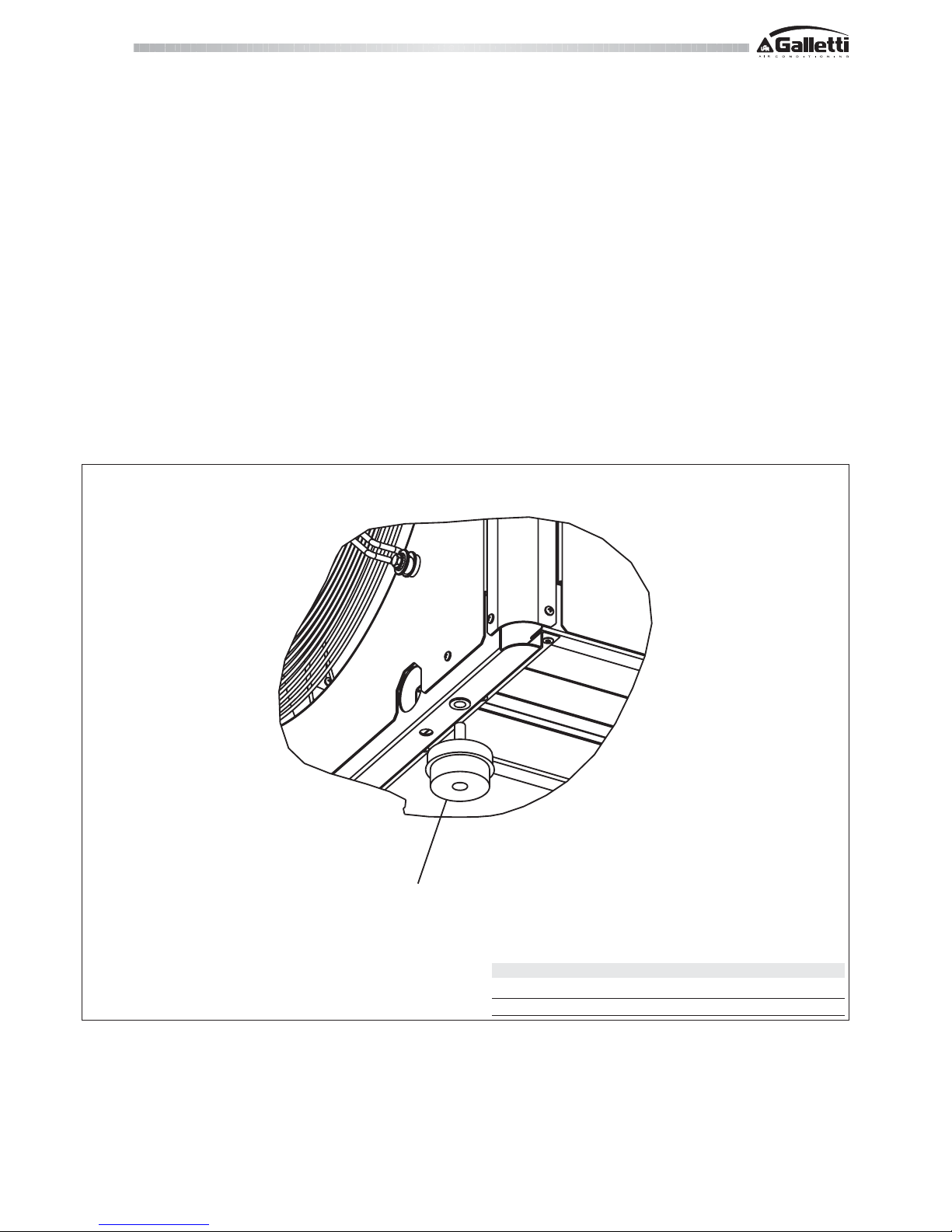
16.1 POSITIONING OF VIBRATION DAMPERS (ACCESSORY)
Dampers
MXE CODE NO. OF VIBRATION DAMPERS
09 -16 RYPAMCA10 4
19 - 21 RYPAMCA10 4

RG66004088 - Rev 00
All copying, even partial, of this manual is strictly forbidden.
MXE

 Loading...