


SmartReader HR3
User Manual

PUBLISHED BY
Gallagher Group Limited
Kahikatea Drive, Private Bag 3026
Hamilton, New Zealand
Copyright© Gallagher Group Limited 2007.
All rights reserved. Patents Pending.
Gallagher SmartReader HR3 User Manual
3E0820 - Edition 1 - November 2007
DISCLAIMER Whilst every effort has been
made to ensure accuracy, neither Gallagher
Group Limited nor any employee of the
company, shall be liable on any ground
whatsoever to any party in respect of
decisions or actions they may make as a
result of using this information.
In accordance with the Gallagher policy
of continuing development, design and
specifi cations are subject to change without
notice.
Developed and manufactured by Gallagher
Group Limited, an ISO 9001:2000 Certifi ed
Supplier.

Table of Contents
Overview 5
Tag types read ........................................................................................... 5
Care and Maintenance .............................................................................. 5
MyScale Pro ............................................................................................... 6
Configurator Software ............................................................................. 6
User information 7
Kit Contents ............................................................................................... 7
Terminology ............................................................................................... 7
SmartReader HR
Power options ......................................................................................... 14
Setting up the SmartReader HR3 ........................................................... 17
Using the SmartReader .......................................................................... 24
Accessories 25
USB Bluetooth Adaptor .......................................................................... 25
Specifications 25
Waste Electrical and Electronic Equipment .......................................... 25
3 features ....................................................................... 9
Approvals and Standards 26
3

Overview
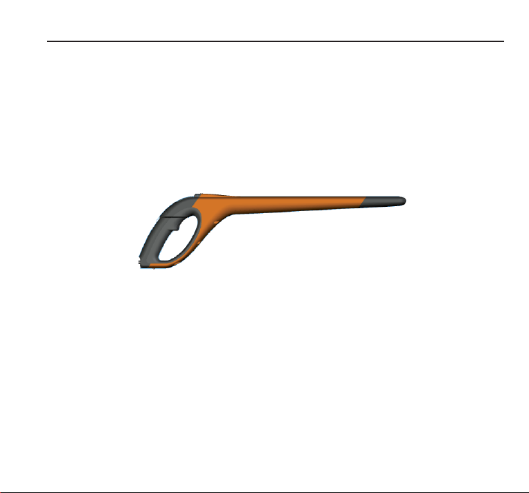
The Gallagher SmartReader HR3 is a Bluetooth enabled hand held Electronic ID reader
which allows the user to read and store ISO animal Electronic ID tags. The Gallagher
SmartReader HR3 contains internal memory and internal rechargeable batteries.
The Gallagher SmartReader HR
Memory Mode• - The captured Electronic ID tag data is stored in the SmartReader in
sessions until it is transferred to computer using the MyScale Pro software, and is
also immediately sent out the Serial port (via cable) to a Scale or data logging
device.
Non-Memory Mode• - The captured Electronic ID tag data is immediately sent out the
Serial port (via Bluetooth or cable) to a Scale or data logging device.
Tag types read
The Gallagher SmartReader HR3 enables you to read both HDX (Half Duplex) and FDX-B
(Full Duplex-B) Electronic ID tags.
Care and Maintenance
The SmartReader HR3 is a tough and reliable product designed for use in typical livestock
environments. However, proper care and maintenance can extend the SmartReader’s
life.
Listed below are guidelines for keeping the SmartReader in good condition.
For optimal battery life, Gallagher recommends that you store the SmartReader in a •
cool, dry area (15 to 25 ° Celsius) out of direct sunlight.
After use, clean the SmartReader with a damp cloth. Take care not to scratch the •
display.
3 has two modes of operation:
5
5

Recharge the batteries after use and before storing for extended periods.•
MyScale Pro
The MyScale Pro software enables you to transfer Electronic ID tag numbers stored in
the SmartReader HR3 memory to a computer.
With MyScale Pro you can perform the following functions:
Download sessions from the SmartReader.•
NOTE: Sessions on the SmartReader are automatically deleted off the reader after
downloading.
Change session fi le names.•
View and Edit sessions.•
Print sessions.•
For further details refer to the MyScale Pro for SmartReaders User Manual.
*
Configurator software
The Confi gurator is a software program provided with the SmartReader. It is used to
alter user settings on the SmartReader.
The Confi gurator is for advanced users and should be used with care as altering settings
affects the operation of the SmartReader.
The Confi gurator software is automatically installed with the MyScale Pro software or
can be installed separately.
For further details refer to the SmartReader HR
* How these documents are accessible to you depends on what option you selected
when installing MyScale Pro. Either:
double-click the shortcut on your desktop, or•
from the • Start menu, select All Programs > MyScale
Note: Adobe Acrobat is needed to be able to read these documents. If not already
installed on your PC, it is available on the installation CD (AdbeRdr810_en_US.exe).
3 Confi gurator User Manual. *
6

User information
Kit Contents
The Gallagher SmartReader HR3 box contains:
Gallagher SmartReader HR•
Reader to RS232 (weighscale comms/power) cable•
RS232 plug (power socket) to 12v battery cable•
Bluetooth RS232 adaptor with short extension cable•
USB to RS232 cable•
Instruction manual•
15 V DC battery charger (100-240 VAC)•
MyScale Pro CD•
Terminology
The following are terms and abbreviations used throughout this manual:
Bluetooth Bluetooth is a short-range radio communication technology. It
Bluetooth
module
Bluetooth to
RS232 device
enables data to be transmitted wirelessly over short distances.
Mounted in SmartReader handle. Sends Electronic ID tag data to the
Bluetooth device (RS232 or USB).
Connected to the Serial port of the Scale and receives the tag data
sent by the SmartReader.
Receives Bluetooth communications from the SmartReader and
converts the received information into RS232 format so it can be
passed onto a Scale.
The Bluetooth module in the SmartReader and the Bluetooth device
are paired.
3 (Bluetooth enabled)
7

Bluetooth to
USB device
Connected to the USB port of a computer and receives the tag data
sent by the SmartReader.
Receives the Bluetooth communications from the SmartReader and
passes the information onto a computer for deciphering.
(Note: This is not supplied, but is an optional extra.)
Tag Buffer A temporary storage area in memory for tag data.
Electronic ID
tag number
The Electronic ID tag number is the electronic code in an ear tag that
can be scanned to recognise an individual animal.
Antenna Contains the aerial used to capture Electronic ID tag data.
Activate the
SmartReader
Turn on the SmartReader ready for use. The screen turns on and
allows you to select various user options.
Double-Click Two quick successive clicks of the SmartReader trigger.
Memory
mode
The captured Electronic ID tag data is stored in the SmartReader in
sessions until it is transferred to computer using the MyScale Pro
software.
Non-memory
mode
The captured Electronic ID tag data is immediately sent out the Serial
port (via Bluetooth or cable) to a Scale or data logging device.
Read period The time the SmartReader is actively scanning for Electronic ID tags.
Once the read period ends the SmartReader antenna is turned off.
Default time is three seconds. This time can be altered. See the
SmartReader HR
3 Confi gurator User Manual.
Scale A digital weighing display unit that detaches from loadbars and
connects to your computer.
Scan for tags Turn on the SmartReader and single-click the trigger. This activates
the antenna and makes it ready to read Electronic ID tag data once
the tags move within the reader range.
Single-Click A single click of the SmartReader trigger.
8
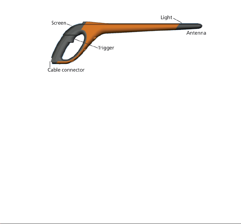
SmartReader HR3 features
Trigger
Use the trigger to activate the SmartReader, access the SmartReader menu and collect
tag data.
Single-Click• - A single click of the SmartReader trigger.
Double-Click• - Two quick successive clicks of the SmartReader trigger.
Beeper
The beeper sounds in the following situations:
on power up•
after a successful Electronic ID tag read•
when the trigger is pulled (single beep)•
on a duplicate tag read (two beeps). See • Duplicate Tags (p 24)
if maximum number of sessions reached (long single beep)•
The beeper can be turned on and off. See • SmartReader HR
Manual.
3 Confi gurator User
9

Vibrator
The handle will vibrate upon Electronic ID recognition. This is a single vibration period
whether the tag is duplicate or unique.
The vibrator can be turned on and off, see SmartReader HR
3 Confi gurator User Manual.
Bluetooth enabled
The SmartReader is Bluetooth enabled. This allows Electronic ID tag data to be
wirelessly transmitted to a paired Bluetooth enabled device (e.g. Scale or other data
logging devices). This is turned on or off depending on operating mode, which is
altered in the Confi gurator. See the SmartReader HR3 Confi gurator
User Manual.
Lamp
The lamp (red) illuminates for the
following reasons:
When the SmartReader scans for •
Electronic ID tags, the red lamp fl ashes
on and off.
On a successful tag read. The lamp •
remains solid for an extended period.
Note: If a tag is not read within the read period the lamp stops fl ashing.
The timing of the lamp illumination can be altered, see the SmartReader HR
Confi gurator User Manual.
3
10

Screen
Operating Mode
There are two operating modes on the SmartReader HR3:
Memory mode• - The captured Electronic ID tag data is stored in the SmartReader in
sessions until it is transferred to computer using the MyScale Pro software. See the
MyScale Pro for SmartReaders Use Manual, and the above graphic.
Non-Memory mode• - The captured Electronic ID tag data is immediately sent out the
Serial port (via Bluetooth or cable) to a Scale or data logging device.
Memory counter
Applicable when in Memory mode only - Displays OFF when in Non-memory mode.
The Memory counter indicates the total number of Electronic ID tags stored in the
SmartReader regardless of the number of sessions involved.
The SmartReader HR3 can store up to 5000 Electronic ID tags. When it reaches 5000, the
counter is replaced with the word “FULL”.
EID tag number
Displays the full 16 digit Electronic ID tag number of the last read tag.
The fi rst 4 digits identify the country code or the manufacturer. The last 12 digits
identify the individual animal.
11

Bluetooth symbol
If the bluetooth icon is visible on the SmartReader screen, the internal Bluetooth
module is communicating to another device (scale or computer).
Note: A visible Bluetooth symbol does not mean the Scale or data logging
device is ready to accept the transmitted data. See the appropriate
manufacturer’s documentation for further information.
Battery Icon
During operation, the Battery icon shows the level of charge in the internal battery, see
Battery icon status - Operation (p 16).
During charging, the Battery icon shows the stage of charging, see Battery icon status -
Charging (p 16).
Cable connector
A Data and power cable connects into the Cable connector.
This cable enables:
data to be transferred to a computer•
data to be transferred to scales•
the supplied • 15 V battery charger to charge the
internal battery on the SmartReader. See Charging
using the 15 V battery charger (p 14).
the • 12V battery cable to charge the internal battery
on the SmartReader. See Charging using a 12 V
battery (p 15).
The cable connector is a serial port. All tag data is
automatically sent out this port no matter which
operating mode is selected.
12

Antenna
Any Electronic ID tags that come within 27 cm of the
Antenna will be read. If there is more than one tag in
the range of the reader, neither tag will get read.
The reader may capture tags up to 33 centimetres (13”) away. Range settings are
variable. See the SmartReader HR
3 Confi gurator User Manual.
13

Power options
This section describes how to charge the internal battery in the SmartReader and how to
operate the SmartReader when the internal battery is fl at.
Note: The recommended ambient temperature limits for charging are 10° to 45° Celsius.
If the temperature of the reader goes above 45°, the word “TEMP” will replace the
battery icon on the screen and the reader will not charge.
Charging using the 15 V battery charger
To charge the SmartReader internal battery using the 15 V battery charger complete the
following steps:
Plug the 1. Data and power cable into the cable connector on the SmartReader.
Plug the 2. 15 V battery charger to the Data and power cable DB9 connector using the
2.5 mm Coaxial plug.
Plug the 3. 15 V battery charger into power socket and switch on.
Make sure the battery icon is showing that charging is occurring. See 4. Battery icon
status - Charging (p 16)
Note: While powered from the 15 V battery charger, Electronic ID tags cannot be read.
14

Charging using a 12 V battery
To charge the SmartReader internal battery using a 12 V battery, complete the following
steps:
Plug the 1. Data and power cable into the cable connector on the SmartReader.
Plug the 2. 12 V battery cable to the Data and power cable DB9 connector using the 2.5
mm Coaxial plug.
Connect the 3. 12 V battery cable to the 12 V battery.
Connect the Red lead to the positive terminal.
Connect the Black lead to the negative terminal.
Make sure the battery icon is showing that charging is occurring. See 4. Battery icon
status – Charging (p 16).
Note:
While charging using the 12 V battery cable, the reading of Electronic ID tags can
continue.
When the trigger is Pulled and the SmartReader is scanning for Electronic ID tags,
charging is temporarily stopped until a tag is read or until the read period ends.
15

Battery icon status - Operation
During operation, the battery icon on the SmartReader screen indicates the actual
amount of charge left in the battery.
Note: To show the correct value the SmartReader must be turned on and disconnected
from any external power supply.
Fully charged The battery icon displays as a solid black block.
Partial charged The battery icon displays a block that represents the
Almost fl at The battery icon fl ashes the icon outline indicating
Completely fl at The screen is blank until a charging cable is
amount of charge left in the internal battery pack.
that the SmartReader is about to shut down.
connected.
Battery icon status - Charging
When the SmartReader is connected to an external power supply (12 V battery or 15V
battery charger) the battery icon displays the charging status:
Charging Battery icon shows all the bars constantly fi lling and
Topping up Battery icon shows the fi rst three bars constantly full
Trickle charging Battery icon shows only one clear bar that is
Note: While charging using the 12 V battery cable, the reading of Electronic ID tags can
continue. When the trigger is pulled and the SmartReader is scanning for Electronic ID
tags, charging is temporarily stopped until a tag is read or until the read period ends.
While connected to the 15 V battery charger, Electronic ID tags can not be read.
16
then disappearing.
and the remainder fi lling and then disappearing.
constantly travelling the length of the full Icon.

Setting up the SmartReader HR3
Depending on how you intend using the SmartReader HR3 you may need to set one or
both the following options:
the SmartReader operating mode, see • Selecting an operating mode (p 18).
the connection to Scale, see • Connecting to the Scale (p 20).
Via Bluetooth (wireless)•
Via cable•
Note: You can also connect to a computer or other data logging device.
See “Connecting the SmartReader to the computer” in the SmartReader HR
Confi gurator User Manual.
Operating modes
The SmartReader has two operating modes:
Memory Mode:
The captured Electronic ID tag data is stored in the
SmartReader in sessions until it is transferred to computer
using the MyScale Pro software.
If you are in Memory mode the following screen displays:
Non-Memory Mode:
If you are in1. Non-memory mode the following screen
displays:
The captured Electronic ID tag data is immediately sent2.
out the Serial port (via Bluetooth or cable) to a Scale or
data logging device.
3
17

Selecting an operating mode
Activate the SmartReader (a Single-Click on the trigger).1.
The introduction screen displays briefl y:
A Bluetooth connection attempt is made:
If not required, a single trigger click will cancel this attempt.
A screen similar to the following displays:
18

Identify the current operating mode.2.
If in Memory
mode, the
screen displays:
Determine which operating mode you need to be in.3.
If you need to change the operating mode, double-click the SmartReader trigger to 4.
access the menu options.
If in Memory
mode, the
screen displays:
To select an option use the trigger and Single Click or Double-Click as required. If neither
option is selected within 20 seconds the menu clears and the main screen displays.
Note: Delay period is able to be altered with the Confi gurator.
If in Non-
memory mode,
the screen
displays:
If in Non-memory
mode, the screen
displays:
Memory mode options
New Session
Single-Click the trigger to close the current session and create a new session.
All Electronic ID tags read from that point on are saved into this new session.
The Memory counter is unaffected by this option.
See Memory Counter next.
19

Memory Counter
The Memory counter is only applicable when in Memory mode.
Once the memory is full, the Memory counter displays FULL. Note
however that even when the memory is full, if a new EID tag is read
the number of tag reads in the current session still increases (in the
example shown, 28 is the number of tag reads).
Note: Once the memory is full in Memory mode, each time you
read a new EID tag, by default, the oldest EID tag data is deleted
and the newest EID tag data is stored. This can be changed using the ‘Overwrite’ setting
in Confi gurator. For further details refer to the SmartReader HR
3 Confi gurator User
Manual.
The Memory counter is returned to 0 by downloading tag data using MyScale Pro. For
further details refer to the MyScale Pro for SmartReaders User Manual.
Session Limit
The SmartReader has a session limit of 100. While the current
session number cannot be identifi ed, if you reach the session limit
the following screen displays:
If this occurs, you should immediately download the sessions using
MyScale Pro. However, you can continue to read and store tags to
the current session, providing there is suffi cient space within the
current session, or it has been confi gured to allow this. Refer to
the SmartReader HR
3 Confi gurator User Manual.
Non-Memory mode options
Zero count
Single-Click the trigger to reset the number of tags read in the current session. Only
applicable when in Non-memory mode.
20

Connecting to the Scale
When operating in Non-memory mode, you need to setup how the read Electronic ID tag
data is to be transferred to a Scale.
There are two methods:
Bluetooth (wireless), see • Bluetooth to Scale. (p 21)
Data and power cable, see • Data cable to Scale (p 22).
Once you have set up the connection you need to test the connection, see Testing the
connection between Scale and SmartReader (p 23).
Note: You can also connect to a computer or other data logging device. See
“Connecting the SmartReader to the computer” in the SmartReader HR
User Manual.
Setting up the Scale
Consult the User Manual supplied with your scale. It is likely you will have to set the
time and date and assign a communications port (the SmartReader connects to COM 2
on the Gallagher Scale).
Bluetooth to Scale
Using the short Serial cable, plug the supplied Bluetooth to 1.
RS232 adaptor into the Scale (On a Gallagher Scale connect
to Port 2).
Consult the scale User Manual to turn on the Scale and set it
up to receive the Electronic ID tag data.
Note: Check that the switch on the side of the adaptor is set
to the furthest position, (i.e. ‘PoRI’ on some adaptors), from
the DB9 adaptor.
Activate the SmartReader or access the Bluetooth connection 2.
screen via the Click Trigger menu. The SmartReader screen
activates and the following screen displays:
3 Confi gurator
21

The Bluetooth icon displays on the SmartReader main screen if connection
is made between the SmartReader and the Bluetooth to RS232 adaptor, or
Bluetooth to USB adaptor.
Test the connection between the Scale and the SmartReader, see 3. Testing
the connection between Scale and SmartReader (p 23).
Note: If you are connecting to a computer or other data logging device you need to
have software running (not supplied) to collect the Electronic ID tag data.
Data and power cable to Scale
Plug the 1. Data and power cable into the cable connector on the SmartReader.
Plug the 2. Data and power cable DB9 into the Scale.
On a Gallagher Scale connect to Port 2.
Turn on the Gallagher Scale.3.
Set up the Gallagher Scale to receive the Electronic ID tag data. See 4. Setting up the
Scale (p 21).
Note: If you are connecting to a computer or other data logging device you need to
have software running (not supplied) to collect the Electronic ID tag data.
22

Test the connection between the Scale and the SmartReader, see 5. Testing the
connection between Scale and SmartReader (p 23).
Pairing the RS232 Adaptor with your SmartReader
The process of pairing the RS232 Adaptor with the SmartReader is carried out by your
Gallagher distributor. If you are receiving the Bluetooth adaptor with your SmartReader,
the pairing will already be in effect. If you are having diffi culties, take your SmartReader
and your adaptor to your nearest distributor for pairing.
Testing the connection between Scale and SmartReader
Once the connection between the SmartReader and Scale is established you need to test
the Scale is receiving the Electronic ID tag data from the SmartReader.
Activate the SmartReader.1.
Scan an Electronic ID tag.2.
Did the Electronic ID tag number display on the Scale?3.
If • yes, the connection is working.
If • no, the connection is not working.
Check the following:
• that you have set up the Scale communications port.
• that the Bluetooth connection icon is visible on the SmartReader.
• the Bluetooth light is visible on the Bluetooth adapter.
• that the Scale is set up correctly (refer to the MyScale Pro for SmartReaders
User Manual).
23

Using the SmartReader
Once you have set up the SmartReader you are ready to use it to capture Electronic ID
tag data.
For details on how to set up the SmartReader, see Setting up the SmartReader (p 17).
Single-Click the trigger to activate the SmartReader.1.
Single-Click the trigger to scan for Electronic ID tags.2.
Move the tip of the SmartReader towards the Electronic ID tag on the animal.3.
Once an Electronic ID tag is read the SmartReader beeps and the lamp illuminates
for an extended period.
Repeat from step 2 until all animals Electronic ID tags are read.4.
Notes:
The SmartReader beeps twice if a duplicate tag is read.•
The SmartReader stops scanning for Electronic ID tags once a tag is read. You need •
to Single-Click the trigger to scan for the next Electronic ID tag.
If an Electronic ID tag is not read within the read period the SmartReader stops •
scanning for tags.
If the SmartReader is not used for a period it may timeout to conserve battery •
power. Reactivate with a single trigger click.
Duplicate tags
Duplicate tags are placed in a temporary storage area referred to as a buffer. The
tag buffer can store data for up to 50 tags. A tag will only be retained for a defi ned
period of time (the SmartReader must be activated for this time to decrement). These
settings are able to be altered with the Confi gurator. For further details refer to the
SmartReader HR3 Confi gurator User Manual.
The tag buffer is emptied each time a new session is created, or the session count is reset
to zero.
24

Accessories
USB Bluetooth Adaptor
Gallagher is able to supply an adapter (part number G03202) that uses a USB port to
enable your computer to make wireless communication with your SmartReader.
The wireless connection can be used to download sessions or to connect to the
Confi gurator.
Many modern computers are manufactured “Bluetooth enabled” and this accessory is
not required for those models.
Specifications
Waste Electrical and Electronic Equipment
This symbol on the product or its packaging indicates that this product
must not be disposed of with other waste. Instead, it is your responsibility
to dispose of your waste equipment by handing it over to a designated
collection point for the recycling of waste electrical and electronic
equipment. The separate collection and recycling of your waste equipment
at the time of disposal will help conserve natural resources and ensure that
it is recycled in a manner that protects human health and the environment.
For more information about where you can drop off your waste equipment
for recycling, please contact your local city recycling offi ce or the dealer from
whom you purchased the product.
25

Approvals and Standards
FCC
This device complies with Part 15 of the FCC Rules. Operation is subject to the following
two conditions: (1) this device may not cause harmful interference, and (2) this device
must accept any interference received, including interference that may cause undesired
operation.
This equipment has been tested and found to comply with the limits for a Class B digital
device, pursuant to part 15 of the FCC Rules. These limits are designed to provide
reasonable protection against harmful interference in a residential installation. This
equipment generates, uses and can radiate radio frequency energy and, if not installed
and used in accordance with the instructions, may cause harmful interference to radio
communications. However, there is no guarantee that interference will not occur in a
particular installation.
If this equipment does cause harmful interference to radio or television reception, which
can be determined by turning the equipment off and on, the user is encouraged to try to
correct the interference by one or more of the following measures:
Reorient or relocate the receiving antenna.•
Increase the separation between the equipment and receiver.•
Connect the equipment into an outlet on a circuit different from that to which the •
receiver is connected.
Consult the dealer or an experienced radio/TV technician for help.•
CAUTION
Changes or modifi cations not expressly approved by Gallagher Group Limited could void
the user’s authority to operate the equipment.
Industry
Canada
26 26
The carrier frequency is 134.2 kHz, the RF output power is 75 dBµV/m @ 10 m.
This Category II radiocommunication device complies with Industry Canada Standard
RSS-310.
Ce dispositif de radiocommunication de catégorie II respecte la norme CNR-310
d’Industrie Canada.
Operation is subject to the following two conditions: (1) this device may not cause
interference, and (2) this device must accept any interference, including interference that
may cause undesired operation of the device.


TWO YEAR WARRANTY
FOR THIS PRODUCT FROM DATE OF PURCHASE
MODEL
.........................................................................
SERIAL NO
.........................................................................
DATE PURCHASED
.........................................................................
This product is guaranteed free from defects in
material or workmanship for a period of two
years from date of purchase by the end user. Gallagher will repair or replace at their option any
faulty product returned to them or their Dealer
within this time period. Freight/forwarding costs
incurred by the Customer in the warranty process
remain the responsibility of the Customer.
This warranty does not cover damage (including
subsequent corrosive damage) due to:
Unauthorised repairs •
Modifi cations•
PLEASE READ INSTRUCTIONS CAREFULLY BEFORE USE.
PLEASE COMPLETE DETAILS AND KEEP WITH YOUR RECEIPT — IT IS YOUR
PROOF OF WARRANTY
Failure to follow care and maintenance •
guidelines described in the User Manual
Physical Mishandling •
Lightning Strike•
Floods, fi res or acts of God•
Use of an arc welder on loadbars or •
equipment or steelwork attached to loadbars
while a WeighScale is connected
Gallagher, their Distributors, and their Dealers
accept no responsibility for the misuse of this
product.
Gallagher, their Distributors, and their Dealers
accept no responsibility for any accident caused
subsequently to any tampering with or modifi cation to or misuse of this product.
Gallagher, their Distributors, and their Dealers
accept no liability for consequences and/or secondary damages or losses of any kind sustained
directly or indirectly, a result of failure or defect
in any product, material, installation or service.
 Loading...