

Gallagher
T21 PIV Reader
Installaon Note
T21 PIV Reader Black: C305500
T21 PIV Reader White: C305501
T21 PIV Reader - Mul Tech Black: C305510
T21 PIV Reader - Mul Tech White: C305511
3E4234 Gallagher T21 PIV Reader | Edion 1 | August 2016
Copyright © Gallagher Group Limited
Page 1

Disclaimer
This document gives certain informaon about products and/or services provided by Gallagher Group Limited
or its related companies (referred to as "Gallagher Group").
The informaon is indicave only and is subject to change without noce meaning it may be out of date at any
given me. Although every commercially reasonable eort has been taken to ensure the quality and accuracy
of the informaon, Gallagher Group makes no representaon as to its accuracy or completeness and it should
not be relied on as such. To the extent permied by law, all express or implied, or other representaons or
warranes in relaon to the informaon are expressly excluded.
Neither Gallagher Group nor any of its directors, employees or other representaves shall be responsible
for any loss that you may incur, either directly or indirectly, arising from any use or decisions based on the
informaon provided.
Except where stated otherwise, the informaon is subject to copyright owned by Gallagher Group and you may
not sell it without permission. Gallagher Group is the owner of all trademarks reproduced in this informaon.
All trademarks which are not the property of Gallagher Group, are acknowledged.
Copyright © Gallagher Group Ltd 2016. All rights reserved.
3E4234 Gallagher T21 PIV Reader | Edion 1 | August 2016
Copyright © Gallagher Group Limited
Page 2

Contents
1 Introducon ..................................................................................................................................... 4
2 Before you begin .............................................................................................................................. 5
3 Distance between readers ............................................................................................................... 7
4 Installaon ....................................................................................................................................... 8
5 Screen brightness ........................................................................................................................... 11
6 Informaon screen ......................................................................................................................... 12
7 LED indicaons ............................................................................................................................... 12
8 Accessories .................................................................................................................................... 12
9 Icons ............................................................................................................................................... 13
10 Technical specicaons ..................................................................................................................14
11 Approvals and standards ................................................................................................................ 15
12 Mounng dimensions .................................................................................................................... 16
3E4234 Gallagher T21 PIV Reader | Edion 1 | August 2016
Copyright © Gallagher Group Limited
Page 3
1 Introducon
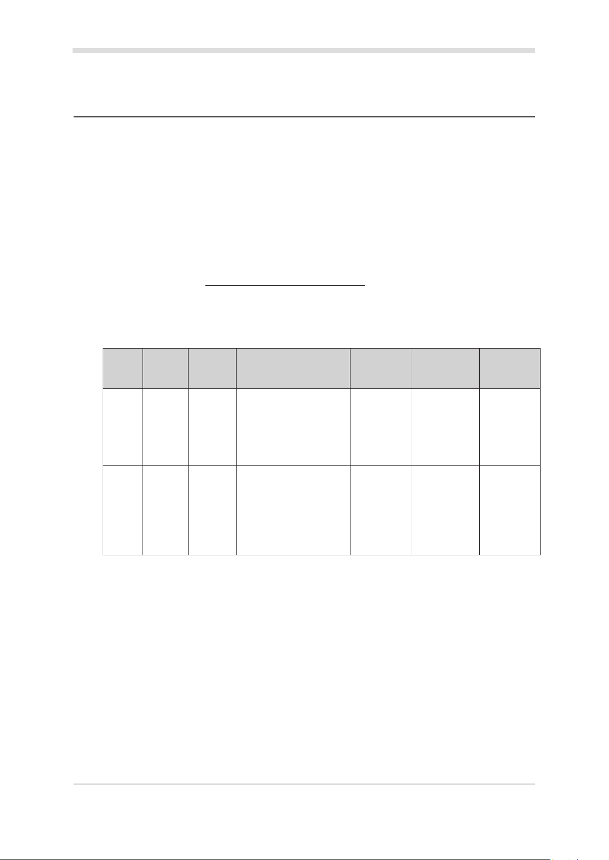
The Gallagher T21 PIV Reader is available in four variants. The variant you have purchased determines
the supported card technologies for the reader, refer to the topic "Reader variants feature summary"
below. The reader's contact slot reads PIV card data, for PIV PIN validaon.
The reader is compable with the Gallagher Command Centre soware vEL7.50 (or later). The reader
connects to a Gallagher Controller 6000 High Spec PIV (C305101). The reader sends informaon to the
Controller and acts upon informaon sent from the Controller. The reader itself does not make any
access decisions
The reader can be mounted on a rectangular 50 mm x 75 mm (2 in x 3 in) ush box, a BS 4662 Brish
Standard square ush box, or any solid at surface.
For instrucons on how to use this product, refer to the "3E3685 User Guide T2x Terminal" which can be
downloaded from here: hps://security-support.gallagher.com
Reader variants feature summary
The available funconality and supported card technologies for each variant are shown below.
Reader
Variant
T21 PIV
Reader
Product
Codes
C305500
C305501
Cardax IV HBUSFunconality HBUS
Supported
From
None Access Control
Alarms Management
vHT4.2//b48
(vEL7.50)
Fence Zone Management
Cards
Supported
PIV, PIV-I, CAC,
TWIC, Mifare
DESFire EV1,
Bluetooth®
Supported
From
None
Mifare Plus
and Mifare
Classic cards
T21 PIV
Reader
Mul
Tech
C305510
C305511
None Access Control
Alarms Management
Fence Zone Management
vHT4.2//b48
(vEL7.50)
PIV, PIV-I, CAC,
TWIC, Mifare
DESFire EV1,
Mifare Plus,
vHT4.2//b48
(vEL7.60)
Mifare Classic
and 125 KHz
cards
The following is not supported by the T21 PIV Reader:
• PIV PIN to PACS
• PIN is User Code (for PIV card access)
• Duress (for PIV card access)
Note: To view the vHT soware version used by the reader, press and hold the '#' key for 3 seconds.
3E4234 Gallagher T21 PIV Reader | Edion 1 | August 2016
Copyright © Gallagher Group Limited
Page 4

2 Before you begin
2.1 Shipment contents
Check the shipment contains the following items:
• 1 x Gallagher T21 PIV Reader facia assembly
• 1 x Gallagher T21 PIV Reader bezel
• 2 x 6-32 UNC (32 mm) Phillips drive xing screws
• 2 x M3.5 (40 mm) Phillips drive xing screws
• 5 x 25 mm No.6 self tapping, pan head, Phillips drive xing screws
• 5 x 40 mm No.6 self tapping, pan head, Phillips drive xing screws
• 1 x M3 Torx Post (T10) Security screw
2.2 Power supply
The Gallagher T21 PIV Reader is designed to operate over a supply voltage range of 9 - 16 Vdc
measured at the readers terminals. The operang current draw is dependent on the supply
voltage at the reader.
The power source should be linear or a good quality switched-mode power supply.
The performance of the reader may be aected by a low quality, noisy power supply.
2.3 Cabling
The Gallagher T21 PIV Reader requires a minimum cable size of 4 core 24 AWG (0.2 mm2)
stranded security cable. This cable allows the transmission of data (2 wires) and power (2 wires).
When using a single cable to carry both power supply and data, both the power supply voltage
drop and data requirements must be considered. Although the reader is specied to operate at
9 Vdc, for good engineering design it is recommended that the voltage at the reader should be
approximately 12 Vdc.
HBUS cabling topology
The HBUS communicaons protocol is based on the RS485 standard and allows the reader to
communicate over a distance of up to 500 m (1640 ).
The cabling between HBUS devices should be done in a "daisy chain" topology, (i.e. A "T" or
"Star" topology should not be used between devices). Should "Star" or "Home-Run" wiring be
required, the HBUS 4H/8H Modules and the HBUS Door Module allow mulple HBUS devices to
be individually wired to the one physical locaon.
The end devices on the HBUS cable should be terminated using 120 ohms resistance. To
terminate the Controller, connect the supplied on-board terminaon jumpers to the Controller.
To terminate the Gallagher T21 PIV Reader, connect the orange (terminaon) wire to the green
(HBUS A) wire. Terminaon is already included at the HBUS Module, (i.e. each HBUS port is
permanently terminated at the module).
3E4234 Gallagher T21 PIV Reader | Edion 1 | August 2016
Copyright © Gallagher Group Limited
Page 5
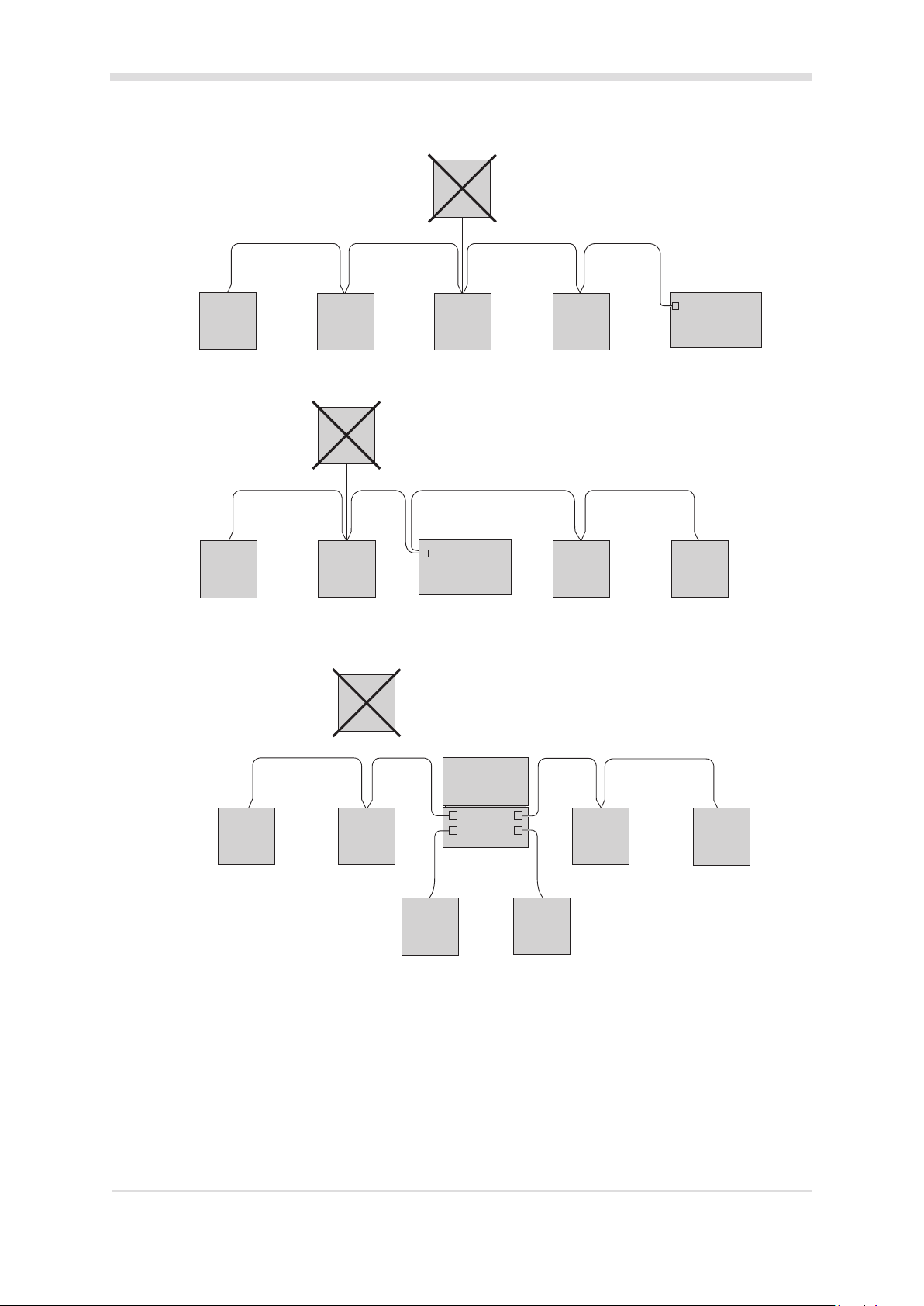
HBUS
Device
"T" or "Star" circuits are
not permied between
HBUS devices
HBUS
Device
Terminate
HBUS
Device
Terminate
HBUS
Device
HBUS
Device
HBUS
Device
Device
"T" or "Star" circuits are
not permied between
HBUS devices
Remove the on-board
terminaon jumper
HBUS
"T" or "Star" circuits are
not permied between
HBUS
Device
RS485 1
Controller 6000
HBUS devices
HBUS
Device
HBUS
Device
RS485 1
Controller 6000
Connect the on-board
terminaon jumper
HBUS
Device
Terminate
HBUS
Device
HBUS
Device
Terminate
3E4234 Gallagher T21 PIV Reader | Edion 1 | August 2016
Copyright © Gallagher Group Limited
HBUS
Device
Terminate
Controller 6000
H4
H1
H8
H5
HBUS Module
HBUS
Device
Terminate
HBUS
Device
HBUS
Device
Terminate
Page 6
Cable distance
Cable type Cable format* Single reader
connected using
HBUS data only in a
single cable
CAT 5e or beer** 4 twisted pair
Each 2 x 0.2 mm
BELDEN 9842**
(shielded)
SEC472 4 x 0.2 mm
2 twisted pair
Each 2 x 0.2 mm
2
2
(24 AWG)
2
(24 AWG)
500 m (1640 ) 50 m (165 )
500 m (1640 ) 50 m (165 )
400 m (1310 ) 50 m (165 )
Single reader
connected using
power and data in a
single cable
Not twisted pairs (24 AWG)
SEC4142 4 x 0.4 mm
2
400 m (1310 ) 100 m (330 )
Not twisted pairs (21 AWG)
* The matching of wire sizes to equivalent wire gauges are only approximate.
** Recommended cable types for opmal HBUS RS485 performance.
Notes:
• Shielded cable may reduce the obtainable cable length. Shielded cable should be
grounded at the Controller end only.
• If other cable types are used, operang distances and performance may be reduced
depending on the cable quality.
• The recommendaon for opmal performance is up to 20 x T21 PIV Readers can be
connected to one Controller. Of these 20 readers, up to 4 could be congured for alarm
zone (or fence controller) management.
A reader is congured for alarm zone management when it has either Alarm Zones
congured on the Alarm Zones properes page or items congured upon its mimic panel.
3 Distance between readers
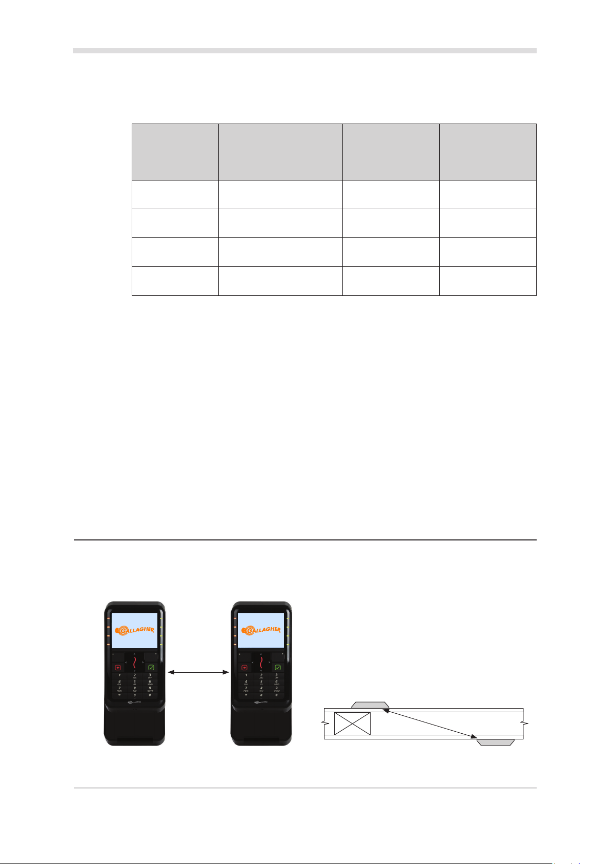
The distance separang any two proximity readers must not be less than 200 mm (8 in) in all direcons.
When mounng a proximity reader on an internal wall, check that any reader xed to the other side of
the wall is not less than 200 mm (8 in) away.
200 mm
200 mm
3E4234 Gallagher T21 PIV Reader | Edion 1 | August 2016
Copyright © Gallagher Group Limited
Page 7
4 Installaon
ATTENTION: This equipment contains components that can be damaged by
electrostac discharge. Ensure both you and the equipment are earthed before
beginning any servicing.
The Gallagher T21 PIV Reader can be mounted on:
• a vercal, rectangular 50 mm x 75 mm (2 in x 3 in) ush box
• a BS 4662 Brish Standard square ush box
• any solid at surface
The recommended mounng height for the reader is 1.1 m (3.6 ) from the oor level to the centre
of the reader. However this may vary in some countries and you should check local regulaons for
variaons to this height.
Notes:
• Consideraon should be given to the installaon environment when using Gallagher mobile
credenals, as the Bluetooth® wireless technology read range may be reduced.
• Installaon on metal surfaces, parcularly those with a large surface area will reduce read range.
The extent to which the range is reduced will depend upon the type of metal surface.
• When mounng on a ush box, the corner screws must be used as well as the ush box screws.
Without corner screws the top of the product is vulnerable to separaon from the wall.
1. Ensure the building cable has been run out through the ush box.
If you are not mounng to a ush box, use the reader bezel as a guide, to drill all ve holes. Drill
the 13 mm (1/2 inch) diameter centre hole (this is the centre hole for which the building cable
will exit the mounng surface) and the four corner xing holes. Ensure the centre hole allows
the cable to run freely out through the mounng surface, so that the reader facia can clip into
the bezel.
Note: There is no room for the building cable to be squeezed into the reader bezel. The building
cable must remain within the ush box or wall cavity.
2. Run the building cable through the reader bezel.
3. Secure the bezel to the ush box using the two screws provided.
When securing the bezel to a vercal, rectangular ush box, use the 6-32 UNC screws provided.
When securing the bezel to a BS 4662 Brish Standard square ush box, use the M3.5 screws
provided.
3E4234 Gallagher T21 PIV Reader | Edion 1 | August 2016
Copyright © Gallagher Group Limited
Page 8
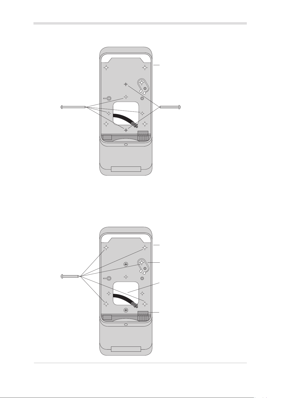
Bezel
M3.5 (40 mm) screw
6-32 (32 mm) screw
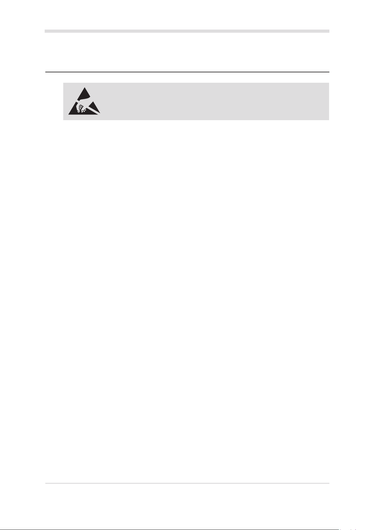
4. Drill pilot holes for the four corner xing holes and the tamper tab. Secure the bezel to the
mounng surface using the four corner xing screws provided. Secure the tamper tab (located
in the bezel) to the mounng surface using the remaining xing screw provided. It is important
the four corner xing screws are used to ensure the reader is ush with and ght against the
mounng surface.
Note: It is strongly recommended that you use the screws provided. If an alternave screw is
used, the head must be no larger nor deeper than that of the screw provided.
No. 6 pan
head screw
3E4234 Gallagher T21 PIV Reader | Edion 1 | August 2016
Copyright © Gallagher Group Limited
Bezel
Tamper tab
Building cable
Connect building
cable to terminal
block
Page 9

5. The reader connects to a Gallagher Controller 6000 High Spec PIV, a Gallagher 4H/8H HBUS
Module (aached to the Controller 6000 High Spec PIV), or a Gallagher HBUS Door Module
(connected to a Controller 6000 High Spec PIV).
Unplug the reader's terminal block from the PCB. Connect the wires from the building cable to
the terminal block as shown. Plug the terminal block back into the PCB.
HBUS connecon: HBUS connecon terminated:
HBUS A Green
HBUS B Brown
Negave Black
Posive Red
Building Cable
+ - B A T
HBUS A Green
HBUS B Brown
Negave Black
Posive Red
Building Cable
+ - B A T
If the reader is the end device on the HBUS cable, terminate the reader by connecng a short
piece of wire between terminals T and A.
6. Secure the reader cable using the cable retenon peg, as shown in the following diagram.
Plug the reader cable into the connector.
Rear of facia
Reader cable retenon peg
7. Fit the facia assembly into the bezel by clipping the small lip, into the top of the bezel and holding
the top, press the boom of the facia assembly down into the bezel.
8. Insert the M3 Torx Post Security screw (using a T10 Torx Post Security screwdriver) through the
hole below the reader facia.
Note: The Torx Post Security screw needs only to be lightly ghtened.
3E4234 Gallagher T21 PIV Reader | Edion 1 | August 2016
Copyright © Gallagher Group Limited
Page 10

Fit security screw to
secure facia to bezel
9. Removal of the facia assembly is a simple reversal of these steps.
Hint: Aer removal of the security screw, press the top of the facia. The boom of the facia will
exit the reader bezel. Alternavely, carefully use an electrical screwdriver to lever the boom of
the facia away from the bezel.
10. Congure the reader in Command Centre. Refer to the topic "Conguring an HBUS Contact Card
Reader" in the Command Centre Conguraon Client Online Help.
11. The reader's contact card slot is rated for 100,000 card inserons. Should the reader's contact
card slot become blocked or wear over me, a replacement bezel including the contact card
reader (C305280 or C305281) can be purchased.
5 Screen brightness
When the reader is in use the screen brightness will be set to full. If the reader hasn't been used for 30
seconds, the screen brightness is dimmed. If the reader hasn't been used for 30 minutes, the screen is
turned o.
Note: The reader screen can be set to on at all mes ('Always on' seng enabled on the HBUS Contact
Card Reader item's property page in Command Centre). If this seng is enabled, the reader's screen
will not turn o aer 30 minutes, but will dim aer 30 seconds of inacvity.
3E4234 Gallagher T21 PIV Reader | Edion 1 | August 2016
Copyright © Gallagher Group Limited
Page 11

6 Informaonscreen
To display the supported card technologies and the soware version numbers of the reader, press and
hold the '#' key for 3 seconds. The Informaon screen is displayed.
7 LEDindicaons
LED (squiggle) HBUSindicaon
3 Flash (Amber) No communicaons with the Controller.
The terminal screen displays the text 'Connecng...'.
2 Flash (Amber) Communicaons with the Controller, but terminal is not congured. The
terminal screen displays the text 'Not congured'.
1 Flash (Amber) Congured to a Controller, but terminal is not assigned to a door or elevator
car. Congured to a Controller but the Alarms Terminal has no Alarm Zone(s)
assigned to the Alarms Zones property page.
The terminal screen displays the text 'Not congured'.
On (Green or Red) Fully congured and funconing normally.
If assigned to a door or elevator car:
Green = Access mode is Free
Red = Access mode is Secure
Flashes Green Access has been granted.
Flashes Red Access has been denied.
Flashing Blue Reading and validang a PIV card. Reading a Gallagher mobile credenal.
8 Accessories
Accessory Product Code
T21 Bezel, Black C305280
T21 Bezel, White C305281
For the Alarms Terminal the LED is green when a user is logged on and red
when logged o.
3E4234 Gallagher T21 PIV Reader | Edion 1 | August 2016
Copyright © Gallagher Group Limited
Page 12

9 Icons
Insert Card Remove Card
Present Card
Present Two Cards
Access Granted Access Denied
Not Allowed
Card or Code
Armed
Enter PIN/Code
Free Access
3E4234 Gallagher T21 PIV Reader | Edion 1 | August 2016
Copyright © Gallagher Group Limited
Page 13

10 Technicalspecicaons
Roune maintenance: Not applicable for this reader.
Cleaning: This reader should be cleaned with mild soapy
water only. Do not use solvents or abrasives.
Voltage: 9 Vdc - 16 Vdc
Current: Inacve
1
T21 PIV Reader (at 9 Vdc): ??? mA ??? mA
T21 PIV Reader (at 13.6 Vdc): ??? mA ??? mA
T21 PIV Reader - Mul Tech (at 9 Vdc): ??? mA ??? mA
T21 PIV Reader - Mul Tech (at 13.6 Vdc): ??? mA ??? mA
Temperature range: -30 °C to +70 °C (-22 °F to +158 °F)
Note: Direct sunlight may increase the internal
reader temperature above the ambient
temperature level.
Humidity: 95% non condensing
4
Environmental protecon: IP33 (independently veried)
Impact rang: IK08 (independently veried)
Unit dimensions: Height 231.9 mm (9.1 in)
Width 95.8 mm (3.8 in)
Depth 33 mm (1.3 in)
Maximum number of readers on one HBUS cable: 20
Maximum number of alarms management
readers
3
on one Controller:
4
Maximum number of readers on one Controller: 20
1
The reader is idle. The screen is on (dimmed).
2
The screen is at maximum brightness.
3
A reader is congured for alarm zone management/fence controller management when it has either
Alarm Zones congured on the Alarm Zones properes page or items congured upon its mimic panel.
4
Gallagher T Series readers are UL humidity tested and cered to 85% and have been independently
veried to 95%.
Acve
2
Note: The current values stated above have been reported using the default conguraon of an HBUS
Contact Card Reader in Command Centre. Changing the conguraon may vary the current value.
3E4234 Gallagher T21 PIV Reader | Edion 1 | August 2016
Copyright © Gallagher Group Limited
Page 14

11 Approvals and standards
This symbol on the product or its packaging indicates that this product must not be disposed
of with other waste. Instead, it is your responsibility to dispose of your waste equipment by
handing it over to a designated collecon point for the recycling of waste electrical and electronic
equipment. The separate collecon and recycling of your waste equipment at the me of disposal
will help conserve natural resources and ensure that it is recycled in a manner that protects human
health and the environment. For more informaon about where you can drop o your waste
equipment for recycling, please contact your local city recycling oce or the dealer from whom
you purchased the product.
FCC
Industry
Canada
This device complies with part 15 of the FCC Rules. Operaon is subject to the following two
condions: (1) This device may not cause harmful interference, and (2) this device must accept any
interference received, including interference that may cause undesired operaon.
Note: Changes or modicaons not expressly approved by Gallagher Limited could void the user's
authority to operate this equipment.
Note: This equipment has been tested and found to comply with the limits for a Class B digital
device, pursuant to part 15 of the FCC Rules. These limits are designed to provide reasonable
protecon against harmful interference in a residenal installaon. This equipment generates,
uses and can radiate radio frequency energy and, if not installed and used in accordance with
the instrucons, may cause harmful interference to radio communicaons. However, there is no
guarantee that interference will not occur in a parcular installaon. If this equipment does cause
harmful interference to radio or television recepon, which can be determined by turning the
equipment o and on, the user is encouraged to try to correct the interference by one or more of
the following measures:
• Reorient or relocate the receiving antenna.
• Increase the separaon between the equipment and receiver.
• Connect the equipment into an outlet on a circuit dierent from that to which the receiver is
connected.
• Consult the dealer or an experienced radio/TV technician for help.
This device complies with Industry Canada licence-exempt RSS standard(s). Operaon is subject to
the following two condions: (1) this device may not cause interference, and (2) this device must
accept any interference, including interference that may cause undesired operaon of the device.
Industrie
Canada
Please refer to the document “3E2793 Gallagher Command Centre UL Conguraon Requirements” for a guide
to conguring the Gallagher system to the appropriate UL Standard.
3E4234 Gallagher T21 PIV Reader | Edion 1 | August 2016
Copyright © Gallagher Group Limited
Le présent appareil est conforme aux CNR d'Industrie Canada applicables aux appareils radio
exempts de licence. L'exploitaon est autorisée aux deux condions suivantes : (1) l'appareil
ne doit pas produire de brouillage, et (2) l'ulisateur de l'appareil doit accepter tout brouillage
radioélectrique subi, même si le brouillage est suscepble d'en compromere le fonconnement.
ETSI EN 300 330-2 V1.5.1:2011
EN50130-4:2011
Page 15

12 Mounngdimensions
95.8 mm (3.8 in)
70 mm (2.8 in)
29 mm (1.1 in)
45 mm (1.8 in)
102 mm (4 in)
83.3 mm (3.3 in)
231.9 mm (9.1 in)
60.3 mm (2.4 in)
20 mm
(0.8 in)
40 mm (1.6 in)
Cable exit within
1.8 x 1.6 inch hole
(45 x 40 mm)
60.3 mm (2.4 in)
IMPORTANT
This picture is not to scale, therefore use the measurements provided.
3E4234 Gallagher T21 PIV Reader | Edion 1 | August 2016
Copyright © Gallagher Group Limited
Page 16

Open Source Software License Notice
This product includes software code developed by third parties, including software code subject to the
GNU General Public License (“GPL”), the GNU Library General Public License (“LGPL”), and a
variety of additional licenses, including BSD-style licenses. As applicable, the terms of these licenses,
and information on obtaining access to the open source code used in this product, are available for
free download from https://security.gallagher.com/oss.
The open source code used in this product is distributed WITHOUT ANY WARRANTY and is subject
to the copyrights of one or more authors.
Please refer to the following license details for more information.
Open Source Software Licenses
GNU GENERAL PUBLIC LICENSE
Copyright (C) 1989, 1991 Free Software Foundation, Inc. 675 Mass Ave, Cambridge, MA 02139, USA
Everyone is permitted to copy and distribute verbatim copies of this license document, but changing it is not allowed.
Preamble
The licenses for most software are designed to take away your freedom to share and change it. By contrast, the GNU General Public License is intended to guarantee
your freedom to share and change free software--to make sure the software is free for all it s users. This General Public License applies to most of the Free Software
Foundation's software and to any other program whose authors commit to using it. (Some other Free Software Foundation software is covered by the GNU Library
General Public License instead.) You can apply it to your programs, too.
When we speak of free software, we are referring to freedom, not price. Our General Public Licenses are designed to make sure that you have the freedom to distribute
copies of free software (and charge for this service if you wish), that you receive source code or can get it if you want it, that you can change the software or use pieces of
it in new free programs; and that you know you can do these things.
To protect your rights, we need to make restrictions that forbid anyone to deny you these rights or to ask you to surrender the rights. These restrictions translate to certain
responsibilities for you if you distribute copies of the software, or if you modify it.
For example, if you distribute copies of such a program, whether gratis or for a fee, you must give the recipients all the rights that you have. You must make sure that
they, too, receive or can get the source code. And you must show them these terms so they know their rights.
We protect your rights with two steps: (1) copyright the software, and (2) offer you this license which gives you legal permission to copy, distribute and/or modify the
software.
Also, for each author's protection and ours, we want to make certain that everyone understands that there is no warranty for this free software. If the software is modified
by someone else and passed on, we want its recipients to know that what they have is not the original, so that any problems introduced by others will not reflect on the
original authors' reputations.
Finally, any free program is threatened constantly by software patents. We wish to avoid the danger that redistributors of a free program will individually obtain patent
licenses, in effect making the program proprietary. To prevent this, we have made it clear that any patent must be licensed for everyone's free use or not licensed at all.
The precise terms and conditions for copying, distribution and modification follow.
GNU GENERAL PUBLIC LICENSE
TERMS AND CONDITIONS FOR COPYING, DISTRIBUTION AND MODIFICATION
0. This License applies to any program or other work which contains a notice placed by the copyright holder saying it may be distributed under the terms of this General
Public License. The "Program", below, refers to any such program or work, and a "work based on the Program" means either the Program or any derivative work under
copyright law: that is to say, a work containing the Program or a portion of it, either verbatim or with modifications and/or translated into another language. (Hereinafter,
translation is included without limitation in the term "modification".) Each licensee is addressed as "you".
Activities other than copying, distribution and modification are not covered by this License; they are outside its scope. The act of running the Program is not restricted,
and the output from the Program is covered only if its contents constitute a work based on the Program (independent of having been made by running the Program).
Whether that is true depends on what the Program does.
1. You may copy and distribute verbatim copies of the Program's source code as you receive it, in any medium, provided that you conspicuously and appropriately publish
on each copy an appropriate copyright notice and disclaimer of warranty; keep intact all the notices that refer to this License and to the absence of any warranty; and give
any other recipients of the Program a copy of this License along with the Program.
You may charge a fee for the physical act of transferring a copy, and you may at your option offer warranty protection in exchange for a fee.
2. You may modify your copy or copies of the Program or any portion of it, thus forming a work based on the Program, and copy and distribute such modifications or work
under the terms of Section 1 above, provided that you also meet all of these conditions:
a) You must cause the modified files to carry prominent notices stating that you changed the files and the date of any change.
b) You must cause any work that you distribute or publish, that in whole or in part contains or is derived from the Program or any part thereof, to be licensed as a whole at
no charge to all third parties under the terms of this License.
c) If the modified program normally reads commands interactively when run, you must cause it, when started running for such interactive use in the most ordinary way, to
print or display an announcement including an appropriate copyright notice and a notice that there is no warranty (or else, saying that you provide a warranty) and that
users may redistribute the program under these conditions, and telling the user how to view a copy of this License. (Exception: if the Program itself is interactive but does
not normally print such an announcement, your work based on the Program is not required to print an announcement.)
These requirements apply to the modified work as a whole. If identifiable sections of that work are not derived from the Program, and can be reasonably considered
independent and separate works in themselves, then this License, and its terms, do not apply to those sections when you distribute them as separate works. But when
you distribute the same sections as part of a whole which is a work based on the Program, the distribution of the whole must be on the terms of this License, whose
permissions for other licensees extend to the entire whole, and thus to each and every part regardless of who wrote it.
Thus, it is not the intent of this section to claim rights or contest your rights to work written entirely by you; rather, the intent is to exercise the right to control the
distribution of derivative or collective works based on the Program.
In addition, mere aggregation of another work not based on the Program with the Program (or with a work based on the Program) on a volume of a storage or distribution
medium does not bring the other work under the scope of this License.
Version 2, June 1991

3. You may copy and distribute the Program (or a work based on it, under Section 2) in object code or executable form under the terms of Sections 1 and 2 above
provided that you also do one of the following:
a) Accompany it with the complete corresponding machine-readable source code, which must be distributed under the terms of Sections 1 and 2 above on a medium
customarily used for software interchange; or,
b) Accompany it with a written offer, valid for at least three years, to give any third party, for a charge no more than your cost of physically performing source distribution, a
complete machine-readable copy of the corresponding source code, to be distributed under the terms of Sections 1 and 2 above on a medium customarily used for
software interchange; or,
c) Accompany it with the information you received as to the offer to distribute corresponding source code. (This alternative is allowed only for noncommercial distribution
and only if you received the program in object code or executable form with such an offer, in accord with Subsection b above.)
The source code for a work means the preferred form of the work for making modifications to it. For an executable work, complete source code means all the source
code for all modules it contains, plus any associated interface definition files, plus the scripts used to control compilation and installation of the executable. However, as a
special exception, the source code distributed need not include anything that is normally distributed (in either source or binary form) with the major components (compiler,
kernel, and so on) of the operating system on which the executable runs, unless that component itself accompanies the executable.
If distribution of executable or object code is made by offering access to copy from a designated place, then offering equivalent access to copy the source code from the
same place counts as distribution of the source code, even though third parties are not compelled to copy the source along with the object code.
4. You may not copy, modify, sublicense, or distribute the Program except as expressly provided under this License. Any attempt otherwise to copy, modify, sublicense or
distribute the Program is void, and will automatically terminate your rights under this License. However, parties who have received copies, or rights, from you under
this License will not have their licenses terminated so long as such parties remain in full compliance.
5. You are not required to accept this License, since you have not signed it. However, nothing else grants you permission to modify or distribute the Program or its
derivative works. These actions are prohibited by law if you do not accept this License. Therefore, by modifying or distributing the Program (or any work based on the
Program), you indicate your acceptance of this License to do so, and all its terms and conditions for copying, distributing or modifying the Program or works based on it.
6. Each time you redistribute the Program (or any work based on the Program), the recipient automatically receives a license from the original licensor to copy, distribute
or modify the Program subject to these terms and conditions. You may not impose any further restrictions on the recipients' exercise of the rights granted herein. You are
not responsible for enforcing compliance by third parties to this License.
7. If, as a consequence of a court judgment or allegation of patent infringement or for any other reason (not limited to patent issues), conditions are imposed on you
(whether by court order, agreement or otherwise) that contradict the conditions of this License, they do not excuse you from the conditions of this License. If you cannot
distribute so as to satisfy simultaneously your obligations under this License and any other pertinent obligations, then as a consequence you may not distribute the
Program at all. For example, if a patent license would not permit royalty-free redistribution of the Program by all those who receive copies directly or indirectly through
you, then the only way you could satisfy both it and this License would be to refrain entirely from distribution of the Program.
If any portion of this section is held invalid or unenforceable under any particular circumstance, the balance of the section is intended to apply and the section as a whole
is intended to apply in other circumstances.
It is not the purpose of this section to induce you to infringe any patents or other property right claims or to contest validity of any such claims; this section has the sole
purpose of protecting the integrity of the free software distribution system, which is implemented by public license practices. Many people have made
generous contributions to the wide range of software distributed through that system in reliance on consistent application of that system; it is up to the author/donor to
decide if he or she is willing to distribute software through any other system and a licensee cannot impose that choice.
This section is intended to make thoroughly clear what is believed to be a consequence of the rest of this License.
8. If the distribution and/or use of the Program is restricted in certain countries either by patents or by copyrighted interfaces, the original copyright holder who places the
Program under this License may add an explicit geographical distribution limitation excluding those countries, so that distribution is permitted only in or among
countries not thus excluded. In such case, this License incorporates the limitation as if written in the body of this License.
9. The Free Software Foundation may publish revised and/or new versions of the General Public License from time to time. Such new versions will be similar in spirit to
the present version, but may differ in detail to address new problems or concerns.
Each version is given a distinguishing version number. If the Program specifies a version number of this License which applies to it and "any later version", you have the
option of following the terms and conditions either of that version or of any later version published by the Free Software Foundation. If the Program does not specify a
version number of this License, you may choose any version ever published by the Free Software Foundation.
10. If you wish to incorporate parts of the Program into other free programs whose distribution conditions are different, write to the author to ask for permission. For
software which is copyrighted by the Free Software Foundation, write to the Free Software Foundation; we sometimes make exceptions for this. Our decision will be
guided by the two goals of preserving the free status of all derivatives of our free software and of promoting the sharing and reuse of software generally.
NO WARRANTY
11. BECAUSE THE PROGRA M IS LICENSED FREE OF CHARGE, THERE IS NO W ARRANTY FOR THE PROGRAM, TO THE EXTENT PERMITTED BY
APPLICABLE LAW. EXCEPT WHEN OTHERWISE STAT ED IN WRITING THE COPYRIGHT HOLDERS AND/OR OTHER PARTIES PROVIDE THE PROGRAM "AS
IS" WITHOUT WARRANTY OF ANY KIND, EITHER EXPR ESSED OR IMPLIED, INCLUDING, BUT NOT LIMITED TO, THE IMPLIED WARRANTIES OF
MERCHANTABILITY AND F ITNESS FOR A PARTICULAR PURPOSE. THE ENTIRE RISK AS TO THE QUALITY AND PERFORMANCE OF THE PROGRAM IS WITH
YOU. SHOULD THE PROGRAM PROVE DEFECTIVE, YOU ASSUME THE CO ST OF ALL NECESSARY SERVICING, REPAIR OR CORRECTION.
12. IN NO EVENT UNLESS REQUIRED BY APPLICABLE L AW OR AGREED TO IN W RITING WILL ANY COPYRIGHT HOLDER, OR ANY OT HER PARTY WHO MAY
MODIFY AND/OR REDISTRIBUTE THE PROGRAM AS PERMITTED ABOVE, BE L IABLE TO YOU FOR DAMAGES, INCLUDING ANY GENERAL, SP ECIAL,
INCIDENTAL OR CONSEQUENTIAL DAMAGES ARISING OUT OF THE USE OR INABILITY TO USE THE PROGRAM (INCLUDING BUT NOT LIMITED TO LOSS OF
DATA OR DATA BEING RENDERED INACCURATE OR LOSSES SUSTAINED BY YOU O R THIRD PARTIES OR A FAILURE OF THE PROGRAM TO OPERATE
WITH ANY OTHER PROGRAMS), EVEN IF SUCH HOLDER OR OTHER PARTY HAS BE EN ADVISED OF THE POSSIBILITY OF SUCH DAMAGES.
END OF TERMS AND CONDITIONS
Appendix: How to Apply These Terms to Your New Programs
If you develop a new program, and you want it to be of the greatest possible use to the public, the best way to achieve this is to make it free software which everyone can
redistribute and change under these terms.
To do so, attach the following notices to the program. It is safest to attach them to the start of each source file to most effectively convey the exclusion of warranty; and
each file should have at least the "copyright" line and a pointer to where the full notice is found.
<one line to give the program's name and a brief idea of what it does.>
Copyright (C) 19yy <name of author>
This program is free software; you can redistribute it and/or modify it under the terms of the GNU General Public License as published by the Free Software Foundation;
either version 2 of the License, or (at your option) any later version.
This program is distributed in the hope that it will be useful, but WITHOUT ANY WARRANTY; without even the implied warranty of MERCHANTABILITY or FITNESS FOR
A PARTICULAR PURPOSE. See the GNU General Public License for more details.
You should have received a copy of the GNU General Public License along with this program; if not, write to the Free Software Foundation, Inc., 675 Mass Ave,
Cambridge, MA 02139, USA.
Also add information on how to contact you by electronic and paper mail.
If the program is interactive, make it output a short notice like this
when it starts in an interactive mode:

Gnomovision version 69, Copyright (C) 19yy name of author
Gnomovision comes with ABSOLUTELY NO WARRANTY; for details type `show w'.
This is free software, and you are welcome to redistribute it
under certain conditions; type `show c' for details.
The hypothetical commands `show w' and `show c' should show the appropriate parts of the General Public License. Of course, the commands you use may
be called something other than `show w' and `show c'; they could even be mouse-clicks or menu items--whatever suits your program.
You should also get your employer (if you work as a programmer) or your school, if any, to sign a "copyright disclaimer" for the program, if necessary. Here is a sample;
alter the names:
Yoyodyne, Inc., hereby disclaims all copyright interest in the program `Gnomovision' (which makes passes at compilers) written by James Hacker.
<signature of Ty Coon>, 1 April 1989
Ty Coon, President of Vice
This General Public License does not permit incorporating your program into proprietary programs. If your program is a subroutine library, you may
consider it more useful to permit linking proprietary applications with the library. If this is what you want to do, use the GNU Library General Public License instead of this
License.
GNU LIBRARY GENERAL PUBLIC LICENSE Version 2, June 1991
Copyright (C) 1991 Free Software Foundation, Inc. 51 Franklin St, Fifth Floor, Boston, MA 02110-1301, USA
Everyone is permitted to copy and distribute verbatim copies of this license document, but changing it is not allowed.
[This is the first released version of the library GPL. It is numbered 2 because it goes with version 2 of the ordinary GPL.]
Preamble
The licenses for most software are designed to take away your freedom to share and change it. By contrast, the GNU General Public Licenses are intended to guarantee
your freedom to share and change free software--to make sure the software is free for all its users.
This license, the Library General Public License, applies to some specially designated Free Software Foundation software, and to any other libraries whose authors
decide to use it. You can use it for your libraries, too.
When we speak of free software, we are referring to freedom, not price. Our General Public Licenses are designed to make sure that you have the freedom to distribute
copies of free software (and charge for this service if you wish), that you receive source code or can get it if you want it, that you can change the software or use pieces of
it in new free programs; and that you know you can do these things.
To protect your rights, we need to make restrictions that forbid anyone to deny you these rights or to ask you to surrender the rights. These restrictions translate to certain
responsibilities for you if you distribute copies of the library, or if you modify it.
For example, if you distribute copies of the library, whether gratis or for a fee, you must give the recipients all the rights that we gave you. You must make sure that they,
too, receive or can get the source code. If you link a program with the library, you must provide complete object files to the recipients so that they can relink them with the
library, after making changes to the library and recompiling it. And you must show them these terms so they know their rights.
Our method of protecting your rights has two steps: (1) copyright the library, and (2) offer you this license which gives you legal permission to copy, distribute and/or
modify the library.
Also, for each distributor's protection, we want to make certain that everyone understands that there is no warranty for this free library. If the library is modified by
someone else and passed on, we want its recipients to know that what they have is not the original version, so that any problems introduced by others will not reflect on
the original authors' reputations.
Finally, any free program is threatened constantly by software patents. We wish to avoid the danger that companies distributing free software will individually obtain patent
licenses, thus in effect transforming the program into proprietary software. To prevent this, we have made it clear that any patent must be licensed for everyone's free use
or not licensed at all.
Most GNU software, including some libraries, is covered by the ordinary GNU General Public License, which was designed for utility programs. This license, the GNU
Library General Public License, applies to certain designated libraries. This license is quite different from the ordinary one; be sure to read it in full, and don't assume that
anything in it is the same as in the ordinary license.
The reason we have a separate public license for some libraries is that they blur the distinction we usually make between modifying or adding to a program and simply
using it. Linking a program with a library, without changing the library, is in some sense simply using the library, and is analogous to running a utility program or
application program. However, in a textual and legal sense, the linked executable is a combined work, a derivative of the original library, and the ordinary General Public
License treats it as such.
Because of this blurred distinction, using the ordinary General Public License for libraries did not effectively promote software sharing, because most developers did not
use the libraries. We concluded that weaker conditions might promote sharing better.
However, unrestricted linking of non-free programs would deprive the users of those programs of all benefit from the free status of the libraries themselves. This Library
General Public License is intended to permit developers of non-free programs to use free libraries, while preserving your freedom as a user of such programs to change
the free libraries that are incorporated in them. (We have not seen how to achieve this as regards changes in header files, but we have achieved it as regards changes in
the actual functions of the Library.) The hope is that this will lead to faster development of free libraries.
The precise terms and conditions for copying, distribution and modification follow. Pay close attention to the difference between a "work based on the library" and a "work
that uses the library". The former contains code derived from the library, while the latter only works together with the library.
Note that it is possible for a library to be covered by the ordinary General Public License rather than by this special one.
TERMS AND CONDITIONS FOR COPYING, DISTRIBUTION AND MODIFIC ATION
0. This License Agreement applies to any software library which contains a notice placed by the copyright holder or other authorized party saying it may be distributed
under the terms of this Library General Public License (also called "this License"). Each licensee is addressed as "you".
A "library" means a collection of software functions and/or data prepared so as to be conveniently linked with application programs (which use some of those functions
and data) to form executables.
The "Library", below, refers to any such software library or work which has been distributed under these terms. A "work based on the Library" means either the Libr ary or
any derivative work under copyright law: that is to say, a work containing the Library or a portion of it, either verbatim or with modifications and/or translated
straightforwardly into another language. (Hereinafter, translation is included without limitation in the term "modification".)
"Source code" for a work means the preferred form of the work for making modifications to it. For a library, complete source code means all the source code for all
modules it contains, plus any associated interface definition files, plus the scripts used to control compilation and installation of the library.
Activities other than copying, distribution and modification are not covered by this License; they are outside its scope. The act of running a program using the Library is not
restricted, and output from such a program is covered only if its contents constitute a work based on the Library (independent of the use of the Library in a tool for writing
it). Whether that is true depends on what the Library does and what the program that uses the Library does.
1. You may copy and distribute verbatim copies of the Library's complete source code as you receive it, in any medium, provided that you conspicuously and
appropriately publish on each copy an appropriate copyright notice and disclaimer of warranty; keep intact all the notices that refer to this License and to the absence of
any warranty; and distribute a copy of this License along with the Library.
You may charge a fee for the physical act of transferring a copy, and you may at your option offer warranty protection in exchange for a fee.

2. You may modify your copy or copies of the Library or any portion of it, thus forming a work based on the Library, and copy and distribute such modifications or work
under the terms of Section 1 above, provided that you also meet all of these conditions:
a) The modified work must itself be a software library.
b) You must cause the files modified to carry prominent notices stating that you changed the files and the date of any change.
c) You must cause the whole of the work to be licensed at no charge to all third parties under the terms of this License.
d) If a facility in the modified Library refers to a function or a table of data to be supplied by an application program that uses the facility, other than as an argument
passed when the facility is invoked, then you must make a good faith effort to ensure that, in the event an application does not supply such function or table, the facility
still operates, and performs whatever part of its purpose remains meaningful.
(For example, a function in a library to compute square roots has a purpose that is entirely well-defined independent of the application. Therefore, Subsection 2d requires
that any application-supplied function or table used by this function must be optional: if the application does not supply it, the square root function must still compute
square roots.)
These requirements apply to the modified work as a whole. If identifiable sections of that work are not derived from the Library, and can be reasonably considered
independent and separate works in themselves, then this License, and its terms, do not apply to those sections when you distribute them as separate works. But when
you distribute the same sections as part of a whole which is a work based on the Library, the distribution of the whole must be on the terms of this License, whose
permissions for other licensees extend to the entire whole, and thus to each and every part regardless of who wrote it.
Thus, it is not the intent of this section to claim rights or contest your rights to work written entirely by you; rather, the intent is to exercise the right to control the
distribution of derivative or collective works based on the Library.
In addition, mere aggregation of another work not based on the Library with the Library (or with a work based on the Library) on a volume of a storage or distribution
medium does not bring the other work under the scope of this License.
3. You may opt to apply the terms of the ordinary GNU General Public License instead of this License to a given copy of the Library. To do this, you must alter all the
notices that refer to this License, so that they refer to the ordinary GNU General Public License, version 2, instead of to this License. (If a newer version than version 2 of
the ordinary GNU General Public License has appeared, then you can specify that version instead if you wish.) Do not make any other change in these notices.
Once this change is made in a given copy, it is irreversible for that copy, so the ordinary GNU General Public License applies to all subsequent copies and derivative
works made from that copy.
This option is useful when you wish to copy part of the code of the Library into a program that is not a library.
4. You may copy and distribute the Library (or a portion or derivative of it, under Section 2) in object code or executable form under the terms of Sections 1 and 2 above
provided that you accompany it with the complete corresponding machine-readable source code, which must be distributed under the terms of Sections 1 and 2 above on
a medium customarily used for software interchange.
If distribution of object code is made by offering access to copy from a designated place, then offering equivalent access to copy the source code from the same place
satisfies the requirement to distribute the source code, even though third parties are not compelled to copy the source along with the object code.
5. A program that contains no derivative of any portion of the Library, but is designed to work with the Library by being compiled or linked with it, is called a "work that
uses the Library". Such a work, in isolation, is not a derivative work of the Library, and therefore falls outside the scope of this License.
However, linking a "work that uses the Library" with the Library creates an executable that is a derivative of the Library (because it contains portions of the Library), rather
than a "work that uses the library". The executable is therefore covered by this License. Section 6 states terms for distribution of such executables.
When a "work that uses the Library" uses material from a header file that is part of the Library, the object code for the work may be a derivative work of the Library even
though the source code is not. Whether this is true is especially significant if the work can be linked without the Library, or if the work is itself a library. The threshold for
this to be true is not precisely defined by law.
If such an object file uses only numerical parameters, data structure layouts and accessors, and small macros and small inline functions (ten lines or less in length), then
the use of the object file is unrestricted, regardless of whether it is legally a derivative work. (Executables containing this object code plus portions of the Library will still
fall under Section 6.)
Otherwise, if the work is a derivative of the Library, you may distribute the object code for the work under the terms of Section 6. Any executables containing that work
also fall under Section 6, whether or not they are linked directly with the Library itself.
6. As an exception to the Sections above, you may also compile or link a "work that uses the Library" with the Library to produce a work containing portions of the Library,
and distribute that work under terms of your choice, provided that the terms permit modification of the work for the customer's own use and reverse engineering for
debugging such modifications.
You must give prominent notice with each copy of the work that the Library is used in it and that the Library and its use are covered by this License. You must supply a
copy of this License. If the work during execution displays copyright notices, you must include the copyright notice for the Library among them, as well as a reference
directing the user to the copy of this License. Also, you must do one of these things:
a) Accompany the work with the complete corresponding machine-readable source code for the Library including whatever changes were used in the work (which must be
distributed under Sections 1 and 2 above); and, if the work is an executable linked with the Library, with the complete machine-readable "work that uses the Library", as
object code and/or source code, so that the user can modify the Library and then relink to produce a modified executable containing the modified Library. (It is understood
that the user who changes the contents of definitions files in the Library will not necessarily be able to recompile the application to use the modified definitions.)
b) Accompany the work with a written offer, valid for at least three years, to give the same user the materials specified in Subsection 6a, above, for a charge no more than
the cost of performing this distribution.
c) If distribution of the work is made by offering access to copy from a designated place, offer equivalent access to copy the above specified materials from the same
place.
d) Verify that the user has already received a copy of these materials or that you have already sent this user a copy.
For an executable, the required form of the "work that uses the Library" must include any data and utility programs needed for reproducing the executable from it.
However, as a special exception, the source code distributed need not include anything that is normally distributed (in either source or binary form) with the major
components (compiler, kernel, and so on) of the operating system on which the executable runs, unless that component itself accompanies the executable.
It may happen that this requirement contradicts the license restrictions of other proprietary libraries that do not normally accompany the operating system. Such a
contradiction means you cannot use both them and the Library together in an executable that you distribute.
7. You may place library facilities that are a work based on the Library side-by-side in a single library together with other library facilities not covered by this License, and
distribute such a combined library, provided that the separate distribution of the work based on the Library and of the other library facilities is otherwise permitted, and
provided that you do these two things:
a) Accompany the combined library with a copy of the same work based on the Library, uncombined with any other library facilities. This must be distributed under the
terms of the Sections above.
b) Give prominent notice with the combined library of the fact that part of it is a work based on the Library, and explaining where to find the accompanying uncombined
form of the same work.
8. You may not copy, modify, sublicense, link with, or distribute the Library except as expressly provided under this License. Any attempt otherwise to copy, modify,
sublicense, link with, or distribute the Library is void, and will automatically terminate your rights under this License. However, parties who have received copies, or rights,
from you under this License will not have their licenses terminated so long as such parties remain in full compliance.
9. You are not required to accept this License, since you have not signed it. However, nothing else grants you permission to modify or distribute the Library or its
derivative works. These actions are prohibited by law if you do not accept this License. Therefore, by modifying or distributing the Library (or any work based on the
Library), you indicate your acceptance of this License to do so, and all its terms and conditions for copying, distributing or modifying the Library or works based on it.
10. Each time you redistribute the Library (or any work based on the Library), the recipient automatically receives a license from the original licensor to copy, distribute,
link with or modify the Library subject to these terms and conditions. You may not impose any further restrictions on the recipients' exercise of the rights granted herein.
You are not responsible for enforcing compliance by third parties to this License.

11. If, as a consequence of a court judgment or allegation of patent infringement or for any other reason (not limited to patent issues), conditions are imposed on you
(whether by court order, agreement or otherwise) that contradict the conditions of this License, they do not excuse you from the conditions of this License. If you cannot
distribute so as to satisfy simultaneously your obligations under this License and any other pertinent obligations, then as a consequence you may not distribute the Library
at all. For example, if a patent license would not permit royalty-free redistribution of the Library by all those who receive copies directly or indirectly through you, then the
only way you could satisfy both it and this License would be to refrain entirely from distribution of the Library.
If any portion of this section is held invalid or unenforceable under any particular circumstance, the balance of the section is intended to apply, and the section as a whole
is intended to apply in other circumstances.
It is not the purpose of this section to induce you to infringe any patents or other property right claims or to contest validity of any such claims; this section has the sole
purpose of protecting the integrity of the free software distribution system which is implemented by public license practices. Many people have made generous
contributions to the wide range of software distributed through that system in reliance on consistent application of that system; it is up to the author/donor to decide if he or
she is willing to distribute software through any other system and a licensee cannot impose that choice.
This section is intended to make thoroughly clear what is believed to be a consequence of the rest of this License.
12. If the distribution and/or use of the Library is restricted in certain countries either by patents or by copyrighted interfaces, the original copyright holder who places the
Library under this License may add an explicit geographical distribution limitation excluding those countries, so that distribution is permitted only in or among countries not
thus excluded. In such case, this License incorporates the limitation as if written in the body of this License.
13. The Free Software Foundation may publish revised and/or new versions of the Library General Public License from time to time. Such new versions will be similar in
spirit to the present version, but may differ in detail to address new problems or concerns.
Each version is given a distinguishing version number. If the Library specifies a version number of this License which applies to it and "any later version", you have the
option of following the terms and conditions either of that version or of any later version published by the Free Software Foundation. If the Library does not specify a
license version number, you may choose any version ever published by the Free Software Foundation.
14. If you wish to incorporate parts of the Library into other free programs whose distribution conditions are incompatible with these, write to the author to ask for
permission. For software which is copyrighted by the Free Software Foundation, write to the Free Software Foundation; we sometimes make exceptions for this. Our
decision will be guided by the two goals of preserving the free status of all derivatives of our free software and of promoting the sharing and reuse of software generally.
NO WARRANTY
15. BECAUSE THE LIBRARY IS LICENSED FREE OF CHARGE, THERE IS NO WARRANTY FOR THE LIBRARY, TO T HE EXTENT PERMITTED BY APPLIC ABLE
LAW. EXCEPT W HEN OTHERWISE STATED IN WRITING THE COPYRIGHT HOLDERS AND/OR OTHER PARTIES PROVIDE THE LIBRARY "AS IS" WITHOUT
WARRANTY OF ANY KIND, EITHER EXPRESSED OR IMPLIED, INCLUDING, BUT NOT LIMITED TO, THE I MPLIED WARRANTIES OF MERCHANTABILITY AND
FITNESS FOR A PARTICULAR PURPOSE. THE ENTIRE RISK AS TO THE QUALITY AND PERFORMANCE OF THE LIBRARY IS WITH YOU. SHOULD THE
LIBRARY PROVE DEFECTIVE, YOU ASSUME THE COST OF ALL NECESSARY SERVI CING, REPAIR OR CORRECT ION.
16. IN NO EVENT UNLESS REQUIR ED BY APPLICABLE LAW OR AGREED TO IN WRITING WILL ANY COPYRIGHT HOLDER, OR ANY OTHER PARTY W HO MAY
MODIFY AND/OR REDIST RIBUTE THE LIBRARY AS PER MITTED ABOVE, BE LIABLE T O YOU FOR DAMAGES, INCLUDING ANY GENERAL, S PECIAL,
INCIDENTAL OR CONSEQUENTIAL DAMAGES ARISING OUT OF THE USE OR INABILITY TO USE THE LIBRARY (INCLUDING BUT NOT LIMITED TO LOSS OF
DATA OR DATA BEING RENDERED INACCURATE OR LOSSES SUSTAINED BY YOU O R THIRD PARTIES OR A FAILURE OF THE LIBRARY TO OPER ATE WITH
ANY OTHER SOFTWARE) , EVEN IF SUCH HOLDER OR OT HER PARTY HAS BEEN ADVISED OF THE POSSIBILITY OF SUCH DAMAGES.
END OF TERMS AND CONDITIONS
How to Apply These Terms to Your New Libraries
If you develop a new library, and you want it to be of the greatest possible use to the public, we recommend making it free software that everyone can redistribute and
change. You can do so by permitting redistribution under these terms (or, alternatively, under the terms of the ordinary General Public License).
To apply these terms, attach the following notices to the library. It is safest to attach them to the start of each source file to most effectively convey the exclusion of
warranty; and each file should have at least the "copyright" line and a pointer to where the full notice is found.
one line to give the library's name and an idea of what it does.
Copyright (C) year name of author
This library is free software; you can redistribute it and/or modify it under the terms of the GNU Library General Public License as published by the Free Software
Foundation; either version 2 of the License, or (at your option) any later version.
This library is distributed in the hope that it will be useful, but WITHOUT ANY WARRANTY; without even the implied warranty of MERCHANTABILITY or FITNESS FOR A
PARTICULAR PURPOSE. See the GNU Library General Public License for more details.
You should have received a copy of the GNU Library General Public License along with this library; if not, write to the Free Software Foundation, Inc., 51 Franklin St, Fifth
Floor, Boston, MA 02110-1301, USA.
Also add information on how to contact you by electronic and paper mail.
You should also get your employer (if you work as a programmer) or your school, if any, to sign a "copyright disclaimer" for the library, if necessary. Here is a sample;
alter the names:
Yoyodyne, Inc., hereby disclaims all copyright interest in
the library `Frob' (a library for tweaking knobs) written
by James Random Hacker.
signature of Ty Coon, 1 April 1990
Ty Coon, President of Vice
GNU LESSER GENERAL PUBLIC LICENSE
Copyright (C) 1991, 1999 Free Software Foundation, Inc. 51 Franklin Street, Fifth Floor, Boston, MA 02110-1301 USA
Everyone is permitted to copy and distribute verbatim copies of this license document, but changing it is not allowed.
[This is the first released version of the Lesser GPL. It also counts as the successor of the GNU Library Public License, version 2, hence the version number 2.1.]
Preamble
The licenses for most software are designed to take away your freedom to share and change it. By contrast, the GNU General Public Licenses are intended to guarantee
your freedom to share and change free software--to make sure the software is free for all its users.
This license, the Lesser General Public License, applies to some specially designated software packages--typically libraries--of the Free Software Foundation and other
authors who decide to use it. You can use it too, but we suggest you first think carefully about whether this license or the ordinary General Public License is the better
strategy to use in any particular case, based on the explanations below.
When we speak of free software, we are referring to freedom of use, not price. Our General Public Licenses are designed to make sure that you have the freedom to
distribute copies of free software (and charge for this service if you wish); that you receive source code or can get it if you want it; that you can change the software and
use pieces of it in new free programs; and that you are informed that you can do these things.
Version 2.1, February 1999

To protect your rights, we need to make restrictions that forbid distributors to deny you these rights or to ask you to surrender these rights. These restrictions translate to
certain responsibilities for you if you distribute copies of the library or if you modify it.
For example, if you distribute copies of the library, whether gratis or for a fee, you must give the recipients all the rights that we gave you. You must make sure that they,
too, receive or can get the source code. If you link other code with the library, you must provide complete object files to the recipients, so that they can relink them with the
library after making changes to the library and recompiling it. And you must show them these terms so they know their rights.
We protect your rights with a two-step method: (1) we copyright the library, and (2) we offer you this license, which gives you legal permission to copy, distribute and/or
modify the library.
To protect each distributor, we want to make it very clear that there is no warranty for the free library. Also, if the library is modified by someone else and passed on, the
recipients should know that what they have is not the original version, so that the original author's reputation will not be affected by problems that might be introduced by
others.
Finally, software patents pose a constant threat to the existence of any free program. We wish to make sure that a company cannot effectively restrict the users of a free
program by obtaining a restrictive license from a patent holder. Therefore, we insist that any patent license obtained for a version of the library must be consistent with the
full freedom of use specified in this license.
Most GNU software, including some libraries, is covered by the ordinary GNU General Public License. This license, the GNU Lesser General Public License, applies to
certain designated libraries, and is quite different from the ordinary General Public License. We use this license for certain libraries in order to permit linking those libraries
into non-free programs.
When a program is linked with a library, whether statically or using a shared library, the combination of the two is legally speaking a combined work, a derivative of the
original library. The ordinary General Public License therefore permits such linking only if the entire combination fits its criteria of freedom. The Lesser General Public
License permits more lax criteria for linking other code with the library.
We call this license the "Lesser" General Public License because it does Less to protect the user's freedom than the ordinary General Public License. It also provides
other free software developers Less of an advantage over competing non-free programs. These disadvantages are the reason we use the ordinary General Public
License for many libraries. However, the Lesser license provides advantages in certain special circumstances.
For example, on rare occasions, there may be a special need to encourage the widest possible use of a certain library, so that it becomes a de-facto standard. To achieve
this, non-free programs must be allowed to use the library. A more frequent case is that a free library does the same job as widely used non-free libraries. In this case,
there is little to gain by limiting the free library to free software only, so we use the Lesser General Public License.
In other cases, permission to use a particular library in non-free programs enables a greater number of people to use a large body of free software. For example,
permission to use the GNU C Library in non-free programs enables many more people to use the whole GNU operating system, as well as its variant, the GNU/Linux
operating system.
Although the Lesser General Public License is Less protective of the users' freedom, it does ensure that the user of a program that is linked with the Library has the
freedom and the wherewithal to run that program using a modified version of the Library.
The precise terms and conditions for copying, distribution and modification follow. Pay close attention to the difference between a "work based on the library" and a "work
that uses the library". The former contains code derived from the library, whereas the latter must be combined with the library in order to run.
TERMS AND CONDITIONS FOR COPYING, DISTRIBUTION AND MODIFICATION
0.This License Agreement applies to any software library or other program which contains a notice placed by the copyright holder or other authorized party saying it may
be distributed under the terms of this Lesser General Public License (also called "this License"). Each licensee is addressed as "you".
A "library" means a collection of software functions and/or data prepared so as to be conveniently linked with application programs (which use some of those functions
and data) to form executables.
The "Library", below, refers to any such software library or work which has been distributed under these terms. A "work based on the Library" means either the Library or
any derivative work under copyright law: that is to say, a work containing the Library or a portion of it, either verbatim or with modifications and/or translated
straightforwardly into another language. (Hereinafter, translation is included without limitation in the term "modification".)
"Source code" for a work means the preferred form of the work for making modifications to it. For a library, complete source code means all the source code for all
modules it contains, plus any associated interface definition files, plus the scripts used to control compilation and installation of the library.
Activities other than copying, distribution and modification are not covered by this License; they are outside its scope. The act of running a program using the Library is not
restricted, and output from such a program is covered only if its contents constitute a work based on the Library (independent of the use of the Library in a tool for writing
it). Whether that is true depends on what the Library does and what the program that uses the Library does.
1.You may copy and distribute verbatim copies of the Library's complete source code as you receive it, in any medium, provided that you conspicuously and appropriately
publish on each copy an appropriate copyright notice and disclaimer of warranty; keep intact all the notices that refer to this License and to the absence of any warranty;
and distribute a copy of this License along with the Library.
You may charge a fee for the physical act of transferring a copy, and you may at your option offer warranty protection in exchange for a fee.
2.You may modify your copy or copies of the Library or any portion of it, thus forming a work based on the Library, and copy and distribute such modifications or work
under the terms of Section 1 above, provided that you also meet all of these conditions:
• a) The modified work must itself be a software library.
• b) You must cause the files modified to carry prominent notices stating that you changed the files and the date of any change.
• c) You must cause the whole of the work to be licensed at no charge to all third parties under the terms of this License.
• d) If a facility in the modified Library refers to a function or a table of data to be supplied by an application program that uses the facility, other than as an
argument passed when the facility is invoked, then you must make a good faith effort to ensure that, in the event an application does not supply such
function or table, the facility still operates, and performs whatever part of its purpose remains meaningful.
(For example, a function in a library to compute square roots has a purpose that is entirely well-defined independent of the application. Therefore, Subsection 2d requires
that any application-supplied function or table used by this function must be optional: if the application does not supply it, the square root function must still compute
square roots.)
These requirements apply to the modified work as a whole. If identifiable sections of that work are not derived from the Library, and can be reasonably considered
independent and separate works in themselves, then this License, and its terms, do not apply to those sections when you distribute them as separate works. But when
you distribute the same sections as part of a whole which is a work based on the Library, the distribution of the whole must be on the terms of this License, whose
permissions for other licensees extend to the entire whole, and thus to each and every part regardless of who wrote it.
Thus, it is not the intent of this section to claim rights or contest your rights to work written entirely by you; rather, the intent is to exercise the right to control the
distribution of derivative or collective works based on the Library.
In addition, mere aggregation of another work not based on the Library with the Library (or with a work based on the Library) on a volume of a storage or distribution
medium does not bring the other work under the scope of this License.
3.You may opt to apply the terms of the ordinary GNU General Public License instead of this License to a given copy of the Library. To do this, you must alter all the
notices that refer to this License, so that they refer to the ordinary GNU General Public License, version 2, instead of to this License. (If a newer version than version 2 of
the ordinary GNU General Public License has appeared, then you can specify that version instead if you wish.) Do not make any other change in these notices.

Once this change is made in a given copy, it is irreversible for that copy, so the ordinary GNU General Public License applies to all subsequent copies and derivative
works made from that copy.
This option is useful when you wish to copy part of the code of the Library into a program that is not a library.
4.You may copy and distribute the Library (or a portion or derivative of it, under Section 2) in object code or executable form under the terms of Sections 1 and 2 above
provided that you accompany it with the complete corresponding machine-readable source code, which must be distributed under the terms of Sections 1 and 2 above on
a medium customarily used for software interchange.
If distribution of object code is made by offering access to copy from a designated place, then offering equivalent access to copy the source code from the same place
satisfies the requirement to distribute the source code, even though third parties are not compelled to copy the source along with the object code.
5.A program that contains no derivative of any portion of the Library, but is designed to work with the Library by being compiled or linked with it, is called a "work that uses
the Library". Such a work, in isolation, is not a derivative work of the Library, and therefore falls outside the scope of this License.
However, linking a "work that uses the Library" with the Library creates an executable that is a derivative of the Library (because it contains portions of the Library), rather
than a "work that uses the library". The executable is therefore covered by this License. Section 6 states terms for distribution of such executables.
When a "work that uses the Library" uses material from a header file that is part of the Library, the object code for the work may be a derivative work of the Library even
though the source code is not. Whether this is true is especially significant if the work can be linked without the Library, or if the work is itself a library. The threshold for
this to be true is not precisely defined by law.
If such an object file uses only numerical parameters, data structure layouts and accessors, and small macros and small inline functions (ten lines or less in length), then
the use of the object file is unrestricted, regardless of whether it is legally a derivative work. (Executables containing this object code plus portions of the Library will still
fall under Section 6.)
Otherwise, if the work is a derivative of the Library, you may distribute the object code for the work under the terms of Section 6. Any executables containing that work
also fall under Section 6, whether or not they are linked directly with the Library itself.
6.As an exception to the Sections above, you may also combine or link a "work that uses the Library" with the Library to produce a work containing portions of the Library,
and distribute that work under terms of your choice, provided that the terms permit modification of the work for the customer's own use and reverse engineering for
debugging such modifications.
You must give prominent notice with each copy of the work that the Library is used in it and that the Library and its use are covered by this License. You must supply a
copy of this License. If the work during execution displays copyright notices, you must include the copyright notice for the Library among them, as well as a reference
directing the user to the copy of this License. Also, you must do one of these things:
a) Accompany the work with the complete corresponding machine-readable source code for the Library including whatever changes were used in the work (which must be
distributed under Sections 1 and 2 above); and, if the work is an executable linked with the Library, with the complete machine-readable "work that uses the Library", as
object code and/or source code, so that the user can modify the Library and then relink to produce a modified executable containing the modified Library. (It is understood
that the user who changes the contents of definitions files in the Library will not necessarily be able to recompile the application to use the modified definitions.)
b) Use a suitable shared library mechanism for linking with the Library. A suitable mechanism is one that (1) uses at run time a copy of the library already present on the
user's computer system, rather than copying library functions into the executable, and (2) will operate properly with a modified version of the library, if the user installs
one, as long as the modified version is interface-compatible with the version that the work was made with.
c) Accompany the work with a written offer, valid for at least three years, to give the same user the materials specified in Subsection 6a, above, for a charge no more than
the cost of performing this distribution.
d) If distribution of the work is made by offering access to copy from a designated place, offer equivalent access to copy the above specified materials from the same
place.
e) Verify that the user has already received a copy of these materials or that you have already sent this user a copy.
For an executable, the required form of the "work that uses the Library" must include any data and utility programs needed for reproducing the executable from it.
However, as a special exception, the materials to be distributed need not include anything that is normally distributed (in either source or binary form) with the major
components (compiler, kernel, and so on) of the operating system on which the executable runs, unless that component itself accompanies the executable.
It may happen that this requirement contradicts the license restrictions of other proprietary libraries that do not normally accompany the operating system. Such a
contradiction means you cannot use both them and the Library together in an executable that you distribute.
7. You may place library facilities that are a work based on the Library side-by-side in a single library together with other library facilities not covered by this License, and
distribute such a combined library, provided that the separate distribution of the work based on the Library and of the other library facilities is otherwise permitted, and
provided that you do these two things:
a) Accompany the combined library with a copy of the same work based on the Library, uncombined with any other library facilities. This must be distributed under the
terms of the Sections above.
b) Give prominent notice with the combined library of the fact that part of it is a work based on the Library, and explaining where to find the accompanying uncombined
form of the same work.
8. You may not copy, modify, sublicense, link with, or distribute the Library except as expressly provided under this License. Any attempt otherwise to copy, modify,
sublicense, link with, or distribute the Library is void, and will automatically terminate your rights under this License. However, parties who have received copies, or rights,
from you under this License will not have their licenses terminated so long as such parties remain in full compliance.
9.You are not required to accept this License, since you have not signed it. However, nothing else grants you permission to modify or distribute the Library or its derivative
works. These actions are prohibited by law if you do not accept this License. Therefore, by modifying or distributing the Library (or any work based on the Library), you
indicate your acceptance of this License to do so, and all its terms and conditions for copying, distributing or modifying the Library or works based on it.
10.Each time you redistribute the Library (or any work based on the Library), the recipient automatically receives a license from the original licensor to copy, distribute, link
with or modify the Library subject to these terms and conditions. You may not impose any further restrictions on the recipients' exercise of the rights granted herein. You
are not responsible for enforcing compliance by third parties with this License.
11.If, as a consequence of a court judgment or allegation of patent infringement or for any other reason (not limited to patent issues), conditions are imposed on you
(whether by court order, agreement or otherwise) that contradict the conditions of this License, they do not excuse you from the conditions of this License. If you cannot
distribute so as to satisfy simultaneously your obligations under this License and any other pertinent obligations, then as a consequence you may not distribute the Library
at all. For example, if a patent license would not permit royalty-free redistribution of the Library by all those who receive copies directly or indirectly through you, then the
only way you could satisfy both it and this License would be to refrain entirely from distribution of the Library.
If any portion of this section is held invalid or unenforceable under any particular circumstance, the balance of the section is intended to apply, and the section as a whole
is intended to apply in other circumstances.
It is not the purpose of this section to induce you to infringe any patents or other property right claims or to contest validity of any such claims; this section has the sole
purpose of protecting the integrity of the free software distribution system which is implemented by public license practices. Many people have made generous
contributions to the wide range of software distributed through that system in reliance on consistent application of that system; it is up to the author/donor to decide if he or
she is willing to distribute software through any other system and a licensee cannot impose that choice.
This section is intended to make thoroughly clear what is believed to be a consequence of the rest of this License .

12.If the distribution and/or use of the Library is restricted in certain countries either by patents or by copyrighted interfaces, the original copyright holder who places the
Library under this License may add an explicit geographical distribution limitation excluding those countries, so that distribution is permitted only in or among countries not
thus excluded. In such case, this License incorporates the limitation as if written in the body of this License.
13.The Free Software Foundation may publish revised and/or new versions of the Lesser General Public License from time to time. Such new versions will be similar in
spirit to the present version, but may differ in detail to address new problems or concerns.
Each version is given a distinguishing version number. If the Library specifies a version number of this License which applies to it and "any later version", you have the
option of following the terms and conditions either of that version or of any later version published by the Free Software Foundation. If the Library does not specify a
license version number, you may choose any version ever published by the Free Software Foundation.
14.If you wish to incorporate parts of the Library into other free programs whose distribution conditions are incompatible with these, write to the author to ask for
permission. For software which is copyrighted by the Free Software Foundation, write to the Free Software Foundation; we sometimes make exceptions for this. Our
decision will be guided by the two goals of preserving the free status of all derivatives of our free software and of promoting the sharing and reuse of software generally.
NO WARRANTY
15.BECAUSE THE LIBRARY IS LICENSED FREE OF CHARGE, THERE IS NO WARRANTY FOR THE LIBRARY, TO THE EXTENT PERMITTED BY APPLICABLE
LAW. EXCEPT WHEN OT HERWISE STATED IN WRITING THE COPYRIGHT HOL DERS AND/OR OTHER PARTIES PRO VIDE THE LIBRARY "A S IS" WITHOUT
WARRANTY OF ANY KIND, EITHER EXPRESSED OR IMPLIED, INCLUDING, BUT NOT LIMITED TO, THE IMPLIED WARRANTIES OF MERCHANTABIL ITY AND
FITNESS FOR A PARTICULAR PURPOSE. THE ENTIRE RISK AS TO THE QUALITY AND PERFORMANCE OF THE LIBRARY IS WITH YOU. SHOULD THE
LIBRARY PROVE DEFECTIVE, YOU ASSUME THE COST OF ALL NECESSARY SERVI CING, REPAIR OR CORRECT ION.
16.IN NO EVENT UNLESS REQUIRED BY APPLICABLE LAW OR AGREED TO IN WRITING W ILL ANY COPYRIGHT HOLDER, OR ANY OTHER PARTY W HO MAY
MODIFY AND/OR REDIST RIBUTE THE LIBRARY AS PER MITTED ABOVE, BE LIABLE T O YOU FOR DAMAGES, INCLUDING ANY GENERAL, S PECIAL,
INCIDENTAL OR CONSEQUENTIAL DA MAGES ARISING OUT OF T HE USE OR INABILITY TO USE THE LIBRARY (INCLUDING BUT NOT LIMITED TO LOSS OF
DATA OR DATA BEING RENDERED INACCURATE OR LOSSES SUSTAINED BY YOU O R THIRD PARTIES OR A FAILURE OF THE LIBRARY TO OPER ATE WITH
ANY OTHER SOFTWARE) , EVEN IF SUCH HOLDER OR OT HER PARTY HAS BEEN ADVISED OF THE POSSIBILITY OF SUCH DAMAGES.
END OF TERMS AND CONDITIONS
How to Apply These Terms to Your New Libraries
If you develop a new library, and you want it to be of the greatest possible use to the public, we recommend making it free software that everyone can redistribute and
change. You can do so by permitting redistribution under these terms (or, alternatively, under the terms of the ordinary General Public License).
To apply these terms, attach the following notices to the library. It is safest to attach them to the start of each source file to most effectively convey the exclusion of
warranty; and each file should have at least the "copyright" line and a pointer to where the full notice is found.
one line to give the library's name and an idea of what it does.
Copyright (C) year name of author
This library is free software; you can redistribute it and/or modify it under the terms of the GNU Lesser General Public License as published by the Free Software
Foundation; either version 2.1 of the License, or (at your option) any later version.
This library is distributed in the hope that it will be useful, but WITHOUT ANY WARRANTY; without even the implied warranty of MERCHANTABILITY or FITNESS FOR A
PARTICULAR PURPOSE. See the GNU Lesser General Public License for more details.
You should have received a copy of the GNU Lesser General Public License along with this library; if not, write to the Free Software Foundation, Inc., 51 Franklin Street,
Fifth Floor, Boston, MA 02110-1301 USA
Also add information on how to contact you by electronic and paper mail. You should also get your employer (if you work as a programmer) or your school, if any, to sign
a "copyright disclaimer" for the library, if necessary. Here is a sample; alter the names:
Yoyodyne, Inc., hereby disclaims all copyright interest in
the library `Frob' (a library for tweaking knobs) written
by James Random Hacker.
signature of Ty Coon, 1 April 1990
Ty Coon, President of Vice
mtd-utils
Copyright (c) 2d3D, Inc.
Written by Abraham vd Merwe <abraham@2d3d.co.za>
All rights reserved.
Redistribution and use in source and binary forms, with or without modification, are permitted provided that the following conditions are met:
1. Redistributions of source code must retain the above copyright notice, this list of conditions and the following disclaimer.
2. Redistributions in binary form must reproduce the above copyright notice, this list of conditions and the following disclaimer in the documentation and/or other materials
provided with the distribution.
3. Neither the name of the author nor the names of other contributors may be used to endorse or promote products derived from this software without specific prior written
permission.
THIS SOFTWARE IS PROVIDED BY THE COPYRIGHT HOLDERS AND CONTRIBUTOR S "AS IS" AND ANY EXPRE SS OR IMPLIED W ARRANTIES, INCLUDING,
BUT NOT LIMITED TO, THE IMPLIED WARRANTIES OF MERCH ANTABILITY AND FIT NESS FOR A PARTICULAR PURPOSE ARE DISCLAIMED. IN NO EVENT
SHALL THE REGENTS OR CONTRIBUTORS BE LIABLE FOR ANY DIRECT, INDIRECT, INCIDENTAL, SPECIAL, E XEMPLARY, OR CONSEQUENTIAL
DAMAGES (INCLUDING, BUT NOT LIMITED TO, PROCUREMENT OF SUBSTITUTE GOODS OR SERVI CES; LOSS OF USE, DAT A, OR PROFITS; OR BUSINESS
INTERRUPTION) HOWEVER CAUSED AND ON ANY THEORY OF LIABILITY, WHETHER IN CONTRACT, STRICT LIABILITY, OR TORT (INCLUDING NEGLIGENCE
OR OTHERWISE) ARISI NG IN ANY WAY OUT OF THE USE OF THIS SOFTWARE, EVEN IF ADVISED OF THE POSSIBIL ITY OF SUCH DAMAGE.
The FreeType Project LICENSE
---------------------------2006-Jan-27
Copyright 1996-2002, 2006 by
David Turner, Robert Wilhelm, and Werner Lemberg
Introduction
============
The FreeType Project is distributed in several archive packages; some of them may contain, in addition to the FreeType font engine, various tools and contributions which
rely on, or relate to, the FreeType Project. This license applies to all files found in such packages, and which do not fall under their own explicit license. The license
affects thus the FreeType font engine, the test programs, documentation and makefiles, at the very least. This license was inspired by the BSD, Artistic, and IJG
(Independent JPEG Group) licenses, which all encourage inclusion and use of free software in commercial and freeware products alike. As a consequence, its main
points are that:
- We don't promise that this software works. However, we will be interested in any kind of bug reports. (`as is' distribution)
- You can use this software for whatever you want, in parts or full form, without having to pay us. (`royalty-free' usage)
- You may not pretend that you wrote this software. If you use it, or only parts of it, in a program, you must acknowledge somewhere in your documentation that you have
used the FreeType code. (`credits')
We specifically permit and encourage the inclusion of this software, with or without modifications, in commercial products. We disclaim all warranties covering The
FreeType Project and assume no liability related to The FreeType Project.

Finally, many people asked us for a preferred form for a credit/disclaimer to use in compliance with this license. We thus encourage you to use the following text:
"""
Portions of this software are copyright © <year> The FreeType
Project (www.freetype.org). All rights re served.
"""
Please replace <year> with the value from the FreeType version you actually use.
Legal Terms
===========
0. Definitions
-------------Throughout this license, the terms `package', `FreeType Project', and `FreeType archive' refer to the set of files originally distributed by the authors (David Turner, Robert
Wilhelm, and Werner Lemberg) as the `FreeType Project', be they named as alpha, beta or final release. `You' refers to the licensee, or person using the project, where
`using' is a generic term including compiling the project's source code as well as linking it to form a `program' or `executable'. This program is referred to as `a program
using the FreeType engine'.
This license applies to all files distributed in the original FreeType Project, including all source code, binaries and documentation, unless otherwise stated in the file in its
original, unmodified form as distributed in the original archive. If you are unsure whether or not a particular file is covered by this license, you must contact us to verify this.
The FreeType Project is copyright (C) 1996-2000 by David Turner, Robert Wilhelm, and Werner Lemberg. All rights reserved except as specified below.
1. No Warranty
-------------THE FREETYPE PROJECT IS PROVIDED `AS IS' WITHOUT WARRANTY OF ANY KIND, EITHER EXPRESS OR IMPLIED, INCLUDING, BUT NOT LIMITED TO,
WARRANTIES OF MERCHANTABILITY AND FITNESS FOR A PARTICULAR PURPOS E. IN NO EVENT WILL ANY OF THE AUTHORS OR COPYRIGHT HOLDERS
BE LIABLE FOR ANY DAMAGES CAUSED BY THE USE OR T HE INABILITY TO USE, OF THE FREETYPE PROJECT.
2. Redistribution
----------------This license grants a worldwide, royalty-free, perpetual and irrevocable right and license to use, execute, perform, compile, display, copy, create derivative works of,
distribute and sublicense the FreeType Project (in both source and object code forms) and derivative works thereof for any purpose; and to authorize others to exercise
some or all of the rights granted herein, subject to the following conditions:
- Redistribution of source code must retain this license file (`FTL.TXT') unaltered; any additions, deletions or changes to the original files must be clearly indicated in
accompanying documentation. The copyright notices of the unaltered, original files must be preserved in all copies of source files.
- Redistribution in binary form must provide a disclaimer that states that the software is based in part of the work of the FreeType Team, in the distribution documentation.
We also encourage you to put an URL to the FreeType web page in your documentation, though this isn't mandatory. These conditions apply to any software derived from
or based on the FreeType Project, not just the unmodified files. If you use our work, you must acknowledge us. However, no fee need be paid to us.
3. Advertising
-------------Neither the FreeType authors and contributors nor you shall use the name of the other for commercial, advertising, or promotional purposes without specific prior written
permission. We suggest, but do not require, that you use one or more of the following phrases to refer to this software in your documentation or advertising materials:
`FreeType Project', `FreeType Engine',
`FreeType library', or `FreeType Distribution'.
As you have not signed this license, you are not required to accept it. However, as the FreeType Project is copyrighted material, only this license, or another one
contracted with the authors, grants you the right to use, distribute, and modify it. Therefore, by using, distributing, or modifying the FreeType Project, you indicate that you
understand and accept all the terms of this license.
4. Contacts
----------There are two mailing lists related to FreeType:
- freetype@nongnu.org
Discusses general use and applications of FreeType, as well as future and wanted additions to the library and distribution.
If you are looking for support, start in this list if you haven't found anything to help you in the documentation.
- freetype-devel@nongnu.org
Discusses bugs, as well as engine internals, design issues, specific licenses, porting, etc.
Our home page can be found at http://www.freetype.org
ncurses
Copyright (c) 1998,1999,2001 Free Software Foundation, Inc.
Permission is hereby granted, free of charge, to any person obtaining a copy of this software and associated documentation files (the "Software"), to deal in the Software
without restriction, including without limitation the rights to use, copy, modify, merge, publish, distribute, distribute with modifications, sublicense, and/or sell copies of the
Software, and to permit persons to whom the Software is furnished to do so, subject to the following conditions:
The above copyright notice and this permission notice shall be included in all copies or substantial portions of the Software.
THE SOFTWARE IS PROVIDED "AS IS", WITHOUT WARRANTY OF ANY KIND, EXPRESS OR IMPLIED, INCLUDING BUT NOT LIMITED TO THE WARRANTIES OF
MERCHANTABILITY, F ITNESS FOR A PARTICULAR PURPOSE AND NONINFRINGE MENT. IN NO EVENT SHALL THE ABOVE COPYRIGHT HOLDERS BE LIABLE
FOR ANY CLAIM, DAMAGES OR OTHER LIABILITY, WHETHER IN AN ACTION OF CONTRACT, TORT OR OTHERWISE, ARISING FROM, OUT OF OR IN
CONNECTION WITH THE SOFTWARE OR THE USE OR OTHER DEALINGS IN THE SOFTWARE.
Except as contained in this notice, the name(s) of the above copyright holders shall not be used in advertising or otherwise to promote the sale, use or other dealings in
this Software without prior written authorization.
PCRE LICENCE
------------
PCRE is a library of functions to support regular expressions whose syntax and semantics are as close as possible to those of the Perl 5 language.
Release 8 of PCRE is distributed under the terms of the "BSD" licence, as specified below. The documentation for PCRE, supplied in the "doc" directory, is distributed
under the same terms as the software itself.
The basic library functions are written in C and are freestanding. Also included in the distribution is a set of C++ wrapper functions, and a just-in-time compiler that can be
used to optimize pattern matching. These are both optional features that can be omitted when the library is built.
THE BASIC LIBRARY FUNCTIONS
---------------------------
Written by: Philip Hazel
Email local part: ph10
Email domain: cam.ac.uk
University of Cambridge Computing Service, Cambridge, England.

Copyright (c) 1997-2012 University of Cambridge
All rights reserved.
PCRE JUST-IN-TIME COMPILATION SUPPORT
-------------------------------------
Written by: Zoltan Herczeg
Email local part: hzmester
Emain domain: freemail.hu
Copyright(c) 2010-2012 Zoltan Herczeg
All rights reserved.
STACK-LESS JUST-IN-TIME COMPILER
--------------------------------
Written by: Zoltan Herczeg
Email local part: hzmester
Emain domain: freemail.hu
Copyright(c) 2009-2012 Zoltan Herczeg
All rights reserved.
THE C++ WRAPPER FUNCTIONS
-------------------------
Contributed by: Google Inc.
Copyright (c) 2007-2012, Google Inc.
All rights reserved.
THE "BSD" LICENCE
-----------------
Redistribution and use in source and binary forms, with or without modification, are permitted provided that the following conditions are met:
* Redistributions of source code must retain the above copyright notice, this list of conditions and the following disclaimer.
* Redistributions in binary form must reproduce the above copyright notice, this list of conditions and the following disclaimer in the documentation and/or other
materials provided with the distribution.
* Neither the name of the University of Cambridge nor the name of Google Inc. nor the names of their contributors may be used to endorse or promote products derived
from this software without specific prior written permission.
THIS SOFTWARE IS PROVIDED BY THE COPYRIGHT HOLDERS AND CONTRIBUTOR S "AS IS" AND ANY EXPRE SS OR IMPLIED W ARRANTIES, INCLUDING,
BUT NOT LIMITED TO, THE IMPLIED WARRANTIES OF MERCHANT ABILITY AND FITNESS FOR A PARTICULAR PURPOS E ARE DISCLAIMED. IN NO EVENT
SHALL THE COPYRIGHT OWNER OR CONTRIBUTORS BE LIABLE FOR ANY DIRECT, INDIRECT , INCIDENTAL, SPECIAL, E XEMPLARY, OR CONSEQUENTIAL
DAMAGES (INCLUDING, BUT NOT LIMITED TO, PROCUREMENT OF SUBSTIT UTE GOODS OR SERVICES; LOSS OF USE, DATA, OR PROFITS; OR BUSINESS
INTERRUPTION) HOWEVER CAUSED AND ON ANY THEORY OF LIABILITY, WHETHER IN CONTRACT, STRICT LIABILITY, OR TORT (INCLUDING NEGLIGENCE
OR OTHERWISE) ARISI NG IN ANY WAY OUT OF THE USE OF THIS SOFTWARE, EVEN IF ADVISED OF THE POSSIBIL ITY OF SUCH DAMAGE.
Lighttpd
Copyright (c) 2004, Jan Kneschke, incremental
All rights reserved.
Redistribution and use in source and binary forms, with or without modification, are permitted provided that the following conditions are met:
- Redistributions of source code must retain the above copyright notice, this list of conditions and the following disclaimer.
- Redistributions in binary form must reproduce the above copyright notice, this list of conditions and the following disclaimer in the documentation and/or other materials
provided with the distribution.
- Neither the name of the 'incremental' nor the names of its contributors may be used to endorse or promote products derived from this software without specific prior
written permission.
THIS SOFTWARE IS PROVIDED BY THE COPYRIGHT HOLDERS AND CONTRIBUTOR S "AS IS" AND ANY EXPRE SS OR IMPLIED W ARRANTIES, INCLUDING,
BUT NOT LIMITED TO, THE IMPLIED WARRANTIES OF MERCHANT ABILITY AND FITNESS FOR A PARTICULAR PURPOS E ARE DISCLAIMED. IN NO EVENT
SHALL THE COPYRIGHT OWNER OR CONTRIBUTORS BE LIABLE FOR ANY DIRECT, INDIRECT , INCIDENTAL, SPECIAL, E XEMPLARY, OR CONSEQUENTIAL
DAMAGES (INCLUDING, BUT NOT LIMITED TO, PROCUREMENT OF SUBSTIT UTE GOODS OR SERVICES; LOSS OF USE, DATA, OR PROFITS; OR BUSINESS
INTERRUPTION) HOWEVER CAUSED AND ON ANY THEORY OF LIABILITY, WHETHER IN CONTRACT, STRICT LIABILITY, OR TORT (INCLUDING NEGLIGENCE
OR OTHERWISE) ARISI NG IN ANY WAY OUT OF THE USE OF THIS SOFTWARE, EVEN IF ADVISED OF THE POSSIBIL ITY OF SUCH DAMAGE.
libevent
Libevent is available for use under the following license, commonly known as the 3-clause (or "modified") BSD license:
==============================
Copyright (c) 2000-2007 Niels Provos <provos@citi.umich.edu>
Copyright (c) 2007-2010 Niels Provos and Nick Mathewson
Redistribution and use in source and binary forms, with or without modification, are permitted provided that the following conditions are met:
1. Redistributions of source code must retain the above copyright notice, this list of conditions and the following disclaimer.
2. Redistributions in binary form must reproduce the above copyright notice, this list of conditions and the following disclaimer in the documentation and/or other materials
provided with the distribution.
3. The name of the author may not be used to endorse or promote products derived from this software without specific prior written permission.
THIS SOFTWARE IS PROVIDED BY THE AUTHOR `` AS IS'' AND ANY EXPRESS OR IMPLIED WARRANTIES, INCLUDING, BUT NOT LIMITED TO, THE IMPLIED
WARRANTIES OF MERCHANTABILITY AND FITNESS FOR A PARTICULAR PURPOSE ARE DISCLAIMED. IN NO EVENT SHALL THE AUTHOR BE LIABLE FOR
ANY DIRECT, INDIRECT, INCIDENTAL, SPECIAL, EXEMPLARY, OR CONSEQUENTIAL DAMAGES (INCLUDING, BUT NOT LIMITED TO, PROCUREMENT OF
SUBSTITUTE GOODS OR SERVICES; LOSS OF USE, DATA, OR PROFITS; OR BUSINESS INT ERRUPTION) HOWEVER CAUSED AND ON ANY THEORY OF
LIABILITY, WHETHER IN CONTRACT, STRICT LIABILITY, OR TORT (INCLUDING NEGLIGENCE OR OTHERWISE) ARISING IN ANY WAY OUT OF THE USE OF
THIS SOFTWARE, EVEN IF ADVISED OF THE POSSIBILITY OF SUCH DAMAGE.
==============================
Portions of Libevent are based on works by others, also made available by them under the three-clause BSD license above. The copyright notices are available in the
corresponding source files; the license is as above. Here's a list:
log.c:
Copyright (c) 2000 Dug Song <dugsong@monkey.org>

Copyright (c) 1993 The Regents of the University of California.
strlcpy.c:
Copyright (c) 1998 Todd C. Miller <Todd.Miller@courtesan.com>
win32select.c:
Copyright (c) 2003 Michael A. Davis <mike@datanerds.net>
evport.c:
Copyright (c) 2007 Sun Microsystems
ht-internal.h:
Copyright (c) 2002 Christopher Clark
minheap-internal.h:
Copyright (c) 2006 Maxim Yegorushkin <maxim.yegorushkin@gmail.com>
==============================
The arc4module is available under the following, sometimes called the "OpenBSD" license:
Copyright (c) 1996, David Mazieres <dm@uun.org>
Copyright (c) 2008, Damien Miller <djm@openbsd.org>
Permission to use, copy, modify, and distribute this software for any purpose with or without fee is hereby granted, provided that the above copyright notice and this
permission notice appear in all copies.
THE SOFTWARE IS PROVIDED "AS IS" AND THE AUTHOR DISCLAIMS ALL W ARRANTIES WITH REGARD TO THIS SOFTWARE INCLUDING ALL IMPLIED
WARRANTIES OF MERCHANTABILITY AND FITNESS. IN NO EVENT SHALL THE AUTHOR BE LIABLE FOR ANY SPECI AL, DIRECT, INDIRECT, OR
CONSEQUENTIAL DAMAGE S OR ANY DAMAGES WHAT SOEVER RESULTING FROM LO SS OF USE, DATA OR PROFIT S, WHETHER IN AN ACTION OF
CONTRACT, NEGLIGENCE OR OTHER TORTIOUS ACTION, ARISING OUT OF OR IN CONNECTION WITH THE USE OR PERFORMANCE OF THIS SOFTWARE.
liboil
The majority of the source code and the collective work is subject to the following license:
Copyright 2002,2003,2004,2005 David A. Schleef <ds@schleef.org>
All rights reserved.
Redistribution and use in source and binary forms, with or without modification, are permitted provided that the following conditions are met:
1. Redistributions of source code must retain the above copyright notice, this list of conditions and the following disclaimer.
2. Redistributions in binary form must reproduce the above copyright notice, this list of conditions and the following disclaimer in the documentation and/or other materials
provided with the distribution.
THIS SOFTWARE IS PROVIDED BY THE AUTHOR `` AS IS'' AND ANY EXPRESS OR IMPLIED WARRANTIES, INCLUDING, BUT NOT LIMITED TO, THE IMPLIED
WARRANTIES OF MERCHANTABILITY AND FITNESS FOR A PARTICULAR PURPOS E ARE DISCLAIMED. IN NO EVENT SHALL THE AUTHOR BE LIABLE FOR
ANY DIRECT, INDIRECT, INCIDENT AL, SPECIAL, EXEMPLARY, OR CONSEQUENTI AL DAMAGES (INCLUDING, BUT NOT LIMITED TO, PROCUREMENT OF
SUBSTITUTE GOODS OR SERVICES; LOSS OF USE, DATA, OR PROFITS; OR BUSINESS INT ERRUPTION) HOWEVER CAUSED AND ON ANY THEORY OF
LIABILITY, WHETHER IN CONTRACT, STRICT LIABILITY, OR TORT (INCLUDING NEGLIGENCE OR OTHERWISE) ARISING IN ANY WAY OUT OF THE USE OF
THIS SOFTWARE, EVEN IF ADVISED OF THE POSSIBILITY OF SUCH DAMAGE.
The source code in the liboil/motovec directory is subject to the following license:
Copyright Motorola, Inc. 2003
ALL RIGHTS RESERVED
You are hereby granted a copyright license to use, modify, and distribute the SOFTWARE so long as this entire notice is retained without alteration in any modified and/or
redistributed versions, and that such modified versions are clearly identified as such. No licenses are granted by implication, estoppel or otherwise under any patents or
trademarks of Motorola, Inc.
The SOFTWARE is provided on an "AS IS" basis and without warranty. To the maximum extent permitted by applicable law, MOTOROLA DISCLAIMS ALL
WARRANTIES WHETHER EXPRESS OR IMPLIED, INCLUDING IMPLIED WARRANTIES OF MERCHANTABILITY OR FITNESS FOR A PARTICULAR PURPOSE
AND ANY WARRANTY AGAINST INFRINGEMENT WITH REGARD TO THE SOFTWARE (INCLUDING ANY MODIFIED VERSIONS THEREOF) AND ANY
ACCOMPANYING WRITTEN MATERIALS. To the maximum extent permitted by applicable law, IN NO EVENT SHALL MOTOROLA BE LIABLE FOR ANY DAMAGES
WHATSOEVER (INCLUDING WITHOUT LIMITAT ION, DAMAGES FOR LOSS OF BUSINESS PROFITS, BUSINE SS INTERRUPTION, LOSS OF BUSINESS
INFORMATION, OR OTHER PECUNIARY LOSS) ARISING OF THE USE OR INABIL ITY TO USE THE SOFTWARE. Motorola assumes no responsibility for the
maintenance and support of the SOFTWARE.
The source code implementing the Mersenne Twister algorithm is subject to the following license:
Copyright (C) 1997 - 2002, Makoto Matsumoto and Takuji Nishimura,
All rights reserved.
Redistribution and use in source and binary forms, with or without modification, are permitted provided that the following conditions are met:
1. Redistributions of source code must retain the above copyright notice, this list of conditions and the following disclaimer.
2. Redistributions in binary form must reproduce the above copyright notice, this list of conditions and the following disclaimer in the documentation and/or other materials
provided with the distribution.
3. The names of its contributors may not be used to endorse or promote products derived from this software without specific prior written permission.
THIS SOFTWARE IS PROVIDED BY THE COPYRIGHT HOLDERS AND CONTRIBUTORS "AS IS" AND ANY EXPRESS OR IMPLIED W ARRANTIES, INCLUDING,
BUT NOT LIMITED TO, THE IMPLIED WARRANTIES OF MERCH ANTABILITY AND FITNESS FOR A PARTICULAR PURPOSE ARE DISCLAIMED. IN NO EVENT
SHALL THE COPYRIGHT OWNER OR CONTRIBUTORS BE LIABLE FOR ANY DIRECT, INDIRECT, INCIDENTAL, SPECIAL, EXEMP LARY, OR CONSEQUENTI AL
DAMAGES (INCLUDING, BUT NOT LIMITED TO, PROCUREMENT OF SUBSTITUTE GOODS OR SERVICES; LOSS OF USE, D ATA, OR PROFITS; O R BUSINESS
INTERRUPTION) HOWEVER CAUSED AND ON ANY THEORY OF LIABILITY, WHETHER IN CONTRACT, STRICT LIABILITY, OR TORT (INCLUDING NEGLIG ENCE
OR OTHERWISE) ARISI NG IN ANY WAY OUT OF THE USE OF THIS SOFTWARE, EVEN IF ADVISED OF THE POSSIBIL ITY OF SUCH DAMAGE.
 Loading...