

Installation Note
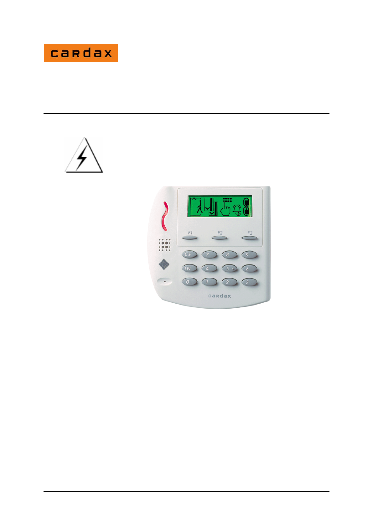
Cardax Prox Plus Mifare
Reader
CAUTION
This equipment contains components that can be damaged by
electrostatic discharge. Ensure both you and the equipment
are earthed before beginning any servicing.
Before you begin
Unpack the Prox Plus Mifare reader and check that you received the
following items:
1 x Base plate
1 x Reader assembly
1 x Interconnect board
1 x Four-pin Molex 6471 crimp-terminal socket equipped with
grommet and 400 mm flexible cord
Part number 3C4480 R10 1
May 2005

4 x Self-tapping pan-head screws
4 x 10 mm plastics screw caps
1 x M4 x 12 tamper-resistant Torx-head machine screw
Power supply requirements
Each Prox Plus Mifare reader consumes 200 mA from a 13.6 V
± 15% DC supply.
Use a linear-regulator power source.
Note:
Switch mode power supplies are not recommended as they may
reduce the read range of the Prox Plus Mifare reader.
Firmware
The reader firmware has two variants. These are set out in the
table.
Firmware identification Capability
vR1.06 and earlier Reads Philips Mifare 1K cards.
vR2.05 and later Reads Philips Mifare 1K cards
Depending on the type of firmware, there is a difference in the
sequence displayed on the reader's screen after power has been
applied.
Reads all sectors of Philips Mifare 4K cards
2 Part number 3C4480 R10
May 2005
vR1.nn vR2.nn
After power has been applied,
the reader:
Beeps
Displays each of its icons in
sequence
Displays the secure icon
After power has been applied,
the reader:
Beeps
Displays each of its icons in
sequence
Displays each of its icons in
.
sequence a second time
Displays all icons
simultaneously
Displays a blank screen for
about two seconds
Displays the secure icon
.
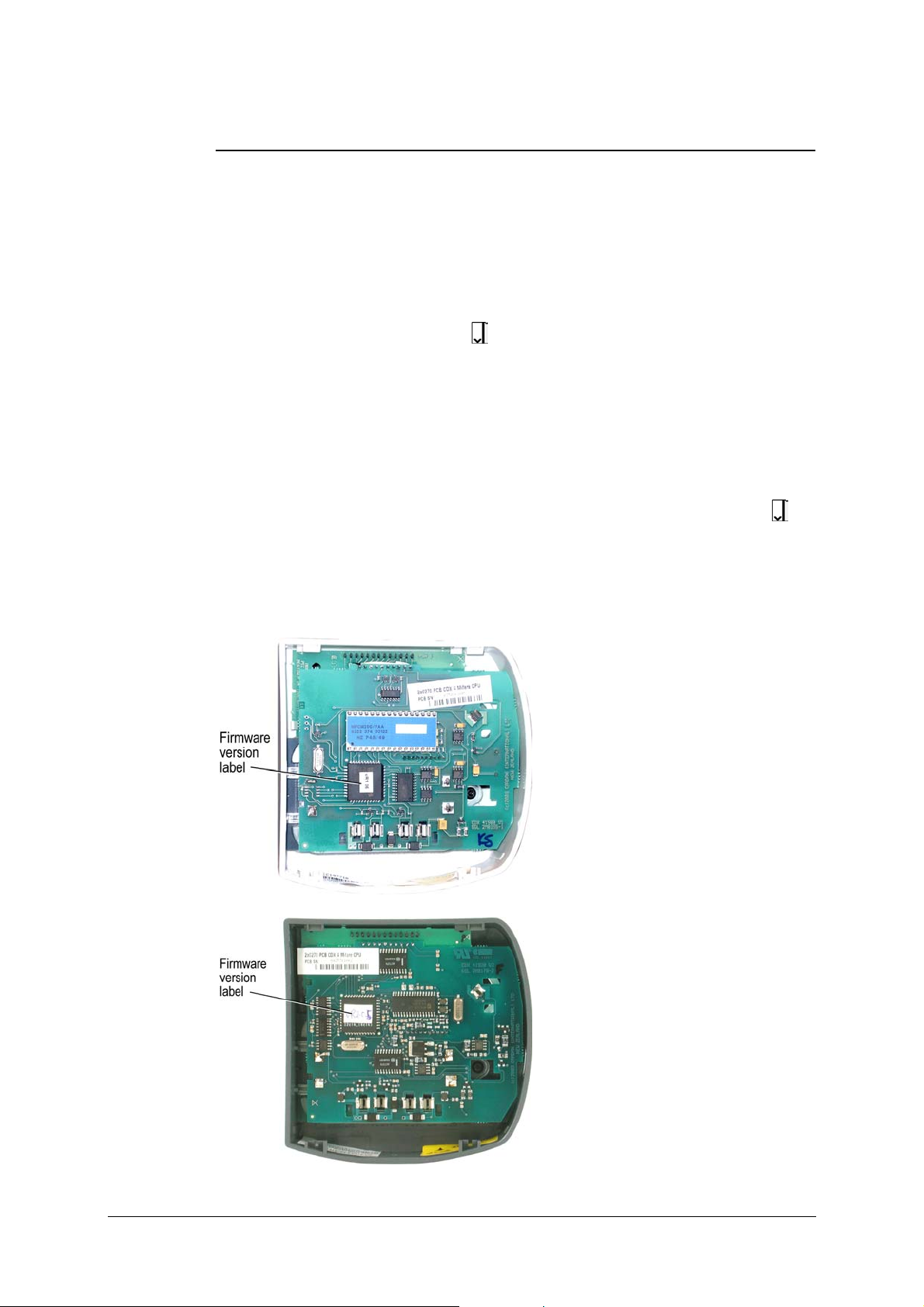
The version of firmware used by the reader is shown on a label
attached to the central processor integrated circuit. The diagrams
below show the location of the label for both variants of the reader.
(MFCM 200)
(MFRC500)
Part number 3C4480 R10 3
May 2005
Cabling
The Prox Plus Mifare reader uses the Cardax IV communications
system. It can be connected to the following equipment:
Cardax FT Controller 3000
Cardax FT Reader I/O Interface
Cardax FT URI
Use 4 core, 0.2 mm² (AWG 24) cabling with a maximum nominal
capacitance of 120 pF/m.
With this type of cable, the maximum distance between the Prox
Plus Mifare reader and the device to which it connects is 200 m
(650 ft).
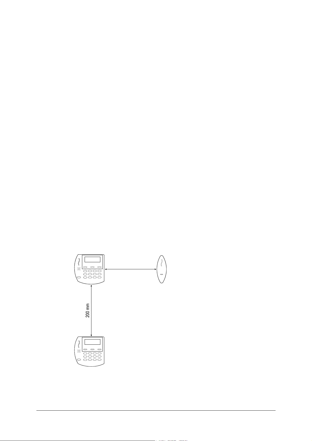
Distance between proximity readers
The distance separating any two proximity readers must not be less
than 200 mm in all directions.
200 mm
4 Part number 3C4480 R10
May 2005
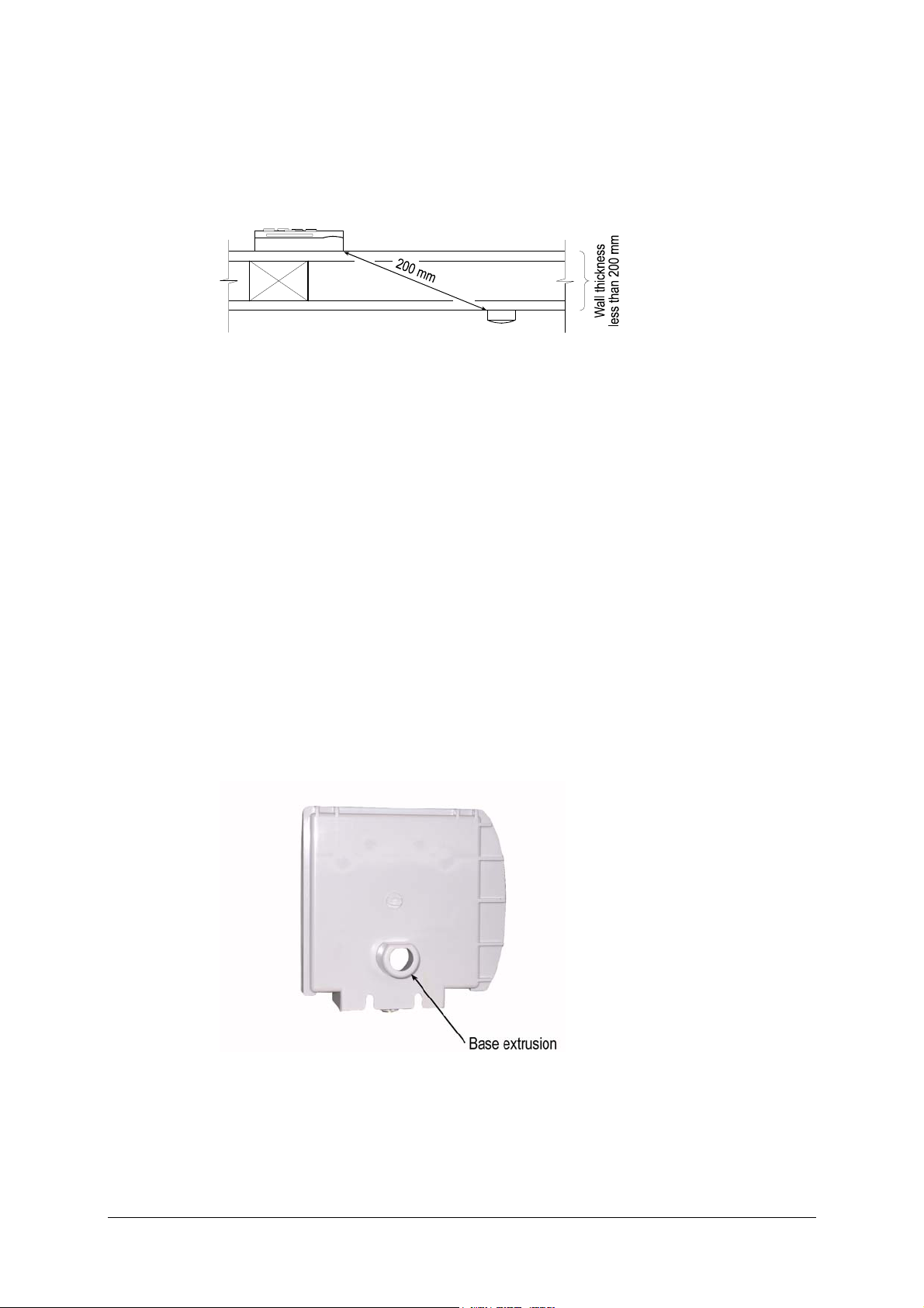
When mounting a proximity reader on an internal wall, check that
any reader fixed to the other side of the wall is not less than
200 mm away.
Attaching the base plate
Note:
The Prox Plus Mifare reader has been designed to metric
specifications. Any imperial measurements shown in this document
are approximate.
The Prox Plus Mifare reader is designed to be mounted on any solid
flat surface including metal surfaces.
The recommended mounting height for the Prox Plus Mifare reader
is 1100 mm from floor level to the centre of the reader device.
However this may vary in some countries and you should check
local regulations for variations to this height.
Drill a 20 mm (3/4 inch) diameter hole for the base extrusion
through or into the mounting surface to a minimum depth of 40 mm
(1½ inches).
Run the building cabling through the base.
Part number 3C4480 R10 5
May 2005

Press the base extrusion into the 20 mm (3/4 inch) hole and secure
the base to the mounting surface using the four fixing screws.
Fit the screw caps over each fixing screw. The screw caps prevent
water from entering the reader via the fixing holes. The caps must
be installed for the Prox Plus Mifare reader to comply with the
environmental specification.
Note:
It is very important that the base of the reader is flush with and tight
against the mounting surface. If you are mounting the Prox Plus
Mifare reader on a rough surface you should make the surface as
smooth as possible under the reader and up to 25 mm (1 inch)
around the reader.
Note:
The grommet through which the cables feed into the base of the
Prox Plus Mifare reader helps to keep the device waterproof.
6 Part number 3C4480 R10
May 2005

Connections
INTERCONNECT BOARD
(VIEWED FROM
CABLE SI DE OF CONNECTOR)
READER
INTERCONNECT BOARD
12 34
READER SIDE OF CONNECTOR)
1234
1
1
2
2
3
3
4
4
(VIEWED FROM
MOLEX 6471
CRIMP TERMINAL SOCKET
4321
(VIEWED FROM
CABLE SIDE OF SOCKET)
RED
1
2
WHITE
3
BLUE
BLACK
4
+12V
DATA OUT
DATA IN
-12V
FT CONTROLLER 3000;
FT READER I/O INTERFACE; OR
FT URI
You can connect the building cable to the reader in either of two
ways:
use the four-pin socket and cord supplied with the reader and
join the cord to the building cabling; or
provide your own Molex 6471 crimp terminal socket and
terminate the building cable directly to it.
In either case, ensure that you use the socket grommet supplied with
the reader.
If you supply your own socket, use the cable terminating tool. The
tool has a head (Part No. C861145) and handle (Part No. C861115).
Pin number 4 of the socket feeds into the cable terminating tool
first.
The other end of the building cable connects to one of the
following:
Cardax FT Controller 3000
Cardax FT Reader I/O Interface
Cardax FT URI
Part number 3C4480 R10 7
May 2005

Connecting to the Cardax FT Controller 3000
The Cardax FT Controller 3000 interfaces the following types of
reader into the Cardax FT Command Centre system:
Cardax IV readers, including Prox Plus Mifare readers
Wiegand readers
Each Cardax FT Controller 3000 can interface up to eight Prox Plus
Mifare readers into the Cardax FT Command Centre system.
The ports to which the Prox Plus Mifare reader can connect are set
up as four distinct groups (numbered 1 to 4). Each group provides
connection for two Prox Plus Mifare readers or other Cardax IV
readers. Refer to the following diagram for the location of the ports
on the Cardax FT Controller 3000.
P4
P4
RS485
P2
PF4
PF3
PF2
PF1 PE1
P3
DETECTOR
LED
PE4
PE3
PE2
PC1 to PC4
Inputs
pin 1 = Input 1
pin 2 = Ground
pin 3 = Input 2
PC4
PD4
PC4PD4
PC3
PD3
PC3
PD3
PC2
PD2
PD2
PC2
PC1
PD1
PD1
PC1
PB1 to PB4
2 x Cardax IV Readers
per connector
Reader 1 = pins 1 & 3
Reader 2 = pins 2 & 4
Pin 1 = Reader 1 t ransmit
Pin 2 = Reader 2 t ransmit
Pin 3 = Reader 1 rece ive
Pin 4 = Reader 2 rece ive
P1
RS485
J1 to J4
terminating resistors
PA4
PB4
PA4
POWER
OUT
PA3
PB3
PA3
POWER
OUT
PA2
PB2
PA2
POWER
OUT
PA1
PB1
PA1
POWER
OUT
Group 4
Group 3
Group 2
Group 1
PA1 to PA4
Power Out
pin 1 = power out
pin 2 = 0 V
Make the connections from the Prox Plus Mifare reader to the
Cardax FT Controller 3000 as shown:
8 Part number 3C4480 R10
May 2005

Controller 3000
Group (x4)
PB1 and PA1... to... PB4 and PA4
4 3 2 1
Prox Plus Mifare
Reader 2
PB
Prox Plus Mifare
Reader 1
PA
2 1
Note:
Within each group, you cannot mix Cardax IV readers with
Wiegand Readers. This is because connecting one Wiegand reader
requires all four pins on plug PB. For example, if you connect a
Prox Plus Mifare reader to Port 1 of Group 1, Port 2 of Group 1 can
only connect to another Cardax IV reader.
The terminating resistors (J1 for Group 1, J2 for Group 2, etc.) must
NOT be fitted for those groups to which Prox Plus Mifare readers
are connected.
Connecting to the Cardax FT Reader I/O Interface
The Cardax FT Reader I/O Interface has connections for up to
sixteen Prox Plus Mifare readers or other Cardax IV readers.
The Prox Plus Mifare reader connects to either plug PA or PB in
Groups 1 to 8.
Make the connections from the Prox Plus Mifare reader to the
Reader I/O interface as shown:
Part number 3C4480 R10 9
May 2005

Prox Plus Mifare Readers
Red
1
White
2
Blue
3
Black
4
Red
1
White
2
Blue
3
Black
4
Reader I/O Interface
Group (x8)
IN
Reader A
OUT
IN
OUT
(PA)
Reader B
(PB)
+V
Power
0
(PD)
For the location of the plugs on the Reader I/O Interface, refer to
the component layout diagram:
10 Part number 3C4480 R10
May 2005

Connecting to the Cardax FT URI
Connect the cables to the socket as shown.
Cardax FT Universal Reader Interface
P2 Non-CardaxFT
Reader 2
pin 1 = 5/12 V power
pin 2 = DataA
pin 3 = DataB
pin 4 = Card detect
pin 5 = LED output
pin 6 = Beeper output
pin 7 = Ground
Prox Plus Mifare Connector
Black
4
Blue
3
White
2
Red
1
Plug P1 or P2
GND
OUTPUTS
OUTPUTS
DET
COMMS
COMMS
5/12V
Connect the Prox Plus Mifare reader connector to either the P1 or
P2 plug on the Cardax FT URI. Refer to the Cardax FT URI
component layout diagram, next, for the location of the plugs.
T1
D17
NC NO
COIL
COMM
D21
NC NO
COIL
RLY2
COMM
D18
P5
Power & Comms
pins 1 & 2 = RS485
pin 3 = 13.6 V ± 15%
pin 4 = 0V
JP1
Reader Voltage select
D17 and D21
Relay state indicators
LED on = Energised
LED off = De-energised
P7
Relay Outputs
R1 p1 = Normally closed
R1 p2 = Normally open
R1 p3 = Common
R2 p4 = Normally closed
R2 p5 = Normally open
R2 p6 = Common
p7 = Ground
= 12V (1A total)
P3
Keypad
pin 1 = Row1
pin 2 = Row 2
pin 3 = Row 3
pin 4 = Row 4
pin 5 = Column1
pin 6 = Column2
pin 7 = Column3
pin 8 = Ground
P2
P6
13.6 V ± 15% out
pin 1 = 13.6 V ± 15%
pin 2 = Ground
3A fused
F2 3A
13.6 V ± 15%out
F1 500mA
13.6 V ± 15%in
D10 Comms
LED flashing =
communicating with
FT Controller
D10
E
5V
JP1
12V
D18
Run LED
P1
(c)1999 PEC(New Zealand) Ltd
Non-CardaxFT
P1
Reader 1
pin 1 = 5/12 V power
pin 2 = DataA
pin 3 = DataB
pin 4 = Card detect
pin 5 = LED output
pin 6 = Beeper output
pin 7 = Ground
210
1
P8
Diagnostic port
P8
9
SW1
Device address
Set device number
SW1
22825V2 Assy 22826
P4
Balanced Inputs
pin 1 = Input1
pin 2 = Input 2
pin 3 = Input 3
pin 4 = Input 4
pin 5 = Input 5
pin 6 = Input 6
pin 7 = Ground
REV[A][B][C]
Part number 3C4480 R10 11
May 2005

Fitting the facia
1. Press the Molex 6471 socket onto the four pin plug on the
interconnect board.
2. Push the interconnect board into the base plate so that the
Molex 6471 socket beds into the grommet.
3. Push the interconnect board further until it is captured by the
clips on the base plate.
4. Slide the facia attachment lugs into the guides at the rear of the
base plate.
5. On the front of the facia, press down on the Cardax label until
the security screw hole lines up with the M4 threaded hole
underneath the base plate.
6. Pass the M4 security screw through the hole in the facia and use
a tamper-resistant Torx-head tool to drive it into the threaded
hole in the base plate.
Removing the facia
1. Using a tamper-resistant Torx-head tool, remove the M4
security screw from the underside of the facia.
2. Pull the base of the facia away from the base plate.
3. Slide the facia's attachment lugs out of the guides at the rear of
the base plate.
12 Part number 3C4480 R10
May 2005

Initialisation
Initialising with the Cardax FT Controller 3000
Refer to the Cardax FT Controller 3000 Installation Note (Part
number 3E1089) for initialisation instructions.
Initialisation of the Cardax FT Controller 3000 does not require
prior connection to the Prox Plus Mifare reader. The Prox Plus
Mifare reader will be operational as soon as it is:
connected to a Cardax FT Controller 3000, and
configured as a Cardax IV reader within the Cardax FT
Command Centre system.
Initialising with the Cardax FT Reader I/O Interface
Refer to the Cardax FT Reader I/O Interface Installation Note
(Gallagher Part number 3E1016) for initialisation instructions.
Initialisation of the Cardax FT Reader I/O Interface does not require
prior connection to the Prox Plus Mifare reader. The Prox Plus
Mifare reader will be operational as soon as it is:
connected to a Cardax FT Reader I/O Interface, and
configured as a Cardax IV reader within the Cardax FT
Command Centre system.
Initialising with the Cardax FT URI
Refer to the Cardax FT Universal Reader Interface Installation
Note (Gallagher Part number 3C4518) for initialisation instructions.
Initialisation of the Cardax FT URI does not require prior
connection to the Prox Plus Mifare reader. The Prox Plus Mifare
reader will be operational as soon as it is:
connected to a Cardax FT URI, and
configured as a Cardax IV reader within the Cardax FT
Command Centre system.
Part number 3C4480 R10 13
May 2005

Icons
The Prox Plus Mifare reader displays the following icons on the
liquid crystal display (LCD) to indicate the access status of the zone
controlled by the reader.
14 Part number 3C4480 R10
May 2005

Approvals and Standards
This equipment has been tested and found to comply with the limits
for a Class B digital device, pursuant to Part 15 of the FCC Rules.
These limits are designed to provide reasonable protection against
harmful interference in a residential installation. This equipment
generates, uses and can radiate radio frequency energy and, if not
installed and used in accordance with the instructions, may cause
harmful interference to radio communications. However, there is no
guarantee that interference will not occur in a particular installation.
If this equipment does cause harmful interference to radio or
television reception, which can be determined by turning the
equipment off and on, the user is encouraged to try to correct the
interference by one or more of the following measures:
Reorient or relocate the receiving antenna.
Increase the separation between the equipment and receiver.
Connect the equipment into an outlet on a circuit different from
that to which the receiver is connected.
Consult the dealer or an experienced radio/TV technician for
help.
Note: Changes or modifications not expressly approved by
Gallagher Security Management Systems could void the
user's authority to operate the equipment.
ACN: 002132943
Part number 3C4480 R10 15
May 2005

PUBLISHED BY
Gallagher Group Limited
Kahikatea Drive, Private Bag 3026
Hamilton, New Zealand
Copyright© Gallagher Group Limited 2004.
All rights reserved. Patents Pending.
3C4480
R10
May 2005
DISCLAIMER Whilst every effort has
been made to ensure accuracy, neither
Gallagher Group Limited nor any
employee of the company, shall be liable
on any ground whatsoever to any party in
respect of decisions or actions they may
make as a result of using this information.
In accordance with the Gallagher policy of
continuing development, design and
specifications are subject to change
without notice.
Developed and manufactured by
Gallagher Group Limited, an ISO
9001:2000 Certified Supplier.
 Loading...