


DMC-40x0
Manual Rev. 1.0w
USER MANUAL
Galil Motion Control, Inc.
270 Technology Way
Rocklin, California
916.626.0101
support@galil.com
galil.com
01/2017

Using This Manual
4080
This user manual provides information for proper operation of the DMC-40x0 controller. A separate supplemental
manual, the Command Reference, contains a description of the commands available for use with this controller. It
is recommended that the user download the latest version of the Command Reference and User Manual from the
Galil Website.
http://www.galilmc.com/support/manuals.php
Your DMC-40x0 motion controller has been designed to work with both servo and stepper type motors.
Installation and system setup will vary depending upon whether the controller will be used with stepper motors or
servo motors. To make finding the appropriate instructions faster and easier, icons will be next to any information
that applies exclusively to one type of system. Otherwise, assume that the instructions apply to all types of
systems. The icon legend is shown below.
Attention: Pertains to servo motor use.
Attention: Pertains to stepper motor use.
Attention: Pertains to controllers with more than 4 axes.
Please note that many examples are written for the DMC-4040 four-axes controller or the DMC-4080 eight axes
controller. Users of the DMC-4030 3-axis controller, DMC-4020 2-axes controller or DMC-4010 1-axis controller
should note that the DMC-4030 uses the axes denoted as ABC, the DMC-4020 uses the axes denoted as AB, and the
DMC-4010 uses the A-axis only.
Examples for the DMC-4080 denote the axes as A,B,C,D,E,F,G,H. Users of the DMC-4050 5-axes controller. DMC4060 6-axes controller or DMC-4070, 7-axes controller should note that the DMC-4050 denotes the axes as
A,B,C,D,E, the DMC-4060 denotes the axes as A,B,C,D,E,F and the DMC-4070 denotes the axes as A,B,C,D,E,F,G. The
axes A,B,C,D may be used interchangeably with X, Y, Z, W.
Machinery in motion can be dangerous!
WARNING
It is the responsibility of the user to design effective error handling and safety protection as
part of the machinery. Galil shall not be liable or responsible for any incidental or
consequential damages
DMC-40x0 Contents ▫ i

Contents
Contents iii
Chapter 1 Overview 1
Chapter 2 Getting Started 10
Chapter 3 Connecting Hardware 33
Introduction ................................................................................................................... 1
Part Numbers ................................................................................................................ 2
Overview of Motor Types ............................................................................................. 5
Overview of External Amplifiers .................................................................................. 6
Galil Internal Amplifiers and Drivers ........................................................................... 6
Functional Elements ...................................................................................................... 7
Layout ........................................................................................................................... 10
Power Connections ....................................................................................................... 12
Dimensions ................................................................................................................... 13
Elements You Need ....................................................................................................... 15
Installing the DMC, Amplifiers, and Motors ................................................................ 16
Overview ....................................................................................................................... 33
Overview of Optoisolated Inputs .................................................................................. 33
Optoisolated Input Electrical Information .................................................................... 36
High Power Optoisolated Outputs ................................................................................ 39
TTL Inputs and Outputs ................................................................................................ 40
Analog Inputs ................................................................................................................ 42
Extended I/O ................................................................................................................. 42
External Amplifier Interface ......................................................................................... 43
Chapter 4 Software Tools and Communication 50
Introduction ................................................................................................................... 50
Controller Response to Commands .............................................................................. 50
Unsolicited Messages Generated by Controller ............................................................ 51
Serial Communication Ports ......................................................................................... 51
Ethernet Configuration .................................................................................................. 53
Modbus ......................................................................................................................... 55
Data Record .................................................................................................................. 58
GalilSuite (Windows and Linux) .................................................................................. 64
Creating Custom Software Interfaces ........................................................................... 65
Chapter 5 Command Basics 67
Introduction ................................................................................................................... 67
Command Syntax - ASCII ............................................................................................ 67
Controller Response to DATA ...................................................................................... 68
Interrogating the Controller .......................................................................................... 69
Chapter 6 Programming Motion 71
Overview ....................................................................................................................... 71
Independent Axis Positioning ....................................................................................... 72
Independent Jogging ..................................................................................................... 74
Position Tracking .......................................................................................................... 75
Linear Interpolation Mode ............................................................................................ 79
Vector Mode: Linear and Circular Interpolation Motion .............................................. 82
Electronic Gearing ........................................................................................................ 89
Electronic Cam .............................................................................................................. 92
PVT Mode ..................................................................................................................... 97
Contour Mode ............................................................................................................... 100
DMC-40x0 Contents ▫ ii

Virtual Axis ................................................................................................................... 104
Stepper Motor Operation .............................................................................................. 105
Stepper Position Maintenance Mode (SPM) ................................................................. 107
Dual Loop (Auxiliary Encoder) .................................................................................... 110
Motion Smoothing ....................................................................................................... 112
Homing ......................................................................................................................... 114
High Speed Position Capture (The Latch Function) .................................................... 116
Chapter 7 Application Programming 117
Overview ....................................................................................................................... 117
Program Format ............................................................................................................ 117
Executing Programs - Multitasking .............................................................................. 119
Debugging Programs .................................................................................................... 120
Program Flow Commands ............................................................................................ 121
Mathematical and Functional Expressions ................................................................... 136
Variables ........................................................................................................................ 139
Operands ....................................................................................................................... 140
Arrays ............................................................................................................................ 141
Input of Data (Numeric and String) .............................................................................. 144
Output of Data (Numeric and String) ........................................................................... 146
Hardware I/O ................................................................................................................ 150
Extended I/O of the DMC-40x0 Controller .................................................................. 154
Example Applications ................................................................................................... 156
Using the DMC Editor to Enter Programs .................................................................... 160
Chapter 8 Hardware & Software Protection 162
Introduction ................................................................................................................... 162
Hardware Protection ..................................................................................................... 162
Software Protection ....................................................................................................... 163
Chapter 9 Troubleshooting 167
Overview ....................................................................................................................... 167
Chapter 10 Theory of Operation 170
Overview ....................................................................................................................... 170
Operation of Closed-Loop Systems .............................................................................. 172
System Modeling .......................................................................................................... 173
System Analysis ............................................................................................................ 177
System Design and Compensation ................................................................................ 179
Appendices 182
Electrical Specifications ................................................................................................ 182
Performance Specifications .......................................................................................... 184
Ordering Options .......................................................................................................... 185
Power Connector Part Numbers .................................................................................... 192
Input Current Limitations ............................................................................................. 193
Serial Cable Connections .............................................................................................. 194
Configuring the Amplifier Enable Circuit .................................................................... 196
Signal Descriptions ....................................................................................................... 206
List of Other Publications ............................................................................................. 208
Training Seminars ......................................................................................................... 208
Contacting Us ................................................................................................................ 209
WARRANTY ................................................................................................................ 210
Integrated Components 211
Overview ....................................................................................................................... 211
A1 – AMP-430x0 (-D3040,-D3020) 213
Description .................................................................................................................... 213
Electrical Specifications ................................................................................................ 214
Operation ....................................................................................................................... 215
Error Monitoring and Protection ................................................................................... 217
DMC-40x0 Contents ▫ iii

A2 – AMP-43140 (-D3140) 219
Description .................................................................................................................... 219
Electrical Specifications ................................................................................................ 220
Operation ....................................................................................................................... 221
A3 – AMP-43240 (-D3240) 222
Description .................................................................................................................... 222
Electrical Specifications ................................................................................................ 223
Operation ....................................................................................................................... 224
Error Monitoring and Protection ................................................................................... 225
A4 – AMP-435x0 (-D3540,-D3520) 228
Description .................................................................................................................... 228
Electrical Specifications ................................................................................................ 229
Operation ....................................................................................................................... 230
Error Monitoring and Protection ................................................................................... 233
A5 – AMP-43640 (-D3640) 235
Introduction ................................................................................................................... 235
Electrical Specifications ................................................................................................ 236
Operation ....................................................................................................................... 238
A6 – AMP-43740 (-D3740) 241
Description .................................................................................................................... 241
Electrical Specifications ................................................................................................ 242
Operation ....................................................................................................................... 243
Error Monitoring and Protection ................................................................................... 245
A7 – SDM-440x0 (-D4040,-D4020) 247
Description .................................................................................................................... 247
Electrical Specifications ................................................................................................ 248
Operation ....................................................................................................................... 249
A8 – SDM-44140 (-D4140) 251
Description .................................................................................................................... 251
Electrical Specifications ................................................................................................ 252
Operation ....................................................................................................................... 253
Error Monitoring and Protection ................................................................................... 254
A9 – CMB-41012 (-C012) 255
Description .................................................................................................................... 255
Connectors for CMB-41012 Interconnect Board ......................................................... 256
A10 – CMB-41022 (-C022) 259
Description .................................................................................................................... 259
Connectors for CMB-41022 Interconnect Board ......................................................... 260
A11 – ICM-42000 (-I000) 264
Description .................................................................................................................... 264
Connectors for ICM-42000 Interconnect Board ........................................................... 265
A12 – ICM-42100 (-I100) 268
Description .................................................................................................................... 268
Connectors for ICM-42100 Interconnect Board ........................................................... 269
Theory of Operation ...................................................................................................... 272
A13 – ICM-42200 (-I200) 275
Description .................................................................................................................... 275
Connectors for ICM-42200 Interconnect Board ........................................................... 276
DMC-40x0 Contents ▫ iv

Chapter 1 Overview
Introduction
The DMC-40x0 Series are Galil’s highest performance stand-alone controller. The controller series offers many
enhanced features including high speed communications, non-volatile program memory, faster encoder speeds,
and improved cabling for EMI reduction.
Each DMC-40x0 provides two communication channels: high speed RS-232 (2 channels up to 115K Baud) and 100
BaseT Ethernet. The controllers allow for high-speed servo control up to 22 million encoder counts/sec and step
motor control up to 6 million steps per second. Sample rates as low as 31.25 µsec per axis are available.
A Flash EEPROM provides non-volatile memory for storing application programs, parameters, arrays and firmware.
New firmware revisions are easily upgraded in the field.
The DMC-40x0 is available with up to eight axes in a single stand alone unit. The DMC-4010, 4020, 4030, 4040 are
one thru four axes controllers and the DMC-4050, 4060, 4070, 4080 are five thru eight axes controllers. All eight
axes have the ability to use Galil’s integrated amplifiers or drivers and connections for integrating external devices.
Designed to solve complex motion problems, the DMC-40x0 can be used for applications involving jogging, pointto-point positioning, vector positioning, electronic gearing, multiple move sequences, contouring and a PVT Mode.
The controller eliminates jerk by programmable acceleration and deceleration with profile smoothing. For smooth
following of complex contours, the DMC-40x0 provides continuous vector feed of an infinite number of linear and
arc segments. The controller also features electronic gearing with multiple master axes as well as gantry mode
operation.
For synchronization with outside events, the DMC-40x0 provides uncommitted I/O, including 8 optoisolated digital
inputs (16 inputs for DMC-4050 thru DMC-4080), 8 high power optically isolated outputs (16 outputs for DMC-4050
thru DMC-4080), and 8 analog inputs for interface to joysticks, sensors, and pressure transducers. The DMC-40x0
also has an additional 32 I/O at 3.3V logic. Further I/O is available if the auxiliary encoders are not being used (2
inputs / each axis). Dedicated optoisolated inputs are provided for forward and reverse limits, abort, home, and
definable input interrupts.
Commands are sent in ASCII. Additional software is available for automatic-tuning, trajectory viewing on a PC
screen, and program development using many environments such as Visual Basic, C, C++ etc. Drivers for Windows
XP, Vista and 7 (32 & 64 bit) as well as Linux are available.
Chapter 1 Overview ▫ 1 DMC-40x0 User Manual

Part Numbers
The DMC-40x0 is modular by nature, meaning that a customer must specify several components in order to create
a full part number. The user must specify the main control board (DMC), the communication board (CMB), and the
interconnect module (ICM) to have a complete unit. The user can also specify an optional internal amplifier (AMP
or SDM). How these models stack up internally is shown in Figure 1.1 for 1-4 axis models.
Figure 1.1: Abstract internal layout of the DMC-40x0 for 1-4 axis models
For 5-8 axis models, the user must also specify an additional ICM and optional internal amplifier type for axis 5-8 as
shown in Figure 1.2.
Figure 1.2: Abstract internal layout of the DMC-40x0 for 5-8 axis models
Each module has it's own set of part numbers and configuration options that make the full part number of a DMC40x0 unit. The DMC has the part number format “DMC-40X0(Y),” the CMB is “-CXXX(Y),” the ICM is “-IXXX(Y),” and
the AMP/SDM is “-DXXX(Y),” where X designates different module options and Y designates different configuration
options for these modules. The full DMC-40x0 part number would be the full string of individual module part
numbers combined as shown for 1-4 and 5-8 axis models in Figure 1.3.
Chapter 1 Overview ▫ 2 DMC-40x0 User Manual

Figure 1.3: Layout of a complete DMC-40x0 part number
The placement of ICM and AMP/SDM options is extremely important for 5-8 axis models. Reading left to right, the
first ICM (Axis 1-4) will be placed in the ICM (1) spot in Figure 1.2 and the second ICM (Axis 5-8) will be placed in
the ICM (2) spot. This also follows for AMP/SDM placement.
If the part number is not readily available, you can determine the information by using the 'ID' command. Issuing
an 'ID' command when connected to the controller will return your controller's internal hardware configuration.
The CMB and ICM module options effect the pin-outs of the DMC-40x0.
WARNING
Use Table 1.2 and Table 1.3 below to determine your CMB and ICM part numbers then refer to the
appropriate documentation for your pin-outs before connecting any hardware.
DMC, “DMC-40X0(Y)” Options
Option Type Options
X 1,2,3,4,5,6,7, and 8 Number of control axis N/A
Y DIN DIN Rail Mount DMC, “DMC-40X0(Y)” Controller Board
12V Power Controller with 12 VDC
-16bit 16-bit analog inputs
4-20mA 4-20mA analog inputs
ISCNTL Isolate Controller Power
TRES Encoder terminating resistors
ETL ETL certification
MO Motor off jumper installed
Table 1.1: Controller board, DMC, “DMC-40X0(Y)” options
Chapter 1 Overview ▫ 3 DMC-40x0 User Manual
Brief Description Documentation
Options, starting on pg 185.

CMB, “-CXXX(Y)” Options
Option Type Options Brief Description Documentation
XXX 012 Default communication board A9 – CMB-41012 (-C012), pg 255
022 Dual-Ethernet communication board A10 – CMB-41022 (-C022), pg 259
Y 5V SSI Feedback 5V – Configure Extended I/O for 5V logic, pg
187
P422 RS-422 on Main and Aux serial port RS-422 – Serial Port Serial Communication, pg
P1422 RS-422 on Main serial port only
187
P2422 RS-422 on Aux serial port only
Table 1.2: Communication board, CMB “-CXXX(Y)” options
ICM, “-IXXX(Y)” Options
Option Type Options Brief Description Documentation
XXX 000 Default interconnect board A11 – ICM-42000 (-I000), pg 264
100 Sine/Cosine feedback interconnect board A12 – ICM-42100 (-I100), pg 268
200 26-pin encoder connecter interconnect board A13 – ICM-42200 (-I200),pg 275
Y SSI SSI Feedback ICM, “-IXXX(Y)” Interconnect Board Options,
BiSS BiSS Feedback
DIFF Differential ±10 motor command outputs
STEP Differential STEP/DIR outputs
starting on pg 188
Table 1.3: Interconnect module, ICM “-IXXX(Y)” options
AMP/SDM, “-DXXXX(Y)” Options
Option Type Options Brief Description Documentation
XXXX 3020/3040 500 W trapazoidal servo drive
2 and 4-axis models
3140 20 W brush-type only drive A2 – AMP-43140 (-D3140), pg 219
3240 750 W trapazoidal servo drive A3 – AMP-43240 (-D3240), pg 222
3520/3540 600 W sinusoidal servo drive
2 and 4-axis models
3640 20 W sinusoidal servo drive A5 – AMP-43640 (-D3640), pg 235
4040/4020 1.4 A with 1/16 microstepping drive A7 – SDM-440x0 (-D4040,-D4020), pg 247
4140 3 A with 1/64 microstepping drive A8 – SDM-44140 (-D4140), pg 251
Y 100mA 100mA current
-D3140 option only
SSR Solid state relay
HALLF Filtered hall sensors
1
1
ISAMP Isolates power between amplifiers
Two banks of AMP/SDMs required
A1 – AMP-430x0 (-D3040,-D3020), pg 213
A4 – AMP-435x0 (-D3540,-D3520), pg 228
AMP/SDM, “-DXXXX(Y)” Internal Amplifier Options,
starting on pg 190
1
Not available for all amplifier options, see the
proper documentation in Ordering Options.
Table 1.4: Amplifier options, AMP/SDM “-DXXXX(Y)”
Chapter 1 Overview ▫ 4 DMC-40x0 User Manual

Overview of Motor Types
The DMC-40x0 can provide the following types of motor control:
1. Standard servo motors with ± 10 volt command signals
2. Brushless servo motors with sinusoidal commutation
3. Step motors with step and direction signals
4. Other actuators such as hydraulics and ceramic motors - For more information, contact Galil.
The user can configure each axis for any combination of motor types, providing maximum flexibility.
Standard Servo Motor with ±10 Volt Command Signal
The DMC-40x0 achieves superior precision through use of a 16-Bit motor command output DAC and a sophisticated
PID filter that features velocity and acceleration feed-forward, an extra pole filter and integration limits.
The controller is configured by the factory for standard servo motor operation. In this configuration, the controller
provides an analog signal (±10 volts) to connect to a servo amplifier. This connection is described in Chapter 2.
Brushless Servo Motor with Sinusoidal Commutation
The DMC-40x0 can provide sinusoidal commutation for brushless motors (BLM). In this configuration, the
controller generates two sinusoidal signals for connection with amplifiers specifically designed for this purpose.
Note: The task of generating sinusoidal commutation may be accomplished in the brushless motor amplifier. If the
amplifier generates the sinusoidal commutation signals, only a single command signal is required and the controller
should be configured for a standard servo motor (described above).
Sinusoidal commutation in the controller can be used with linear and rotary BLMs. However, the motor velocity
should be limited such that a magnetic cycle lasts at least 6 milliseconds with a standard update rate of 1
millisecond. For faster motors, please contact the factory.
To simplify the wiring, the controller provides a one-time, automatic set-up procedure. When the controller has
been properly configured, the brushless motor parameters may be saved in non-volatile memory.
The DMC-40x0 can control BLMs equipped with Hall sensors as well as without Hall sensors. If Hall sensors are
available, once the controller has been setup, the brushless motor parameters may be saved in non-volatile
memory. In this case, the controller will automatically estimate the commutation phase upon reset. This allows
the motor to function immediately upon power up. The Hall effect sensors also provide a method for setting the
precise commutation phase. Chapter 2 describes the proper connection and procedure for using sinusoidal
commutation of brushless motors.
Stepper Motor with Step and Direction Signals
The DMC-40x0 can control stepper motors. In this mode, the controller provides two signals to
connect to the stepper motor: Step and Direction. For stepper motor operation, the controller does
not require an encoder and operates the stepper motor in an open loop fashion. Chapter 2 describes
the proper connection and procedure for using stepper motors.
If encoders are available on the stepper motor, Galil’s Stepper Position Maintenance Mode may be
used for automatic monitoring and correction of the stepper position. See Stepper Position
Maintenance Mode (SPM) in Chapter 6 for more information.
Chapter 1 Overview ▫ 5 DMC-40x0 User Manual

Overview of External Amplifiers
The amplifiers should be suitable for the motor and may be linear or pulse-width-modulated. An amplifier may
have current feedback, voltage feedback or velocity feedback.
Amplifiers in Current Mode
Amplifiers in current mode should accept an analog command signal in the ±10 volt range. The amplifier gain
should be set such that a +10V command will generate the maximum required current. For example, if the motor
peak current is 10A, the amplifier gain should be 1 A/V.
Amplifiers in Velocity Mode
For velocity mode amplifiers, a command signal of 10 volts should run the motor at the maximum required speed.
The velocity gain should be set such that an input signal of 10V runs the motor at the maximum required speed.
Stepper Motor Amplifiers
For step motors, the amplifiers should accept step and direction signals.
Galil Internal Amplifiers and Drivers
With the DMC-40x0 Galil offers a variety of Servo Amplifiers and Stepper Drivers that are integrated into the same
enclosure as the controller. Using the Galil Amplifiers and Drivers provides a simple straightforward motion control
solution in one box. Instead of having to route a +/-10V motor command signal, or STEP/DIR to some external box,
all the wiring is taken care of internally. In addition, Galil's internal amplifiers reside inside the same box as the
controller, ICM, and communication board (see Part Numbers, pg 2) saving real estate space and the hassle of
configuring a separate device.
A full list of amplifier specifications and details can be found in the Integrated Components, starting on pg 211.
Chapter 1 Overview ▫ 6 DMC-40x0 User Manual

Functional Elements
WATCHDOG T IMER
RISC BASED
MICROCOMPUT ER
HIGH-SPEED
MOTOR/ENCODE R
INTERFACE
FOR
A,B,C,D
I/O INTERFACE
ETHERNET
RS-232 / RS-422
8 UNCOMMITT ED
ANALOG INPUT S
HIGH-SPEED LATCH FOR EACH AXIS
ISOLATED LIMI TS AND
HOME INPUTS
MAIN ENCODE RS
AUXILIARY EN CODERS
+/- 10 VOLT OUTPUT FOR
SERVO MOTO RS
PULSE/DIRE CTION OUTPUT
FOR STEP MOTORS
HIGH SPEED ENC ODER
COMPARE OUT PUT
8 PROGRAMMAB LE,
OPTOISOLATE D
INPUTS
8 PROGRAMMABL E
HIGH POWER OPTOISOLATED
OUTPUT S
32 Configurable I/O
The DMC-40x0 circuitry can be divided into the following functional groups as shown in Figure 1.4 and discussed
below.
Figure 1.4: DMC-40x0 Functional Elements
Microcomputer Section
The main processing unit of the controller is a specialized Microcomputer with RAM and Flash EEPROM. The RAM
provides memory for variables, array elements, and application programs. The flash EEPROM provides non-volatile
storage of variables, programs, and arrays. The Flash also contains the firmware of the controller, which is field
upgradeable.
Motor Interface
Galil’s GL-1800 custom, sub-micron gate array performs quadrature decoding of each encoder at up to 22 MHz. For
standard servo operation, the controller generates a ±10 volt analog signal (16-bit DAC). For sinusoidal
commutation operation, the controller uses two DACs to generate two ±10 volt analog signals. For stepper motor
operation, the controller generates a step and direction signal.
Communication
The communication interface with the DMC-40x0 consists of high speed RS-232 and Ethernet. The Ethernet is
10/100Bt and the two RS-232 channels can generate up to 115K. An additional Ethernet port is available with the
CMB-41022, see A10 – CMB-41022 (-C022), pg 259 for details.
General I/O
The DMC-40x0 provides interface circuitry for 8 bi-directional, optoisolated inputs, 8 high power optoisolated
outputs and 8 analog inputs with 12-Bit ADC (16-Bit optional). The DMC-40x0 also has an additional 32 I/O (3.3V
Chapter 1 Overview ▫ 7 DMC-40x0 User Manual

logic) and unused auxiliary encoder inputs may also be used as additional inputs (2 inputs / each axis). The general
4080
inputs as well as the index pulse can also be used as high speed latches for each axis. A high speed encoder
compare output is also provided.
The DMC-4050 through DMC-4080 controller provides an additional 8 optoisolated inputs and 8 high
power optoisolated outputs.
System Elements
As shown in Figure 1.5, the DMC-40x0 is part of a motion control system which includes amplifiers, motors and
encoders. These elements are described below.
Power Supply
Computer DMC-40x0 Controller
Encoder Motor
Figure 1.5: Elements of Servo systems
Amplifier (Driver)
Motor
A motor converts current into torque which produces motion. Each axis of motion requires a motor sized properly
to move the load at the required speed and acceleration. (Galil’s MotorSizer Web tool can help you with motor
sizing: www.galilmc.com/support/motorsizer)
The motor may be a step or servo motor and can be brush-type or brushless, rotary or linear. For step motors, the
controller can be configured to control full-step, half-step, or microstep drives. An encoder is not required when
step motors are used.
Other motors and devices such as Ultrasonic Ceramic motors and voice coils can be controlled with the DMC-40x0.
Amplifier (Driver)
For each axis, the power amplifier converts a ±10 volt signal from the controller into current to drive the motor.
For stepper motors, the amplifier converts step and direction signals into current. The amplifier should be sized
properly to meet the power requirements of the motor. For brushless motors, an amplifier that provides electronic
commutation is required or the controller must be configured to provide sinusoidal commutation. The amplifiers
may be either pulse-width-modulated (PWM) or linear. They may also be configured for operation with or without
a tachometer. For current amplifiers, the amplifier gain should be set such that a 10 volt command generates the
maximum required current. For example, if the motor peak current is 10A, the amplifier gain should be 1 A/V. For
velocity mode amplifiers, 10 volts should run the motor at the maximum speed.
Galil offers amplifiers that are integrated into the same enclosure as the DMC-40x0. See the Integrated section in
the Appendices or http://galilmc.com/products/accelera/dmc40x0.html for more information.
Chapter 1 Overview ▫ 8 DMC-40x0 User Manual

Encoder
An encoder translates motion into electrical pulses which are fed back into the controller. The DMC-40x0 accepts
feedback from either a rotary or linear encoder. Typical encoders provide two channels in quadrature, known as
MA and MB. This type of encoder is known as a quadrature encoder. Quadrature encoders may be either singleended (MA+ and MB+) or differential (MA+, MA-, MB+, and MB-). The DMC-40x0 decodes either type into
quadrature states or four times the number of cycles. Encoders may also have a third channel (or index) for
synchronization.
The DMC-40x0 can be ordered with 120 Ω termination resistors installed on the encoder inputs. See the Ordering
Options in the Appendix for more information.
The DMC-40x0 can also interface to encoders with pulse and direction signals. Refer to the “CE” command in the
command reference for details.
There is no limit on encoder line density; however, the input frequency to the controller must not exceed 5,500,000
full encoder cycles/second (22,000,000 quadrature counts/sec). For example, if the encoder line density is 10,000
cycles per inch, the maximum speed is 550 inches/second. If higher encoder frequency is required, please consult
the factory.
The standard encoder voltage level is TTL (0-5v), however, voltage levels up to 12 Volts are acceptable. (If using
differential signals, 12 Volts can be input directly to the DMC-40x0. Single-ended 12 Volt signals require a bias
voltage input to the complementary inputs).
The DMC-40x0 can accept analog feedback (±10v) instead of an encoder for any axis. For more information see the
command AF in the command reference.
To interface with other types of position sensors such as absolute encoders, Galil can customize the controller and
command set. Please contact Galil to talk to one of our applications engineers about your particular system
requirements.
Sinusoidal Encoders
The DMC-40x0 can be ordered with an interconnect module that supports the use of 1Vp-p sinusoidal encoders.
This interconnect module is the ICM-42100. See A12 – ICM-42100 (-I100) in the Appendix for more information.
Watch Dog Timer
The DMC-40x0 provides an internal watch dog timer which checks for proper microprocessor operation. The timer
toggles the Amplifier Enable Output (AMPEN) which can be used to switch the amplifiers off in the event of a
serious DMC-40x0 failure. The AMPEN output is normally high. During power-up and if the microprocessor ceases
to function properly, the AMPEN output will go low. The error light will also turn on at this stage. A reset is
required to restore the DMC-40x0 to normal operation. Consult the factory for a Return Materials Authorization
(RMA) Number if your DMC-40x0 is damaged.
Chapter 1 Overview ▫ 9 DMC-40x0 User Manual

Chapter 2 Getting Started
Layout
The following layouts assume either an ICM-42000(I000) or ICM-42100(I100) interconnect modules are installed.
For layouts of systems with ICM-42200’s(I200) installed please contact Galil. Overall dimensions and footprint are
identical, the only differences are in connector type and location.
DMC-4040
Figure 2.1: Outline of the of the DMC-40x0 1-4 axes model
Chapter 2 Getting Started ▫ 10 DMC-40x0 User Manual

DMC-4080
Figure 2.2: Outline of the of the DMC-40x0, 5-8 axes model
Chapter 2 Getting Started ▫ 11 DMC-40x0 User Manual

Power Connections
2-pin Molex controller power connector.
SDM/AMP Power
Axis A-D
SDM/AMP Power
Axis E-H
Figure 2.3: Power Connector locations for the DMC-40x0
Figure 2.4: Power Connector used when controller is ordered without Galil Amplifiers
For more information on powering your controller see Step 4. Power the Controller, pg 17. For more information
regarding connector type and part numbers see Power Connector Part Numbers, pg 192. The power specifications
for the controller are provided in Power Requirements, pg 183. and the power specifications for each amplifier are
found under their specific section in the appendix, see Integrated Components, pg 211.
Chapter 2 Getting Started ▫ 12 DMC-40x0 User Manual

Dimensions
DMC-4040
Figure 2.5: Dimensions (in inches) of DMC-40x0 (where x= 1, 2, 3, or 4 axis)
Chapter 2 Getting Started ▫ 13 DMC-40x0 User Manual

DMC-4080
Figure 2.6: Dimensions (in inches) of DMC-40x0 (where x= 5, 6, 7, or 8 axis)
Chapter 2 Getting Started ▫ 14 DMC-40x0 User Manual

Elements You Need
For a complete system, Galil recommends the following elements:
1. DMC-40x0, motion controller where the x designates number of axis, 1-8.
2. Motor Amplifiers (Integrated when using Galil amplifiers and drivers)
3. Power Supply for Amplifiers and controller
4. Brush or Brushless Servo motors with Optical Encoders or stepper motors.
a. Cables for connecting to the DMC-40x0’s integrated ICM’s.
5. PC (Personal Computer - RS232 or Ethernet for DMC-40x0)
6. GalilSuite or GalilSuite Lite (Free) software package
GalilSuite is highly recommended for first time users of the DMC-40x0. It provides step-by-step instructions for
system connection, tuning, and analysis.
Chapter 2 Getting Started ▫ 15 DMC-40x0 User Manual

Installing the DMC, Amplifiers, and Motors
Installation of a complete, operational motion control system consists of the following steps:
Step 1. Determine Overall System Configuration, pg 16
Step 2. Install Jumpers on the DMC-40x0, pg 17
Step 3. Install the Communications Software, pg 17
Step 4. Power the Controller, pg 17
Step 5. Establish Communications with Galil Software, pg 18
Step 6. Connecting Encoder Feedback, pg 19 Optional for steppers
Step 7. Setting Safety Features before Wiring Motors, pg 20 Servo motors only
Step 8. Wiring Motors to Galil's Internal Amps, pg 22 Internal amplifiers only
Step 8a. Commutation of 3-phased Brushless Motors, pg 24 Brushless motors only
Step 9. Connecting External Amplifiers and Motors, pg 29 External amplifiers only
Step 10. Tune the Servo System, pg 32 Servo motors only
Electronics are dangerous!
Only a certified electrical technician, electrical engineer, or electrical professional should wire
the DMC product and related components. Galil shall not be liable or responsible for any
WARNING
incidental or consequential damages.
All wiring procedures and suggestions mentioned in the following sections should be done
with the controller in a powered-off state. Failing to do so can cause harm to the user or to
the controller.
The following instructions are given for Galil products only. If wiring an non-Galil device,
NOTE
follow the instructions provided with that product. Galil shall not be liable or responsible for
any incidental or consequential damages that occur to a 3rd party device.
Step 1. Determine Overall System Configuration
Before setting up the motion control system, the user must determine the desired motor configuration. The DMC40x0 can control any combination of brushless motors, brushed motors, and stepper motors. Galil has several
internal amplifier options that can drive motors directly but can also control external amplifiers using either a ±10V
motor command line or PWM/Step and direction lines. There are also several feedback options that the DMC can
accept.
See Part Numbers, pg 2 for understanding your complete DMC unit and part number before continuing.
Chapter 2 Getting Started ▫ 16 DMC-40x0 User Manual

Step 2. Install Jumpers on the DMC-40x0
The following jumpers are located in a rectangular cut-out near the power and error lights on the communication
board. See A9 – CMB-41012 (-C012), pg 255 or A10 – CMB-41022 (-C022), pg 259 for clarification, depending on
the communication board ordered.
Motor Off Jumper
It is recommended to use the MO jumper when connecting motors for the first time. With a jumper installed at the
MO location, the controller will boot-up in the “motor off” state, where the amplifier enable signals are toggled to
“inhibit/disable”.
RS232 Baud Rate Jumpers
If using the RS232 port for communication, the baud rate is set via jumpers. To set the baud rate, use the jumper
settings as found in Baud Rate Selection, pg 52.
Master Reset and Upgrade Jumpers
Jumpers labeled MRST and UPGD are the Master Reset and Upgrade jumpers, respectively.
When the MRST pins are jumpered, the controller will perform a master reset upon a power cycle, the reset input
pulled down, or a push-button reset. Whenever the controller has a master reset, all programs, arrays, variables,
and motion control parameters stored in EEPROM will be erased and restored back to factory default settings.
The UPGD jumper enables the user to unconditionally update the controller’s firmware. This jumper should not be
used without first consulting Galil.
Step 3. Install the Communications Software
After applying power to the controller, a PC is used for programming. Galil's development software enables
communication between the controller and the host device. The most recent copy of Galil's development software
can be found here:
http://www.galilmc.com/support/software-downloads.php
Step 4. Power the Controller
Dangerous voltages, current, temperatures and energy levels exist in this product and the
WARNING
If the controller was ordered with Galil's internal amplifiers, power to the controller and amplifier is typically
supplied through the amplifier's power connector. If the controller is ordered without internal amplifiers, the
power will come through a 2-pin connector on the side of the controller. See Power Connections, pg 12 for the
location of the power connections of the DMC-40x0. For pin-outs and a list of connectors to make a power cable,
see Power Connector Part Numbers, pg 192.
Different options may effect which connections and what bus voltages are appropriate. If using an internal
amplifier, the ISCNTL – Isolate Controller Power, pg 186 option will require multiple connections, one to power the
controller board and another to power the amplifiers. If using two banks of amplifiers the ISAMP – Isolation of
power between each AMP amplifier, pg 190 option will require that the amplifiers are powered independently.
associated amplifiers and servo motor(s). Extreme caution should be exercised in the
application of this equipment. Only qualified individuals should attempt to install, set up
and operate this equipment. Never open the controller box when DC power is applied
Table 2.5 below shows which power connectors are and required for powering the system based upon the options
ordered. “X” designates a connection, these connectors are only populated if required.
Chapter 2 Getting Started ▫ 17 DMC-40x0 User Manual

Options Ordered Power Connector Locations
ISCNTL
AMP/SDM
Axis A-D
X X
X X X X
X X
X X X X
X X X X X
X X X X X X X
1
In this configuration the amplifiers are sharing power. Their bus voltages and grounds must be from the same source to prevent damage
to the controller and amplifiers.
AMP/SDM
Axis E-H
ISAMP
Table 2.5: Available power connectors based upon option ordered
Controller Power
(2-pin Molex on side)
X
AMP/SDM Power, Axis A-D
(6- or 4-pin Molex)
1
X
1
X
AMP/SDM Power, Axis E-H
(6- or 4-pin Molex)
1
X
1
X
NOTE: If the 12V option is ordered, the DMC-40x0 is automatically upgraded to ISCNTL and should be powered
accordingly.
The DMC-40x0 power should never be plugged in HOT. Always power down the power supply before installing or
removing power connector(s) to/from controller.
NOTE: Any emergency stop or disconnect switches should be installed on the AC input to the DC power supply.
Relays and/or other switches should not be installed on the DC line between the Galil and the Power supply. An
example system is shown in Figure 2.7 with a DMC-4080-C012-I000-I000-D3040-D3040:
Figure 2.7: Wiring for DMC-4080 with Amplifiers
The green power light indicator should go on when power is applied.
Step 5. Establish Communications with Galil Software
See Ethernet Configuration, pg 53 for details on using Ethernet with the DMC-40x0. To configure your NIC card
using Windows to connect to a DMC controller, see this two-minute video:
http://www.galilmc.com/learning/two-minute-display.php?video=connecting-to-ethernet-controller
For connecting using serial, see RS-232 Configuration, pg 51 for proper configuration of the Main DMC-40x0 serial
port.
Chapter 2 Getting Started ▫ 18 DMC-40x0 User Manual

See the GalilSuite manual for using the software to communicate:
http://www.galilmc.com/support/manuals/galilsuite/index.html
Step 6. Connecting Encoder Feedback
The type of feedback the unit is capable of depends on the ICM (Interconnect module) chosen and additional
options ordered. Table 2.6 shows the different Encoder feedback types available for the DMC-40x0 including which
ICM and additional part numbers are required. Note that each feedback type has a different configuration
command. See the Command Reference for full details on how to properly configure each axis.
Different feedback types can be used on the same controller. For instance, one axis could be using Standard
quadrature and the next could be using SSI on the same ICM board. By default, all axis are configured for Standard
quadrature.
Feedback Type
Standard quadrature
Step/Dir
1
Analog
SSI
BiSS
Sin/Cos, 1 V
1
2
position sensor.
pk-pk
2
None
Other Contact Galil at 1.800.377.6329
All wiring/electrical information regarding using analog inputs can be found in the Analog Inputs, pg 42.
Although stepper systems do not require feedback, Galil supports a feedback sensor on each stepper axis. Servo motors require a
Configuration
Command
CE
CE
AF
SI
SS
AF
– – --
Table 2.6: Configuration commands, ICM/Part numbers required for a given feedback type
ICM/Part Number Required Connection Location
Standard on all units Encoder
Standard on all units Encoder
Standard on all units
(12-bit Standard. 16-bit optional)
ICM-42000 (-I000) or ICM-42200 (-I200)
with the (SSI) option
ICM-42000 (-I000) or ICM-42200 (-I200)
with the (BiSS) option
ICM-42100 (-I200) Encoder
Analog
Encoder
Encoder
A note about using encoders and steppers:
When a stepper is used, the auxiliary encoder for the corresponding axis is unavailable for an external
connection. If an encoder is used for position feedback, connect the encoder to the main encoder input
corresponding to that axis. The commanded position of the stepper can be interrogated with TD and the
encoder position can be interrogated with TP.
The following steps provide a general guide for connecting encoders to the DMC unit:
Step A. Wire the encoder
The pin-outs and electrical information for SSI and BiSS options can be found here:
SSI and BiSS – SSI and BiSS Absolute encoder Option, pg 188
The rest of the encoder pin-outs is found under the ICM being used:
ICM-42000
ICM-42000 Encoder 15 pin HD D-Sub Connector (Female), pg 267
ICM-42100
ICM-42100 Encoder 15 pin HD D-Sub Connector (Female), pg 271
Chapter 2 Getting Started ▫ 19 DMC-40x0 User Manual

ICM-42200
ICM-42200 Encoder 26 pin HD D-Sub Connector (Female), pg 277
Step B. Issue the appropriate configuration commands
Find the appropriate configuration commands for your feedback type as shown in Table 2.6, pg 19.
Step C. Verify proper encoder operation
1. Ensure the motor is off my issuing an MO.
2. Check the current position by issuing TP, the value reported back is in the units of counts.
3. Move the motor by hand and re-issue TP. The returned value should have been incremented or
decremented from the first TP. If there is no change, check the encoder wiring and settings and
retest starting at Step 1.
4. Using the encoder specification sheet, translate a physical distance of the motor into counts read
by the controller. For example, a 2000 line encoder means that the controller reads 2000*4=
8000 counts/revolution and a half turn of the motor would be 4000 counts.
5. Issue TP to determine the current motor position, record this value.
6. Move the motor by hand some measured physical distance.
7. Query TP again. Take the absolute difference from the current TP and the TP recorded from
Step 5.
8. Determine if the physical distance moved is equal to the expected amount of counts calculated in
Step 4, move on to Step 9. Otherwise, check the encoder wiring and settings and retest starting
at Step 1.
9. Perform Step 5-8 again, instead moving a physical distance in the opposite direction. If the
physical distance correctly translates to the expected amount of counts, the encoder is wired
correctly.
Step D. Reverse encoder direction, if necessary
Table 2.7 below provides instructions for how to reverse the direction of feedback by rewiring the encoder to the
DMC controller. The direction of standard, quadrature encoders can be be reversed using the CE command.
NOTE
Standard Quadrature
Reversing direction of the feedback may cause a servo motor to runaway, see Step 7. Setting
Safety Features before Wiring Motors, pg 20 regarding Runaway Motors.
Feedback Type Directions
Differential Swap channels A+ and A-
Single-ended Swap channels A+ and B+
Sin/Cos, 1 V
SSI or BiSS Follow encoder manufacturers instructions
Analog feedback Cannot change the direction of feedback without external hardware to invert
1
The polarity of the control loop may still be inverted by either re-wiring the motor or using the MT command, see Step 7.
Setting Safety Features before Wiring Motors, pg 20 regarding positive feedback loops.
pk-pk
Table 2.7: Directions for reversing feedback direction based upon feedback type
Swap signals V0+ and V0-
analog signal.
1
Step 7. Setting Safety Features before Wiring Motors
This section applies to servo motors only.
Step A. Set Torque Limit
Chapter 2 Getting Started ▫ 20 DMC-40x0 User Manual

TL will limit the output voltage of the ±10V motor command line. This output voltage is either translated into
torque or velocity by the amplifier (Galil's internal amplifiers are in torque mode). This command should be used to
avoid excessive torque or speed when initially setting up a servo system. The user is responsible for determining
the relationship between the motor command line and the amplifier torque/velocity using the documentation of
the motor and/or amplifier.
See the TL setting in the Command Reference for more details.
See the AG command in the command reference for current gains of Galil's internal amplifiers. The amplifier gain
can also be used to change the ratio of outputting amps of the amplifier per commanded volts of the controller.
This is another way to limit the amount of current but can also maintain the resolution of the ±10V motor
command line.
Step B. Set the Error Limit
When ER (error limit) and OE (off-on-error) is set, the controller will automatically shut down the motors when
excess error (|TE| > ER) has occurred. This is an important safety feature during set up as wrong polarity can cause
the motor to run away, see Step C below for more information regarding runaway motors.
NOTE: Off-on-error (OE) requires the amplifier enable signal to be connected from the controller to the amplifier.
This is automatic when using Galil's internal amplifiers, see Step 9. Connecting External Amplifiers and Motors, pg
29 for external amplifiers
Step C. Understanding and Correcting for Runaway Motors
A runaway motor is a condition for which the motor is rotating uncontrollably near it's maximum speed in a single
direction. This is often caused by one of two conditions:
1. The amplifier enable signal is the incorrect logic required by the amplifier
This is only applicable to external amplifiers only.
If the motor is in a MO state when the motor runs away, the MO command is toggling your amplifier
“on/enabled” and needs to be reconfigured. The motor is running away because the controller is registering
the axis is in an “inactive” and is not attempting to control it's movement. See Step 9. Connecting External
Amplifiers and Motors, pg 29 for configuring the amplifier enable signal.
2. The motor and encoder are in opposite polarity causing a positive feedback loop
Reversed polarity is when a positive voltage on the motor command line results in negative movement of the
motor. This will result in a positive feedback loop and a runaway motor.
The following steps can be taken to detect reverse polarity, the A-axis is used as an example:
1. After connecting your servo motor using either Step 8. Wiring Motors to Galil's Internal Amps, pg 22
or Step 9. Connecting External Amplifiers and Motors, pg 29 issue the following commands:
MO A
KIA= 0
KPA= 0
KDA= 0
SH A
2. Check your current position by issuing TP A.
3. Set a small, positive voltage on your motor command line using the OF command; use a high enough
voltage to get the motor to move. This will cause a runaway-like condition so have an appropriate OE
set, see Step B. Example:
OFA= 0.5
4. If the motor has not been disabled by OE, disable it by issuing MO A.
5. Check the position again by using TP A.
Chapter 2 Getting Started ▫ 21 DMC-40x0 User Manual

6. If TP has increased, than the motor command line and encoder are in correct polarity. If TP has
decreased than the motor command line is in opposite polarity with the encoder.
If the system has reverse polarity, take the following steps to correct for it:
Brushed Motor
Choose one of the following:
1. Reverse the direction of the motor leads by swapping phase A and phase B
2. Reverse the direction of the encoder, see Step 6. Connecting Encoder Feedback, pg 19
Brushless Motor
Choose one of the following:
1. Reverse direction of the encoder, see Step 6. Connecting Encoder Feedback, pg 19
2. Reverse direction of the motor by swapping any two motor phases (or two hall sensors if using a
trapezoidal amplifier). The motor will now have to be re-commutated by using either the Trapezoidal
or Sinusoidal method, see Step 8a. Commutation of 3-phased Brushless Motors, pg 24
Non-wiring Options
You can reverse the direction of the motor command line by using the MT command or reverse direction of the
feedback by using the CE command (standard quadrature and step/direction feedback only). It is not
recommended to correct for polarity using configuration commands as an unexpected condition may arise
where these settings are accidentally over-ridden causing a runaway.
See the Command Reference for more details.
Step D. Other Safety Features
This section only provides a brief list of safety features that the DMC can provide. Other features include
Encoder Failure Detection (OA, OT, OV) , Automatic Subroutines to create an automated response to events
such as limit switches toggling (#LIMSWI), command errors (#POSERR), and amplifier errors (TA,
#AMPERR), and more. For a full list of features and how to program each see Chapter 8 Hardware & Software
Protection, pg 162.
Step 8. Wiring Motors to Galil's Internal Amps
Table 2.8 below provides a general overview of the connections required for most systems connecting to a DMC
internal amplifier and controller system. Following the table is a step-by-step guide on how to do so.
Motor Type Required Connections
Brushless servo motor • Power to controller and internal amplifier
• Motor power leads to internal amplifiers
• Encoder feedback
• Hall sensors (Not required for sinusoidal amplifiers)
Brushed servo motor • Power to controller and internal amplifier
• Motor power leads to internal amplifiers
• Encoder feedback
Stepper motor • Power to controller and internal amplifier
• Motor power leads to internal amplifier
• Encoder feedback (optional)
Table 2.8: Synopsis of connections required to connect a motor to Galil's internal amplifiers
Chapter 2 Getting Started ▫ 22 DMC-40x0 User Manual

Step A. Connect the encoder feedback (optional for steppers)
See Step 6. Connecting Encoder Feedback, pg 19.
Step B. Connect the motor power leads and halls (if required) to the internal amplifiers
Table 2.9 lists each of Galil's internal amplifiers and where to find documentation for pin-outs of the
amplifier connections and electrical specifications. In addition it describes the commutation method
and whether halls are required.
Amplifier Commutation Halls Required
A1 – AMP-430x0 (-D3040,-D3020), pg 213 Trapezoidal Halls required for brushless motors
A2 – AMP-43140 (-D3140), pg 219 Brushed No
A3 – AMP-43240 (-D3240), pg 222 Trapezoidal Halls required for brushless motors
A4 – AMP-435x0 (-D3540,-D3520), pg 228 Sinusoidal Halls optional for brushless motors
A5 – AMP-43640 (-D3640), pg 235 Sinusoidal Halls optional for brushless motors
A6 – AMP-43740 (-D3740), pg 241 Sinusoidal Halls optional for brushless motors
A7 – SDM-440x0 (-D4040,-D4020), pg 247 N/A, stepper No
A8 – SDM-44140 (-D4140), pg 251 N/A, stepper No
Table 2.9: Amplifier documentation location, commutation, and hall requirements for each internal amplifier.
Pin-outs for the hall signals is found under the ICM being used:
ICM-42000
ICM-42000 Encoder 15 pin HD D-Sub Connector (Female), pg 267
ICM-42100
ICM-42100 Encoder 15 pin HD D-Sub Connector (Female), pg 271
ICM-42200
ICM-42200 Encoder 26 pin HD D-Sub Connector (Female), pg 277
If wiring 3-phased, brushless motors:
NOTE
Skip to the additional instructions provided in Step 8a. Commutation of 3-
phased Brushless Motors, pg 24 to find proper commutation.
Step C. Issue the appropriate configuration commands
Table 2.10 provides a brief list of configuration commands that may need to be set depending on your motor
type and motor specifications.
Chapter 2 Getting Started ▫ 23 DMC-40x0 User Manual

Command Description
MT
AG
BR
AU
TL, TK
YA
LC
(Also used to ignore halls when the use of external amplifiers is required in lieu of an
(Can also be used to switch capable amplifiers between chopper and inverter mode)
Limits motor command line output in Volts, thus limiting the current in the amplifier
Table 2.10: Sample of motor and amplifier configuration commands
Configures an axis for use with either a stepper or servo motor
Amplifier gain (A/V for servos or A/Phase for steppers)
Will configure an internal servo amplifier for brushed mode
internal)
Configures the current loop update rate
Stepper drive resolution (microstepping configuration)
Configures stepper motor current at holding or “rest” positions
Step D. If using a servo motor, continue to Step 10. Tune the Servo System, pg 32. If using a stepper, continue
on to Step E.
Step E. Enable and use your motor
A SH will enable the internal amplifier and a MO will disable the internal amplifier. Once enabled, you can send
DMC motion commands to move the motor, see Chapter 6 Programming Motion, pg 71 for details.
Step 8a. Commutation of 3-phased Brushless Motors
If a motor is not correctly commutated it will not function as expected. Commutation is the act of properly getting
each of the 3 internal phases of a servo motor to switch at the correct time to allow smooth, 360 degree rotation in
both directions. The two most common methods for doing so are trapezoidal commutation (use of Hall sensors)
and through position sensor algorithms (sinusoidal commutation, no Halls required).
The following sections provide a brief description and guide on how to perform either commutation method
including wiring and configuration commands. These sections are divided into Trapezoidal and Sinusoidal:
Trapezoidal Commutation
The following amplifiers support trapezoidal commutation:
A1 – AMP-430x0 (-D3040,-D3020), pg 213
A3 – AMP-43240 (-D3240), pg 222
Trapezoidal commutation is a time-tested way for determining the motor location within a magnetic cycle;
However, interpretation of hall sensor feedback varies between motor manufactures requiring the user to find the
correct wiring combination.
Before wiring the motor the user should determine which is easier: Wiring the hall sensors or wiring the motor
phases. This method will start with wiring both the halls and motor phases at random then trying each of the 6
wiring combinations of either the halls or the motor phases (not both). For each combination, the user will be
asked to check the open-loop velocity in both directions . Some of the wiring combinations will lead to no motion,
this is expected. The following directions are given using the A-axis as an example.
1. Wire the 3 motor phase wires and 3 hall sensors randomly. Do not connect the motor to any external
mechanics or load, a free spinning motor is required for testing. Take all safety precautions necessary as the
motor tests below will result in a runaway condition.
2. Set the PID’s and BR to zero and disable off-on-error (OE) to allow for full rotation of the motor in openloop. Issue the following commands from a Galil terminal program:
KPA= 0
Chapter 2 Getting Started ▫ 24 DMC-40x0 User Manual

KDA= 0
KIA= 0
BRA= 0
OE 0
SH A
3. Place a small offset voltage on the motor command line using the OF command (ex OFA= 0.5). The
smallest OF possible to see motion is recommended. If no motion presents itself, increase in small increments
until you see motion. If your OF is beyond what is expected to see motion, record “no motion” using one of
the tables below (Table 2.12 for swapping motor phases or Table 2.13 for swapping halls) and try the next
wiring combination.
Note: To stop the motor from spinning use either the MO A command or issue OFA= 0.
4. Once spinning, check the velocity of the motor with the TV A command. Record this value under “+
Velocity” in either Table 2.12 or Table 2.13.
5. Issue an equal but opposite OF. For example, if you previously issued OFA= 0.5 now issue OFA= -0.5.
Record this velocity under “- Velocity.”
6. Issue OFA= 0 or MO A to stop the motors. Power down the controller and amplifiers system and swap 2
wires of the hall sensors or motor power leads—whichever method is being used (Remember, chose one or
the other, not both!). Keep track of what cable combinations have been tested (labeling the phases maybe
useful) in the example table in Table 2.11, motor phases were recorded based upon their insulation color.
7. Repeat steps 2-6 for every possible wiring combination, there will be six and Table 2.12 or Table 2.13 below
should be completely filled out.
8. The correct wiring combination will be the one with the least difference in magnitude between the
velocities in the positive and negative direction. In the case where there are two combinations that meet this
criteria, choose the combination that has the higher velocities. In the example table shown in Table 2.11, Trial 1
would be the correct choice.
Trial # Phase A Phase B Phase C + Velocity - Velocity
1
2
3
4
5
6
Red White Black 153700 -160000
Red Black White No motion No motion
White Black Red No motion No motion
White Red Black -141000 139000
Black Red White No motion No motion
Black White Red -70000 92000
Table 2.11: Example table showing realistic test results using this commutation method
Chapter 2 Getting Started ▫ 25 DMC-40x0 User Manual

Trial # Phase A Phase B Phase C + Velocity - Velocity
1
2
3
4
5
6
Table 2.12: Table provided for use with swapping motor phases to achieve trapezoidal communication
Trial # Hall A Hall B Hall C + Velocity - Velocity
1
2
3
4
5
6
Table 2.13: Table provided for use with swapping hall leads to achieve trapezoidal communication
9. Check that the motor phases and encoder feedback are in proper polarity to avoid a runaway condition. Do
so by watching the different hall transitions by using the QH command and rotating the motor by hand in an MO
state. If the motor and encoder polarity are correct than TP A should report a smaller number when QH A
reports 1 than when QH A reports 3. If TP A is larger when QH A reports 1 than 3, then the motor is in a
positive feedback state and will runaway when sent movement commands; Reverse the encoder feedback as
described in Step 6. Connecting Encoder Feedback, pg 19.
10. Issue MO A and set OFA= 0. Set small, and appropriate values of KP A and KD A and verify the motor
holds position once a SH A is issued. The motor is now under closed loop control.
11. Double check commutation by issuing a small jog command (JGA=1000; BG A) and verify the motor
spins smoothly for more than 360 degrees. If the user monitors QH during the jog movement it should report a
number 1-6 transitioning through the following sequence: 1, 3, 2, 6, 4, 5 and repeating.
12. If no runaway occurs, the motor is ready to be tuned. Skip to Step 10. Tune the Servo System, pg 32.
Sinusoidal Commutation
The following amplifiers support sinusoidal commutation:
A4 – AMP-435x0 (-D3540,-D3520), pg 228
A5 – AMP-43640 (-D3640), pg 235
A6 – AMP-43740 (-D3740), pg 241
Galil provides several sinusoidal commutation methods. The following list provides a brief description of how each
method works and Table 2.14 discusses the pros and cons of each. Detailed instructions for each method follow on
pg 27.
Chapter 2 Getting Started ▫ 26 DMC-40x0 User Manual

BZ Method - The BZ method forces the motor to zero electrical degrees by exciting phases A and B in a two
step initialization process . The location of the motor within it's magnetic cycle is known and sinusoidal
commutation is initialized.
Commands required: BA, BM, BZ
BX Method - The BX method uses a limited motion algorithm to determine the proper location of the motor
within the magnetic cycle. It is expected to move no greater than 10 degrees of the magnetic cycle. The last
stage of the BX command will lock the motor into the nearest 15 degree increment.
Commands required: BA, BM, BX
BI/BC Method – The motor initially boots up in a “pseudo-trapezoidal” mode. The BC function monitors the
status of the hall sensors and replaces the estimated commutation phase value with a more precise value upon
the first hall transition. The motor is then running in a sinusoidally commutated mode and the use of the halls
are no longer required.
Commands required: BA, BM, BI, BC
BZ and QH are used to aid in the wiring process and initial set-up for this method.
Note: These list the minimum required commands to provide commutation. There are many more
commutation configuration commands available not discussed here. See the Command Reference for details.
Method PRO CON
• Can be used with vertical or unbalanced loads
• Less sensitive to noise than BX
BZ
• Does not require halls
• Quick first-time set-up
• Provides the least amount of movement (If no
hall sensors are available)
BX
• Does not require halls
• Quick first-time set-up
• No unnecessary movement required
• Best option with a vertical or unbalanced load
1
BI/BC
Table 2.14: Pros and cons of each commutation method
1
If your motor has halls, it is recommended to use the BI/BC method.
• Can cause significant motor movement
• Will fail at hard stops
• Not recommended with vertical or
unbalanced loads
• Sensitive to noise on feedback lines
• Requires some movement
• Will fail at hard stops
• Requires halls
• Longer first-time set-up due to additional
wiring
• Can run away or stall if halls are not wired
properly
The following sections discuss how to wire and configure a motor for sinusoidal commutation using the different
commutation methods:
BZ/BX Method
The BZ command must move the motor to find zero electrical degrees . This movement is
WARNING
sudden and will cause the system to jerk. Larger applied voltages will cause more severe
motor jerk.
The BZ and BX method are wired in the same way. Both BZ and BX require encoder feedback to the controller
and the motor phases to the drive.
Chapter 2 Getting Started ▫ 27 DMC-40x0 User Manual

1. Check encoder position with the TP command. Ensure the motor is in an MO state and move the motor
n
max
[Volts ]=
I
m
2 G
manually in the desired positive direction while monitoring TP. If TP reports a smaller, or more negative
number, reverse encoder direction, see Step 6. Connecting Encoder Feedback, pg 19.
2. Select which axis will be using sinusoidal commutation by issuing the BA command.
3.Set brushless modulus, using the BM configuration command. BM is the distance, in counts, of a single
magnetic cycle of the motor. This can be calculated by dividing counts/revolution of the encoder by the
number of pole pairs of the motor. For a linear motor, the number of encoder counts per magnetic phase will
need to be calculated from motor and encoder manufacturers information.
4. Try initializing the amplifier using either BZ or BX command. Note that the BZ and BX commands require a
single argument which is the user allotted maximum voltage to be applied on the motor command line during
the commutation routine. Ensure that the command voltage for BZ or BX is sufficient to move the motor. To
do this, use the continuous current rating of the motor (Im in Amps) and AG current gain (G in Amps/Volt) to
determine the maximum n parameter.:
A conservative starting point is 0.5 n
but may be increased up to n
max
as needed. NOTE: in order to prevent
max
hitting limits or hard stops during BZ initialization, ensure that the motor is clear to move a BM value in either
direction.
a. If the initialization fails and TC 1 returns error codes 114 BZ command runaway or 160 BX
failure, turn off the controller and amplifier and swap motor leads A and B and re-perform steps 1-
4.
b. If the initialization fails and TC 1 returns error code 112 BZ timeout, try increasing the hold
times with the BZ< o > p command. o defaults to 200 msec while p defaults to 100 msec.
Increase either or both of these to allow more time for any induced oscillations to settle.
c. If the initialization fails and TC 1 returns error code 113 No movement in BZ command, try
increasing the voltage applied to the amp during initialization (n parameter).
5. Once initialization succeeds, servo the motor (SH) and test commutation by jogging the motor at a slow
enough rate to monitor one full electrical cycle, BM/#seconds per electrical cycle. As an example, with a BM of
2000 and a desired 15 seconds per electrical cycle, jog the axis at 133 counts/s,
a. If the motor stalls, cogs, or runs away, turn off the controller and amplifier and swap motor leads A
and B and re-perform steps 1-4.
b. If the motor rotates smoothly 360 electrical degrees (use _BDm to monitor electrical position) in
both directions, the motor is properly wired and amplifier initialized . Note: Sine amplifier initialization
is required each time the controller is booted up.
BI/BC Method
The motor must have hall sensors to work with BI/BC.
NOTE
In addition, the AMP-43640 is a special case that supports hall initialization through it's general
inputs, rather than standard hall pins. To query hall state in this case, use _BCm rather than QH. See
the BI command for more information.
BI/BC method uses the motors hall sensors to initialize the brushless degrees of the motor.
The halls, motor phases, and encoder feedback must all be wired to the DMC. The hall inputs must be aligned so
that hall A aligns with the excitement of motor phase A and B, hall B aligns with the excitement of motor phases B
Chapter 2 Getting Started ▫ 28 DMC-40x0 User Manual

and C, and hall C aligns with the excitement of motor phases C and A. Setting up the motor for BI/BC initialization
may require wiring changes to both the motor leads and the hall inputs. The following steps will ensure that the
correct configuration is reached:
1. Put the motor in an MO state. Move the motor shaft manually in the direction desired for positive
movement.
a. If TP is decreasing, reverse encoder direction. See Step 6. Connecting Encoder Feedback, pg 19.
2. Continue to move the motor in the positive direction by hand, but now monitor the state of QH. QH should
change as the motor continues to rotate in the positive direction. QH should return the sequence: 1 3 2 6 4 5.
a. If the order is reversed, swap Hall A and Hall C.
b. If all 6 states are not seen, one of the hall inputs is miswired or not connected.
3. Select which axis will be using sinusoidal commutation by issuing the BA command.
4. Set brushless modulus, using the BM configuration command. BM is the distance, in counts, of a single
magnetic cycle of the motor. This can be calculated by dividing counts/revolution of the encoder by the
number of pole pairs of the motor. For a linear motor, the number of encoder counts per magnetic phase may
need to be calculated from motor and encoder manufacturers information.
5. Initialize the motor for hall commutation BI -1.
6. Test the motor for proper commutation by enabling the motor (SH) and jogging the motor slowly (JG
1000;BG A). If the motor rotates 360 degrees without cogging, running away, or stalling, skip to step 7.
a. If the motor stalls, cogs, or runs away, issue an MO and try initialization using BZ. If the motor stalls,
cogs, or runs away, after BZ, turn off the controller and amplifier and swap motor phases A and B and
retry steps 3-6.
b. If commutation is still not successful after 6. a., issue the appropriate BA, BM, and BZ commands—
but do not servo. Check the hall state with QH. If QH shows either of the two values shown below,
then turn off the controller and amplifier and rewire the motor based on the following, and then retry
step 3-6.
•If QH m returns 5: Turn off the controller and amplifier and swap motor phases A and B, then B and C
•If QH m returns 6: Turn off the controller and amplifier and swap motor phases A and C, then B and C
7. The motor should now be wired for sine commutation using the BI/BC method. Once BI -1 is issued, the
motor is in a pseudo-trapezoidal state, you can enable sine commutation by issuing the BC command and
commanding a slow jog move. Once a hall transition is found, the commutation will be in sinusoidal mode.
Step 9. Connecting External Amplifiers and Motors
System connection procedures will depend on system components and motor types. Any combination of motor
types can be used with the DMC-40x0. There can also be a combination of axes running from Galil integrated
amplifiers and drivers and external amplifiers or drivers.
Table 2.15 below shows a brief synopsis of the connections required, the full step-by-step guide is provided below.
Chapter 2 Getting Started ▫ 29 DMC-40x0 User Manual

Motor Type Connection Requirements
Servo motors
(Brushed and Brushless)
Stepper motor • Power to controller and amplifier
Table 2.15: Synopsis of connections required to connect an external amplifier
• Power to controller and amplifier
• Amplifier enable
• Encoder feedback
• Motor command line
• See amplifier documentation for motor connections
• Amplifier enable
• PWM/Step and direction line
• Encoder feedback (optional)
• See amplifier documentation for motor connections
Step A. Connect the motor to the amplifier
Initially do so with no connection to the controller. Consult the amplifier documentation for instructions
regarding proper connections. Connect and turn-on the amplifier power supply. If the amplifiers are
operating properly, the motor should stand still even when the amplifiers are powered up.
A Note Regarding Commutation
This section applies to 3-phase external amplifiers only.
External amplifiers often will perform either trapezoidal or sinusoidal commutation without the need
of a controller. In this case, be sure to use your amplifiers guide to achieve proper commutation.
Although very rare, if an external amplifier requires the controller to perform sinusoidal commutation,
an additional ±10 V motor command line may be required from the DMC. In other words, two motor
axes are needed to commutate a single external sinusoidal amplifier. See the BA command for what
two motor command lines to use in this case. After the two ±10 V motor command lines are wired,
the user can use the sinusoidal commutation methods listed above under Sinusoidal Commutation, pg
26.
Step B. Connect the amplifier enable signal
Before making any connections from the amplifier to the controller, verify that the ground level of the
amplifier is either floating or at the same potential as earth.
When the amplifier ground is not isolated from the power line or when it has a different
WARNING
potential than that of the computer ground, serious damage may result to the computer,
controller, and amplifier.
If you are not sure about the potential of the ground levels, connect the two ground signals (amplifier
ground and earth) by a 10 k resistor and measure the voltage across the resistor. Only if the voltage is
zero, connect the two ground signals directly.
The amplifier enable signal is defaulted to 5V, high amp enable. (the amplifier enable signal will be high
when the controller expects the amplifier to be enabled). It is recommended that if an amplifier requires a
different configuration, the controller should be be ordered with the desired configuration. See the
ordering options below:
Amplifier Enable Configurations, pg 189
Pin-outs for the amplifier enable signal is found under the ICM being used:
ICM-42000
Chapter 2 Getting Started ▫ 30 DMC-40x0 User Manual

ICM-42000 External Driver (A-D) 44 pin HD D-Sub Connector (Male), pg 266
ICM-42000 External Driver (E-H) 44 pin HD D-Sub Connector (Male), pg 266
ICM-42100
ICM-42100 External Driver (A-D) 44 pin HD D-Sub Connector (Male), pg 270
ICM-42100 External Driver (E-H) 44 pin HD D-Sub Connector (Male), pg 270
ICM-42200
ICM-42200 Encoder 26 pin HD D-Sub Connector (Female), pg 277
For full electrical specifications and wiring diagrams refer to:
External Amplifier Interface, pg 43
ICM-42000 and ICM-42100 Amplifier Enable Circuit, pg 44
ICM-42200 Amplifier Enable Circuit, pg 46
For re-configuring the ICM-42000/ICM-42100 for a different amplifier enable option, see:
Configuring the Amplifier Enable Circuit, pg 196
Once the amplifier enable signal is correctly wired , issuing a MO will disable the amplifier and an SH will
enable it.
Step C. Connect the Encoders (optional for stepper systems)
See Step 6. Connecting Encoder Feedback, pg 19.
Step D. Connect the Command Signals
The DMC-40x0 has two ways of controlling amplifiers:
1. Using a motor command line (±10V analog output)
The motor and the amplifier may be configured in torque or velocity mode. In the torque mode, the
amplifier gain should be such that a 10V signal generates the maximum required current. In the
velocity mode, a command signal of 10V should run the motor at the maximum required speed.
2. Using step (0-5V, PWM) and direction (0-5V toggling line), this is referred to as step/dir for short.
Some external amplifiers may require the use of differential step/direction or motor command lines. These are
available upon ordering the (STEP) and (DIFF) options, respectively. See DIFF – Differential analog motor
command outputs, pg 188 and STEP – Differential step and direction outputs, pg 188 for more details.
Pin-outs for the command signals are found under the ICM being used:
The full list of ICM pin-outs are provided in Step B, above.
For full electrical specifications refer to:
External Amplifier Interface, pg 43
To configure the command signal type and other configuration commands see Table 2.16 below for a brief
synopsis. For a full list of configuration commands see the Command Reference.
Step E. Issue the appropriate configuration Commands
Chapter 2 Getting Started ▫ 31 DMC-40x0 User Manual

Command Description
MT
TL
TK
Table 2.16: Brief listing of most commonly used configuration commands for the motor command and step/dir lines
The motor type command configures what type of control method to use
(switches axis between motor command or step/dir options)
Servo only. Limits the motor command line's continuous output in Volts
Servo only. Limits the motor command line's peak output in Volts
Step F. If using a servo motor, continue to Step 10. Tune the Servo System, pg 32. If using a stepper motor, skip
to Step G.
Step G. Enable and use your motor
A SH will enable the external amplifier, once enabled, you can send DMC motion commands to move the
motor, see Chapter 6 Programming Motion, pg 71 for details.
Step 10. Tune the Servo System
Adjusting the tuning parameters is required when using servo motors. A given set of default PID's is provided, but
are not optimized and should not be used in practice.
For the theory of operation and a full explanation of all the PID and other filter parameters, see Chapter 10 Theory
of Operation, pg 170.
For additional tuning resources and step-by-step tuning guides, see the following:
Application Notes
Manual Tuning Methods: http://www.galil.com/download/application-note/note3413.pdf
Manual Tuning using the Velocity Zone method: http://www.galil.com/download/application-note/note5491.pdf
Autotuning Tools in Galil Suite: http://www.galil.com/download/manual/galilsuite/tuner.html
Chapter 2 Getting Started ▫ 32 DMC-40x0 User Manual

Chapter 3 Connecting Hardware
4080
Overview
The DMC-40x0 provides optoisolated digital inputs for forward limit, reverse limit, home, and abort signals. The
controller also has 8 optoisolated, uncommitted inputs (for general use) as well as 8 high power optoisolated
outputs and 8 analog inputs configured for voltages between ±10 volts.
Controllers with 5 or more axes have an additional 8 optoisolated inputs and an additional 8 high
power optoisolated outputs.
This chapter describes the inputs and outputs and their proper connection.
Overview of Optoisolated Inputs
Limit Switch Input
The forward limit switch (FLSx) inhibits motion in the forward direction immediately upon activation of the switch.
The reverse limit switch (RLSx) inhibits motion in the reverse direction immediately upon activation of the switch.
If a limit switch is activated during motion, the controller will make a decelerated stop using the deceleration rate
previously set with the SD command. The motor will remain on (in a servo state) after the limit switch has been
activated and will hold motor position. The controller can be configured to disable the axis upon the activation of a
limit switch, see the OE command in the command reference for further detail.
When a forward or reverse limit switch is activated, the current application program that is running in thread zero
will be interrupted and the controller will automatically jump to the #LIMSWI subroutine if one exists. This is a
subroutine which the user can include in any motion control program and is useful for executing specific
instructions upon activation of a limit switch. Automatic Subroutines for Monitoring Conditions are discussed in
Chapter 7 Application Programming.
After a limit switch has been activated, further motion in the direction of the limit switch will not be possible until
the logic state of the switch returns back to an inactive state. Any attempt at further motion before the logic state
has been reset will result in the following error: “22 - Begin not possible due to limit switch”
error.
The operands, _LFx and _LRx, contain the state of the forward and reverse limit switches, respectively (x
represents the axis, A, B, C, D etc.). The value of the operand is either a ‘0’ or ‘1’ corresponding to the logic state of
the limit switch. Using a terminal program, the state of a limit switch can be printed to the screen with the
command, MG_LFx or MG_LRx. This prints the value of the limit switch operands for the ‘x’ axis. The logic state
of the limit switches can also be interrogated with the TS command. For more details on TS see the Command
Reference.
Chapter 3 Connecting Hardware ▫ 33 DMC-40x0 User Manual

Home Switch Input
Homing inputs are designed to provide mechanical reference points for a motion control application. A transition
in the state of a Home input alerts the controller that a particular reference point has been reached by a moving
part in the motion control system. A reference point can be a point in space or an encoder index pulse.
The Home input detects any transition in the state of the switch and toggles between logic states 0 and 1 at every
transition. A transition in the logic state of the Home input will cause the controller to execute a homing routine
specified by the user.
There are three homing routines supported by the DMC-40x0: Find Edge (FE), Find Index (FI), and Standard Home
(HM).
The Find Edge routine is initiated by the command sequence: FE A, BG A. The Find Edge routine will cause the
motor to accelerate, and then slew at constant speed until a transition is detected in the logic state of the Home
input. The direction of the FE motion is dependent on the state of the home switch. High level causes forward
motion. The motor will then decelerate to a stop. The acceleration rate, deceleration rate and slew speed are
specified by the user, prior to the movement, using the commands AC, DC, and SP. When using the FE command,
it is recommended that a high deceleration value be used so the motor will decelerate rapidly after sensing the
Home switch.
The Find Index routine is initiated by the command sequence: FI A, BG A. Find Index will cause the motor to
accelerate to the user-defined slew speed (SP) at a rate specified by the user with the AC command and slew until
the controller senses a change in the index pulse signal from low to high. The motor then decelerates to a stop at
the rate previously specified by the user with the DC command and then moves back to the index pulse and speed
HV. Although Find Index is an option for homing, it is not dependent upon a transition in the logic state of the
Home input, but instead is dependent upon a transition in the level of the index pulse signal.
The Standard Homing routine is initiated by the sequence of commands HM A, BG A. Standard Homing is a
combination of Find Edge and Find Index homing. Initiating the standard homing routine will cause the motor to
slew until a transition is detected in the logic state of the Home input. The motor will accelerate at the rate
specified by the command, AC, up to the slew speed. After detecting the transition in the logic state on the Home
Input, the motor will decelerate to a stop at the rate specified by the command, DC. After the motor has
decelerated to a stop, it switches direction and approaches the transition point at the speed of HV counts/sec.
When the logic state changes again, the motor moves forward (in the direction of increasing encoder count) at the
same speed, until the controller senses the index pulse. After detection, it decelerates to a stop, moves back to the
index, and defines this position as 0. The logic state of the Home input can be interrogated with the command
MG_HMA. This command returns a 0 or 1 if the logic state is low or high, respectively. The state of the Home input
can also be interrogated indirectly with the TS command.
For examples and further information about Homing, see command HM, FI, FE of the Command Reference and
the section entitled Homing in the Programming Motion Section of this manual.
Abort Input
The function of the Abort input is to immediately stop the controller upon transition of the logic state.
NOTE: The response of the abort input is significantly different from the response of an activated limit switch.
When the abort input is activated, the controller stops generating motion commands immediately, whereas the
limit switch response causes the controller to make a decelerated stop.
NOTE: The effect of an Abort input is dependent on the state of the off-on-error function (OE Command) for each
axis. If the Off-On-Error function is enabled for any given axis, the motor for that axis will be turned off when the
abort signal is generated. This could cause the motor to ‘coast’ to a stop since it is no longer under servo control. If
the Off-On-Error function is disabled, the motor will decelerate to a stop as fast as mechanically possible and the
motor will remain in a servo state.
Chapter 3 Connecting Hardware ▫ 34 DMC-40x0 User Manual

All motion programs that are currently running are terminated when a transition in the Abort input is detected.
4080
This can be configured with the CN command. For information see the Command Reference, OE and CN.
ELO (Electronic Lock-Out) Input
Used in conjunction with Galil amplifiers, this input allows the user the shutdown the amplifier at a hardware level.
For more detailed information on how specific Galil amplifiers behave when the ELO is triggered, see Integrated in
the Appendices. If using a 5-8 axis controller with two integrated amplifiers, the ELO input on the A-D connector
should be used. If an ELO is sensed both amplifiers will act on it, and shut down at a hardware level.
Reset Input/Reset Button
When the Reset line is triggered the controller will be reset. The reset line and reset button will not master reset
the controller unless the MRST jumper is installed during a controller reset.
Uncommitted Digital Inputs
The DMC-40x0 has 8 optoisolated inputs. These inputs can be read individually using the function @IN[x] where x
specifies the input number (1 thru 8). These inputs are uncommitted and can allow the user to create conditional
statements related to events external to the controller. For example, the user may wish to have the x-axis motor
move 1000 counts in the positive direction when the logic state of DI1 goes high.
The Digital inputs can be used as high speed position latch inputs, see High Speed Position Capture (The Latch
Function) for more information.
This can be accomplished by connecting a voltage in the range of +5V to +28V into INCOM of the input circuitry
from a separate power supply.
Controllers with more than 4 axes have an additional 8 general optoisolated inputs (inputs 9-16). The
INCOM for these inputs is found on the I/O (E-H) D-Sub connector.
An additional 32 I/O are provided at 3.3V (5V option) through the extended I/O. These are not
optoisolated.
Chapter 3 Connecting Hardware ▫ 35 DMC-40x0 User Manual

Optoisolated Input Electrical Information
Electrical Specifications
INCOM/LSCOM Max Voltage 24 V
INCOM/LSCOM Min Voltage 0 V
DC
DC
Minimum current to turn on Inputs 1.2 mA
Minimum current to turn off Inputs once activated (hysteresis) 0.5 mA
Maximum current per input
1
11 mA
Internal resistance of inputs 2.2 kΩ
1
See the Input Current Limitations, pg 193 section for more details.
The DMC-40x0's optoisolated inputs are rated to operate with a supply voltage of 5–24 VDC. The optoisolated
inputs are powered in banks. For example, INCOM (Bank 0), located on the 44-pin I/O (A-D) D-sub connector,
provides power to DI[8:1] (digital inputs), the abort input (ABRT), reset (RST), and electric lock-out (ELO). Table 3.17
shows all the input banks power commons and their corresponding inputs for 1-4 axis controllers and Table 3.18
shows the input banks for 5-8 axis controllers.
Common Signal Common Signal Location Powers Inputs Labeled
INCOM (Bank 0) I/O (A-D) D-Sub Connector DI[8:1], ABRT, RST, ELO
LSCOM (Bank 0) I/O (A-D) D-Sub Connector FLSA, RLSA, HOMA
FLSB, RLSB, HOMB
FLSC, RLSC, HOMC
FLSD, RLSD, HOMD
Table 3.17: 1-4 axis controller INCOM and LSCOM banks and corresponding inputs powered
Common Signal Common Signal Location Powers Inputs
INCOM (Bank 0) I/O (A-D) D-Sub Connector DI[8:1], ABRT, RST, ELO
LSCOM (Bank 0) I/O (A-D) D-Sub Connector FLSA, RLSA, HOMA
FLSB, RLSB, HOMB
FLSC, RLSC, HOMC
FLSD, RLSD, HOMD
INCOM (Bank 1) I/O (E-H) D-Sub Connector DI[16:9]
LSCOM (Bank 1) I/O (E-H) D-Sub Connector FLSE, RLSE, HOME
FLSF, RLSF, HOMF
FLSG, RLSG, HOMG
FLSH, RLSH, HOMH
Table 3.18: 5-8 axis controller INCOM and LSCOM banks and corresponding inputs powered
The full pin-outs for each bank can be found in the Integrated Components, pg 211 under the ICM option ordered:
A11 – ICM-42000 (-I000), A12 – ICM-42100 (-I100), or A13 – ICM-42200 (-I200).
Chapter 3 Connecting Hardware ▫ 36 DMC-40x0 User Manual

Wiring the Optoisolated Digital Inputs
To take full advantage of optoisolation, an isolated power supply should be used to provide the voltage at the input
common connection. Connecting the ground of the isolated power to the ground of the controller will bypass
optoisolation and is not recommended if true optoisolation is desired.
If there is not an isolated supply available, the 5 VDC, 12 VDC, and GND controller references may be used to power
INCOM/LSCOM. The current supplied by the controller references are limited, see +5, ±12V Power Output
Specifications, pg 183 in the Appendices for electrical specifications. Using the controller reference power
completely bypasses optoisolation and is not recommended for most applications.
Banks of inputs can be used as either active high or low. Connecting +Vs to INCOM/LSCOM will configure the inputs
for active low as current will flow through the diode when the inputs are pulled to the isolated ground. Connecting
the isolated ground to INCOM/LSCOM will configure the inputs for active high as current will flow through the
diode when the inputs are pulled up to +Vs.
Figure 3.1 - Figure 3.5 are the optoisolated wiring diagrams for powering INCOM/LSCOM (Bank 0) and
INCOM/LSCOM (Bank 1) and their corresponding inputs.
Figure 3.1: Digital Inputs 1-8 (DI[8:1])
Figure 3.2: Digital Inputs 9-16 (DI[16:9])
Chapter 3 Connecting Hardware ▫ 37 DMC-40x0 User Manual

Figure 3.3: Limit Switch Inputs for Axes A-D
Figure 3.4: Limit Switch Inputs for Axes E-H
Figure 3.5: ELO, Abort and Reset Inputs
Chapter 3 Connecting Hardware ▫ 38 DMC-40x0 User Manual

High Power Optoisolated Outputs
The DMC-40x0 has different interconnect module options, this section will describe the 500mA optically isolated
outputs that are used on the ICM-42x00.
The amount of uncommitted, optoisolated outputs the DMC-40x0 has depends on the number of axis. For
instance, 1-4 axis models come with a single bank of 8 outputs, Bank 0 (DO[8:1]). 5-8 axis models come with an
additional bank of 8 outputs, Bank 1 (DO[16:9]), for a total of 16 outputs.
The wiring pins for Bank 0 are located on the ICM-42x00 I/O (A-D) 44 pin HD D-sub Connector and the pins for
wiring Bank 1 are located on the ICM-42x00 I/O (E-H) 44 pin HD D-sub Connector. See the the Appendix for your
ICM: A11 – ICM-42000 (-I000), A12 – ICM-42100 (-I100), or A13 – ICM-42200 (-I200) for pin-outs.
Description
The 500mA sourcing option, referred to as high power sourcing (HSRC), is capable of sourcing up to 500mA per
output and up to 3A per bank. The voltage range for the outputs is 12-24 VDC. These outputs are capable of driving
inductive loads such as solenoids or relays. The outputs are configured for hi-side (sourcing) only.
Electrical Specifications
Output PWR Max Voltage 24 VDC
Output PWR Min Voltage 12 VDC
Max Drive Current per Output 0.5 A (maximum 3A per Bank)
Wiring the Optoisolated Outputs
The output power supply will be connected to Output PWR (labeled OPWR) and the power supply return will be
connected to Output GND (labeled ORET). Note that the load is wired between DO and Output GND. The wiring
diagram for Bank 0 is shown in Figure 3.6 and Bank 1 in Figure 3.7. See the “I/O 44 pin HD D-sub Connector” for
your specific ICM module in the Appendix for the correct pin-outs.
Figure 3.6: 500mA Sourcing wiring diagrams for Bank 0, DO[8:1]
Chapter 3 Connecting Hardware ▫ 39 DMC-40x0 User Manual

Figure 3.7: 500mA Sourcing wiring diagram for Bank 1, DO[16:9]
TTL Inputs and Outputs
Main Encoder Inputs
The main encoder inputs can be configured for quadrature (default) or pulse and direction inputs. This
configuration is set through the CE command. The encoder connections are found on the HD D-sub Encoder
connectors and are labeled MA+, MA-, MB+, MB-. The '-' (negative) inputs are the differential inputs to the
encoder inputs; if the encoder is a single ended 5V encoder, then the negative input should be left floating. If the
encoder is a single ended and outputs a 0-12V signal then the negative input should be tied to the 5V line on the
DMC.
When the encoders are setup as step and direction inputs the MA channel will be the step or pulse input, and the
MB channel will be the direction input.
The encoder inputs can be ordered with 120Ohm termination resistors installed. See TRES – Encoder Termination
Resistors in the Appendix for more information.
Electrical Specifications
Maximum Voltage 12 VDC
Minimum Voltage -12 VDC
Maximum Frequency (Quadrature) 15 MHz
'+' inputs are internally pulled-up to 5V through a 4.7 kΩ resistor
'-' inputs are internally biased to ~1.3V
pulled up to 5V through a 7.1 kΩ resistor
pulled down to GND through a 2.5kΩ resistor
The Auxiliary Encoder Inputs
The auxiliary encoder inputs can be used for general use. For each axis, the controller has one auxiliary encoder
and each auxiliary encoder consists of two inputs, channel A and channel B. The auxiliary encoder inputs are
mapped to the inputs 81-96. The Aux encoder inputs are not available for any axis that is configured for step and
direction outputs (stepper).
Each input from the auxiliary encoder is a differential line receiver and can accept voltage levels between ± 12
volts. The inputs have been configured to accept TTL level signals. To connect TTL signals, simply connect the
Chapter 3 Connecting Hardware ▫ 40 DMC-40x0 User Manual

signal to the + input and leave the - input disconnected. For other signal levels, the - input should be connected to
a voltage that is ½ of the full voltage range (for example, connect the - input to 6 volts if the signal is a 0 - 12 volt
logic).
Example:
A DMC-4010 has one auxiliary encoder. This encoder has two inputs (channel A and channel B). Channel A input is
mapped to input 81 and Channel B input is mapped to input 82. To use this input for 2 TTL signals, the first signal
will be connected to AA+ and the second to AB+. AA- and AB- will be left unconnected. To access this input, use
the function @IN[81] and @IN[82].
NOTE: The auxiliary encoder inputs are not available for any axis that is configured for stepper motor.
Electrical Specifications
Maximum Voltage 12 VDC
Minimum Voltage -12 VDC
'+' inputs are internally pulled-up to 5V through a 4.7kΩ resistor
'-' inputs are internally biased to ~1.3V
pulled up to 5V through a 7.1kΩ resistor
pulled down to GND through a 2.5kΩ resistor
Output Compare
The output compare signal is a TTL ouput signal and is available on the I/O (A-D) D-Sub connector labeled as CMP.
An additional output compare signal is available for 5-8 axes controllers on the I/O (E-H) D-sub connector.
Output compare is controlled by the position of any of the main encoder inputs on the controller. The output can
be programmed to produce either a brief, active low pulse (250 nsec) based on an incremental encoder value or to
activate once (“one shot”) when an axis position has been passed. When setup for a one shot, the output will stay
low until the OC command is called again. For further information, see the command OC in the Command
Reference.
NOTE
Output compare is not valid with sampled feedback types such as: SSI, BiSS, Sin/Cos, and Analog
Electrical Specifications
Output Voltage 0 – 5 VDC
Current Output 20 mA Sink/Source
Error Output
The controller provides a TTL signal, ERR, to indicate a controller error condition. When an error condition occurs,
the ERR signal will go low and the controller LED will go on. An error occurs because of one of the following
conditions:
1. At least one axis has a position error greater than the error limit. The error limit is set by using the
command ER.
2. The reset line on the controller is held low or is being affected by noise.
3. There is a failure on the controller and the processor is resetting itself.
4. There is a failure with the output IC which drives the error signal.
The ERR signal is found on the I/O (A-D) D-Sub connector.
Chapter 3 Connecting Hardware ▫ 41 DMC-40x0 User Manual

4080
For controllers with 5-8 axes, the ERR signal is duplicated on the I/O (E-H) D-Sub connector.
For additional information see Error Light (Red LED) in Chapter 9 Troubleshooting.
Electrical Specifications
Output Voltage 0 – 5 VDC
Current Output 20 mA Sink/Source
Analog Inputs
The DMC-40x0 has eight analog inputs configured for the range between -10V and 10V. The inputs are decoded by
a 12-bit A/D decoder giving a voltage resolution of approximately .005V. A 16-bit ADC is available as an option (Ex.
DMC-4020(-16bit)-C012-I000). The analog inputs are specified as AN[x] where x is a number 1 thru 8.
AQ settings
The analog inputs can be set to a range of ±10V, ±5V, 0-5V or 0-10V, this allows for increased resolution when the
full ±10V is not required. The inputs can also be set into a differential mode where analog inputs 2,4,6 and 8 can be
set to the negative differential inputs for analog inputs 1,3,5 and 7 respectively. See the AQ command in the
command reference for more information.
Electrical Specifications
Input Impedance (12 and 16 bit) –
Unipolar (0-5V, 0-10V) 42kΩ
Bipolar (±5V, ±10V) 31kΩ
Extended I/O
The DMC-40x0 controller offers 32 extended TTL I/O points which can be configured as inputs or outputs in 8 bit
increments. Configuration is accomplished with command CO – see Extended I/O of the DMC-40x0 Controller. The
I/O points are accessed through the 44 pin D-Sub connector labeled EXTENDED I/O. See the A9 – CMB-41012 (C012) section in the Appendix for a complete pin out of the Extended I/O.
Electrical Specifications (3.3V – Standard)
Inputs
Max Input Voltage 3.4 VDC
Guarantee High Voltage 2.0 VDC
Guarantee Low Voltage 0.8 VDC
Inputs are internally pulled up to 3.3V through a 4.7kΩ resistor
Chapter 3 Connecting Hardware ▫ 42 DMC-40x0 User Manual

Outputs
Sink/Source 4mA per output
Electrical Specifications (5V – Option)
Inputs
Max Input Voltage 5.25 VDC
Guarantee High Voltage 2.0 VDC
Guarantee Low Voltage 0.8 VDC
Inputs are internally pulled up to 5V through a 4.7kΩ resistor
Outputs
Sink/Source 20mA
External Amplifier Interface
External Stepper Control
The controller provides step and direction (STPn, DIRn) outputs for every axis available on the controller. These
outputs are typically used for interfacing to external stepper drivers, but they can be configured for a PWM output.
See the MT command for more details.
PWM/Step and Sign/Direction Electrical Specifications
Output Voltage 0 – 5 VDC
Current Output 20 mA Sink/Source
External Servo Control
The DMC-40x0 command voltage ranges between ±10V and is output on the motor command line - MCMn (where
n is A-H). This signal, along with GND, provides the input to the motor amplifiers. The amplifiers must be sized to
drive the motors and load. For best performance, the amplifiers should be configured for a torque (current) mode
of operation with no additional compensation. The gain should be set such that a 10 volt input results in the
maximum required current.
Motor Command Line Electrical Specifications
Output Voltage ±10 VDC
Motor Command Output Impedance 500 Ω
Amplifier Enable
The DMC-40x0 has an amplifier enable signal - AENn (where n is A-H) which changes under the following
conditions:
• The motor-off command MO is given or the watchdog timer activates.
• The OE command (Enable Off-On-Error) is set and the position error exceeds the error limit (set by ER).
• A limit switch is reached (see OE command in the Command Reference for more information).
Chapter 3 Connecting Hardware ▫ 43 DMC-40x0 User Manual

For all versions of the ICM-42x00, the default configuration of the amplifier enable signal is 5V active high amp
Amplifier Enable Circuit
Sinking Output Configuration
(Pin 1 of LTV8441 in Pin 2 of Socket U4)
TTL level Amp
Enable signal
from controller
(SH = 5V, MO = 0V)
TTL level Amp
Enable signal
from controller
(SH = 5V, MO = 0V)
P
I
N
1
RP2 (470 Ohm)
Pin 1
L
T
V
8
4
4
1
Pin 1
of socket
Socket U4
RP6 (820 Ohm)
+
5
V
G
N
D
A
E
C
2
+
1
2
V
+
5
V
G
N
D
A
E
C
2
+
1
2
V
AECOM2
JP2
Amp Enable Output to Drive
(AENn)
AECOM2
+
1
2
V
A
E
C
1
+
5
V
G
N
D
JP2
AECOM1
JP1
enable (HAEN) sinking. In other words, the AEN signal will be high when the controller expects the amplifier to be
enabled. The polarity and the amplitude can be changed by configuring the Amplifier Enable Circuit on the ICM42xx0.
If your amplifier requires a different configuration than the default 5V HAEN sinking it is highly recommended
that the DMC-40x0 is ordered with the desired configuration. See the DMC-40x0 ordering information in the
catalog (http://www.galilmc.com/catalog/cat40x0.pdf) or contact Galil for more information on ordering different
configurations.
Note: Many amplifiers designate the enable input as ‘inhibit’.
ICM-42000 and ICM-42100 Amplifier Enable Circuit
This section describes how to configure the ICM-42000 and ICM-42100 for different Amplifier Enable
configurations. It is advised that the user order the DMC-40x0 with the proper Amplifier enable configuration.
The ICM-42000 and ICM-42100 gives the user a broad range of options with regards to the voltage levels present
on the enable signal. The user can choose between High-Amp-Enable (HAEN), Low-Amp-Enable (LAEN), 5V logic,
12V logic, external voltage supplies up to 24V, sinking, or sourcing. Tables 3.19 and 3.20 found below illustrate the
settings for jumpers, resistor packs, and the socketed optocoupler IC. Refer to Figures 3.8 and 3.9 for precise
physical locations of all components. Note that the resistor pack located at RP2 may be reversed to change the
active state of the amplifier enable output. However, the polarity of RP6 must not be changed; a different resistor
value may be needed to limit the current to 6 mA. The default value for RP6 is 820 Ω, which works at 5V. When
using 24 V, RP6 should be replaced with a 4.7 k resistor pack.
NOTE: For detailed step-by-step instructions on changing the Amplifier Enable configuration on the ICM-42000 or
ICM-42100 see the Configuring the Amplifier Enable Circuit section in the Appendices.
Figure 3.8: Amplifier Enable Circuit Sinking Output Configuration
Chapter 3 Connecting Hardware ▫ 44 DMC-40x0 User Manual

Sinking Configuration (pin1 of LTV8441 chip in pin2 of socket U4)
Amplifier Enable Circuit
Sourcing Output Configuration
(Pin 1 of LTV8441 in Pin 1 of Socket U4)
TTL level Amp
Enable signal
from controller
(SH = 5V, MO = 0V)
TTL level Amp
Enable signal
from controller
(SH = 5V, MO = 0V)
5V or GND
P
I
N
1
RP2 (470 Ohm)
Pin 1
of socket
Pin 1
L
T
V
8
4
4
1
Socket U4
RP6 (820 Ohm)
+
5
V
G
N
D
A
E
C
2
+
1
2
V
+
5
V
G
N
D
A
E
C
2
+
1
2
V
Amp Enable Output to Drive
(AENn)
AECOM1
AECOM2
JP2
AECOM2
+
1
2
V
A
E
C
1
+
5
V
G
N
D
JP2
JP1
Logic State JP1 JP2 RP2 (square pin next to RP2 label is 5V)
5V, HAEN (Default configuration) 5V - AECOM1 GND – AECOM2 Dot on R-pack next to RP2 label
5V, LAEN 5V – AECOM1 GND – AECOM2 Dot on R-pack opposite RP2 label
12V, HAEN +12V – AECOM1 GND – AECOM2 Dot on R-pack next to RP2 label
12V, LAEN +12V – AECOM1 GND – AECOM2 Dot on R-pack opposite RP2 label
Isolated 24V, HAEN AEC1 – AECOM1 AEC2 – AECOM2 Dot on R-pack next to RP2 label
Isolated 24V, LAEN AEC1 - AECOM1 AEC2 - AECOM2 Dot on R-pack opposite RP2 label
For 24V isolated enable, tie +24V of external power supply to AEC1 at the D-sub, tie common return to AEC2. Replace RP6 with a 4.7 kΩ
resistor pack. For Axes A-D, AEC1 and AEC2 are located on the EXTERNAL DRIVER (A-D) D-Sub connector. For Axes E-H, AEC1 and AEC2 are
located on the EXTERNAL DRIVER (E-H) D-Sub connector.
Note: AEC1 and AEC2 for axes A-D are NOT connected to AEC1 and AEC2 for axes E-H.
Table 3.19: Sinking Configuration
Figure 3.9: Amplifier Enable Circuit Sourcing Output Configuration
Sourcing Configuration (pin1 of LTV8441 chip in pin1 of socket U4)
Logic State JP1 JP2 RP2 (square pin next to RP2 label is 5V)
5V, HAEN GND – AECOM1 5V – AECOM2 Dot on R-pack opposite RP2 label
5V, LAEN GND – AECOM1 5V – AECOM2 Dot on R-pack next to RP2 label
12V, HAEN GND – AECOM1 +12V – AECOM2 Dot on R-pack opposite RP2 label
12V, LAEN GND – AECOM1 +12V – AECOM2 Dot on R-pack next to RP2 label
Isolated 24V, HAEN AEC1 – AECOM1 AEC2 - AECOM2 Dot on R-pack opposite RP2 label
Isolated 24V, LAEN AEC1 - AECOM1 AEC2 – AECOM2 Dot on R-pack next to RP2 label
For 24V isolated enable, tie +24V of external power supply to AEC2 at the D-sub, tie common return to AEC1. Replace RP6 with a 4.7 kΩ
resistor pack. For Axes A-D, AEC1 and AEC2 are located on the EXTERNAL DRIVER (A-D) D-Sub connector. For Axes E-H, AEC1 and AEC2 are
located on the EXTERNAL DRIVER (E-H) D-Sub connector.
Note: AEC1 and AEC2 for axes A-D are NOT connected to AEC1 and AEC2 for axes E-H.
Chapter 3 Connecting Hardware ▫ 45 DMC-40x0 User Manual
Table 3.20: Sourcing Configuration

ICM-42200 Amplifier Enable Circuit
This section describes how to configure the ICM-42200 for different Amplifier Enable outputs. The ICM-42200 is
designed to be used with external amplifiers. As a result, the amplifier enable circuit for each axis is individually
configurable through jumper settings. The user can choose between High-Amp-Enable (HAEN), Low-Amp-Enable
(LAEN), 5V logic, 12V logic, external voltage supplies up to 24V, sinking, or sourcing. Every different configuration is
described below with jumper settings and a schematic of the circuit. The default configuration unless specified will
be Isolated Supply, HAEN, Sinking.
Chapter 3 Connecting Hardware ▫ 46 DMC-40x0 User Manual

Chapter 3 Connecting Hardware ▫ 47 DMC-40x0 User Manual
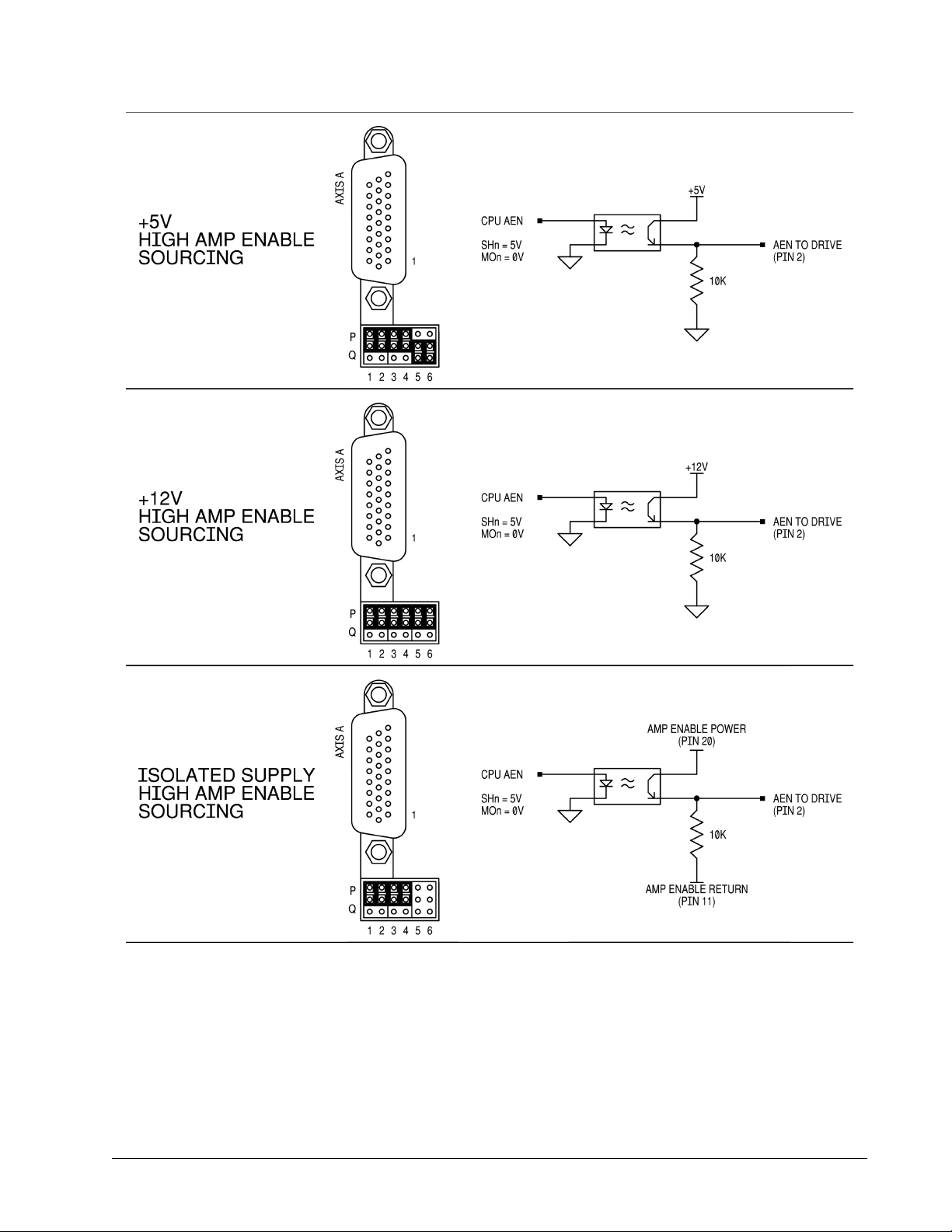
Chapter 3 Connecting Hardware ▫ 48 DMC-40x0 User Manual

Chapter 3 Connecting Hardware ▫ 49 DMC-40x0 User Manual

Chapter 4 Software Tools and
Communication
Introduction
The default configuration DMC-40x0, with the default CMB-41012 communication board, has two RS232 ports and
1 Ethernet port. An additional Ethernet port is available with the CMB-41022. The main RS-232 port is the data set
and can be configured through the jumpers on the top of the controller. The auxiliary RS-232 port is the data term
and can be configured with the software command CC. This configuration can be saved using the Burn (BN)
instruction. The Ethernet port(s) is a 10/100BASE-T connection that auto-negotiates the speed and half or full
duplex.
The GalilTools software package is available for PC computers running Microsoft Windows® to communicate with
the DMC-40x0 controller. This software package has been developed to operate under Windows and Linux, and
include all the necessary drivers to communicate to the controller. In addition, GalilTools includes a software
development communication library which allows users to create their own application interfaces using
programming environments such as C, C++, Visual Basic, and LabVIEW.
The following sections in this chapter are a description of the communications protocol, and a brief introduction to
the software tools and communication techniques used by Galil. At the application level, GalilTools is the basic
programs that the majority of users will need to communicate with the controller, to perform basic setup, and to
develop application code (.dmc programs) that is downloaded to the controller. At the Galil API level, the GalilTools
Communication Library is available for users who wish to develop their own custom application programs to
communicate to the controller. Custom application programs can utilize API function calls directly to our DLL’s. At
the driver level, we provide fundamental hardware interface information for users who desire to create their own
drivers.
Controller Response to Commands
Most DMC-40x0 instructions are represented by two characters followed by the appropriate parameters. Each
instruction must be terminated by a carriage return. Multiple commands may be concatenated by inserting a
semicolon between each command.
Instructions are sent in ASCII, and the DMC-40x0 decodes each ASCII character (one byte) one at a time. It takes
approximately 40 μsec for the controller to decode each command.
After the instruction is decoded, the DMC-40x0 returns a response to the port from which the command was
generated. If the instruction was valid, the controller returns a colon (:) or the controller will respond with a
Chapter 4 Software Tools and Communication ▫ 50 DMC-40x0 User Manual

question mark (?) if the instruction was not valid. For example, the controller will respond to commands which are
sent via the main RS-232 port back through the RS-232 port, and to commands which are sent via the Ethernet port
back through the Ethernet port.
For instructions that return data, such as Tell Position (TP), the DMC-40x0 will return the data followed by a
carriage return, line feed and : .
It is good practice to check for : after each command is sent to prevent errors. An echo function is provided to
enable associating the DMC-40x0 response with the data sent. The echo is enabled by sending the command EO 1
to the controller.
Unsolicited Messages Generated by Controller
When the controller is executing a program, it may generate responses which will be sent via the main RS-232 port
or Ethernet ports. This response could be generated as a result of messages using the MG command OR as a result
of a command error. These responses are known as unsolicited messages since they are not generated as the
direct response to a command.
Messages can be directed to a specific port using the specific Port arguments – see the MG and CF commands in
the Command Reference. If the port is not explicitly given or the default is not changed with the CF command,
unsolicited messages will be sent to the default port. The default port is the main serial port. When
communicating via an Ethernet connection, the unsolicited messages must be sent through a handle that is not the
main communication handle from the host. The GalilTools software automatically establishes this second
communication handle.
The controller has a special command, CW, which can affect the format of unsolicited messages. This command is
used by Galil Software to differentiate response from the command line and unsolicited messages. The command,
CW1 causes the controller to set the high bit of ASCII characters to 1 of all unsolicited characters. This may cause
characters to appear garbled to some terminals. This function can be disabled by issuing the command, CW2. For
more information, see the CW command in the Command Reference.
When handshaking is used (hardware and/or software handshaking) characters which are generated by the
controller are placed in a FIFO buffer before they are sent out of the controller. The size of the RS-232 buffer is 512
bytes. When this buffer becomes full, the controller must either stop executing commands or ignore additional
characters generated for output. The command CW,1 causes the controller to ignore all output from the controller
while the FIFO is full. The command, CW ,0 causes the controller to stop executing new commands until more
room is made available in the FIFO. This command can be very useful when hardware handshaking is being used
and the communication line between controller and terminal will be disconnected. In this case, characters will
continue to build up in the controller until the FIFO is full. For more information, see the CW command in the
Command Reference.
Serial Communication Ports
The RS-232 and RS-422 (optional) are located on the CMB (communication board) of the DMC-40x0. Note that the
auxiliary port is essentially the same as the main port except inputs and outputs are reversed.
RS-232 Configuration
The pin-outs for the RS-232 ports can be found on either A9 – CMB-41012 (-C012), pg 255 or A10 – CMB-41022 (C022), pg 259 depending on the CMB option ordered.
Chapter 4 Software Tools and Communication ▫ 51 DMC-40x0 User Manual

Configure your PC for 8-bit data, one start-bit, one stop-bit, full duplex and no parity. The baud rate for the RS232
communication can be selected by setting the proper switch configuration on the front panel according to the table
below.
Baud Rate Selection
JP1 JUMPER SETTINGS
19.2 38.4
ON ON 9600
ON OFF 19200
OFF ON 38400
OFF OFF 115200
BAUD RATE
Handshaking
The RS232 main port is set for hardware handshaking. Hardware Handshaking uses the RTS and CTS lines. The CTS
line will go high whenever the DMC-40x0 is not ready to receive additional characters. The RTS line will inhibit the
DMC-40x0 from sending additional characters. Note, the RTS line goes high for inhibit.
Auxiliary RS-232 Port Configuration
The main purpose of the auxiliary RS232 port is to connect to external devices that cannot use DMC code to
communicate. It is important to note that the Aux port is not an interpreted port and cannot receive DMC Galil
commands directly. Instead, use CI, #COMINT, and the P2 operands to handle received data on this port.
NOTE: If you are connecting the RS-232 auxiliary port to a terminal or any device which is a DATASET, it is necessary
to use a connector adapter, which changes a dataset to a dataterm. This cable is also known as a 'null' modem
cable.
CC Command
The CC, or Configure Communications command, configures the auxiliary ports properties including: Baud rate,
handshaking, enable/disabled port, and echo. See the CC command in the Command Reference for a full
description and command syntax.
If the CC command is configured for hardware handshaking it is required to use the RTS and CTS lines. The RTS line
will go high whenever the DMC is not ready to receive additional characters. The CTS line will inhibit the DMC from
sending additional characters. Note, the CTS line goes high for inhibit.
RS-422 Configuration
The DMC-40x0 can be ordered with the main and/or auxiliary port configured for RS-422 communication. RS-422
communication is a differentially driven serial communication protocol that should be used when long distance
serial communication is required in an application.
See RS-422 – Serial Port Serial Communication, pg 187 for pin-outs and details of the RS-422 options.
Chapter 4 Software Tools and Communication ▫ 52 DMC-40x0 User Manual

Ethernet Configuration
Communication Protocols
The Ethernet is a local area network through which information is transferred in units known as packets.
Communication protocols are necessary to dictate how these packets are sent and received. The DMC-40x0
supports two industry standard protocols, TCP/IP and UDP/IP. The controller will automatically respond in the
format in which it is contacted.
TCP/IP is a "connection" protocol. The master, or client, connects to the slave, or server, through a series of packet
handshakes in order to begin communicating. Each packet sent is acknowledged when received. If no
acknowledgment is received, the information is assumed lost and is resent.
Unlike TCP/IP, UDP/IP does not require a "connection". If information is lost, the controller does not return a colon
or question mark. Because UDP does not provide for lost information, the sender must re-send the packet.
It is recommended that the motion control network containing the controller and any other related devices be
placed on a “closed” network. If this recommendation is followed, UDP/IP communication to the controller may be
utilized instead of a TCP connection. With UDP there is less overhead, resulting in higher throughput. Also, there is
no need to reconnect to the controller with a UDP connection. Because handshaking is built into the Galil
communication protocol through the use of colon or question mark responses to commands sent to the controller,
the TCP handshaking is not required.
Packets must be limited to 512 data bytes (including UDP/TCP IP Header) or less. Larger packets could cause the
controller to lose communication.
NOTE: In order not to lose information in transit, the user must wait for the controller's response before sending
the next packet.
Addressing
There are three levels of addresses that define Ethernet devices. The first is the MAC or hardware address. This is
a unique and permanent 6 byte number. No other device will have the same MAC address. The DMC-40x0 MAC
address is set by the factory and the last two bytes of the address are the serial number of the board. To find the
Ethernet MAC address for a DMC-40x0 unit, use the TH command. A sample is shown here with a unit that has a
serial number of 3:
Sample MAC Ethernet Address: 00-50-4C-20-04-AF
The second level of addressing is the IP address. This is a 32-bit (or 4 byte) number that usually looks like this:
192.168.15.1. The IP address is constrained by each local network and must be assigned locally. Assigning an IP
address to the DMC-40x0 controller can be done in a number of ways.
The first method for setting the IP address is using a DHCP server. The DH command controls whether the DMC40x0 controller will get an IP address from the DHCP server. If the unit is set to DH1 (default) and there is a DHCP
server on the network, the controller will be dynamically assigned an IP address from the server. Setting the board
to DH0 will prevent the controller from being assigned an IP address from the server.
The second method to assign an IP address is to use the BOOT-P utility via the Ethernet connection. The BOOT-P
functionality is only enabled when DH is set to 0. Either a BOOT-P server on the internal network or the Galil
software may be used. When opening the Galil Software, it will respond with a list of all DMC-40x0’s and other
controllers on the network that do not currently have IP addresses. The user must select the board and the
software will assign the specified IP address to it. This address will be burned into the controller (BN) internally to
save the IP address to the non-volatile memory.
Chapter 4 Software Tools and Communication ▫ 53 DMC-40x0 User Manual

NOTE: if multiple boards are on the network – use the serial numbers to differentiate them.
Be sure that there is only one BOOT-P or DHCP server running. If your network has DHCP
or BOOT-P running, it may automatically assign an IP address to the DMC-40x0 controller
CAUTION
The third method for setting an IP address is to send the IA command through the RS-232 port. (Note: The IA
command is only valid if DH0 is set). The IP address may be entered as a 4 byte number delimited by commas
(industry standard uses periods) or a signed 32 bit number (e.g. IA 124,51,29,31 or IA 2083724575). Type in BN to
save the IP address to the DMC-40x0 non-volatile memory.
NOTE: Galil strongly recommends that the IP address selected is not one that can be accessed across the Gateway.
The Gateway is an application that controls communication between an internal network and the outside world.
The third level of Ethernet addressing is the UDP or TCP port number. The Galil board does not require a specific
port number. The port number is established by the client or master each time it connects to the DMC-40x0 board.
Typical port numbers for applications are:
Port 23: Telnet
Port 502: Modbus
upon linking it to the network. In order to ensure that the IP address is correct, please
contact your system administrator before connecting the I/O board to the Ethernet
network.
Communicating with Multiple Devices
The DMC-40x0 is capable of supporting multiple masters and slaves. The masters may be multiple PC's that send
commands to the controller. The slaves are typically peripheral I/O devices that receive commands from the
controller.
NOTE: The term "Master" is equivalent to the internet "client". The term "Slave" is equivalent to the internet
"server".
An Ethernet handle is a communication resource within a device. The DMC-40x0 can have a maximum of 8
Ethernet handles open at any time. When using TCP/IP, each master or slave uses an individual Ethernet handle. In
UDP/IP, one handle may be used for all the masters, but each slave uses one. (Pings and ARPs do not occupy
handles.) If all 8 handles are in use and a 9th master tries to connect, it will be sent a "reset packet" that generates
the appropriate error in its windows application.
NOTE: There are a number of ways to reset the controller. Hardware reset (push reset button or power down
controller) and software resets (through Ethernet or RS232 by entering RS).
When the Galil controller acts as the master, the IH command is used to assign handles and connect to its slaves.
The IP address may be entered as a 4 byte number separated with commas (industry standard uses periods) or as a
signed 32 bit number. A port number may also be specified, but if it is not, it will default to 1000. The protocol
(TCP/IP or UDP/IP) to use must also be designated at this time. Otherwise, the controller will not connect to the
slave. (Ex. IHB=151,25,255,9<179>2 This will open handle #2 and connect to the IP address 151.25.255.9, port
179, using TCP/IP)
Which devices receive what information from the controller depends on a number of things. If a device queries the
controller, it will receive the response unless it explicitly tells the controller to send it to another device. If the
command that generates a response is part of a downloaded program, the response will route to whichever port is
specified as the default (unless explicitly told to go to another port with the CF command). To designate a specific
destination for the information, add {Eh} to the end of the command. (Ex. MG{EC}"Hello" will send the message
"Hello" to handle #3. TP,,?{EF} will send the z axis position to handle #6.)
Chapter 4 Software Tools and Communication ▫ 54 DMC-40x0 User Manual

Multicasting
A multicast may only be used in UDP/IP and is similar to a broadcast (where everyone on the network gets the
information) but specific to a group. In other words, all devices within a specified group will receive the
information that is sent in a multicast. There can be many multicast groups on a network and are differentiated by
their multicast IP address. To communicate with all the devices in a specific multicast group, the information can
be sent to the multicast IP address rather than to each individual device IP address. All Galil controllers belong to a
default multicast address of 239.255.19.56. The controller's multicast IP address can be changed by using the IA> u
command.
Using Third Party Software
Galil supports DHCP, ARP, BOOT-P, and Ping which are utilities for establishing Ethernet connections. DHCP is a
protocol used by networked devices (clients) to obtain the parameters necessary for operation in an Internet
Protocol network. ARP is an application that determines the Ethernet (hardware) address of a device at a specific
IP address. BOOT-P is an application that determines which devices on the network do not have an IP address and
assigns the IP address you have chosen to it. Ping is used to check the communication between the device at a
specific IP address and the host computer.
The DMC-40x0 can communicate with a host computer through any application that can send TCP/IP or UDP/IP
packets. A good example of this is Telnet, a utility that comes with most Windows systems.
Modbus
An additional protocol layer is available for speaking to I/O devices. Modbus is an RS-485 protocol that packages
information in binary packets that are sent as part of a TCP/IP packet. In this protocol, each slave has a 1 byte slave
address. The DMC-40x0 can use a specific slave address or default to the handle number. The port number for
Modbus is 502. The DMC-40x0 can fill the role of either a Modbus master or Modbus slave.
The Modbus protocol has a set of commands called function codes. The DMC-40x0 supports the 10 major function
codes as a Modbus Master:
Function Code Definition
01 Read Coil Status (Read Bits)
02 Read Input Status (Read Bits)
03 Read Holding Registers (Read Words)
04 Read Input Registers (Read Words)
05 Force Single Coil (Write One Bit)
06 Preset Single Register (Write One Word)
07 Read Exception Status (Read Error Code)
15 Force Multiple Coils (Write Multiple Bits)
16 Preset Multiple Registers (Write Words)
17 Report Slave ID
The DMC-40x0 supports 2 major function codes as a Modbus Slave:
Function Code Definition
03 Read Holding Registers (Read Words)
16 Preset Multiple Registers (Write Words)
A Modbus master has the ability to read and write array data on the DMC-40x0¹ acting as a slave (up to 1000
elements are available). Each element is accessible as a 16-bit unsigned integer (Modbus register 1xxx) or as a 32-
Chapter 4 Software Tools and Communication ▫ 55 DMC-40x0 User Manual

bit floating point number (Modbus registers 2xxx). The ability to write to the slaves array table is enabled by setting
the ME command (ME is not needed to read array data). See the DMC-40x0 Command Reference for further
details.
¹ Only DMC-40x0 firmware revisions Rev 1.2d and later support Modbus slave capability via the ME command.
The DMC-40x0 provides three levels of Modbus communication. The first level allows the user to create a raw
packet and receive raw data. It uses the MBh command with a function code of –1. The format of the command is
MBh = -1,len,array[] where len is the number of bytes
array[] is the array with the data
The second level incorporates the Modbus structure. This is necessary for sending configuration and special
commands to an I/O device. The formats vary depending on the function code that is called. For more information
refer to the Command Reference.
The third level of Modbus communication uses standard Galil commands. Once the slave has been configured, the
commands that may be used are @IN[], @AN[], SB, CB, OB, and AO. For example, AO 2020,8.2 would tell I/O
number 2020 to output 8.2 volts.
If a specific slave address is not necessary, the I/O number to be used can be calculated with the following:
I/O Number = (HandleNum*1000) + ((Module-1)*4) + (BitNum-1)
Where HandleNum is the handle number from 1 (A) to 8 (H). Module is the position of the module in the rack from
1 to 16. BitNum is the I/O point in the module from 1 to 4.
Modbus Examples
Example #1
DMC-4040 connected as a Modbus master to a RIO-47120 via Modbus. The DMC-4040 will set or clear all 16 of the
RIO’s digital outputs
1. Begin by opening a connection to the RIO which in our example has IP address 192.168.1.120
IHB=192,168,1,120<502>2 (Issued to DMC-4040)
2. Dimension an array to store the commanded values. Set array element 0 equal to 170 and array element 1
equal to 85. (array element 1 configures digital outputs 15-8 and array element 0 configures digital
outputs 7-0)
DM myarray[2]
myarray[0] = 170 (which is 10101010 in binary)
myarray[1] = 85 (which is 01010101in binary)
3. a) Send the appropriate MB command. Use function code 15. Start at output 0 and set/clear all 16
outputs based on the data in myarray[]
MBB=,15,0,16,myarray[]
3. b) Set the outputs using the SB command.
SB2001;SB2003;SB2005;SB2007;SB2008;SB2010;SB2012;SB2014;
Results:
Both steps 3a and 3b will result in outputs being activated as below. The only difference being that step 3a will set
and clear all 16 bits where as step 3b will only set the specified bits and will have no affect on the others.
Chapter 4 Software Tools and Communication ▫ 56 DMC-40x0 User Manual

Bit Number Status Bit Number Status
0 0 8 1
1 1 9 0
2 0 10 1
3 1 11 0
4 0 12 1
5 1 13 0
6 0 14 1
7 1 15 0
Example #2
DMC-4040 connected as a Modbus master to a 3rd party PLC. The DMC-4040 will read the value of analog inputs 3
and 4 on the PLC located at addresses 40006 and 40008 respectively. The PLC stores values as 32-bit floating point
numbers which is common.
1. Begin by opening a connection to the PLC which has an IP address of 192.168.1.10 in our example
IHB=192,168,1,10<502>2
2. Dimension an array to store the results
DM myanalog[4]
3. Send the appropriate MB command. Use function code 4 (as specified per the PLC). Start at address
40006. Retrieve 4 modbus registers (2 modbus registers per 1 analog input, as specified by the PLC)
MBB=,4,40006,4,myanalog[]
Results:
Array elements 0 and 1 will make up the 32 bit floating point value for analog input 3 on the PLC and array
elements 2 and 3 will combine for the value of analog input 4.
myanalog[0]=16412=0x401C
myanalog[1]=52429=0xCCCD
myanalog[2]=49347=0xC0C3
myanalog[3]=13107=0x3333
Analog input 3 = 0x401CCCCD = 2.45V
Analog input 4 = 0xC0C33333 = -6.1V
Example #3
DMC-4040 connected as a Modbus master to a hydraulic pump. The DMC-4040 will set the pump pressure by
writing to an analog output on the pump located at Modbus address 30000 and consisting of 2 Modbus registers
forming a 32 bit floating point value.
1. Begin by opening a connection to the pump which has an IP address of 192.168.1.100 in our example
IHB=192,168,1,100<502>2
2. Dimension and fill an array with values that will be written to the PLC
DM pump[2]
pump[0]=16531=0x4093
pump[1]=13107=0x3333
Chapter 4 Software Tools and Communication ▫ 57 DMC-40x0 User Manual

3. Send the appropriate MB command. Use function code 16. Start at address 30000 and write to 2 registers
General Controller Information and Status
ADDR
TYPE
ITEM
ADDR
TYPE
ITEM
00
UB
1st Byte of Header
30-31
SW
Reserved01UB
2nd Byte of Header
32-33
SW
Reserved
02
UB
3rd Byte of Header
34-35
SW
Reserved
03
UB
4th Byte of Header
36-37
SW
Reserved
04-05
UW
sample number
38-39
SW
Reserved06UB
general input block 0 (inputs 1-8)
40-41
SW
Reserved07UB
general input block 1 (inputs 9-16)
42UBEthernet Handle A Status
08
UB
general input block 2 (inputs 17-24)
43UBEthernet Handle B Status
09
UB
general input block 3 (inputs 25-32)
44UBEthernet Handle C Status
10
UB
general input block 4 (inputs 33-40)
45UBEthernet Handle D Status
11
UB
general input block 5 (inputs 41-48)
46UBEthernet Handle E Status
12
UB
general input block 6 (inputs 49-56)
47UBEthernet Handle F Status
13
UB
general input block 7 (inputs 57-64)
48UBEthernet Handle G Status
14
UB
general input block 8 (inputs 65-72)
49UBEthernet Handle H Status
15
UB
general input block 9 (inputs 73-80)
50UBerror code
16
UB
general output block 0 (outputs 1-8)
51UBthread status – see bit field map below
17
UB
general output block 1 (outputs 9-16)
52-55
UL
Amplifier Status
18
UB
general output block 2 (outputs 17-24)
56-59
UL
Segment Count for Contour Mode
19
UB
general output block 3 (outputs 25-32)
60-61
UW
Buffer space remaining – Contour Mode
20
UB
general output block 4 (outputs 33-40)
62-63
UW
segment count of coordinated move for S plane
using the data in the array pump[]
MBB=,16,30000,2,pump[]
Results:
Analog output will be set to 0x40933333 which is 4.6V
Data Record
The DMC-40x0 can provide a binary block of status information with the use of the QR and DR commands. These
commands, along with the QZ command can be very useful for accessing complete controller status. The QR
command will return 4 bytes of header information and specific blocks of information as specified by the command
arguments:
QR ABCDEFGHST
Each argument corresponds to a block of information according to the Data Record Map below. If no argument is
given, the entire data record map will be returned. Note that the data record size will depend on the number of
axes.
Data Record Map Key
Acronym Meaning
UB Unsigned byte
UW Unsigned word
SW Signed word
SL Signed long
UL Unsigned long
21 UB general output block 5 (outputs 41-48) 64-65 UW coordinated move status for S plane – see bit field map
22 UB general output block 6 (outputs 49-56) 66-69 SL distance traveled in coordinated move for S plane
Chapter 4 Software Tools and Communication ▫ 58 DMC-40x0 User Manual
below

23
UB
general output block 7 (outputs 57-64)
70-71
UW
Buffer space remaining – S Plane
24
UB
general output block 8 (outputs 65-72)
72-73
UW
segment count of coordinated move for T plane
25 UB general output block 9 (outputs 73-80) 74-75 UW Coordinated move status for T plane – see bit field map
below
28-29
SW
Reserved
80-81
UW
Buffer space remaining – T Plane
26-27 SW Reserved 76-79 SL distance traveled in coordinated move for T plane
Chapter 4 Software Tools and Communication ▫ 59 DMC-40x0 User Manual

Axis Information
ADDR
TYPE
ITEM
ADDR
TYPE
ITEM
85UBA axis stop code
229UBE axis stop code
86-89SLA axis reference position
230-233
SL
E axis reference position
90-93SLA axis motor position
234-237
SL
E axis motor position
94-97SLA axis position error
238-241
SL
E axis position error
98-101
SL
A axis auxiliary position
242-245
SL
E axis auxiliary position
102-105
SL
A axis velocity
246-249
SL
E axis velocity
106-109
SL
A axis torque
250-253
SL
E axis torque
112UBA Hall Input Status
256UBE Hall Input Status
113UBReserved
257UBReserved
114-117
SL
A User defined variable (ZA)
258-261
SL
E User defined variable (ZE)
121UBB axis stop code
265UBF axis stop code
122-125
SL
B axis reference position
266-269
SL
F axis reference position
126-129
SL
B axis motor position
270-273
SL
F axis motor position
130-133
SL
B axis position error
274-277
SL
F axis position error
134-137
SL
B axis auxiliary position
278-281
SL
F axis auxiliary position
138-141
SL
B axis velocity
282-285
SL
F axis velocity
142-145
SL
B axis torque
286-289
SL
F axis torque
148UBB Hall Input Status
292UBF Hall Input Status
149UBReserved
293UBReserved
150-153
SL
B User defined variable (ZB)
294-297
SL
F User defined variable (ZF)
157UBC axis stop code
301UBG axis stop code
158-161
SL
C axis reference position
302-305
SL
G axis reference position
162-165
SL
C axis motor position
306-309
SL
G axis motor position
166-169
SL
C axis position error
310-313
SL
G axis position error
170-173
SL
C axis auxiliary position
314-317
SL
G axis auxiliary position
174-177
SL
C axis velocity
318-321
SL
G axis velocity
178-181
SL
C axis torque
322-325
SL
G axis torque
184UBC Hall Input Status
328UBG Hall Input Status
185UBReserved
329UBReserved
186-189
SL
C User defined variable (ZC)
330-333
SL
G User defined variable (ZG)
193UBD axis stop code
337UBH axis stop code
194-197
SL
D axis reference position
338-341
SL
H axis reference position
198-201
SL
D axis motor position
342-345
SL
H axis motor position
202-205
SL
D axis position error
346-349
SL
H axis position error
206-209
SL
D axis auxiliary position
350-353
SL
H axis auxiliary position
210-213
SL
D axis velocity
354-357
SL
H axis velocity
214-217
SL
D axis torque
358-361
SL
H axis torque
220UBD Hall Input Status
364UBH Hall Input Status
82-83 UW A axis status – see bit field map below 226-227 UW E axis status – see bit field map below
84 UB A axis switches – see bit field map below 228 UB E axis switches – see bit field map below
110-111 SW or UW 1A axis analog input 254-255 SW or UW 1E axis analog input
118-119 UW B axis status – see bit field map below 262-263 UW F axis status – see bit field map below
120 UB B axis switches – see bit field map below 264 UB F axis switches – see bit field map below
146-147 SW or UW 1B axis analog input 290-291 SW or UW 1F axis analog input
154-155 UW C axis status – see bit field map below 298-299 UW G axis status – see bit field map below
156 UB C axis switches – see bit field map below 300 UB G axis switches – see bit field map below
182-183 SW or UW 1C axis analog input 326-327 SW or UW 1G axis analog input
190-191 UW D axis status – see bit field map below 334-335 UW H axis status – see bit field map below
192 UB D axis switches – see bit field map below 336 UB H axis switches – see bit field map below
218-219 SW or UW 1D axis analog input 362-363 SW or UW 1H axis analog input
Chapter 4 Software Tools and Communication ▫ 60 DMC-40x0 User Manual

221UBReserved
365UBReserved
222-225
SL
D User defined variable (ZD)
366-369
SL
H User defined variable (ZH)
1
Will be either a Signed Word or Unsigned Word depending upon AQ setting. See AQ in the Command Reference for more information.
Chapter 4 Software Tools and Communication ▫ 61 DMC-40x0 User Manual
Data Record Bit Field Maps
Header Information - Byte 0, 1 of Header:
BIT 15 BIT 14 BIT 13 BIT 12 BIT 11 BIT 10 BIT 9 BIT 8
1 N/A N/A N/A N/A
I Block Present
in Data Record
BIT 7 BIT 6 BIT 5 BIT 4 BIT 3 BIT 2 BIT 1 BIT 0
H Block Present
in Data Record
G Block Present
in Data Record
F Block Present
in Data Record
E Block Present
in Data Record
D Block Present
in Data Record
C Block Present
in Data Record
Bytes 2, 3 of Header:
Bytes 2 and 3 make a word which represents the Number of bytes in the data record, including the header.
Byte 2 is the low byte and byte 3 is the high byte
NOTE: The header information of the data records is formatted in little endian (reversed network byte order).
Thread Status (1 Byte)
BIT 7 BIT 6 BIT 5 BIT 4 BIT 3 BIT 2 BIT 1 BIT 0
Thread 7
Running
Thread 6
Running
Thread 5
Running
Thread 4
Running
Thread 3
Running
Thread 2
Running
Coordinated Motion Status for S or T Plane (2 Byte)
BIT 15 BIT 14 BIT 13 BIT 12 BIT 11 BIT 10 BIT 9 BIT 8
Move in
Progress
N/A N/A N/A N/A N/A N/A N/A
T Block Present
in Data Record
B Block Present
in Data Record
Thread 1
Running
S Block Present
in Data Record
A Block Present
in Data Record
Thread 0
Running
BIT 7 BIT 6 BIT 5 BIT 4 BIT 3 BIT 2 BIT 1 BIT 0
N/A N/A
Motion is
slewing
Motion is
stopping due to
ST or Limit
Switch
Motion is
making final
deceleration
N/A N/A N/A
Axis Status (1 Word)
BIT 15 BIT 14 BIT 13 BIT 12 BIT 11 BIT 10 BIT 9 BIT 8
Move in
Progress
Mode of
Motion PA or PR
Mode of
Motion PA only
(FE) Find Edge
in Progress
Home (HM) in
Progress
1st Phase of HM
complete
2nd Phase of HM
complete or FI
command
issued
BIT 7 BIT 6 BIT 5 BIT 4 BIT 3 BIT 2 BIT 1 BIT 0
Negative
Direction Move
Mode of
Motion
Contour
Motion is
slewing
Motion is
stopping due to
ST of Limit
Switch
Motion is
making final
deceleration
Latch is armed
3rd Phase of
HM in Progress
Axis Switches (1 Byte)
BIT 7 BIT 6 BIT 5 BIT 4 BIT 3 BIT 2 BIT 1 BIT 0
Latch Occurred
State of Latch
Input
N/A N/A
State of
Forward Limit
State of Reverse
Limit
State of Home
Input
Mode of
Motion Coord.
Motion
Motor Off
Stepper Mode
Chapter 4 Software Tools and Communication ▫ 62 DMC-40x0 User Manual

Amplifier Status (4 Bytes)
BIT 31 BIT 30 BIT 29 BIT 28 BIT 27 BIT 26 BIT 25 BIT 24
N/A N/A N/A N/A N/A N/A
ELO Active
(Axis E-H)
ELO Active
(Axis A-D)
BIT 23 BIT 22 BIT 21 BIT 20 BIT 19 BIT 18 BIT 17 BIT 16
Peak Current
H-axis
Peak Current
G-axis
Peak Current
F-axis
Peak Current
E-axis
Peak Current
D-axis
Peak Current
C-axis
Peak Current
B-axis
Peak current
A-axis
BIT 15 BIT 14 BIT 13 BIT 12 BIT 11 BIT 10 BIT 9 BIT 8
Hall Error
H-axis
Hall Error
G-axis
Hall Error
F-axis
Hall Error
E-axis
Hall Error
D-axis
Hall Error
C-axis
Hall Error
B-axis
Hall Error
A-axis
BIT 7 BIT 6 BIT 5 BIT 4 BIT 3 BIT 2 BIT 1 BIT 0
Under Voltage
Axis (E-H)
Over Temp.
Axis (E-H)
Over Voltage
Axis (E-H)
Over Current
Axis (E-H)
Under Voltage
Axis (A-D)
Over Temp.
Axis (A-D)
Over Voltage
Axis (A-D)
Over Current
Axis (A-D)
Notes Regarding Velocity and Torque Information
The velocity information that is returned in the data record is 64 times larger than the value returned when using
the command TV (Tell Velocity). See command reference for more information about TV.
The Torque information is represented as a number in the range of ±32767. Maximum negative torque is -32767.
Maximum positive torque is 32767. Zero torque is 0.
QZ Command
The QZ command can be very useful when using the QR command, since it provides information about the
controller and the data record. The QZ command returns the following 4 bytes of information.
BYTE # INFORMATION
0 Number of axes present
1 number of bytes in general block of data record
2 number of bytes in coordinate plane block of data record
3 Number of Bytes in each axis block of data record
Chapter 4 Software Tools and Communication ▫ 63 DMC-40x0 User Manual

GalilSuite (Windows and Linux)
GalilSuite is Galil's latest set of development tools for the latest generation of Galil controllers. It is highly
recommended for all first-time purchases of Galil controllers as it provides easy set-up, tuning and analysis.
GalilSuite replaces GalilToolS with an improved user-interface, real-time scopes, advanced tuning methods, and
communications utilities.
Supported Controllers
•DMC40x0
•DMC41x3
•DMC30010
•DMC21x3/2
•RIO47xxx
•DMC18x6 - PCI Driver required, separate installer
•DMC18x0 - PCI Driver required, separate installer
•DMC18x2* - PCI Driver required, separate installer
Contact Galil for other hardware products
Supported Operating Systems**
•Microsoft Windows 8
•Microsoft Windows 7
•Microsoft Windows XP SP3
•Scope, Watch, and Viewer support require an Ethernet or PCI connection and controller firmware
supporting the DR command
* No Scope, Watch, or Viewer support.
** Contact Galil for other OS options.
The GalilSuitecontains the following tools:
Tool Description
Launcher Launcher Tool with the ability to create custom profiles to manage controller connections
Terminal For sending and receiving Galil commands
Editor To easily create and work on multiple Galil programs simultaneously
Viewer To see a complete status of all controllers on a single screen
Scope For viewing and manipulating data for multiple controllers real-time
Watch For simplified debugging of any controller on the system and a display of I/O and motion status
Tuner With up to four methods for automatic and manual PID tuning of servo systems
Configuration For modifying controller settings, backup/restore and firmware download
The latest version of GalilSuite can be downloaded here:
http://www.galilmc.com/support/software-downloads.php
For information on using GalilSuite see the user manual:
http://www.galilmc.com/support/manuals.php
Chapter 4 Software Tools and Communication ▫ 64 DMC-40x0 User Manual

Creating Custom Software Interfaces
Galil provides programming tools so that users can develop their own custom software interfaces to a Galil
controller. For new applications, Galil recommends the GalilTools Communication Libraries.
HelloGalil – Quick Start to PC programming
For programmers developing Windows applications that communicate with a Galil controller, the HelloGalil library
of quick start projects immediately gets you communicating with the controller from the programming language of
your choice. In the "Hello World" tradition, each project contains the bare minimum code to demonstrate
communication to the controller and simply prints the controller's model and serial numbers to the screen Figure
4.1.
Figure 4.1: Sample program output
http://www.galilmc.com/support/hello_galil.html
Galil Communication Libraries
The Galil Communication Library (Galil class) provides methods for communication with a Galil motion controller
over Ethernet, RS-232 or PCI buses. It consists of a native C++ Library and a similar COM interface which extends
compatibility to Windows programming languages (e.g. VB, C#, etc).
A Galil object (usually referred to in sample code as "g") represents a single connection to a Galil controller.
For Ethernet controllers, which support more than one connection, multiple objects may be used to communicate
with the controller. An example of multiple objects is one Galil object containing a TCP handle to a DMC-40x0 for
commands and responses, and one Galil object containing a UDP handle for unsolicited messages from the
controller. If recordsStart() is used to begin the automatic data record function, the library will open an additional
UDP handle to the controller (transparent to the user).
The library is conceptually divided into six categories:
1. Connecting and Disconnecting - functions to establish and discontinue communication with a controller.
2. Basic Communication - The most heavily used functions for command-and-response and unsolicited
messages.
3. Programs - Downloading and uploading embedded programs.
4. Arrays - Downloading and uploading array data.
5. Advanced - Lesser-used calls.
6. Data Record - Access to the data record in both synchronous and asynchronous modes.
Chapter 4 Software Tools and Communication ▫ 65 DMC-40x0 User Manual

C++ Library (Windows and Linux)
Both Full and Lite versions of GalilTools ship with a native C++ communication library. The Linux version (libGalil.so)
is compatible with g++ and the Windows version (Galil1.dll) with Visual C++ 2008. Contact Galil if another version
of the C++ library is required. See the getting started guide and the hello.cpp example in /lib.
COM (Windows)
To further extend the language compatibility on Windows, a COM (Component Object Model) class built on top of
the C++ library is also provided with Windows releases. This COM wrapper can be used in any language and IDE
supporting COM (Visual Studio 2005, 2008, etc). The COM wrapper includes all of the functionality of the base C++
class. See the getting started guide and the hello.* examples in \lib for more info.
For more information on the GalilTools Communications Library, see the online user manual.
http://www.galilmc.com/support/manuals/galiltools/library.html
Chapter 4 Software Tools and Communication ▫ 66 DMC-40x0 User Manual

Chapter 5 Command Basics
Introduction
The DMC-40x0 provides over 100 commands for specifying motion and machine parameters. Commands are
included to initiate action, interrogate status and configure the digital filter. These commands are sent in ASCII.
The DMC-40x0 instruction set is BASIC-like and easy to use. Instructions consist of two uppercase letters that
correspond phonetically with the appropriate function. For example, the instruction BG begins motion, and ST
stops the motion.
Commands can be sent "live" over the communications port for immediate execution by the DMC-40x0, or an
entire group of commands can be downloaded into the DMC-40x0 memory for execution at a later time.
Combining commands into groups for later execution is referred to as Applications Programming and is discussed in
the following chapter.
This section describes the DMC-40x0 instruction set and syntax. A summary of commands as well as a complete
listing of all DMC-40x0 instructions is included in the Command Reference.
Command Syntax - ASCII
DMC-40x0 instructions are represented by two ASCII upper case characters followed by applicable arguments. A
space may be inserted between the instruction and arguments. A semicolon or <return> is used to terminate the
instruction for processing by the DMC-40x0 command interpreter.
NOTE: If you are using a Galil terminal program, commands will not be processed until an <return> command is
given. This allows the user to separate many commands on a single line and not begin execution until the user
gives the <return> command.
NOTE
For example, the command
PR 4000 <return> Position relative
Implicit Notation
PR is the two character instruction for position relative. 4000 is the argument which represents the required
position value in counts. The <return> terminates the instruction. The space between PR and 4000 is optional.
Chapter 5 Command Basics ▫ 67 DMC-40x0 User Manual
All DMC commands are two-letters sent in upper case!

For specifying data for the A,B,C and D axes, commas are used to separate the axes. If no data is specified for an
4080
axis, a comma is still needed as shown in the examples below. If no data is specified for an axis, the previous value
is maintained.
To view the current values for each command, type the command followed by a ? for each axis requested.
PR 1000
PR ,2000
PR ,,3000
PR ,,,4000
PR 2000, 4000,6000, 8000
PR ,8000,,9000
PR ?,?,?,?
PR ,?
Specify A only as 1000
Specify B only as 2000
Specify C only as 3000
Specify D only as 4000
Specify A,B,C and D
Specify B and D only
Request A,B,C,D values
Request B value only
Explicit Notation
The DMC-40x0 provides an alternative method for specifying data. Here data is specified individually using a single
axis specifier such as A, B, C or D. An equals sign is used to assign data to that axis. For example:
Instead of data, some commands request action to occur on an axis or group of axes. For example, ST AB stops
motion on both the A and B axes. Commas are not required in this case since the particular axis is specified by the
appropriate letter A, B, C or D. If no parameters follow the instruction, action will take place on all axes. Here are
some examples of syntax for requesting action:
PRA=1000
ACB=200000
BG A
BG B
BG ABCD
BG BD
BG
Specify a position relative movement for the A axis of 1000
Specify acceleration for the B axis as 200000
Begin A only
Begin B only
Begin all axes
Begin B and D only
Begin all axes
For controllers with 5 or more axes, the axes are referred to as A,B,C,D,E,F,G,H. The specifiers X,Y,Z,W
and A,B,C,D may be used interchangeably.
BG ABCDEFGH
BG D
Begin all axes
Begin D only
Coordinated Motion with more than 1 axis
When requesting action for coordinated motion, the letter S or T is used to specify the coordinated motion. This
allows for coordinated motion to be setup for two separate coordinate systems. Refer to the CA command in the
Command Reference for more information on specifying a coordinate system. For example:
BG S
BG TD
Begin coordinated sequence, S
Begin coordinated sequence, T, and D axis
Controller Response to DATA
The DMC-40x0 returns a : for valid commands and a ? for invalid commands.
For example, if the command BG is sent in lower case, the DMC-40x0 will return a ?.
:bg
?
When the controller receives an invalid command the user can request the error code. The error code will specify
the reason for the invalid command response. To request the error code type the command TC1. For example:
invalid command, lower case
DMC-40x0 returns a ?
Chapter 5 Command Basics ▫ 68 DMC-40x0 User Manual

?TC1
1 Unrecognized command
Tell Code command
Returned response
There are many reasons for receiving an invalid command response. The most common reasons are: unrecognized
command (such as typographical entry or lower case), command given at improper time (such as during motion),
or a command out of range (such as exceeding maximum speed). A complete listing of all codes is listed in the TC
command in the Command Reference section.
Interrogating the Controller
Interrogation Commands
The DMC-40x0 has a set of commands that directly interrogate the controller. When the command is entered, the
requested data is returned in decimal format on the next line followed by a carriage return and line feed. The
format of the returned data can be changed using the Position Format (PF), Variable Format (VF) and Leading Zeros
(LZ) command. See Chapter 7 Application Programming and the Command Reference.
Summary of Interrogation Commands
RP
RL
^R^V
SC
TA
TB
TC
TD
TE
TI
TP
TR
TS
TT
TV
Report Command Position
Report Latch
Firmware Revision Information
Stop Code
Tell Amplifier Error
Tell Status
Tell Error Code
Tell Dual Encoder
Tell Error
Tell Input
Tell Position
Trace
Tell Switches
Tell Torque
Tell Velocity
For example, the following example illustrates how to display the current position of the X axis:
TP A
0
TP AB
0,0
Tell position A
Controllers Response
Tell position A and B
Controllers Response
Interrogating Current Commanded Values.
Most commands can be interrogated by using a question mark (?) as the axis specifier. Type the command
followed by a ? for each axis requested.
PR ?,?,?,?
PR ,?
The controller can also be interrogated with operands.
Chapter 5 Command Basics ▫ 69 DMC-40x0 User Manual
Request A,B,C,D values
Request B value only

Operands
Most DMC-40x0 commands have corresponding operands that can be used for interrogation. Operands must be
used inside of valid DMC expressions. For example, to display the value of an operand, the user could use the
command:
MG ‘operand’ where ‘operand’ is a valid DMC operand
All of the command operands begin with the underscore character (_). For example, the value of the current
position on the A axis can be assigned to the variable ‘V’ with the command:
V=_TPA
The Command Reference denotes all commands which have an equivalent operand as "Operand Usage". Also, see
description of operands in Chapter 7 Application Programming.
Command Summary
For a complete command summary, see Command Reference manual.
http://www.galilmc.com/support/manuals.php
Chapter 5 Command Basics ▫ 70 DMC-40x0 User Manual

Chapter 6 Programming Motion
4080
Overview
The DMC-40x0 provides several modes of motion, including independent positioning and jogging, coordinated
motion, electronic cam motion, and electronic gearing. Each one of these modes is discussed in the following
sections.
The DMC-4010 are single axis controllers and use X-axis motion only. Likewise, the DMC-4020 use X and Y, the
DMC-4030 use X,Y, and Z, and the DMC-4040 use X,Y,Z, and W. The DMC-4050 use A,B,C,D, and E. The DMC-4060
use A,B,C,D,E, and F. The DMC-4070 use A,B,C,D,E,F, and G. The DMC-4080 use the axes A,B,C,D,E,F,G, and H.
The example applications described below will help guide you to the appropriate mode of motion.
For controllers with 5 or more axes, the specifiers, ABCDEFGH, are used. XYZ and W may be interchanged
with ABCD.
EXAMPLE APPLICATION MODE OF MOTION COMMANDS
Absolute or relative positioning where each
axis is independent and follows prescribed
velocity profile.
Velocity control where no final endpoint is
prescribed. Motion stops on Stop command.
Absolute positioning mode where absolute
position targets may be sent to the controller
while the axis is in motion.
Motion Path described as incremental position
points versus time.
Motion Path described as incremental
position, velocity and delta time
2 to 8 axis coordinated motion where path is
described by linear segments.
2-D motion path consisting of arc segments
and linear segments, such as engraving or
quilting.
Third axis must remain tangent to 2-D motion
path, such as knife cutting.
Electronic gearing where slave axes are scaled
to master axis which can move in both
directions.
Master/slave where slave axes must follow a
master such as conveyer speed.
Independent Axis Positioning
Independent Jogging
Position Tracking
Contour Mode
PVT Mode
Linear Interpolation Mode
Vector Mode: Linear and Circular Interpolation
Motion
Coordinated motion with Tangent Motion:
Electronic Gearing
Electronic Gearingwith Ramped Gearing
PA, PR, SP, AC, DC
JG, AC, DC, ST
PA, AC, DC, SP, PT
CM, CD, DT
PV, BT
LM, LI, LE, VS,VR,
VA, VD
VM, VP, CR, VS,VR,
VA, VD, VE
VM, VP, CR, VS,VA,VD,
TN, VE
GA, GD, _GP, GR, GM
(if gantry)
GA, GD, _GP, GR
Chapter 6 Programming Motion ▫ 71 DMC-40x0 User Manual

Moving along arbitrary profiles or
mathematically prescribed profiles such as
sine or cosine trajectories.
Teaching or Record and Play Back Contour Mode with Teach (Record and Play-
Backlash Correction Dual Loop (Auxiliary Encoder)
Following a trajectory based on a master
encoder position
Smooth motion while operating in
independent axis positioning
Smooth motion while operating in vector or
linear interpolation positioning
Smooth motion while operating with stepper
motors
Gantry - two axes are coupled by gantry Example - Gantry Mode
Contour Mode
Back)
Electronic Cam
Independent Motion Smoothing
Motion Smoothing
Using the KS Command (Step Motor Smoothing):
CM, CD, DT
CM, CD, DT, RA, RD,
RC
DV
EA, EM, EP, ET, EB,
EG, EQ
IT
IT
KS
GR, GM
Independent Axis Positioning
In this mode, motion between the specified axes is independent, and each axis follows its own profile. The user
specifies the desired absolute position (PA) or relative position (PR), slew speed (SP), acceleration ramp (AC), and
deceleration ramp (DC), for each axis. On begin (BG), the DMC-40x0 profiler generates the corresponding
trapezoidal or triangular velocity profile and position trajectory. The controller determines a new command
position along the trajectory every sample period until the specified profile is complete. Motion is complete when
the last position command is sent by the DMC-40x0 profiler. Note: The actual motor motion may not be complete
when the profile has been completed, however, the next motion command may be specified.
The Begin (BG) command can be issued for all axes either simultaneously or independently. XYZ or W axis
specifiers are required to select the axes for motion. When no axes are specified, this causes motion to begin on all
axes.
The speed (SP) and the acceleration (AC) can be changed at any time during motion, however, the deceleration
(DC) and position (PR or PA) cannot be changed until motion is complete. Remember, motion is complete when the
profiler is finished, not when the actual motor is in position. The Stop command (ST) can be issued at any time to
decelerate the motor to a stop before it reaches its final position.
An incremental position movement (IP) may be specified during motion as long as the additional move is in the
same direction. Here, the user specifies the desired position increment, n. The new target is equal to the old
target plus the increment, n. Upon receiving the IP command, a revised profile will be generated for motion
towards the new end position. The IP command does not require a begin. Note: If the motor is not moving, the IP
command is equivalent to the PR and BG command combination.
Command Summary - Independent Axis
COMMAND DESCRIPTION
PR x,y,z,w
PA x,y,z,w
SP x,y,z,w
AC x,y,z,w
DC x,y,z,w
BG XYZW
ST XYZW
IP x,y,z,w
IT x,y,z,w
AM XYZW
MC XYZW
Specifies relative distance
Specifies absolute position
Specifies slew speed
Specifies acceleration rate
Specifies deceleration rate
Starts motion
Stops motion before end of move
Changes position target
Time constant for independent motion smoothing
Trippoint for profiler complete
Trippoint for “in position”
Chapter 6 Programming Motion ▫ 72 DMC-40x0 User Manual

The lower case specifiers (x,y,z,w) represent position values for each axis.
The DMC-40x0 also allows use of single axis specifiers such as PRY=2000
Operand Summary - Independent Axis
OPERAND DESCRIPTION
_ACx
_DCx
_SPx
_PAx
_PRx
Example - Absolute Position Movement
PA 10000,20000
AC 1000000,1000000
DC 1000000,1000000
SP 50000,30000
BG XY
Example - Multiple Move Sequence
Required Motion Profiles:
X-Axis 500 counts Position
Return acceleration rate for the axis specified by ‘x’
Return deceleration rate for the axis specified by ‘x’
Returns the speed for the axis specified by ‘x’
Returns current destination if ‘x’ axis is moving, otherwise returns the current commanded
position if in a move.
Returns current incremental distance specified for the ‘x’ axis
Specify absolute X,Y position
Acceleration for X,Y
Deceleration for X,Y
Speeds for X,Y
Begin motion
20000 count/sec Speed
500000 counts/sec
2 Acceleration
Y-Axis 1000 counts Position
10000 count/sec Speed
500000 counts/sec
2 Acceleration
Z-Axis 100 counts Position
5000 counts/sec Speed
500000 counts/sec Acceleration
This example will specify a relative position movement on X, Y and Z axes. The movement on each axis will be
separated by 20 msec. Figure 6.1 shows the velocity profiles for the X,Y and Z axis.
#A
PR 2000,500,100
SP 20000,10000,5000
AC 500000,500000,500000
DC 500000,500000,500000
BG X
WT 20
BG Y
WT 20
BG Z
EN
Begin Program
Specify relative position movement of 2000, 500 and 100 counts for X,Y and Z axes.
Specify speed of 20000, 10000, and 5000 counts / sec
Specify acceleration of 500000 counts / sec2 for all axes
Specify deceleration of 500000 counts / sec2 for all axes
Begin motion on the X axis
Wait 20 msec
Begin motion on the Y axis
Wait 20 msec
Begin motion on Z axis
End Program
Chapter 6 Programming Motion ▫ 73 DMC-40x0 User Manual

Figure 6.1: Velocity Profiles of XYZ
VELOCITY
(COUNTS/SEC)
20000
10000
5000
15000
20
40 60
80
TIME (ms)
100
X axis velocity profile
Y axis velocity profile
Z axis velocity profile
0
Notes on Figure 6.1: The X and Y axis have a ‘trapezoidal’ velocity profile, while the Z axis has a ‘triangular’ velocity
profile. The X and Y axes accelerate to the specified speed, move at this constant speed, and then decelerate such
that the final position agrees with the command position, PR. The Z axis accelerates, but before the specified
speed is achieved, must begin deceleration such that the axis will stop at the commanded position. All 3 axes have
the same acceleration and deceleration rate, hence, the slope of the rising and falling edges of all 3 velocity profiles
are the same.
Independent Jogging
The jog mode of motion is very flexible because speed, direction and acceleration can be changed during motion.
The user specifies the jog speed (JG), acceleration (AC), and the deceleration (DC) rate for each axis. The direction
of motion is specified by the sign of the JG parameters. When the begin command is given (BG), the motor
accelerates up to speed and continues to jog at that speed until a new speed or stop (ST) command is issued. If the
jog speed is changed during motion, the controller will make a accelerated (or decelerated) change to the new
speed.
An instant change to the motor position can be made with the use of the IP command. Upon receiving this
command, the controller commands the motor to a position which is equal to the specified increment plus the
current position. This command is useful when trying to synchronize the position of two motors while they are
moving.
Note that the controller operates as a closed-loop position controller while in the jog mode. The DMC-40x0
converts the velocity profile into a position trajectory and a new position target is generated every sample period.
This method of control results in precise speed regulation with phase lock accuracy.
Command Summary - Jogging
COMMAND DESCRIPTION
AC x,y,z,w
BG XYZW
DC x,y,z,w
IP x,y,z,w
IT x,y,z,w
JG ±x,y,z,w
ST XYZW
Parameters can be set with individual axes specifiers such as JGY=2000 (set jog speed for Y axis to 2000).
Chapter 6 Programming Motion ▫ 74 DMC-40x0 User Manual
Specifies acceleration rate
Begins motion
Specifies deceleration rate
Increments position instantly
Time constant for independent motion smoothing
Specifies jog speed and direction
Stops motion

Operand Summary - Independent Axis
OPERAND DESCRIPTION
_ACx
_DCx
_SPx
_TVx
Example - Jog in X only
Jog X motor at 50000 count/s. After X motor is at its jog speed, begin jogging Z in reverse direction at 25000
count/s.
#A
AC 20000,,20000
DC 20000,,20000
JG 50000,,-25000
BG X
AS X
BG Z
EN
Example - Joystick Jogging
The jog speed can also be changed using an analog input such as a joystick. Assume that for a 10 Volt input the
speed must be 50000 counts/sec.
#JOY
JG0
BGX
#B
V1 =@AN[1]
VEL=V1*50000/10
JG VEL
JP #B
Return acceleration rate for the axis specified by ‘x’
Return deceleration rate for the axis specified by ‘x’
Returns the jog speed for the axis specified by ‘x’
Returns the actual velocity of the axis specified by ‘x’ (averaged over 0.25 sec)
Specify X,Z acceleration of 20000 counts / sec
Specify X,Z deceleration of 20000 counts / sec
Specify jog speed and direction for X and Z axis
Begin X motion
Wait until X is at speed
Begin Z motion
Label
Set in Jog Mode
Begin motion
Label for loop
Read analog input
Compute speed
Change JG speed
Loop
Position Tracking
The Galil controller may be placed in the position tracking mode to support changing the target of an absolute
position move on the fly. New targets may be given in the same direction or the opposite direction of the current
position target. The controller will then calculate a new trajectory based upon the new target and the acceleration,
deceleration, and speed parameters that have been set. The motion profile in this mode is trapezoidal. There is
not a set limit governing the rate at which the end point may be changed, however at the standard TM rate, the
controller updates the position information at the rate of 1msec. The controller generates a profiled point every
other sample, and linearly interpolates one sample between each profiled point. Some examples of applications
that may use this mode are satellite tracking, missile tracking, random pattern polishing of mirrors or lenses, or any
application that requires the ability to change the endpoint without completing the previous move.
The PA command is typically used to command an axis or multiple axes to a specific absolute position. For some
applications such as tracking an object, the controller must proceed towards a target and have the ability to change
the target during the move. In a tracking application, this could occur at any time during the move or at regularly
scheduled intervals. For example if a robot was designed to follow a moving object at a specified distance and the
path of the object wasn’t known the robot would be required to constantly monitor the motion of the object that it
was following. To remain within a specified distance it would also need to constantly update the position target it
is moving towards. Galil motion controllers support this type of motion with the position tracking mode. This
mode will allow scheduled or random updates to the current position target on the fly. Based on the new target
the controller will either continue in the direction it is heading, change the direction it is moving, or decelerate to a
stop.
Chapter 6 Programming Motion ▫ 75 DMC-40x0 User Manual

The position tracking mode shouldn’t be confused with the contour mode. The contour mode allows the user to
generate custom profiles by updating the reference position at a specific time rate. In this mode, the position can
be updated randomly or at a fixed time rate, but the velocity profile will always be trapezoidal with the parameters
specified by AC, DC, and SP. Updating the position target at a specific rate will not allow the user to create a
custom profile.
The following example will demonstrate the possible different motions that may be commanded by the controller
in the position tracking mode. In this example, there is a host program that will generate the absolute position
targets. The absolute target is determined based on the current information the host program has gathered on the
object that it is tracking. The position tracking mode does allow for all of the axes on the controller to be in this
mode, but for the sake of discussion, it is assumed that the robot is tracking only in the X dimension.
The controller must be placed in the position tracking mode to allow on the fly absolute position changes. This is
performed with the PT command. To place the X axis in this mode, the host would issue PT1 to the controller if
both X and Y axes were desired the command would be PT 1,1. The next step is to begin issuing PA command to
the controller. The BG command isn’t required in this mode, the SP, AC, and DC commands determine the shape of
the trapezoidal velocity profile that the controller will use.
Example - Motion 1:
The host program determines that the first target for the controller to move to is located at 5000 encoder counts.
The acceleration and deceleration should be set to 150,000 counts/sec2 and the velocity is set to 50,000
counts/sec. The command sequence to perform this is listed below.
#EX1
PT 1;' Place the X axis in Position tracking mode
AC 150000;' Set the X axis acceleration to 150000 counts/sec2
DC 150000;' Set the X axis deceleration to 150000 counts/sec2
SP 50000;' Set the X axis speed to 50000 counts/sec
PA 5000;' Command the X axis to absolute position 5000 encoder counts
EN
The output from this code can be seen in Figure 6.2, a screen capture from the GalilTools scope.
Figure 6.2: Position vs Time (msec) - Motion 1
Example - Motion 2:
The previous step showed the plot if the motion continued all the way to 5000, however partway through the
motion, the object that was being tracked changed direction, so the host program determined that the actual
target position should be 2000 counts at that time. Figure 6.2 shows what the position profile would look like if the
move was allowed to complete to 5000 counts. The position was modified when the robot was at a position of
4200 counts (Figure 6.3). Note that the robot actually travels to a distance of almost 5000 counts before it turns
around. This is a function of the deceleration rate set by the DC command. When a direction change is
Chapter 6 Programming Motion ▫ 76 DMC-40x0 User Manual

commanded, the controller decelerates at the rate specified by the DC command. The controller then ramps the
velocity in up to the value set with SP in the opposite direction traveling to the new specified absolute position.
Figure 6.3 the velocity profile is triangular because the controller doesn’t have sufficient time to reach the set
speed of 50000 counts/sec before it is commanded to change direction.
The below code is used to simulate this scenario:
#EX2
PT 1;' Place the X axis in Position tracking mode
AC 150000;' Set the X axis acceleration to 150000 counts/sec2
DC 150000;' Set the X axis deceleration to 150000 counts/sec2
SP 50000;' Set the X axis speed to 50000 counts/sec
PA 5000;' Command the X axis to abs position 5000 encoder counts
MF 4200
PA 2000;' Change end point position to position 2000
EN
Figure 6.3: Position and Velocity vs Time (msec) for Motion 2
Example - Motion 3:
In this motion, the host program commands the controller to begin motion towards position 5000, changes the
target to -2000, and then changes it again to 8000. Figure 6.4 shows the plot of position vs. time and velocity vs.
time. Below is the code that is used to simulate this scenario:
#EX3
PT 1;' Place the X axis in Position tracking mode
AC 150000;' Set the X axis acceleration to 150000 counts/sec2
DC 150000;' Set the X axis deceleration to 150000 counts/sec2
SP 50000;' Set the X axis speed to 50000 counts/sec
PA 5000;' Command the X axis to abs position 5000 encoder counts
WT 300
PA -2000;' Change end point position to -2000
WT 200
PA 8000;' Change end point position to 8000
EN
Figure 6.5 demonstrates the use of motion smoothing (IT) on the velocity profile in this mode. The jerk in the
system is also affected by the values set for AC and DC.
Chapter 6 Programming Motion ▫ 77 DMC-40x0 User Manual
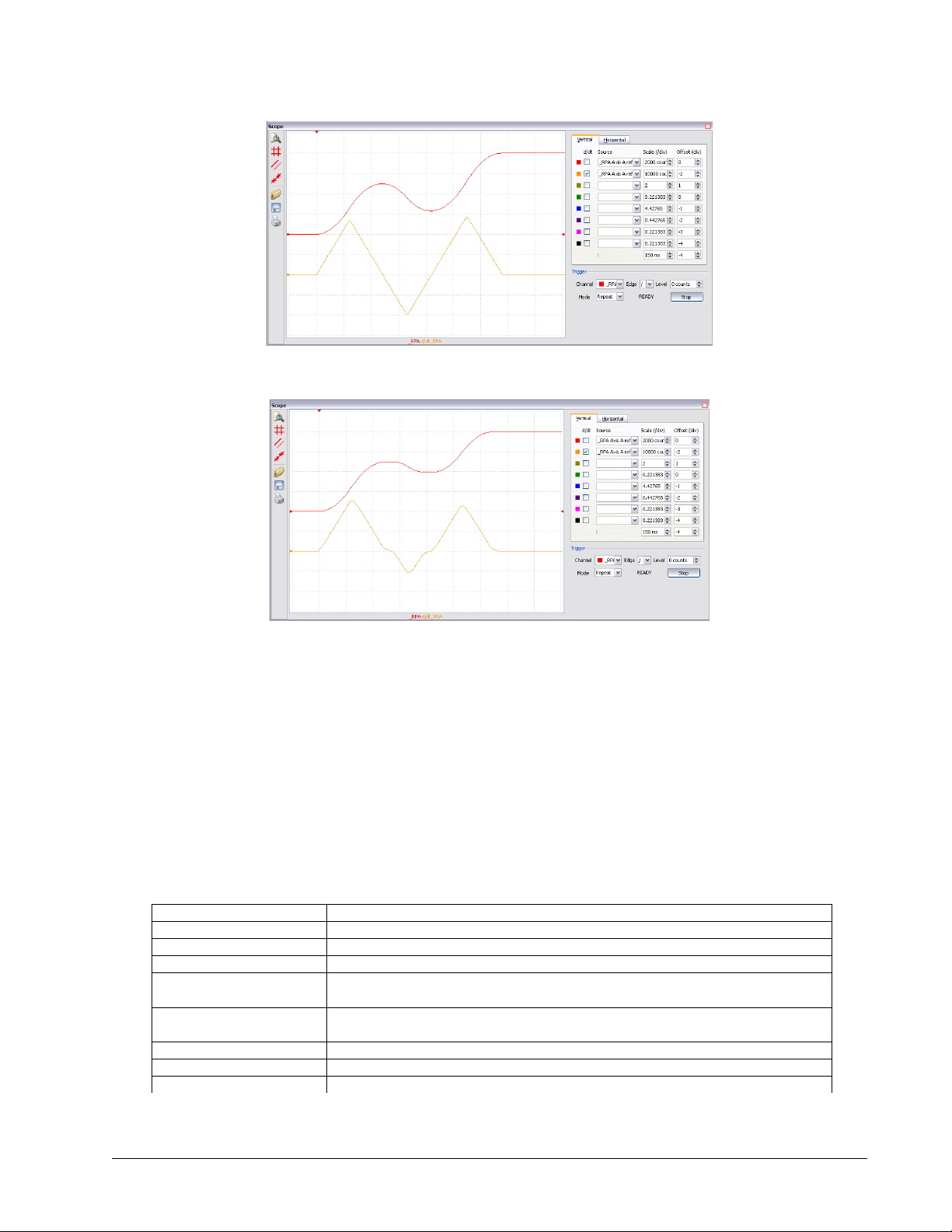
Figure 6.4: Position and Velocity vs Time (msec) for Motion 3
Figure 6.5: Position and Velocity vs Time (msec) for Motion 3 with IT 0.1
Note the controller treats the point where the velocity passes through zero as the end of one move, and the
beginning of another move. IT is allowed, however it will introduce some time delay.
Trippoints
Most trippoints are valid for use while in the position tracking mode. There are a few exceptions to this; the AM
and MC commands may not be used while in this mode. It is recommended that MF, MR, or AP be used, as they
involve motion in a specified direction, or the passing of a specific absolute position.
Command Summary – Position Tracking Mode
COMMAND DESCRIPTION
AC n,n,n,n,n,n,n,n
AP n,n,n,n,n,n,n,n
DC n,n,n,n,n,n,n,n
MF n,n,n,n,n,n,n,n
MR n,n,n,n,n,n,n,n
PT n,n,n,n,n,n,n,n
PA n,n,n,n,n,n,n,n
SP n,n,n,n,n,n,n,n
Chapter 6 Programming Motion ▫ 78 DMC-40x0 User Manual
Acceleration settings for the specified axes
Trippoint that holds up program execution until an absolute position has been reached
Deceleration settings for the specified axes
Trippoint to hold up program execution until n number of counts have passed in the
forward direction. Only one axis at a time may be specified.
Trippoint to hold up program execution until n number of counts have passed in the
reverse direction. Only one axis at a time may be specified.
Command used to enter and exit the Trajectory Modification Mode
Command Used to specify the absolute position target
Speed settings for the specified axes

Linear Interpolation Mode
The DMC-40x0 provides a linear interpolation mode for 2 or more axes. In linear interpolation mode, motion
between the axes is coordinated to maintain the prescribed vector speed, acceleration, and deceleration along the
specified path. The motion path is described in terms of incremental distances for each axis. An unlimited number
of incremental segments may be given in a continuous move sequence, making the linear interpolation mode ideal
for following a piece-wise linear path. There is no limit to the total move length.
The LM command selects the Linear Interpolation mode and axes for interpolation. For example, LM YZ selects
only the Y and Z axes for linear interpolation.
When using the linear interpolation mode, the LM command only needs to be specified once unless the axes for
linear interpolation change.
Specifying Linear Segments
The command LI x,y,z,w or LI a,b,c,d,e,f,g,h specifies the incremental move distance for each axis. This means
motion is prescribed with respect to the current axis position. Up to 511 incremental move segments may be given
prior to the Begin Sequence (BGS) command. Once motion has begun, additional LI segments may be sent to the
controller.
The clear sequence (CS) command can be used to remove LI segments stored in the buffer prior to the start of the
motion. To stop the motion, use the instructions STS or AB. The command, ST, causes a decelerated stop. The
command, AB, causes an instantaneous stop and aborts the program, and the command AB1 aborts the motion
only.
The Linear End (LE) command must be used to specify the end of a linear move sequence. This command tells the
controller to decelerate to a stop following the last LI command. If an LE command is not given, an Abort AB1 must
be used to abort the motion sequence.
It is the responsibility of the user to keep enough LI segments in the DMC-40x0 sequence buffer to ensure
continuous motion. If the controller receives no additional LI segments and no LE command, the controller will
stop motion instantly at the last vector. There will be no controlled deceleration. LM? or _LM returns the available
spaces for LI segments that can be sent to the buffer. 511 returned means the buffer is empty and 511 LI segments
can be sent. A zero means the buffer is full and no additional segments can be sent. As long as the buffer is not
full, additional LI segments can be sent at PC bus speeds.
The instruction _CS returns the segment counter. As the segments are processed, _CS increases, starting at zero.
This function allows the host computer to determine which segment is being processed.
Additional Commands
The commands VS n, VA n, and VD n are used to specify the vector speed, acceleration and deceleration. The DMC40x0 computes the vector speed based on the axes specified in the LM mode. For example, LM XYZ designates
linear interpolation for the X,Y and Z axes. The vector speed for this example would be computed using the
equation:
VS2=XS2+YS2+ZS2, where XS, YS and ZS are the speed of the X,Y and Z axes.
The controller always uses the axis specifications from LM, not LI, to compute the speed.
IT is used to set the S-curve smoothing constant for coordinated moves. The command AV n is the ‘After Vector’
trippoint, which halts program execution until the vector distance of n has been reached.
Chapter 6 Programming Motion ▫ 79 DMC-40x0 User Manual

An Example of Linear Interpolation Motion:
#LMOVE
DP 0,0
LMXY
LI 5000,0
LI 0,5000
LE
VS 4000
BGS
AV 4000
VS 1000
AV 5000
VS 4000
EN
In this example, the XY system is required to perform a 90 turn. In order to slow the speed around the corner, we
use the AV 4000 trippoint, which slows the speed to 1000 count/s. Once the motors reach the corner, the speed is
increased back to 4000 counts / s.
label
Define position of X and Y axes to be 0
Define linear mode between X and Y axes.
Specify first linear segment
Specify second linear segment
End linear segments
Specify vector speed
Begin motion sequence
Set trippoint to wait until vector distance of 4000 is reached
Change vector speed
Set trippoint to wait until vector distance of 5000 is reached
Change vector speed
Program end
Specifying Vector Speed for Each Segment
The instruction VS has an immediate effect and, therefore, must be given at the required time. In some
applications, such as CNC, it is necessary to attach various speeds to different motion segments. This can be done
by two functions: < n and > m
For example:LI x,y,z,w < n >m
The first command, < n, is equivalent to commanding VSn at the start of the given segment and will cause an
acceleration toward the new commanded speeds, subjects to the other constraints.
The second function, > m, requires the vector speed to reach the value m at the end of the segment. Note that the
function > m may start the deceleration within the given segment or during previous segments, as needed to meet
the final speed requirement, under the given values of VA and VD.
Note, however, that the controller works with one > m command at a time. As a consequence, one function may
be masked by another. For example, if the function >100000 is followed by >5000, and the distance for
deceleration is not sufficient, the second condition will not be met. The controller will attempt to lower the speed
to 5000, but will reach that at a different point.
As an example, consider the following program.
#ALT
DP 0,0
LMXY
LI 4000,0 <4000 >1000
LI 1000,1000 < 4000 >1000
LI 0,5000 < 4000 >1000
LE
BGS
EN
Label for alternative program
Define Position of X and Y axis to be 0
Define linear mode between X and Y axes.
Specify first linear segment with a vector speed of 4000 and end speed 1000
Specify second linear segment with a vector speed of 4000 and end speed 1000
Specify third linear segment with a vector speed of 4000 and end speed 1000
End linear segments
Begin motion sequence
Program end
Changing Feed Rate:
The command VR n allows the feed rate, VS, to be scaled between 0 and 10 with a resolution of .0001. This
command takes effect immediately and causes VS to be scaled. VR also applies when the vector speed is specified
with the ‘<’ operator. This is a useful feature for feed rate override. VR does not ratio the accelerations. For
example, VR .5 results in the specification VS 2000 to be divided in half.
Chapter 6 Programming Motion ▫ 80 DMC-40x0 User Manual

Command Summary - Linear Interpolation
VS VZ VW
2 2
COMMAND DESCRIPTION
LM xyzw
LM abcdefgh
LM?
LI x,y,z,w < n
LI a,b,c,d,e,f,g,h < n
VS n
VA n
VD n
VR n
BGS
CS
LE
LE?
AMS
AV n
IT
Specify axes for linear interpolation
(same) controllers with 5 or more axes
Returns number of available spaces for linear segments in DMC-40x0 sequence
buffer. Zero means buffer full. 511 means buffer empty.
Specify incremental distances relative to current position, and assign vector speed
n.
Specify vector speed
Specify vector acceleration
Specify vector deceleration
Specify the vector speed ratio
Begin Linear Sequence
Clear sequence
Linear End- Required at end of LI command sequence
Returns the length of the vector (resets after 2147483647)
Trippoint for After Sequence complete
Trippoint for After Relative Vector distance, n
S curve smoothing constant for vector moves
Operand Summary - Linear Interpolation
OPERAND DESCRIPTION
_AV
_CS
_LE
_LM
_VPm
Return distance traveled
Segment counter - returns number of the segment in the sequence, starting at zero.
Returns length of vector (resets after 2147483647)
Returns number of available spaces for linear segments in DMC-40x0 sequence buffer.
Zero means buffer full. 511 means buffer empty.
Return the absolute coordinate of the last data point along the trajectory.
(m=X,Y,Z or W or A,B,C,D,E,F,G or H)
To illustrate the ability to interrogate the motion status, consider the first motion segment of our example,
#LMOVE, where the X axis moves toward the point X=5000. Suppose that when X=3000, the controller is
interrogated using the command ‘MG _AV’. The returned value will be 3000. The value of _CS, _VPX and _VPY will
be zero.
Now suppose that the interrogation is repeated at the second segment when Y=2000. The value of _AV at this
point is 7000, _CS equals 1, _VPX=5000 and _VPY=0.
Example - Linear Move
Make a coordinated linear move in the ZW plane. Move to coordinates 40000,30000 counts at a vector speed of
100000 counts/sec and vector acceleration of 1000000 counts/sec2.
LM ZW
LI,,40000,30000
LE
VS 100000
VA 1000000
VD 1000000
BGS
Note that the above program specifies the vector speed, VS, and not the actual axis speeds VZ and VW. The axis
speeds are determined by the controller from:
Specify axes for linear interpolation
Specify ZW distances
Specify end move
Specify vector speed
Specify vector acceleration
Specify vector deceleration
Begin sequence
Chapter 6 Programming Motion ▫ 81 DMC-40x0 User Manual

The result is shown in Figure 6.6: Linear Interpolation.
POSITION Z
0
0
40000
FEEDRATE
0
0.1
0.5
0.6
4000
36000
30000
27000
3000
VELOCITY
Z-AXIS
VELOCITY
W-AXIS
POSITION W
TIME (sec)
TIME (sec)
TIME (sec)
Figure 6.6: Linear Interpolation
Example - Multiple Moves
This example makes a coordinated linear move in the XY plane. The Arrays VX and VY are used to store 750
incremental distances which are filled by the program #LOAD.
#LOAD
DM VX [750],VY [750]
COUNT=0
N=0
#LOOP
VX [COUNT]=N
VY [COUNT]=N
N=N+10
COUNT=COUNT+1
JP #LOOP,COUNT<750
#A
LM XY
COUNT=0
#LOOP2;JP#LOOP2,_LM=0
JS#C,COUNT=500
LI VX[COUNT],VY[COUNT]
COUNT=COUNT+1
JP #LOOP2,COUNT<750
LE
AMS
MG “DONE”
EN
#C;BGS;EN
Load Program
Define Array
Initialize Counter
Initialize position increment
LOOP
Fill Array VX
Fill Array VY
Increment position
Increment counter
Loop if array not full
Label
Specify linear mode for XY
Initialize array counter
If sequence buffer full, wait
Begin motion on 500th segment
Specify linear segment
Increment array counter
Repeat until array done
End Linear Move
After Move sequence done
Send Message
End program
Begin Motion Subroutine
Vector Mode: Linear and Circular Interpolation Motion
The DMC-40x0 allows a long 2-D path consisting of linear and arc segments to be prescribed. Motion along the
path is continuous at the prescribed vector speed even at transitions between linear and circular segments. The
Chapter 6 Programming Motion ▫ 82 DMC-40x0 User Manual

DMC-40x0 performs all the complex computations of linear and circular interpolation, freeing the host PC from this
time intensive task.
The coordinated motion mode is similar to the linear interpolation mode. Any pair of two axes may be selected for
coordinated motion consisting of linear and circular segments. In addition, a third axis can be controlled such that
it remains tangent to the motion of the selected pair of axes. Note that only one pair of axes can be specified for
coordinated motion at any given time.
The command VM m,n,p where ‘m’ and ‘n’ are the coordinated pair and p is the tangent axis (Note: the commas
which separate m,n and p are not necessary). For example, VM XWZ selects the XW axes for coordinated motion
and the Z-axis as the tangent.
Specifying the Coordinate Plane
The DMC-40x0 allows for 2 separate sets of coordinate axes for linear interpolation mode or vector mode. These
two sets are identified by the letters S and T.
To specify vector commands the coordinate plane must first be identified. This is done by issuing the command
CAS to identify the S plane or CAT to identify the T plane. All vector commands will be applied to the active
coordinate system until changed with the CA command.
Specifying Vector Segments
The motion segments are described by two commands; VP for linear segments and CR for circular segments. Once
a set of linear segments and/or circular segments have been specified, the sequence is ended with the command
VE. This defines a sequence of commands for coordinated motion. Immediately prior to the execution of the first
coordinated movement, the controller defines the current position to be zero for all movements in a sequence.
Note: This ‘local’ definition of zero does not affect the absolute coordinate system or subsequent coordinated
motion sequences.
The command, VP x,y specifies the coordinates of the end points of the vector movement with respect to the
starting point. Non-sequential axis do not require comma delimitation. The command, CR r,q,d define a circular
arc with a radius r, starting angle of q, and a traversed angle d. The notation for q is that zero corresponds to the
positive horizontal direction, and for both q and d, the counter-clockwise (CCW) rotation is positive.
Up to 511 segments of CR or VP may be specified in a single sequence and must be ended with the command VE.
The motion can be initiated with a Begin Sequence (BGS) command. Once motion starts, additional segments may
be added.
The Clear Sequence (CS) command can be used to remove previous VP and CR commands which were stored in the
buffer prior to the start of the motion. To stop the motion, use the instructions STS or AB1. ST stops motion at the
specified deceleration. AB1 aborts the motion instantaneously.
The Vector End (VE) command must be used to specify the end of the coordinated motion. This command requires
the controller to decelerate to a stop following the last motion requirement. If a VE command is not given, an
Abort (AB1) must be used to abort the coordinated motion sequence.
It is the responsibility of the user to keep enough motion segments in the DMC-40x0 sequence buffer to ensure
continuous motion. If the controller receives no additional motion segments and no VE command, the controller
will stop motion instantly at the last vector. There will be no controlled deceleration. LM? or _LM returns the
available spaces for motion segments that can be sent to the buffer. 511 returned means the buffer is empty and
511 segments can be sent. A zero means the buffer is full and no additional segments can be sent. As long as the
buffer is not full, additional segments can be sent at PC bus speeds.
The operand _CS can be used to determine the value of the segment counter.
Chapter 6 Programming Motion ▫ 83 DMC-40x0 User Manual

Additional commands
The commands VS n, VA n and VD n are used for specifying the vector speed, acceleration, and deceleration.
IT is the s curve smoothing constant used with coordinated motion.
Specifying Vector Speed for Each Segment:
The vector speed may be specified by the immediate command VS. It can also be attached to a motion segment
with the instructions
VP x,y < n >m
CR r, ɵ,δ< n >m
The first command, <n, is equivalent to commanding VSn at the start of the given segment and will cause an
acceleration toward the new commanded speeds, subjects to the other constraints.
The second function, > m, requires the vector speed to reach the value m at the end of the segment. Note that the
function > m may start the deceleration within the given segment or during previous segments, as needed to meet
the final speed requirement, under the given values of VA and VD.
Note, however, that the controller works with one > m command at a time. As a consequence, one function may
be masked by another. For example, if the function >100000 is followed by >5000, and the distance for
deceleration is not sufficient, the second condition will not be met. The controller will attempt to lower the speed
to 5000, but will reach that at a different point.
Changing Feed Rate:
The command VR n allows the feed rate, VS, to be scaled between 0 and 10 with a resolution of .0001. This
command takes effect immediately and causes VS scaled. VR also applies when the vector speed is specified with
the ‘<’ operator. This is a useful feature for feed rate override. VR does not ratio the accelerations. For example,
VR 0.5 results in the specification VS 2000 to be divided by two.
Compensating for Differences in Encoder Resolution:
By default, the DMC-40x0 uses a scale factor of 1:1 for the encoder resolution when used in vector mode. If this is
not the case, the command, ES can be used to scale the encoder counts. The ES command accepts two arguments
which represent the number of counts for the two encoders used for vector motion. The smaller ratio of the two
numbers will be multiplied by the higher resolution encoder. For more information, see ES command in the
Command Reference.
Trippoints:
The AV n command is the After Vector trippoint, which waits for the vector relative distance of n to occur before
executing the next command in a program.
Tangent Motion:
Several applications, such as cutting, require a third axis (i.e. a knife blade), to remain tangent to the coordinated
motion path. To handle these applications, the DMC-40x0 allows one axis to be specified as the tangent axis. The
VM command provides parameter specifications for describing the coordinated axes and the tangent axis.
VM m,n,p
m,n specifies coordinated axes p specifies tangent axis such as X,Y,Z,W p=N
turns off tangent axis
Before the tangent mode can operate, it is necessary to assign an axis via the VM command and define its offset
and scale factor via the TN m,n command. m defines the scale factor in counts/degree and n defines the tangent
position that equals zero degrees in the coordinated motion plane. The operand _TN can be used to return the
initial position of the tangent axis.
Chapter 6 Programming Motion ▫ 84 DMC-40x0 User Manual

Example:
Assume an XY table with the Z-axis controlling a knife. The Z-axis has a 2000 quad counts/rev encoder and has
been initialized after power-up to point the knife in the +Y direction. A 180° circular cut is desired, with a radius of
3000, center at the origin and a starting point at (3000,0). The motion is CCW, ending at (-3000,0). Note that the
0° position in the XY plane is in the +X direction. This corresponds to the position -500 in the Z-axis, and defines
the offset. The motion has two parts. First, X,Y and Z are driven to the starting point, and later, the cut is
performed. Assume that the knife is engaged with output bit 0.
#EXAMPLE
VM XYZ
TN 2000/360,-500
CR 3000,0,180
VE
CB0
PA 3000,0,_TN
BG XYZ
AM XYZ
SB0
WT50
BGS
AMS
CB0
MG “ALL DONE”
EN
Example program
XY coordinate with Z as tangent
2000/360 counts/degree, position -500 is 0 degrees in XY plane
3000 count radius, start at 0 and go to 180 CCW
End vector
Disengage knife
Move X and Y to starting position, move Z to initial tangent position
Start the move to get into position
When the move is complete
Engage knife
Wait 50 msec for the knife to engage
Do the circular cut
After the coordinated move is complete
Disengage knife
End program
Command Summary - Coordinated Motion Sequence
COMMAND DESCRIPTION
VM m,n
VP m,n
CR r,ɵ,δ<n>m
VS s,t
VA s,t
VD s,t
VR s,t
BGST
CSST
AV s,t
AMST
TN m,n
ES m,n
IT s,t
LM?
CAS or CAT
Specifies the axes for the planar motion where m and n represent the planar axes
and p is the tangent axis.
Return coordinate of last point, where m=X,Y,Z or W.
Specifies arc segment where r is the radius, is the starting angle and is the
travel angle. Positive direction is CCW.
Specify vector speed or feed rate of sequence.
Specify vector acceleration along the sequence.
Specify vector deceleration along the sequence.
Specify vector speed ratio
Begin motion sequence, S or T
Clear sequence, S or T
Trippoint for After Relative Vector distance.
Holds execution of next command until Motion Sequence is complete.
Tangent scale and offset.
Ellipse scale factor.
S curve smoothing constant for coordinated moves
Return number of available spaces for linear and circular segments in DMC-40x0
sequence buffer. Zero means buffer is full. 511 means buffer is empty.
Specifies which coordinate system is to be active (S or T)
Operand Summary - Coordinated Motion Sequence
OPERAND DESCRIPTION
_VPM
_AV
_LM
_CS
_VE
Chapter 6 Programming Motion ▫ 85 DMC-40x0 User Manual
The absolute coordinate of the axes at the last intersection along the sequence.
Distance traveled.
Number of available spaces for linear and circular segments in DMC-40x0 sequence
buffer. Zero means buffer is full. 511 means buffer is empty.
Segment counter - Number of the segment in the sequence, starting at zero.
Vector length of coordinated move sequence.

When AV is used as an operand, _AV returns the distance traveled along the sequence.
Vs Vx Vy
2 2
C (-4000,3000)
R = 1500
B (-4000,0)
D (0,3000)
A (0,0)
The operands _VPX and _VPY can be used to return the coordinates of the last point specified along the path.
Example:
Traverse the path shown in Figure 6.7. Feed rate is 20000 counts/sec. Plane of motion is XY
VM XY
VS 20000
VA 1000000
VD 1000000
VP -4000,0
CR 1500,270,-180
VP 0,3000
CR 1500,90,-180
VE
BGS
The resulting motion starts at the point A and moves toward points B, C, D, A. Suppose that we interrogate the
controller when the motion is halfway between the points A and B.
The value of _AV is 2000
The value of _CS is 0
_VPX and _VPY contain the absolute coordinate of the point A
Suppose that the interrogation is repeated at a point, halfway between the points C and D.
The value of _AV is 4000+1500 +2000=10,712
Specify motion plane
Specify vector speed
Specify vector acceleration
Specify vector deceleration
Segment AB
Segment BC
Segment CD
Segment DA
End of sequence
Begin Sequence
The value of _CS is 2
_VPX,_VPY contain the coordinates of the point C
Figure 6.7: The Required Path
Vector Mode - Mathematical Analysis
The terms of coordinated motion are best explained in terms of the vector motion. The vector velocity, Vs, which is
also known as the feed rate, is the vector sum of the velocities along the X and Y axes, Vx and Vy.
The vector distance is the integral of Vs, or the total distance traveled along the path. To illustrate this further,
suppose that a string was placed along the path in the X-Y plane. The length of that string represents the distance
traveled by the vector motion.
The vector velocity is specified independently of the path to allow continuous motion. The path is specified as a
collection of segments. For the purpose of specifying the path, define a special X-Y coordinate system whose origin
is the starting point of the sequence. Each linear segment is specified by the X-Y coordinate of the final point
Chapter 6 Programming Motion ▫ 86 DMC-40x0 User Manual

expressed in units of resolution, and each circular arc is defined by the arc radius, the starting angle, and the
R
2
360
L Xk Ykk
2 2
L Rk k k 2 360
D Lk
k
n
1
10000 20000
20000
10000
Y
C D
B
A
X
angular width of the arc. The zero angle corresponds to the positive direction of the X-axis and the CCW direction
of rotation is positive. Angles are expressed in degrees, and the resolution is 1/256th of a degree. For example,
the path shown in Figure A.8 is specified by the instructions:
VP 0,10000
CR 10000, 180, -90
VP 20000, 20000
Figure A.8: X-Y Motion Path
The first line describes the straight line vector segment between points A and B. The next segment is a circular arc,
which starts at an angle of 180° and traverses -90°. Finally, the third line describes the linear segment between
points C and D. Note that the total length of the motion consists of the segments:
A-B Linear 10000 units
B-C Circular
= 15708
C-D Linear 10000
Total 35708 counts
In general, the length of each linear segment is
Where Xk and Yk are the changes in X and Y positions along the linear segment. The length of the circular arc is
The total travel distance is given by
The velocity profile may be specified independently in terms of the vector velocity and acceleration.
For example, the velocity profile corresponding to the path of Figure A.8 may be specified in terms of the vector
speed and acceleration.
VS 100000
VA 2000000
The resulting vector velocity is shown in Figure A.9.
Chapter 6 Programming Motion ▫ 87 DMC-40x0 User Manual

The acceleration time, Ta, is given by
T
VS
VA
sa
100000
2000000
0 05.
T
D
VS
T st a
0 407.
0.05 0.357
10000
Velocity
time (s)
0.407T
a
T
a
T
s
A
B
D
(a)
(b)
(c)
time
C
The slew time, Ts, is given by
Figure A.9: Vector Velocity Profile
D
T
s
VS
35708
T s
a
100000
. .
0 0 307
05
The total motion time, Tt, is given by:
The velocities along the X and Y axes are such that the direction of motion follows the specified path, yet the vector
velocity fits the vector speed and acceleration requirements.
For example, the velocities along the X and Y axes for the path shown in Figure A.8 are given in Figure A.10.
Figure A.10 shows the vector velocity. It also indicates the position point along the path starting at A and ending at
D. Between the points A and B, the motion is along the Y axis. Therefore,
Vy = Vs
and
Vx = 0
Between the points B and C, the velocities vary gradually and finally, between the points C and D, the motion is in
the X direction.
Figure A.10: Vector Axes Velocities
Chapter 6 Programming Motion ▫ 88 DMC-40x0 User Manual

Electronic Gearing
This mode allows up to 8 axes to be electronically geared to some master axes. The masters may rotate in both
directions and the geared axes will follow at the specified gear ratio. The gear ratio may be different for each axis
and changed during motion.
The command GAX yzw or GA ABCDEFGH specifies the master axes. GR x,y,z,w specifies the gear ratios for the
slaves where the ratio may be a number between ±127.9999 with a fractional resolution of .0001. There are two
modes: standard gearing and gantry mode. The gantry mode (enabled with the command GM) allows the gearing
to stay enabled even if a limit is hit or an ST command is issued. GR 0,0,0,0 turns off gearing in both modes.
The command GM x,y,z,w select the axes to be controlled under the gantry mode. The parameter 1 enables gantry
mode, and 0 disables it.
GR causes the specified axes to be geared to the actual position of the master. The master axis is commanded with
motion commands such as PR, PA or JG.
When the master axis is driven by the controller in the jog mode or an independent motion mode, it is possible to
define the master as the command position of that axis, rather than the actual position. The designation of the
commanded position master is by the letter, C. For example, GACX indicates that the gearing is the commanded
position of X.
An alternative gearing method is to synchronize the slave motor to the commanded vector motion of several axes
performed by GAS. For example, if the X and Y motor form a circular motion, the Z axis may move in proportion to
the vector move. Similarly, if X,Y and Z perform a linear interpolation move, W can be geared to the vector move.
Electronic gearing allows the geared motor to perform a second independent or coordinated move in addition to
the gearing. For example, when a geared motor follows a master at a ratio of 1:1, it may be advanced an additional
distance with PR, or JG, commands, or VP, or LI.
Ramped Gearing
In some applications, especially when the master is traveling at high speeds, it is desirable to have the gear ratio
ramp gradually to minimize large changes in velocity on the slave axis when the gearing is engaged. For example if
the master axis is already traveling at 500,000 counts/sec and the slave will be geared at a ratio of 1:1 when the
gearing is engaged, the slave will instantly develop following error, and command maximum current to the motor.
This can be a large shock to the system. For many applications it is acceptable to slowly ramp the engagement of
gearing over a greater time frame. Galil allows the user to specify an interval of the master axis over which the
gearing will be engaged. For example, the same master X axis in this case travels at 500,000 counts/sec, and the
gear ratio is 1:1, but the gearing is slowly engaged over 30,000 counts of the master axis, greatly diminishing the
initial shock to the slave axis. Figure 6.Error: Reference source not found below shows the velocity vs. time profile
for instantaneous gearing. Figure 6.14 shows the velocity vs. time profile for the gradual gearing engagement.
Chapter 6 Programming Motion ▫ 89 DMC-40x0 User Manual

Figure 6.11: Velocity counts/sec vs. Time (msec) Instantaneous Gearing Engagement
Figure 6.12: Velocity (counts/sec) vs. Time (msec) Ramped Gearing
The slave axis for each figure is shown on the bottom portion of the figure; the master axis is shown on the top
portion. The shock to the slave axis will be significantly less in Figure 6.14 than in Figure 6.Error: Reference source
not found. The ramped gearing does have one consequence. There isn’t a true synchronization of the two axes,
until the gearing ramp is complete. The slave will lag behind the true ratio during the ramp period. If exact
position synchronization is required from the point gearing is initiated, then the position must be commanded in
addition to the gearing. The controller keeps track of this position phase lag with the _GP operand. The following
example will demonstrate how the command is used.
Example – Electronic Gearing Over a Specified Interval
Objective Run two geared motors at speeds of 1.132 and -.045 times the speed of an external master. Because the
master is traveling at high speeds, it is desirable for the speeds to change slowly.
Solution: Use a DMC-4030 controller where the Z-axis is the master and X and Y are the geared axes. We will
implement the gearing change over 6000 counts (3 revolutions) of the master axis.
MO Z
GA Z, Z
GD 6000,6000
GR 1.132,-.045
Chapter 6 Programming Motion ▫ 90 DMC-40x0 User Manual
Turn Z off, for external master
Specify Z as the master axis for both X and Y.
Specify ramped gearing over 6000 counts of the master axis.
Specify gear ratios

Question: What is the effect of the ramped gearing?
Answer: Below, in the example titled Electronic Gearing, gearing would take effect immediately. From the start of
gearing if the master traveled 6000 counts, the slaves would travel 6792 counts and 270 counts.
Using the ramped gearing, the slave will engage gearing gradually. Since the gearing is engaged over the interval of
6000 counts of the master, the slave will only travel ~3396 counts and ~135 counts respectively. The difference
between these two values is stored in the _GPn operand. If exact position synchronization is required, the IP
command is used to adjust for the difference.
Command Summary - Electronic Gearing
COMMAND DESCRIPTION
GA n
GD a,b,c,d,e,f,g,h
_GPn
GR a,b,c,d,e,f,g,h
GM a,b,c,d,e,f,g,h
MR x,y,z,w
MF x,y,z,w
Specifies master axes for gearing where:
n = X,Y,Z or W or A,B,C,D,E,F,G,H for main encoder as master
n = CX,CY,CZ, CW or CA, CB,CC,CD,CE,CF,CG,CH for commanded position.
n = DX,DY,DZ or DW or DA, DB, DC, DD, DE, DF,DG,DH for auxiliary encoders
n = S or T for gearing to coordinated motion.
Sets the distance the master will travel for the gearing change to take full effect.
This operand keeps track of the difference between the theoretical distance traveled if
gearing changes took effect immediately, and the distance traveled since gearing
changes take effect over a specified interval.
Sets gear ratio for slave axes. 0 disables electronic gearing for specified axis.
X = 1 sets gantry mode, 0 disables gantry mode
Trippoint for reverse motion past specified value. Only one field may be used.
Trippoint for forward motion past specified value. Only one field may be used.
Example - Simple Master Slave
Master axis moves 10000 counts at slew speed of 100000 counts/sec. Y is defined as the master. X,Z,W are geared
to master at ratios of 5,-.5 and 10 respectively.
GA Y,,Y,Y
GR 5,,-.5,10
PR ,10000
SP ,100000
BGY
Specify master axes as Y
Set gear ratios
Specify Y position
Specify Y speed
Begin motion
Example - Electronic Gearing
Objective: Run two geared motors at speeds of 1.132 and -0.045 times the speed of an external master. The
master is driven at speeds between 0 and 1800 RPM (2000 counts/rev encoder).
Solution: Use a DMC-4030 controller, where the Z-axis is the master and X and Y are the geared axes.
MO Z
GA Z, Z
GR 1.132,-.045
Turn Z off, for external master
Specify Z as the master axis for both X and Y.
Specify gear ratios
Now suppose the gear ratio of the X-axis is to change on-the-fly to 2. This can be achieved by commanding:
GR 2
Specify gear ratio for X axis to be 2
Example - Gantry Mode
In applications where both the master and the follower are controlled by the DMC-40x0 controller, it may be
desired to synchronize the follower with the commanded position of the master, rather than the actual position.
This eliminates the coupling between the axes which may lead to oscillations.
Chapter 6 Programming Motion ▫ 91 DMC-40x0 User Manual

For example, assume that a gantry is driven by two axes, X,Y, on both sides. This requires the gantry mode for
strong coupling between the motors. The X-axis is the master and the Y-axis is the follower. To synchronize Y with
the commanded position of X, use the instructions:
GA, CX
GR,1
GM,1
PR 3000
BG X
Specify the commanded position of X as master for Y.
Set gear ratio for Y as 1:1
Set gantry mode
Command X motion
Start motion on X axis
You may also perform profiled position corrections in the electronic gearing mode. Suppose, for example, that you
need to advance the slave 10 counts. Simply command
IP ,10
Specify an incremental position movement of 10 on Y axis.
Under these conditions, this IP command is equivalent to:
PR,10
BGY
Specify position relative movement of 10 on Y axis
Begin motion on Y axis
Often the correction is quite large. Such requirements are common when synchronizing cutting knives or conveyor
belts.
Example - Synchronize two conveyor belts with trapezoidal velocity correction
GA,X
GR,2
PR,300
SP,5000
AC,100000
DC,100000
BGY
Define X as the master axis for Y.
Set gear ratio 2:1 for Y
Specify correction distance
Specify correction speed
Specify correction acceleration
Specify correction deceleration
Start correction
Electronic Cam
The electronic cam is a motion control mode which enables the periodic synchronization of several axes of motion.
Up to 7 axes can be slaved to one master axis. The master axis encoder must be input through a main encoder
port.
The electronic cam is a more general type of electronic gearing which allows a table-based relationship between
the axes. It allows synchronizing all the controller axes. For example, the DMC-4080 controllers may have one
master and up to seven slaves.
To illustrate the procedure of setting the cam mode, consider the cam relationship for the slave axis Y, when the
master is X. Such a graphic relationship is shown in Figure 6.13.
Step 1. Selecting the master axis
The first step in the electronic cam mode is to select the master axis. This is done with the instruction
EAp where p = X,Y,Z,W,E,F,G,H
p is the selected master axis
For the given example, since the master is x, we specify EAX
Step 2. Specify the master cycle and the change in the slave axis (or axes).
In the electronic cam mode, the position of the master is always expressed modulo one cycle. In this example, the
position of x is always expressed in the range between 0 and 6000. Similarly, the slave position is also redefined
such that it starts at zero and ends at 1500. At the end of a cycle when the master is 6000 and the slave is 1500,
Chapter 6 Programming Motion ▫ 92 DMC-40x0 User Manual

the positions of both x and y are redefined as zero. To specify the master cycle and the slave cycle change, we use
the instruction EM.
EM x,y,z,w
where x,y,z,w specify the cycle of the master and the total change of the slaves over one cycle.
The cycle of the master is limited to 8,388,607 whereas the slave change per cycle is limited to 2,147,483,647. If
the change is a negative number, the absolute value is specified. For the given example, the cycle of the master is
6000 counts and the change in the slave is 1500. Therefore, we use the instruction:
EM 6000,1500
Step 3. Specify the master interval and starting point.
Next we need to construct the ECAM table. The table is specified at uniform intervals of master positions. Up to
256 intervals are allowed. The size of the master interval and the starting point are specified by the instruction:
EP m,n
where m is the interval width in counts, and n is the starting point.
For the given example, we can specify the table by specifying the position at the master points of 0, 2000, 4000 and
6000. We can specify that by
EP 2000,0
Step 4. Specify the slave positions.
Next, we specify the slave positions with the instruction
ET[n]=x,y,z,w
where n indicates the order of the point.
The value, n, starts at zero and may go up to 256. The parameters x,y,z,w indicate the corresponding slave position.
For this example, the table may be specified by
ET[0]=,0
ET[1]=,3000
ET[2]=,2250
ET[3]=,1500
This specifies the ECAM table.
Step 5. Enable the ECAM
To enable the ECAM mode, use the command
EB n
where n=1 enables ECAM mode and n=0 disables ECAM mode.
Step 6. Engage the slave motion
To engage the slave motion, use the instruction
EG x,y,z,w
where x,y,z,w are the master positions at which the corresponding slaves must be engaged.
If the value of any parameter is outside the range of one cycle, the cam engages immediately. When the cam is
engaged, the slave position is redefined, modulo one cycle.
Chapter 6 Programming Motion ▫ 93 DMC-40x0 User Manual

Step 7. Disengage the slave motion
Master X4000
2250
2000 6000
3000
1500
0
To disengage the cam, use the command
EQ x,y,z,w
where x,y,z,w are the master positions at which the corresponding slave axes are disengaged.
Figure 6.13: Electronic Cam Example
This disengages the slave axis at a specified master position. If the parameter is outside the master cycle, the
stopping is instantaneous.
To illustrate the complete process, consider the cam relationship described by
the equation:
Y = 0.5 * X + 100 sin (0.18*X)
where X is the master, with a cycle of 2000 counts.
The cam table can be constructed manually, point by point, or automatically by a program. The following program
includes the set-up.
The instruction EAX defines X as the master axis. The cycle of the master is
2000. Over that cycle, Y varies by 1000. This leads to the instruction EM 2000,1000.
Suppose we want to define a table with 100 segments. This implies increments of 20 counts each. If the master
points are to start at zero, the required instruction is EP 20,0.
The following routine computes the table points. As the phase equals 0.18X and X varies in increments of 20, the
phase varies by increments of 3.6 . The program then computes the values of Y according to the equation and
assigns the values to the table with the instruction ET[N] = ,Y.
INSTRUCTION INTERPRETATION
#SETUP
EAX
EM 2000,1000
EP 20,0
N = 0
#LOOP
P = N3.6
S = @SIN [P]*100
Y = N*10+S
ET [N] =, Y
N = N+1
JP #LOOP, N<=100
EN
Label
Select X as master
Cam cycles
Master position increments
Index
Loop to construct table from equation
Note 3.6 = 0.18 * 20
Define sine position
Define slave position
Define table
Repeat the process
Now suppose that the slave axis is engaged with a start signal, input 1, but that both the engagement and
disengagement points must be done at the center of the cycle: X = 1000 and Y = 500. This implies that Y must be
driven to that point to avoid a jump.
Chapter 6 Programming Motion ▫ 94 DMC-40x0 User Manual

This is done with the program:
INSTRUCTION INTERPRETATION
#RUN
EB1
PA,500
SP,5000
BGY
AM
AI1
EG,1000
AI - 1
EQ,1000
EN
Label
Enable cam
starting position
Y speed
Move Y motor
After Y moved
Wait for start signal
Engage slave
Wait for stop signal
Disengage slave
End
Command Summary - Electronic CAM
Command Description
EA p
EB n
EC n
EG x,y,z,w
EM x,y,z,w
EP m,n
EQ m,n
ET[n]
EW
EY
Specifies master axes for electronic cam where:
p = X,Y,Z or W or A,B,C,D,E,F,G,H for main encoder as master or M or N a for virtual axis
master
Enables the ECAM
ECAM counter - sets the index into the ECAM table
Engages ECAM
Specifies the change in position for each axis of the CAM cycle
Defines CAM table entry size and offset
Disengages ECAM at specified position
Defines the ECAM table entries
Widen Segment (see Application Note #2444)
Set ECAM cycle count
Operand Summary - Electronic CAM
Command Description
_EB
_EC
_EGx
_EM
_EP
_EQx
_EY
Contains State of ECAM
Contains current ECAM index
Contains ECAM status for each axis
Contains size of cycle for each axis
Contains value of the ECAM table interval
Contains ECAM status for each axis
Set ECAM cycle count
Example - Electronic CAM
The following example illustrates a cam program with a master axis, Z, and two slaves, X and Y.
Chapter 6 Programming Motion ▫ 95 DMC-40x0 User Manual
 Loading...