

Page 1

DMC-3425
Manual Rev. 1.1b
USER MANUAL
By Galil Motion Control, Inc.
Galil Motion Control, Inc.
3750 Atherton Road
Rocklin, California 95765
Phone: (916) 626-0101
Fax: (916) 626-0102
Internet Address: support@galilmc.com
URL: www.galilmc.com
Rev 6/06
Page 2

Page 3

Contents
Contents i
Chapter 1 Overview 1
Introduction ...............................................................................................................................1
Overview of Motor Types..........................................................................................................2
DMC-3425 Functional Elements ............................................................................................... 4
Standard Servo Motors with +/- 10 Volt Command Signal.........................................2
Stepper Motor with Step and Direction Signals ..........................................................2
Brushless Servo Motor with Sinusoidal Commutation................................................2
Microcomputer Section ...............................................................................................4
Motor Interface............................................................................................................ 4
Communication ........................................................................................................... 4
General I/O..................................................................................................................5
System Elements ......................................................................................................... 5
Motor...........................................................................................................................5
Amplifier (Driver) ....................................................................................................... 5
Encoder........................................................................................................................6
Watch Dog Timer........................................................................................................6
Chapter 2 Getting Started 7
The DMC-3425 Motion Controller............................................................................................ 7
Elements You Need ................................................................................................................... 8
Installing the DMC-3425 Controller.......................................................................................... 8
Step 1. Determine Overall Motor Configuration........................................................ 9
Step 2. Configuring Jumpers on the DMC-3425......................................................... 9
Step 3. Connecting AC or DC power and the Serial Cable to the DMC-3425 .......... 11
Step 4. Installing the Communications Software.......................................................12
Step 5. Establishing Communication between the DMC-3425 and the host PC ....... 12
Step 6. Set-up axis for sinusoidal commutation (optional)....................................... 17
Step 7. Make connections to amplifier and encoder..................................................17
Step 8a. Connect Standard Servo Motor...................................................................19
Step 8b. Connect brushless motor for sinusoidal commutation................................ 23
Step 8c. Connect Step Motors ................................................................................... 26
Step 9. Tune the Servo System.................................................................................. 27
Step 10. Configure the Distributed Control System.................................................. 28
Design Examples .....................................................................................................................32
Example 1 - System Set-up ....................................................................................... 32
Example 2 - Profiled Move .......................................................................................32
Example 3 - Position Interrogation............................................................................ 32
Example 4 - Absolute Position .................................................................................. 32
DMC-3425 Contents • i
Page 4

Example 5 - Velocity Control (Jogging) ...................................................................33
Example 6 - Operation Under Torque Limit .............................................................33
Example 7 - Interrogation.......................................................................................... 33
Example 8 - Operation in the Buffer Mode............................................................... 33
Example 9 - Motion Programs...................................................................................34
Example 10 - Motion Programs with Loops..............................................................34
Example 11- Motion Programs with Trippoints........................................................ 34
Example 12 - Control Variables................................................................................ 35
Example 13 - Control Variables and Offset ..............................................................35
Chapter 3 Connecting Hardware 37
Overview .................................................................................................................................37
Using Inputs............................................................................................................................. 37
Limit Switch Input.....................................................................................................37
Home Switch Input.................................................................................................... 38
Abort Input ................................................................................................................ 38
Uncommitted Digital Inputs ...................................................................................... 39
Amplifier Interface .................................................................................................................. 39
TTL Inputs...............................................................................................................................40
Analog Inputs ..........................................................................................................................40
TTL Outputs ............................................................................................................................ 41
Chapter 4 Communication 43
Introduction .............................................................................................................................43
RS232 Port............................................................................................................................... 43
RS232 - Port 1 DATATERM ................................................................................ 43
RS-232 Configuration ...............................................................................................43
Ethernet Configuration ............................................................................................................44
Communication Protocols ......................................................................................... 44
Addressing................................................................................................................. 44
Ethernet Handles .......................................................................................................45
Global vs. Local Operation........................................................................................45
Operation of Distributed Control...............................................................................47
Accessing the I/O of the Slaves................................................................................. 47
Handling Communication Errors...............................................................................48
Multicasting............................................................................................................... 48
Unsolicited Message Handling.................................................................................. 49
IOC-7007 Support ..................................................................................................... 49
Modbus Support ........................................................................................................ 50
Other Communication Options..................................................................................51
Data Record ............................................................................................................................. 52
Data Record Map....................................................................................................... 52
Explanation of Status Information and Axis Switch Information..............................55
Notes Regarding Velocity and Torque Information .................................................. 56
QZ Command............................................................................................................56
Using Third Party Software....................................................................................... 57
Chapter 5 Command Basics 59
Introduction .............................................................................................................................59
Command Syntax - ASCII....................................................................................................... 59
Coordinated Motion with more than 1 axis............................................................... 60
Command Syntax - Binary ......................................................................................................60
Binary Command Format.......................................................................................... 61
Binary command table...............................................................................................62
ii • Contents DMC-3425
Page 5

Controller Response to DATA ................................................................................................63
Interrogating the Controller ..................................................................................................... 64
Interrogation Commands...........................................................................................64
Summary of Interrogation Commands ...................................................................... 64
Interrogating Current Commanded Values................................................................ 64
Operands....................................................................................................................64
Command Summary.................................................................................................. 65
Chapter 6 Programming Motion 67
Overview .................................................................................................................................67
Global vs. Local Operation........................................................................................67
Independent Axis Positioning.................................................................................................. 69
Command Summary - Independent Axis ..................................................................70
Operand Summary - Independent Axis ..................................................................... 70
Examples ................................................................................................................... 70
Independent Jogging................................................................................................................72
Command Summary - Jogging.................................................................................. 72
Operand Summary - Independent Axis ..................................................................... 72
Examples ................................................................................................................... 72
Linear Interpolation Mode (Local Mode)................................................................................73
Specifying Linear Segments...................................................................................... 73
Additional Commands............................................................................................... 74
Command Summary - Linear Interpolation...............................................................75
Operand Summary - Linear Interpolation..................................................................75
Example..................................................................................................................... 76
Example - Linear Move............................................................................................. 76
Example - Multiple Moves........................................................................................77
Vector Mode: Linear and Circular Interpolation (Local Mode) ..............................................78
Specifying Vector Segments .....................................................................................78
Additional commands................................................................................................ 79
Command Summary - Coordinated Motion Sequence..............................................80
Operand Summary - Coordinated Motion Sequence................................................. 80
Electronic Gearing (Local Mode)............................................................................................ 82
Command Summary - Electronic Gearing ................................................................82
Electronic Cam (Local Mode) .................................................................................................83
Contour Mode (Local Mode)................................................................................................... 89
Specifying Contour Segments ................................................................................... 89
Additional Commands............................................................................................... 91
Command Summary - Contour Mode ....................................................................... 91
Operand Summary - Contour Mode .......................................................................... 91
Virtual Axis (Local Mode) ......................................................................................................94
Ecam Master Example............................................................................................... 95
Sinusoidal Motion Example ...................................................................................... 95
Stepper Motor Operation ......................................................................................................... 95
Specifying Stepper Motor Operation......................................................................... 95
Stepper Motor Smoothing ......................................................................................... 96
Monitoring Generated Pulses vs. Commanded Pulses ..............................................96
Motion Complete Trippoint....................................................................................... 97
Using an Encoder with Stepper Motors..................................................................... 97
Command Summary - Stepper Motor Operation.......................................................97
Operand Summary - Stepper Motor Operation..........................................................97
Dual Loop (Auxiliary Encoder)...............................................................................................98
Using the CE Command............................................................................................ 98
Additional Commands for the Auxiliary Encoder..................................................... 98
Backlash Compensation ............................................................................................98
DMC-3425 Contents• iii
Page 6

Example..................................................................................................................... 99
Motion Smoothing................................................................................................................. 100
Using the IT and VT Commands:............................................................................100
Example................................................................................................................... 100
Homing .................................................................................................................................. 101
Example................................................................................................................... 102
Command Summary - Homing Operation...............................................................104
Operand Summary - Homing Operation.................................................................. 104
High Speed Position Capture (Latch) .................................................................................... 104
Example................................................................................................................... 105
Chapter 7 Application Programming 107
Overview ...............................................................................................................................107
Global vs. Local Programming................................................................................107
Entering Programs .................................................................................................................108
Edit Mode Commands............................................................................................. 108
Example:.................................................................................................................. 109
Program Format..................................................................................................................... 109
Using Labels in Programs .......................................................................................109
Special Labels..........................................................................................................110
Commenting Programs............................................................................................ 110
Executing Programs - Multitasking ....................................................................................... 111
Debugging Programs .............................................................................................................112
Trace Command ...................................................................................................... 113
Error Code Command..............................................................................................113
Stop Code Command...............................................................................................113
RAM Memory Interrogation Commands ................................................................ 113
Operands..................................................................................................................114
Breakpoints and single stepping.............................................................................. 114
EEPROM Memory Interrogation Operands............................................................ 114
Program Flow Commands ..................................................................................................... 115
Event Triggers & Trippoints....................................................................................115
Conditional Jumps...................................................................................................119
If, Else, and Endif.................................................................................................... 121
Subroutines.............................................................................................................. 123
Stack Manipulation..................................................................................................123
Auto-Start and Auto Error Routine .........................................................................123
Automatic Subroutines for Monitoring Conditions.................................................124
Mathematical and Functional Expressions ............................................................................ 127
Mathematical Operators ..........................................................................................127
Bit-Wise Operators.................................................................................................. 128
Functions ................................................................................................................. 129
Variables................................................................................................................................129
Programmable Variables ......................................................................................... 130
Operands................................................................................................................................131
Special Operands.....................................................................................................131
Examples ................................................................................................................. 132
Arrays ....................................................................................................................................132
Defining Arrays.......................................................................................................132
Assignment of Array Entries................................................................................... 132
Uploading and Downloading Arrays to On Board Memory....................................133
Automatic Data Capture into Arrays.......................................................................133
Deallocating Array Space........................................................................................ 135
Outputting Numbers and Strings ........................................................................................... 135
Sending Messages ...................................................................................................135
iv • Contents DMC-3425
Page 7

Displaying Variables and Arrays............................................................................. 137
Interrogation Commands.........................................................................................137
Formatting Variables and Array Elements .............................................................. 139
Converting to User Units......................................................................................... 140
Hardware I/O ......................................................................................................................... 140
Digital Outputs ........................................................................................................ 140
Digital Inputs...........................................................................................................141
Input Interrupt Function ..........................................................................................142
Analog Inputs .......................................................................................................... 142
Extended I/O of the DMC-3425 Controller........................................................................... 143
Configuring the I/O of the DMC-3425.................................................................... 143
Saving the State of the Outputs in Non-Volatile Memory.......................................144
Accessing Extended I/O ..........................................................................................144
Interfacing to Grayhill or OPTO-22 G4PB24 .........................................................145
Example Applications............................................................................................................ 145
Wire Cutter.............................................................................................................. 145
A-B (X-Y) Table Controller....................................................................................146
Speed Control by Joystick....................................................................................... 148
Position Control by Joystick.................................................................................... 149
Chapter 8 Hardware & Software Protection 151
Introduction ...........................................................................................................................151
Hardware Protection .............................................................................................................. 151
Output Protection Lines........................................................................................... 151
Input Protection Lines ............................................................................................. 152
Software Protection ...............................................................................................................152
Example:.................................................................................................................. 152
Programmable Position Limits ................................................................................ 152
Example:.................................................................................................................. 153
Off-On-Error ...........................................................................................................153
Examples: ................................................................................................................ 153
Automatic Error Routine ......................................................................................... 153
Example:.................................................................................................................. 153
Limit Switch Routine ..............................................................................................154
Chapter 9 Troubleshooting 155
Overview ...............................................................................................................................155
Installation ............................................................................................................................. 155
Communication......................................................................................................................156
Stability.................................................................................................................................. 156
Operation ............................................................................................................................... 156
Chapter 10 Theory of Operation 157
Overview ...............................................................................................................................157
Operation of Closed-Loop Systems.......................................................................................159
System Modeling................................................................................................................... 160
Motor-Amplifier......................................................................................................161
Encoder....................................................................................................................163
DAC ........................................................................................................................164
Digital Filter ............................................................................................................ 164
ZOH......................................................................................................................... 165
System Analysis.....................................................................................................................165
System Design and Compensation.........................................................................................167
The Analytical Method............................................................................................ 167
DMC-3425 Contents• v
Page 8

Appendices 171
Electrical Specifications ........................................................................................................171
Servo Control ..........................................................................................................171
Input/Output ............................................................................................................ 171
Power Requirements................................................................................................ 171
Performance Specifications ...................................................................................................171
Connectors for DMC-3425 .................................................................................................... 172
J3 DMC-3425 General I/O; 37- PIN D-type ........................................................... 172
J3 DMC-3425-Stepper General I/O; 37- PIN D-type.............................................. 173
J5 POWER; 6 PIN MOLEX.................................................................................... 173
J1 RS232 Main port: DB-9 Pin Male: ..................................................................... 174
Pin-Out Description............................................................................................................... 174
ICM-1460 Interconnect Module ............................................................................................ 175
Opto-Isolation Option for ICM-1460.....................................................................................177
Opto-isolated inputs: ...............................................................................................177
Opto-isolated outputs: .............................................................................................178
64 Extended I/O of the DMC-3425 Controller...................................................................... 179
Configuring the I/O of the DMC-3425 with DB-14064.......................................... 179
Connector Description:............................................................................................ 181
IOM-1964 Opto-Isolation Module for Extended I/O Controllers.......................................... 183
Description: ............................................................................................................. 183
Overview ................................................................................................................. 184
Configuring Hardware Banks.................................................................................. 185
Digital Inputs...........................................................................................................185
High Power Digital Outputs .................................................................................... 187
Standard Digital Outputs ......................................................................................... 188
Electrical Specifications .......................................................................................... 189
Relevant DMC Commands......................................................................................190
Screw Terminal Listing........................................................................................... 190
Coordinated Motion - Mathematical Analysis....................................................................... 193
List of Other Publications......................................................................................................196
Training Seminars.................................................................................................................. 196
Contacting Us ........................................................................................................................197
WARRANTY ........................................................................................................................ 198
Index 199
vi • Contents DMC-3425
Page 9

Chapter 1 Overview
Introduction
The DMC-3425 provides a highly versatile, powerful form of distributed control where multiple DMC3425 controllers can be linked together on the Ethernet. One DMC-3425 is designated as a “master”
that receives all commands from the host computer and passes them to the other “slave” DMC-3425
controllers. Efficient, quick communications are realized as this approach eliminates the usual,
multiple communication links between the host computer and each controller.
Each DMC-3425 precisely controls two servo motors, providing ECAM, gearing and both linear and
circular interpolation for coordinated motion along the two local axis. A single axis DMC-3415 is also
available. When acting as the “master,” a DMC-3425 can receive PR, PA and JG commands for up to
eight axes and distribute them to the appropriate controller. Coordinated motion is commanded locally
by each DMC-3425 “slave” controller. Performance capability of these controllers includes: 12 MHz
encoder input frequency, 16-bit motor command output DAC, +/-2 billion counts total travel per move,
250 μsec minimum sample rate and non-volatile memory for program and parameter storage.
Designed for maximum flexibility, the DMC-3425 can be interfaced to a variety of motors and drives
including step motors, brush and brushless servo motors and hydraulics. The DMC-3425 can also be
configured to provide sinusoidal commutation for brushless motors.
The controller accepts feedback from a quadrature linear or rotary encoder with input frequencies up to
12 million quadrature counts per second. Modes of motion include jogging, point-to-point positioning,
electronic cam, electronic gearing and contouring. Several motion parameters can be specified
including acceleration and deceleration rates and slew speed. The DMC-3425 also provides motion
smoothing to eliminate jerk.
For synchronization with outside events, the DMC-3425 provides uncommitted I/O. The DMC-3425
provides up to 3 digital inputs, 3 digital outputs and 2 analog inputs. The DMC-3415 provides 7
digital inputs, 3 digital outputs and 2 analog inputs. Committed digital inputs are provided for forward
and reverse limits, abort, home, and definable input interrupts. An additional 64 configurable I/O
points may be added with the optional DB-14064 daughter card. The DMC-3425 distributed system
may also be linked with multiple IOC-7007 Ethernet I/O modules for complete machine I/O control.
Event triggers can automatically check for elapsed time, distance and motion complete.
The DMC-3425 is easy to program. Instructions are represented by two letter commands such as BG
for Begin and SP for Speed. Conditional instructions, Jump statements and arithmetic functions are
included for writing self-contained applications programs. An internal editor allows programs to be
quickly entered and edited, and support software such as the WSDK allows quick system set-up and
tuning. Commands may also be sent in Binary to decrease processing time.
To prevent system damage during machine operation, the DMC-3425 provides many error-handling
features. These include software and hardware limits, automatic shut-off on excessive error, abort
input and user-definable error and limit routines.
DMC-3425 Chapter 1 Overview• 1
Page 10

The DMC-3425 is designed for stand-alone applications and provides non-volatile storage for
programs, variables and array elements.
This manual uses ‘DMC-3425’ to refer to the distributed control E-series from Galil. However, most
functions described in this manual are available using either the DMC-3425 or the DMC-3415. If a
function is specific to only one of the controllers, this will be explicitly stated.
Overview of Motor Types
The DMC-3425 can provide the following types of motor control:
1. Standard servo motors with +/- 10 volt command signals
2. Step motors with step and direction signals
3. Brushless servo motors with sinusoidal commutation
4. Other actuators such as hydraulics - For more information, contact Galil.
The user can configure each axis for any combination of motor types, providing maximum flexibility.
Standard Servo Motors with +/- 10 Volt Command Signal
The DMC-3425 achieves superior precision through use of a 16-bit motor command output DAC and a
sophisticated PID filter that features velocity and acceleration feedforward, an extra notch filter and
integration limits.
The controller is configured by the factory for standard servo motor operation. In this configuration,
the controller provides an analog signal (+/- 10Volt) to connect to a servo amplifier. This connection
is described in Chapter 2.
Stepper Motor with Step and Direction Signals
The DMC-3425 can control 2 stepper motors. In this mode, the controller provides two signals to
connect to each stepper motor: Step and Direction. For stepper motor operation, the controller does
not require an encoder and operates the stepper motor in an open loop. Chapter 2 describes the proper
connection and procedure for using stepper motors.
NOTE: In order to use two stepper motors on the DMC-3425, the controller must be ordered as a
DMC-3425-Stepper. In this mode, the Amp Enable and Error outputs are converted to the Step and
Direction signals for the Y-axis. Contact Galil for other stepper options.
Brushless Servo Motor with Sinusoidal Commutation
The DMC-3415 can provide sinusoidal commutation for brushless motors (BLM). In this
configuration, the controller generates two sinusoidal signals for connection with amplifiers
specifically designed for this purpose. Please note, for a 2 axis DMC-3425, converting to a brushless
motor uses up the second axis.
Note: The task of generating sinusoidal commutation may be accomplished in the brushless motor
amplifier. If the amplifier generates the sinusoidal commutation signals, only a single command signal
is required and the controller should be configured for a standard servo motor (described above).
Sinusoidal commutation in the controller can be used with linear and rotary BLMs. However, the
motor velocity should be limited such that a magnetic cycle lasts at least 6 milliseconds*. For faster
motors, please contact the factory.
The controller provides a one-time, automatic set-up procedure. The parameters determined by this
procedure can then be saved in non-volatile memory to be used whenever the system is powered on.
2 • Chapter 1 Overview DMC-3425
Page 11

The DMC-3415 can control BLMs equipped with Hall sensors as well as without Hall sensors. If hall
sensors are available, once the controller has been setup, the controller will estimate the commutation
phase upon reset. This allows the motor to function immediately upon power up. The Hall effect
sensors also provide a method for setting the precise commutation phase. Chapter 2 describes the
proper connection and procedure for using sinusoidal commutation of brushless motors.
* 6 Milliseconds per magnetic cycle assumes a servo update of 1 msec (default rate).
DMC-3425 Chapter 1 Overview• 3
Page 12
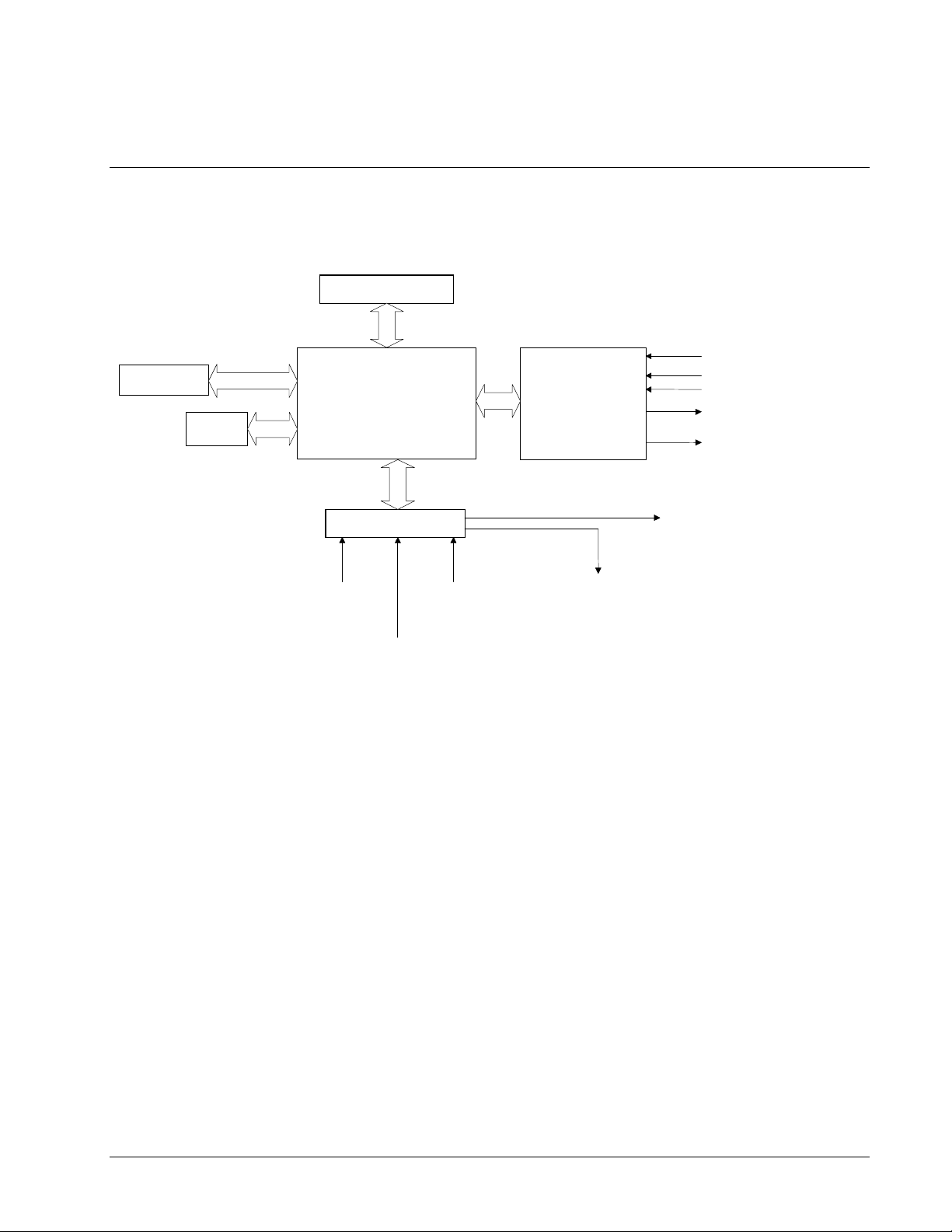
DMC-3425 Functional Elements
The DMC-3425 circuitry can be divided into the following functional groups as shown in Figure 1.1
and discussed below.
ETHERNET
RS-232
WATCHDOG TIMER
68331
MICROCOMPUTER
WITH
1 Meg RAM
4 Meg FLASH EEPROM
HIGH-SPEED
MOTOR/ENCODER
INTERFACE
ISOLATED LIMITS AND
HOME INPUTS
MAIN ENCODERS
AUXILIARY ENCODERS
+/- 10 VOLT OUTPUT FOR
SERVO MOTORS
PULSE/DIRECTION OUTPUT
FOR STEP MOTORS
I/O INTERFACE
2 UNCOMMITTED
ANALOG INPUTS
HIGH-SPEED LATCH FOR EACH AXIS
3 PROGRAMMABLE,
INPUTS
3 PROGRAMMABLE
OUTPUTS
HIGH SPEED ENCODER
COMPARE OUTPUT
Figure 1.1 - DMC-3425 Functional Elements
Microcomputer Section
The main processing unit of the DMC-3425 is a specialized 32-bit Motorola 68331 Series
Microcomputer with 1 Meg RAM and 4 Meg Flash EEPROM. The RAM provides memory for
variables, array elements and application programs. The flash EEPROM provides non-volatile storage
of variables, programs, and arrays. It also contains the DMC-3425 firmware.
Motor Interface
Galil’s GL-1800 custom, sub-micron gate array performs quadrature decoding of each encoder at up to
12 MHz. For standard servo operation, the controller generates a +/-10 Volt analog signal (16 Bit
DAC). For sinusoidal commutation operation, the controller uses two DACs to generate two +/-10Volt
analog signals. For stepper motor operation, the controller generates a step and direction signal.
Communication
The communication interface with the DMC-3425 consists of one RS-232 port (19.2 kbaud) and one
10base-T Ethernet port.
4 • Chapter 1 Overview DMC-3425
Page 13
General I/O
A
The DMC-3415 provides interface circuitry for 7 TTL inputs and 3 TTL outputs. In addition, the
controller provides two 12-bit analog inputs. The general inputs can also be used for triggering a highspeed positional latch for each axis.
NOTE: In order to accommodate 2 axes on the DMC-3425, many of the general I/O features become
dedicated I/O for the second axis. The standard DMC-3425 will have 3 TTL inputs, 3 TTL outputs and
2 analog inputs. If extra I/O is needed, the DB-14064 I/O daughter card increases general purpose I/O
by 64 points.
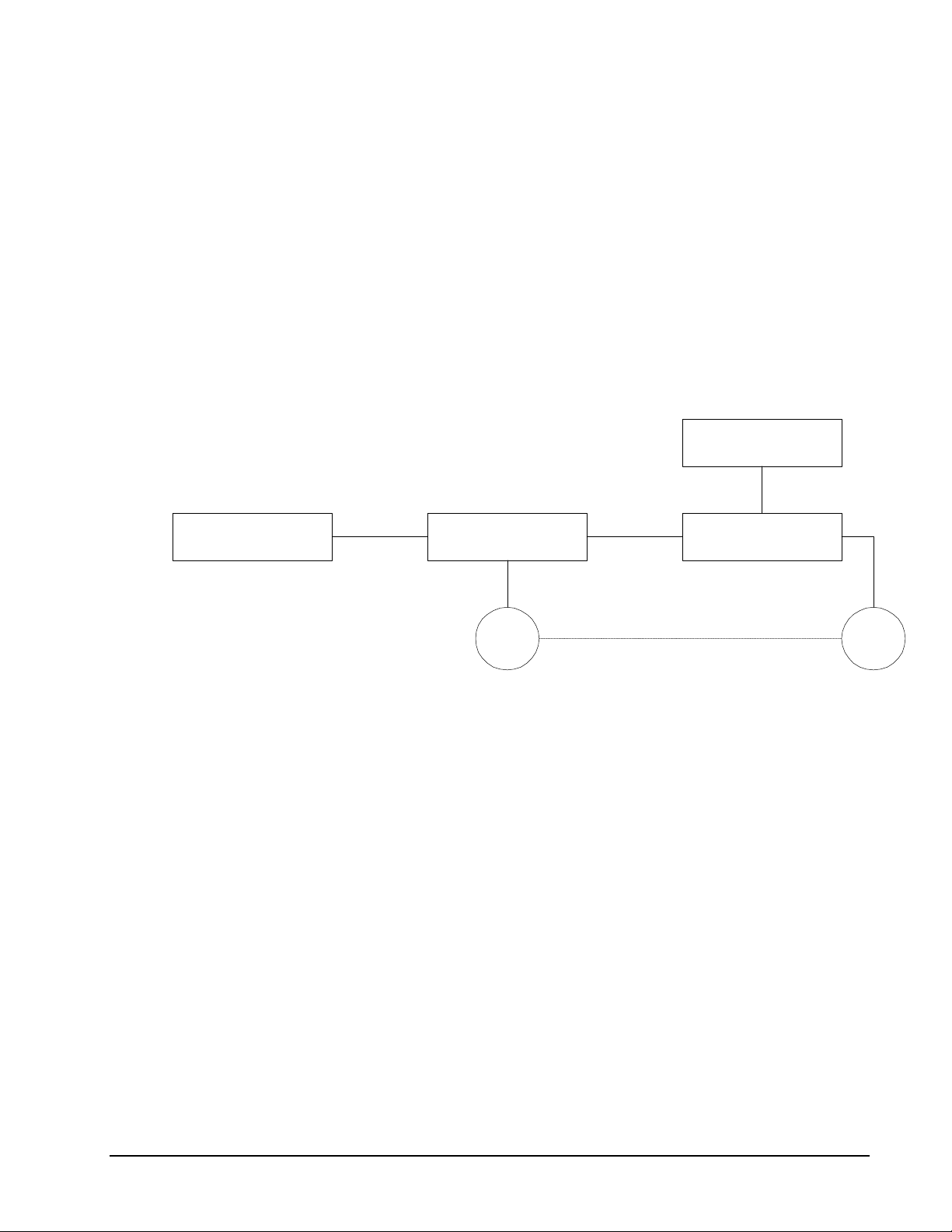
System Elements
As shown in Fig. 1.2, the DMC-3425 is part of a motion control system, which includes amplifiers,
motors and encoders. These elements are described below.
Computer DMC-3425 Controller
Encoder Motor
Figure 1.2 - Elements of Servo systems
Power Supply
mplifier (Driver)
Motor
A motor converts current into torque, which produces motion. Each axis of motion requires a motor
sized properly to move the load at the required speed and acceleration. (Galil's "Motion Component
Selector" software can help you with motor sizing). Contact Galil for more information.
The motor may be a step or servo motor and can be brush-type or brushless, rotary or linear. For step
motors, the controller is capable of controlling full-step, half-step, or microstep drives. An encoder is
not required when step motors are used.
Amplifier (Driver)
For each axis, the power amplifier converts a +/-10 Volt signal from the controller into current to drive
the motor. For stepper motors, the amplifier converts step and direction signals into current. The
amplifier should be sized properly to meet the power requirements of the motor. For brushless motors,
an amplifier that provides electronic commutation is required or the controller must be configured to
provide sinusoidal commutation. The amplifiers may be either pulse-width-modulated (PWM) or
linear. They may also be configured for operation with or without a tachometer. For current
amplifiers, the amplifier gain should be set such that a 10 Volt command generates the maximum
required current. For example, if the peak motor current is 10A, the amplifier gain should be 1 A/V.
For velocity mode amplifiers, 10 Volts should run the motor at the maximum speed.
DMC-3425 Chapter 1 Overview• 5
Page 14

For step motors, the amplifiers should accept step and direction signals.
Encoder
An encoder translates motion into electrical pulses that are fed back into the controller. The DMC-3425
accepts feedback from either a rotary or linear encoder. Typical encoders provide two channels in
quadrature, known as CHA and CHB. This type of encoder is known as a quadrature encoder.
Quadrature encoders may be either single-ended (CHA and CHB) or differential (CHA,CHA-,
CHB,CHB-). The DMC-3425 decodes either type into quadrature states or four times the number of
cycles. Encoders may also have a third channel (or index) for synchronization. The DMC-3425 can
also interface to encoders with pulse and direction signals.
There is no limit on encoder line density; however, the input frequency to the controller must not
exceed 3,000,000 full encoder cycles/second (12,000,000 quadrature counts/sec). For example, if the
encoder line density is 10000 cycles per inch, the maximum speed is 300 inches/second. If higher
encoder frequency is required, please consult the factory.
The standard voltage level is TTL (zero to five volts), however, voltage levels up to 12 Volts are
acceptable. (If using differential signals, 12 Volts can be input directly to the DMC-3425. Singleended 12 Volt signals require a bias voltage input to the complementary inputs.)
The DMC-3425 can accept analog feedback instead of an encoder for any axis. For more information
see description of analog feedback in the Command Reference under the AF command.
To interface with other types of position sensors such as resolvers or absolute encoders, Galil can
customize the controller and command set. Please contact Galil to talk to one of our applications
engineers about your particular system requirements.
Watch Dog Timer
The DMC-3425 provides an internal watch dog timer which checks for proper microprocessor
operation. The timer toggles the Amplifier Enable Output (AEN), which can be used to switch the
amplifiers off in the event of a serious DMC-3425 failure. The AEN output is normally high. During
power-up and if the microprocessor ceases to function properly, the AEN output will go low. The
error light for each axis will also turn on at this stage. A reset is required to restore the DMC-3425 to
normal operation. Consult the factory for a Return Materials Authorization (RMA) number if your
DMC-3425 is damaged.
6 • Chapter 1 Overview DMC-3425
Page 15
Chapter 2 Getting Started
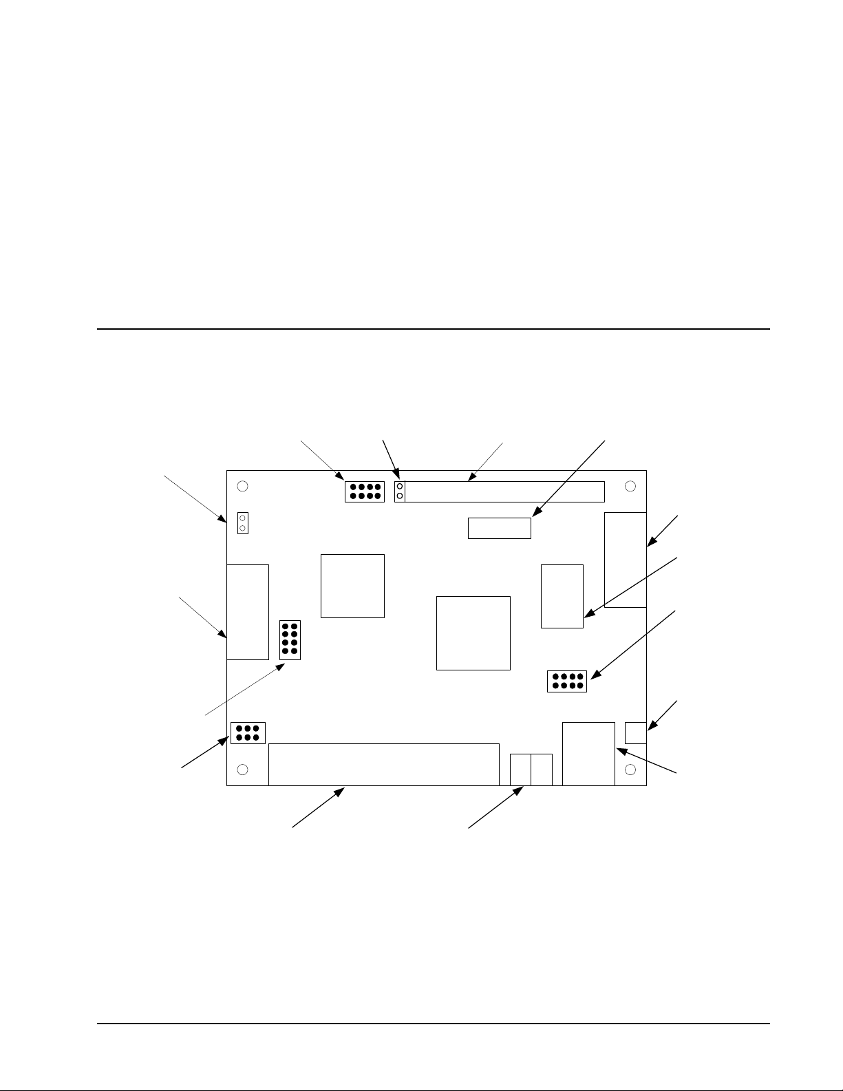
The DMC-3425 Motion Controller
+5V/Gnd Test
Points
6 Pin Molex
Power Connector
Distributed Control Axis
configuration jumpers
Step/Direction or
Motor Command
configuration jumpers
Stepper motor/Motor off
configuration jumpers
+5 G
+12 +5 +5 G G -12
J5
JP3
SD MC
+12V/-12V Test
Points
JP2
+12-12
*
DMC-1415
MO
SMX
SMY
REV D
U1
Motorola
68331
J4
A8
A4
A2
A1
Daughter card connector for
DB-14064 Extended I/O card
U4
GALIL MOTION CONTROL
MADE IN USA
GL-1800
U10
RAM
9-Pin DSub
J6
J1
U2
JP1
1200
9600
MRST
UPGD
J3
J2
D2
D4
SW1
RS232 serial port
Ethernet
network IC
Master reset/baud
rate jumpers
Reset switch
RJ-45 10BaseT
Ethernet connector
Main 37-pin DSub
connector
Status/Communications
LED's
Figure 2.1 – Outline of the DMC-3425
DMC-3425 Chapter 2 Getting Started• 7
Page 16

Elements You Need
Before you start, you must get all the necessary system elements. These include:
1. (1) DMC-3425 or DMC-3415, (1) 37-pin cable (order Cable -37).
2. Servo motor(s) with encoders or stepper motors.
3. Appropriate motor drive - servo amp (Power Amplifier or AMP-1460) or stepper drive.
4. Power Supply for Amplifier
5. +5V, ±12V supply for DMC-3425
6. Communication CD from Galil
7. WSDK Servo Design Software (not necessary, but strongly recommended)
8. Interface Module ICM-1460 with screw-type terminals or integrated Interface
Module/Amplifier, AMP-1460. (Note: An interconnect module is not necessary, but strongly
recommended.) Also, the AMP-1460 only provides for 1 axis power amplification.
The motors may be servo (brush or brushless type) or steppers. The driver (amplifier) should be
suitable for the motor and may be linear or pulse-width-modulated and it may have current feedback or
voltage feedback.
For servo motors, the drivers should accept an analog signal in the +/-10 Volt range as a command.
The amplifier gain should be set so that a +10V command will generate the maximum required current.
For example, if the motor peak current is 10A, the amplifier gain should be 1 A/V. For velocity mode
amplifiers, a command signal of 10 Volts should run the motor at the maximum required speed.
For step motors, the driver should accept step and direction signals. For start-up of a step motor
system refer to Step 8c “Connecting Step Motors”.
The WSDK software is highly recommended for first time users of the DMC-3425. It provides stepby-step instructions for system connection, tuning and analysis.
Installing the DMC-3425 Controller
Installation of a complete, operational DMC-3425 system consists of 9 steps.
Step 1. Determine overall motor configuration.
Step 2. Configuring jumpers on the DMC-3425.
Step 3. Connect the DC power supply and serial cable to the DMC-3425.
Step 4. Install the communications software.
Step 5. Establish communications between the DMC-3425 and the host PC.
Step 6. Set-up axis for sinusoidal commutation.
Step 7. Make connections to amplifier and encoder.
Step 8a. Connect standard servo motor.
Step 8b. Connect brushless motor for sinusoidal commutation.
Step 8c. Connect step motor.
Step 9. Tune servo system.
Step 10. Configure distributed control system.
8 • Chapter 2 Getting Started DMC-3425
Page 17

Step 1. Determine Overall Motor Configuration
Before setting up the motion control system, the user must determine the desired motor configuration.
The DMC-3425 can control standard brush or brushless servo motors, sinusoidally commutated
brushless motors or stepper motors. For control of other types of actuators, such as hydraulics, please
contact Galil. The following configuration information is necessary to determine the proper motor
configuration:
Standard Servo Motor Operation:
The DMC-3425 has been setup by the factory for standard servo motor operation providing an analog
command signal of +/- 10 volt. The position of the jumpers at JP2/JP3 determines the type of output
the controllers will provide, analog motor command or PWM output. The installation of these jumpers
is discussed in the section “Configuring Jumpers on the DMC-3425”. Figure 2.2 shows how the
jumpers are configured for the standard output mode.
The DMC-3425 controller will output the analog command signal to either brush or brushless servo
amplifiers. Please note that if the brushless amplifier provides the sinusoidal commutation, the
standard servo motor operation from the controller will be used. If the commutation is to be performed
by the controller, please see below.
Sinusoidal Commutation:
Please consult the factory before operating with sinusoidal commutation.
Sinusoidal commutation is configured through a single software command, BA. This setting causes
the controller to reconfigure the control axis to output two commutated phases. The DMC-3425
requires two DAC outputs for a single axis of commutation. Issuing the BA command will enable the
second DAC for commutation.
If a DMC-3425 is used for sinusoidal commutation, the second axis will be used for the second DAC
phase. Please note that if the DMC-3425 is used for sinusoidal commutation, it will still be
represented by two axes within the distributed system, even though only one axis is truly active. The
DMC-3415 in brushless mode will take only a single axis within the distributed system.
Further instruction for sinusoidal commutation connections are discussed in Step 6.
Stepper Motor Operation:
The DMC-3415 can be configured to operate in stepper mode by installing a hardware jumper and
issuing a software command. The DMC-3425 can be configured to operate with two stepper motors by
ordering the DMC-3425-Stepper option from the factory. To configure the DMC-3425 for stepper
motor operation, the controller requires a jumper for the stepper motors and the command, MT, must
be given. The installation of the stepper motor jumper is discussed in the following section entitled
"Configuring Jumpers on the DMC-3425". Further instructions for stepper motor connections are
discussed in Step 8b.
Step 2. Configuring Jumpers on the DMC-3425
Master Reset and Upgrade Jumper
JP1 contains two jumpers, MRST and UPGD. The MRST jumper is the Master Reset jumper. When
MRST is connected, the controller will perform a master reset upon PC power up or upon the reset
input going low. Whenever the controller has a master reset, all programs, arrays, variables, and
motion control parameters stored in EEPROM will be ERASED.
The UPGD jumper enables the user to unconditionally update the controller’s firmware. This jumper
is not necessary for firmware updates when the controller is operating normally, but may be necessary
in cases of corrupted EEPROM. EEPROM corruption should never occur, however, it is possible if
DMC-3425 Chapter 2 Getting Started• 9
Page 18
there is a power fault during a firmware update. If EEPROM corruption occurs, your controller may
not operate properly. In this case, install the UPGD Jumper and use the update firmware function on
the Galil Smart Terminal or WSDK to re-load the system firmware.
Setting the Baud Rate on the DMC-3425
The jumpers labeled “9600” and “1200” at JP1 allow the user to select the serial communication baud
rate. The baud rate can be set using the following table:
JUMPER SETTINGS BAUD RATE
9600 1200 --
OFF OFF 19200
ON OFF 9600
OFF ON 1200
The default baud rate for the controller is 19.2k.
Selecting MO as default on the DMC-3425
The default condition for the motor on the DMC-3425 is the servo on (SH) state. This will enable the
amplifiers upon power up of the controller. This state can be changed to the motor off (MO) default by
placing a jumper at JP2 across the MO terminals. This will power up the controller with the amplifiers
disabled and the motor command off. The SH command must then be given in order for the servos or
steppers to operate.
Stepper Motor Jumpers
The DMC-3415 is user configurable to control either a servo motor or a stepper motor. The DMC3425 is factory default to servo control, but may also control two steppers if ordered from the factory
as a DMC-3425-Stepper.
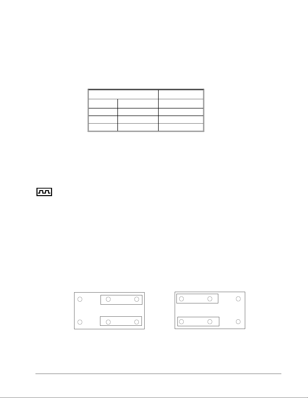
To configure the DMC-3415 for stepper output, two jumpers must be placed on the controller. First,
the SMX jumper at location JP2 must be installed. This configures the board for step/direction output.
Second, the jumpers at location JP3 must be moved from the MC position to the SD position as shown
in Figure 2.2. This configures the output pins on the controller to output step and direction instead of
the analog motor command.
The configuration for two stepper motors on the DMC-3425-Stepper is handled at the factory. The
same procedure is used, placing jumpers on SMX and SMY at location JP2, and moving the SD/MC
jumpers at location JP3. A board modification is also required, which should only be handled by Galil
technicians.
JP3
MCSD
Setting for analog motor command Setting for step/direction output
MC SD
JP3
Figure 2.2 - Jumper settings for motor command output
10 • Chapter 2 Getting Started DMC-3425
Page 19

Axis Configuration Jumpers
When using the HC automatic configuration, jumpers must be set to indicate which controller is the
master and which controllers are slaves. Depending on the configuration of the jumpers, a controller
will be set up as either the A (B) master or any of the axes slaves.
The 8-pin jumper, found at location J4 next to the Molex power connector, is used to select axes
configurations. Jumpers at this location are labeled A1, A2, A4 and A8, which represent the binary
value for each of the 8 axes within a system. The following chart shows proper jumper selection for
each of the DMC-3415 or DMC-3425’s in a system.
Master A (B) axis No Jumpers
Slave Axis B A1 On A2 Off A4 Off A8 Off
Slave Axes C A1 Off A2 On A4 Off A8 Off
Slave Axis D A1 On A2 On A4 Off A8 Off
Slave Axes E A1 Off A2 Off A4 On A8 Off
Slave Axis F A1 On A2 Off A4 On A8 Off
Slave Axes G A1 Off A2 On A4 On A8 Off
Slave Axis H A1 On A2 On A4 On A8 Off
Jumpers on a card are used to denote the first axis it represents in a system. Therefore, a DMC-3415
takes up a single jumper setting. A DMC-3425 is selected with a single jumper setting but represents
two axes.
For example, the jumper settings for a system with a DMC-3415 master A axis, a DMC-3425 slave BC
axis and a DMC-3415 slave D axis, the following jumper settings would be used.
Master A – No Jumpers
Slave Axis BC – A1 On A2 Off A4 Off A8 Off
Slave Axis D – A1 On A2 On A4 Off A8 Off
A1 A2 A4
Fig. 2.3 – Example jumper settings for DMC-3425 E, F axis configuration.
A8
Step 3. Connecting AC or DC power and the Serial Cable to the DMC-3425
1. Insert 37-pin cable to J3. Connect the other end of the cable to the ICM-1460.
2. If using serial communications, use the 9-pin RS232 ribbon cable to connect the SERIAL port
of the DMC-3425 to your computer or terminal communications port. The DMC-3425 serial
DMC-3425 Chapter 2 Getting Started• 11
Page 20

port is configured as DATASET. Your computer or terminal must be configured as a
DATATERM for full duplex, no parity, 8 bits data, one start bit and one stop bit.
Your computer needs to be configured as a "dumb" terminal that sends ASCII characters as
they are typed to the DMC-3425.
Connections to the controller for Ethernet communication are covered in Step 5.
3. If using the card level version, apply ±12V and +5V power to the J5 connector. If using the
box level version, connect the AC cord to a power outlet. AC power requirements for the
controller are single phase, 50 or 60 Hz at 90 to 260 VAC.
4. Applying power will turn on the green LED power indicator.
Step 4. Installing the Communications Software
After applying power to the computer, you should install the Galil software that enables
communication between the controller and PC.
Using DOS:
Using the Galil Software CD-ROM, go to the directory, DMCDOS. Type "INSTALL" at the DOS
prompt and follow the directions.
Using Windows 3.x (16 bit versions):
Using the Galil Software CD ROM, go to the directory, DMCWIN16. Run DMCWIN16.exe at the
Command prompt and follow the directions.
Using Windows 95, NT or 98 (32 bit versions):
The Galil Software CD-ROM will automatically begin the installation procedure when the CD-ROM is
installed. After installing the Galil CD-ROM software on your computer, you can easily install other
software components as desired. To install the basic communications software, run the Galil Software
CD-ROM and choose “DMC Smart Terminal”. This will install the Galil Terminal that can be used
for communication.
Step 5. Establishing Communication between the DMC-3425 and the host PC
Note: This section will show how to communicate with a single DMC-3425 or DMC-3415 controller.
If the controllers will be configured in a multi-axis, distributed control system, only the master axis
needs an IP address actively configured.
Communicating through the RS-232 Serial Communications Port
Connect the DMC-3425 serial port to your computer via the Galil CABLE-9PIN-D (RS-232 Cable).
Using Galil Software for DOS
To communicate with the DMC-3425, type TALK2DMC at the prompt. Once you have established
communication, the terminal display should show a colon, :. If you do not receive a colon, press the
carriage return. If a colon prompt is not returned, there is most likely an incorrect setting of the serial
communications port. The user must ensure that the correct communication port and baud rate are
specified when attempting to communicate with the controller. Please note that the serial port on the
controller must be set for handshake mode for proper communication with Galil software. The user
must also insure that the proper serial cable is being used. See appendix for pin-out of serial port.
12 • Chapter 2 Getting Started DMC-3425
Page 21
Using Galil Software for Windows
In order for the Windows software to communicate with a Galil controller, the controller must be
registered in the Windows Registry. To register a controller, you must specify the model of the
controller, the communication parameters, and other information. The registry is accessed through the
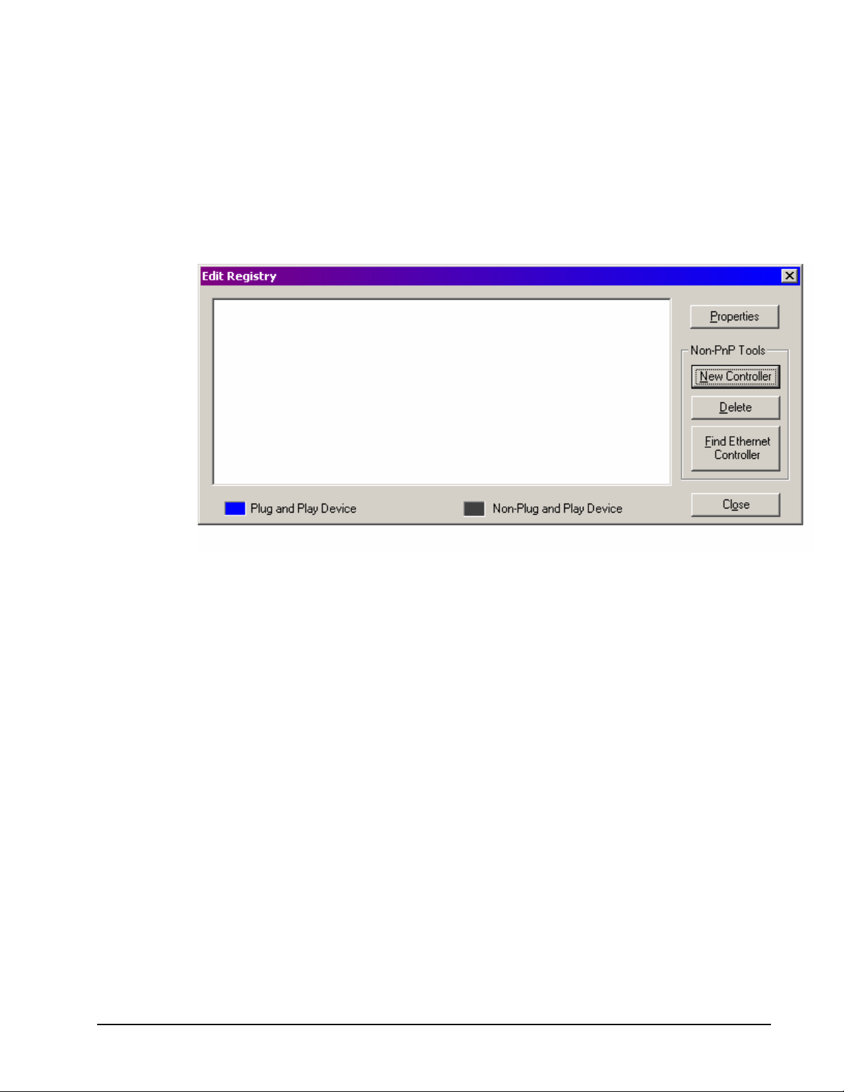
Galil software, such as WSDK or DMCSmartTerm.
The registry window is equipped with a button to Add a New Controller, change the Properties of an
existing controller, Delete a controller, or Find an Ethernet controller.
Use the New Controller button to add a new entry to the Registry. Use the Properties button to
change the properties of a current controller. For a new registration, you will need to supply the Galil
Controller type. The controller model number must be entered. If you are changing an existing
controller, this field will already have an entry. Pressing the down arrow to the right of this field will
reveal a menu of valid controller types. Once the DMC-3425 has been selected, there is a choice for
either Serial or Ethernet communication, as shown below. Select Serial communication.
DMC-3425 Chapter 2 Getting Started• 13
Page 22
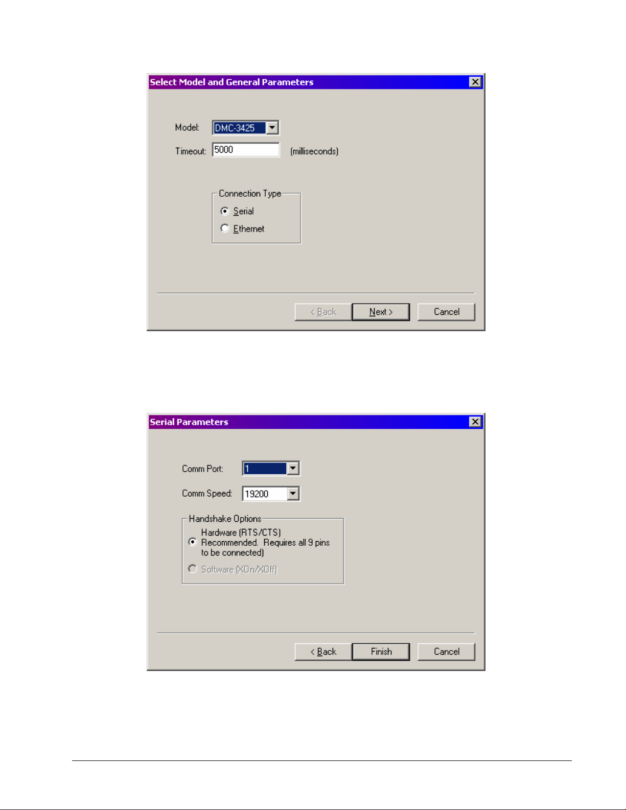
After selecting Next, the registry information will show a default Comm Port of 1 and a default Comm
Speed of 19200 appears. This information should be changed as necessary to reflect the computers
Comm Port and the baud rate set by the controller's baud rate jumpers.
Once you have set the appropriate Registry information for your controller, Select Finish and close the
registry window. You will now be able to communicate with the DMC-3425. Within WSDK, select
File and Connect to Controller. Within DMCSmartTerm, select Tools and Select Controller. Once
14 • Chapter 2 Getting Started DMC-3425
Page 23

the entry has been selected, click on the OK button. If the software has successfully established
communications with the controller, the registry entry will be displayed at the top of the screen.
If you are not properly communicating with the controller, the program will pause for 3-15 seconds.
The top of the screen will display the message “Status: not connected with Galil motion controller” and
the following error will appear: “STOP - Unable to establish communication with the Galil controller.
A time-out occurred while waiting for a response from the Galil controller.” If this message appears,
you must click OK. In this case, there is most likely an incorrect setting of the serial communications
port. The user must ensure that the correct communication port and baud rate are specified when
attempting to communicate with the controller. Please note that the serial port on the controller must
be set for handshake mode for proper communication with Galil software. The user must also insure
that the proper straight-through serial cable is being used (no Null modem). See appendix for the
correct pin-outs for the serial cable.
Once you establish communications, click on the menu for terminal and you will receive a colon
prompt. Communicating with the controller is described in later sections.
Using Non-Galil Communication Software
The DMC-3425 serial port is configured as DATASET. Your computer or terminal must be
configured as a DATATERM for full duplex, no parity, 8 data bits, one start bit and one stop bit.
Check to insure that the baud rate switches have been set to the desired baud rate as described above.
Your computer needs to be configured as a "dumb" terminal that sends ASCII characters as they are
typed to the DMC-3425. Use the EO command to specify if the characters should be echoed back
from the controller.
Sending Test Commands to the Terminal:
After you connect your terminal, press <carriage return> or the <enter> key on your keyboard. In
response to carriage return (CR), the controller responds with a colon, :
Now type
TPA (CR)
This command directs the controller to return the current position of the A axis. The controller should
respond with a number such as
0000000
Communicating through the Ethernet
For Ethernet communication, connect the DMC-3425 to your computer or to a hub. If connecting
through a switch or a hub, a standard RJ45 Ethernet cable is used. If connecting directly to the PC, a
cross-over RJ45 Ethernet cable must be used.
Using Galil Software for Windows
The controller must be registered in the Galil Windows registry for the host computer to communicate
with it. The registry may be accessed via Galil software, such as WSDK or DMCSmartTerm.
From WSDK, the registry is accessed under the FILE menu. From DMCSmartTerm it is accessed
under the Tools and Controller Registration menu. In the Galil Registry, the DMC-3425 can either
be added manually with the New Controller button or the software can automatically try to find the
controller with the Find Ethernet Controller button.
The first registry option is to use the New Controller button. The DMC-3425 should be selected from
the models listed, with Ethernet selected as the mode of communication.
DMC-3425 Chapter 2 Getting Started• 15
Page 24
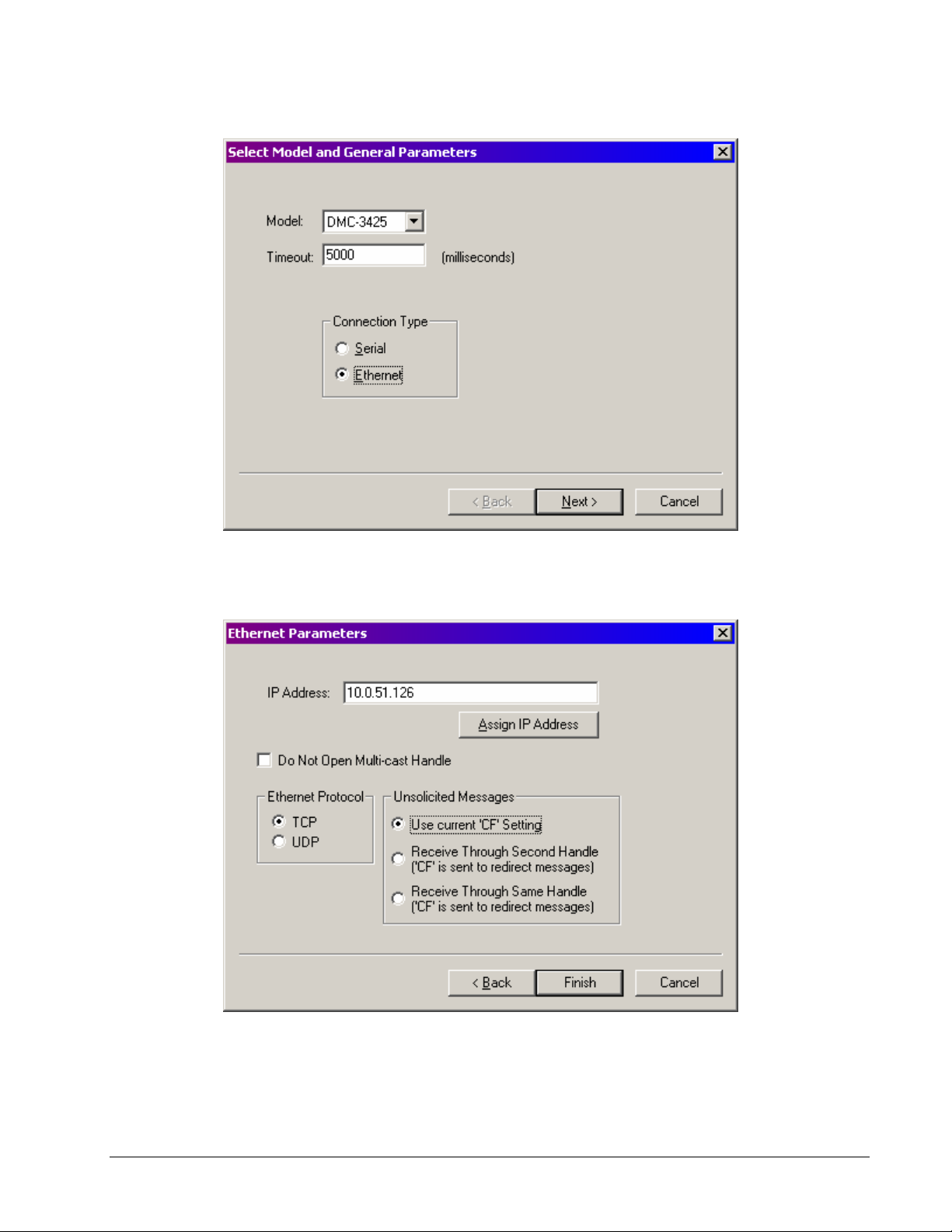
After Next is pressed, the next screen will allow the IP address to be selected and assigned.
Enter the IP address obtained from your system administrator into the box IP Address. Select the
button corresponding to the protocol in which you wish to communicate with the controller, UDP or
TCP. If the IP address has not been already assigned to the controller, click on ASSIGN IP
ADDRESS.
16 • Chapter 2 Getting Started DMC-3425
Page 25

ASSIGN IP ADDRESS will check the controllers that are linked to the network to see which ones do
not have an IP address. The program will then ask you whether you would like to assign the IP
address you entered to the controller with the specified serial number. Click on YES to assign it, NO
to move to next controller, or CANCEL to not save the changes. If there are no controllers on the
network that do not have an IP address assigned, the program will state this. Once the correct
controller has been selected, click on Finish.
If an IP address has already been assigned to the controller through the serial port and the IA
command, add this address to the IP Address box and then select Finish.
The second method for registering the controller is by using the option within the registry labeled Find
Ethernet Controllers. This utility uses the DMCNet software program to search for any controllers
on the network, both with and without IP addresses. If the DMC-3425 does not have an IP address, the
utility will listen for the BOOTP packet and then ask for an IP address to be assigned. Once the IP
address is added, click on Register and the controller will be added to the Galil Registry. If an IP
address has already been assigned to the controller, the utility will list that controller with its current IP
address. At this point, click on Register and the controller will be added to the Galil Registry.
Once you have set the appropriate Registry information for your controller, Select Close to close the
registry window. You will now be able to communicate with the DMC-3425. Within WSDK, select
File and Connect to Controller. Within DMCSmartTerm, select Tools and Select Controller. Once
the appropriate entry has been selected, click on the OK button. If the software has successfully
established communications with the controller, the registry entry will be displayed at the top of the
screen.
See Chapter 4 Communication for additional information on the Ethernet configuration and
connection.
Sending Test Commands to the Terminal:
After you connect your terminal, press <return> or the <enter> key on your keyboard. In response to
carriage return <return>, the controller responds with a colon, :
Now type
TPA <return>
This command directs the controller to return the current position of the A axis. The controller should
respond with a number such as
0000000
Step 6. Set-up axis for sinusoidal commutation (optional)
* This step is only required when the controller will be used to control a brushless motor with
sinusoidal commutation. Please consult the factory before operating with sinusoidal commutation.
The command BA is used to specify sinusoidal commutation mode for the DMC-3415 or DMC-3425.
In this mode the controller will output two sinusoidal phases for the DACs. Once specified, follow the
procedure outlined in Step 8b.
Step 7. Make connections to amplifier and encoder
Once you have established communications between the software and the DMC-3425, you are ready to
connect the rest of the motion control system. The motion control system generally consists of an
ICM-1460 Interface Module, a servo amplifier, and a motor to transform the current from the servo
amplifier into torque for motion. Galil also offers the AMP-1460 Interface Module which is an ICM1460 equipped with a servo amplifier for a DC motor.
DMC-3425 Chapter 2 Getting Started• 17
Page 26

A signal breakout board of some type is strongly recommended. If you are using a breakout board
from a third party, consult the documentation for that board to insure proper system connection.
If you are using the ICM-1460 or AMP-1460 with the DMC-3425, connect the 37-pin cable between
the controller and interconnect module.
Here are the first steps for connecting a motion control system:
Step A. Connect the motor to the amplifier with no connection to the controller. Consult the
amplifier documentation for instructions regarding proper connections. Connect and
turn on the amplifier power supply. If the amplifiers are operating properly, the
motor should stand still even when the amplifiers are powered up.
Step B. Connect the amplifier enable signal. Before making any connections from the
amplifier to the controller, you need to verify that the ground level of the amplifier is
either floating or at the same potential as earth.
Note: If you are using a DMC-3425-Stepper, the amplifier enable signal is used for
the second stepper output.
WARNING: When the amplifier ground is not isolated from the power line or when it has a different potential
than that of the computer ground, serious damage may result to the computer controller and amplifier.
If you are not sure about the potential of the ground levels, connect the two ground
signals (amplifier ground and earth) by a 10 kΩ resistor and measure the voltage
across the resistor. Only if the voltage is zero, proceed to connect the two ground
signals directly.
The amplifier enable signal is used by the controller to disable the motor. This
signal is labeled AMPEN on the ICM-1460 and should be connected to the enable
signal on the amplifier. Note that many amplifiers designate this signal as the
INHIBIT signal. Use the command, MO, to disable the motor amplifiers - check to
insure that the motor amplifiers have been disabled (often this is indicated by an
LED on the amplifier).
This signal changes under the following conditions: the watchdog timer activates,
the motor-off command, MO, is given, or the OE1 command (Enable Off-On-Error)
is given and the position error exceeds the error limit. As shown in Figure 3.1, AEN
can be used to disable the amplifier for these conditions.
The standard configuration of the AEN signal is TTL active high. In other words,
the AEN signal will be high when the controller expects the amplifier to be enabled.
The polarity and the amplitude can be changed if you are using the ICM-1460
interface board. To change the polarity from active high (5 volts = enable, zero volts
= disable) to active low (zero volts = enable, 5 volts = disable), replace the 7407 IC
with a 7406. Note that many amplifiers designate the enable input as ‘inhibit’.
To change the voltage level of the AEN signal, note the state of the JP1 jumper on
the ICM-1460. When the jumper is placed across 5V and AEN, the output voltage is
0-5V. To change to 12 volts, pull the jumper and rotate it so that +12V is connected
to AEN. If you remove the jumper, the output signal is an open collector, allowing
the user to connect an external supply with voltages up to 24V.
Step C. Connect the encoders
For stepper motor operation, an encoder is optional.
For servo motor operation, if you have a preferred definition of the forward and
reverse directions, make sure that the encoder wiring is consistent with that
definition.
18 • Chapter 2 Getting Started DMC-3425
Page 27

The DMC-3425 accepts single-ended or differential encoder feedback with or
without an index pulse. If you are not using the AMP-1460 or the ICM-1460, you
will need to consult the appendix for the encoder pinouts for connection to the
motion controller. The AMP-1460 and the ICM-1460 can accept encoder feedback
from a 10-pin ribbon cable or individual signal leads. For a 10-pin ribbon cable
encoder, connect the cable to the protected header connector labeled JP2. For
individual wires, simply match the leads from the encoder you are using to the
encoder feedback inputs on the interconnect board. The signal leads are labeled
CHA, CHB, and INDEX. These labels represent channel A, channel B, and the
INDEX pulse, respectively. For differential encoders, the complement signals are
labeled CHA-, CHB-, and INDEX-.
Note: When using pulse and direction encoders, the pulse signal is connected to
CHA and the direction signal is connected to CHB. The controller must be
configured for pulse and direction with the command CE. See the command
summary for further information on the command CE.
Step D. Verify proper encoder operation.
Once the encoder is connected as described above, turn the motor shaft and
interrogate the position with the instruction TP <return>. The controller response
will vary as the motor is turned.
At this point, if TP does not vary with encoder rotation, there are three possibilities:
1. The encoder connections are incorrect - check the wiring as necessary.
2. The encoder has failed - using an oscilloscope, observe the encoder signals.
Verify that both channels A and B have a peak magnitude between 5 and 12
volts. Note that if only one encoder channel fails, the position reporting varies
by one count only. If the encoder failed, replace the encoder. If you cannot
observe the encoder signals, try a different encoder.
3. There is a hardware failure in the controller - connect the same encoder to a
different axis. If the problem disappears, you probably have a hardware failure.
Consult the factory for help.
Step E. Connect Hall Sensors if available (sinusoidal commutation only)
Please consult factory before operating with sinusoidal commutation. Hall sensors
are only used with sinusoidal commutation on the DMC-3415 or DMC-3425 and are
not necessary for proper operation. The use of hall sensors allows the controller to
automatically estimate the commutation phase upon reset and also provides the
controller the ability to set a more precise commutation phase. Without hall sensors,
the commutation phase must be determined manually.
The Hall effect sensors are connected to the digital inputs of the controller. These
inputs can be used with the general-purpose inputs (bits 1 - 7). If you are using the
DMC-3425, only the first 3 inputs are available for general purpose.
Each set of inputs must use inputs that are in consecutive order. The input lines are
specified with the command, BI. For example, if the Hall sensors are connected to
inputs 1, 2 and 3, use the instruction:
BI1 <CR>
Step 8a. Connect Standard Servo Motor
The following discussion applies to connecting the DMC-3425 controller to standard servo motor
amplifiers:
DMC-3425 Chapter 2 Getting Started• 19
Page 28

The motor and the amplifier may be configured in the torque or the velocity mode. In the torque
mode, the amplifier gain should be such that a 10 Volt signal generates the maximum required current.
In the velocity mode, a command signal of 10 Volts should run the motor at the maximum required
speed.
Step by step directions on servo system setup are also included on the WSDK (Windows Servo Design
Kit) software offered by Galil. See section on WSDK for more details.
Check the Polarity of the Feedback Loop
It is assumed that the motor and amplifier are connected together and that the encoder is operating
correctly (Step D). Before connecting the motor amplifiers to the controller, read the following
discussion on setting Error Limits and Torque Limits.
Step A. Set the Error Limit as a Safety Precaution
Usually, there is uncertainty about the correct polarity of the feedback. The wrong
polarity causes the motor to run away from the starting position. Using a terminal
program, such as DMCSmartTerm, the following parameters can be given to avoid
system damage:
Input the commands:
ER 2000,2000 <CR> Sets error limit to be 2000 counts
OE 1,1 <CR> Disables amplifier when excess error exists
If the motor runs away and creates a position error of 2000 counts, the motor
amplifier will be disabled.
Note: This function requires the AEN signal to be connected from the controller to
the amplifier.
Step B. Setting Torque Limit as a Safety Precaution
To limit the maximum voltage signal to your amplifier, the DMC-3425 controller has
a torque limit command, TL. This command sets the maximum voltage output of the
controller and can be used to avoid excessive torque or speed when initially setting
up a servo system.
When operating an amplifier in torque mode, the voltage output of the controller will
be directly related to the torque output of the motor. The user is responsible for
determining this relationship using the documentation of the motor and amplifier.
The torque limit can be set to a value that will limit the motors output torque.
When operating an amplifier in velocity or voltage mode, the voltage output of the
controller will be directly related to the velocity of the motor. The user is responsible
for determining this relationship using the documentation of the motor and amplifier.
The torque limit can be set to a value that will limit the speed of the motor.
For example, the following command will limit the output of the controller to 1 volt:
TL 1 <CR> Sets torque limit to 1 Volt on A axis
Note: Once the correct polarity of the feedback loop has been determined, the torque
limit should, in general, be increased to the default value of 9.99. The servo will not
operate properly if the torque limit is below the normal operating range. See
description of TL in the command reference.
Step C. Disable motor
Issue the motor off command to disable the motor.
MO <CR> Turns motor off
Step D. Connecting the Motor
20 • Chapter 2 Getting Started DMC-3425
Page 29

Once the parameters have been set, connect the analog motor command signal
(ACMD) to the amplifier input.
Issue the servo here command to turn the motors on. To test the polarity of the
feedback, command a move with the instruction:
SH <CR> Servo Here to turn motors on
PR 1000 <CR> Position relative 1000 counts
BG <CR> Begin motion
When the polarity of the feedback is wrong, the motor will attempt to run away. The
controller should disable the motor when the position error exceeds 2000 counts. In
this case, the polarity of the loop must be inverted.
Inverting the Loop Polarity
When the polarity of the feedback is incorrect, the user must invert the loop polarity and this may be
accomplished by several methods. If you are driving a brush-type DC motor, the simplest way is to
invert the two motor wires (typically red and black). For example, switch the M1 and M2 connections
going from your amplifier to the motor. When driving a brushless motor, the polarity reversal may be
done with the encoder. If you are using a single-ended encoder, interchange the signal CHA and CHB.
If, on the other hand, you are using a differential encoder, interchange only CHA+ and CHA-. The
loop polarity and encoder polarity can also be affected through software with the MT, and CE
commands. For more details on the MT command or the CE command, see the Command Reference
section.
Sometimes the feedback polarity is correct (the motor does not attempt to run away) but the direction
of motion is reversed with respect to the commanded motion. If this is the case, reverse the motor
leads AND the encoder signals.
If the motor moves in the required direction but stops short of the target, it is most likely due to
insufficient torque output from the motor command signal ACMD. This can be alleviated by reducing
system friction on the motors. The instruction:
TT <CR> Tell torque
reports the level of the output signal. It will show a non-zero value that is below the friction level.
Once you have established that you have closed the loop with the correct polarity, you can move on to
the compensation phase (servo system tuning) to adjust the PID filter parameters, KP, KD and KI. It is
necessary to accurately tune your servo system to ensure fidelity of position and minimize motion
oscillation as described in the next section.
DMC-3425 Chapter 2 Getting Started• 21
Page 30
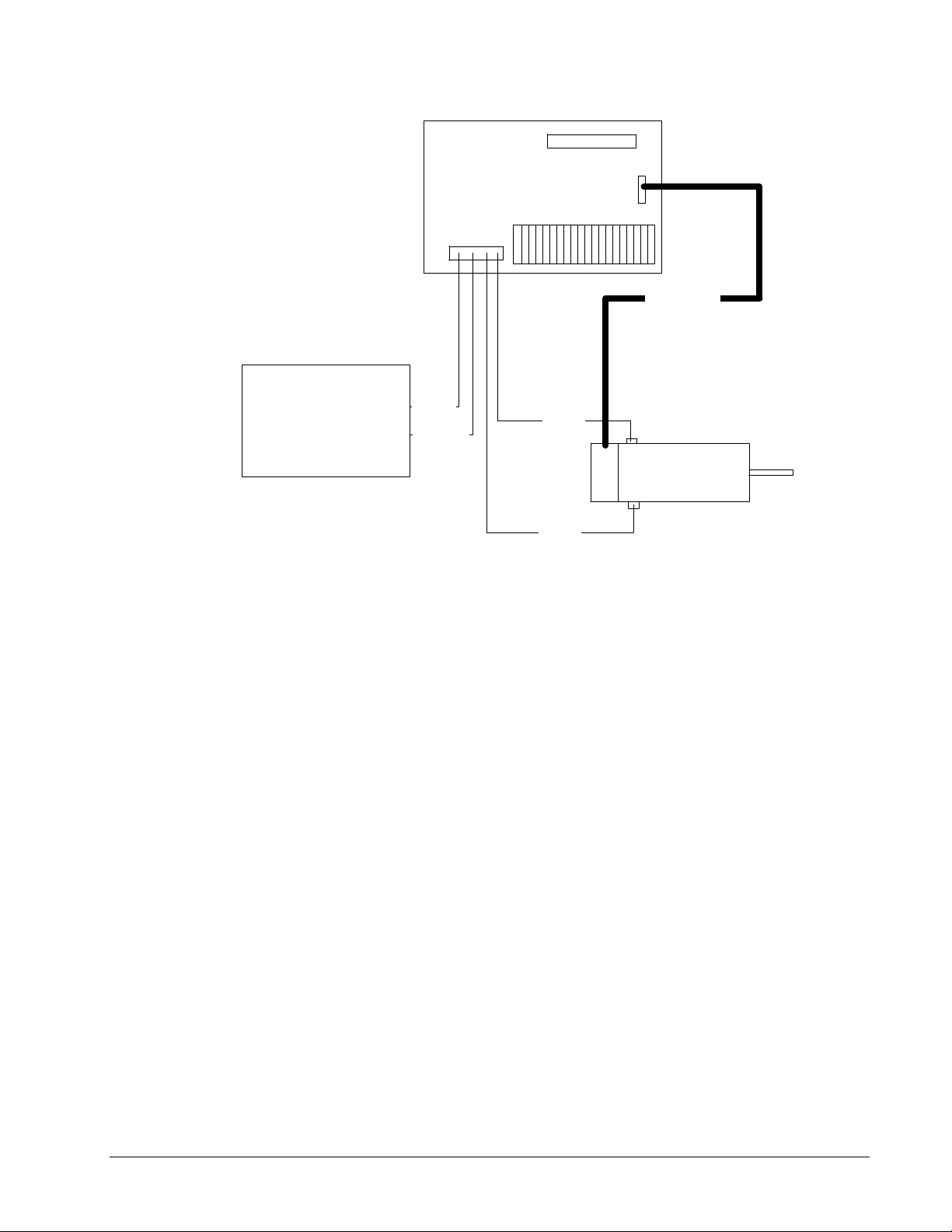
J2
ICM-1460
Encoder lines
Power Supply
VAMP+
AMPGND
Motor 1
Motor
Motor 2
Figure 2.3 - System Connections with the AMP-1460 Amplifier
22 • Chapter 2 Getting Started DMC-3425
Page 31

ICM-1460
GND
ACMD
AMPEN
Red Wire
Black Wire
Description Connection
Channel A+ MA+
Channel B+ MB+
Channel A- MAChannel B- MBIndex - IIndex + I+
Gnd GND
+5V 5V
Red Connector
Black Connector
11 INHIBIT
4 +REF IN
2 SIGNALGND
Figure 2.4 - System Connections with a separate amplifier (MSA 12-80). This diagram shows the
connections for a standard DC Servo Motor and encoder.
Step 8b. Connect brushless motor for sinusoidal commutation
Please consult the factory before operating with sinusoidal commutation. Any controller within
the distributed system may be configured for sinusoidal commutation. If a DMC-3415 is used, the
second DAC is simply initiated with the BA command. If a DMC-3425 is used, it will control only a
single brushless motor, but will take up two axes in configuration. When using sinusoidal
commutation, the parameters for the commutation must be determined and saved in the controller’s
non-volatile memory. The servo can then be tuned as described in Step 9.
Step A. Disable the motor amplifier
Use the command, MO, to disable the motor amplifiers.
Step B. Connect the motor amplifier to the controller.
The sinusoidal commutation amplifier requires 2 signals, usually denoted as Phase A
and Phase B. These inputs should be connected to the two sinusoidal signals
DMC-3425 Chapter 2 Getting Started• 23
Page 32

generated by the controller. The first signal is the main controller motor output,
ACMD. The second signal utilizes the second DAC on the controller and is brought
out on the ICM-1460 at pin 38 (ACMD2).
st
It is not necessary to be concerned with cross-wiring the 1
and 2nd signals. If this
wiring is incorrect, the setup procedure will alert the user (Step D).
Step C. Specify the Size of the Magnetic Cycle.
Use the command, BM, to specify the size of the brushless motors magnetic cycle in
encoder counts. For example, if you are using a linear motor where the magnetic
cycle length is 62 mm, and the encoder resolution is 1 micron, the cycle equals
62,000 counts. This can be commanded with the command:
BM 62000 <CR>
On the other hand, if you are using a rotary motor with 4000 counts per revolution
and 3 magnetic cycles per revolution (three pole pairs) the command is:
BM 1333.333 <CR>
Step D. Test the Polarity of the DACs and Hall Sensor Configuration.
Use the brushless motor setup command, BS, to test the polarity of the output DACs.
This command applies a certain voltage, V, to each phase for some time T, and
checks to see if the motion is in the correct direction.
The user must specify the value for V and T. For example, the command:
BS 2,700 <CR>
will test the brushless axis with a voltage of 2 volts, applying it for 700 milliseconds
for each phase. In response, this test indicates whether the DAC wiring is correct and
will indicate an approximate value of BM. If the wiring is correct, the approximate
value for BM will agree with the value used in the previous step.
Note: In order to properly conduct the brushless setup, the motor must be allowed to
move a minimum of one magnetic cycle in both directions.
Note: When using Galil Windows software, the timeout must be set to a minimum of
10 seconds (time-out = 10000) when executing the BS command. This allows the
software to retrieve all messages returned from the controller.
If Hall Sensors are Available:
Since the Hall sensors are connected randomly, it is very likely that they are wired in
the incorrect order. The brushless setup command indicates the correct wiring of the
Hall sensors. The hall sensor wires should be re-configured to reflect the results of
this test.
The setup command also reports the position offset of the hall transition point and the
zero phase of the motor commutation. The zero transition of the Hall sensors
typically occurs at 0°, 30° or 90° of the phase commutation. It is necessary to
inform the controller about the offset of the Hall sensor and this is done with the
instruction, BB.
Step E. Save Brushless Motor Configuration
It is very important to save the brushless motor configuration in non-volatile
memory. After the motor wiring and setup parameters have been properly
configured, the burn command, BN, should be given.
24 • Chapter 2 Getting Started DMC-3425
Page 33

If Hall Sensors are Not Available:
Without hall sensors, the controller will not be able to estimate the commutation
phase of the brushless motor. In this case, the controller could become unstable until
the commutation phase has been set using the BZ command (see next step). It is
highly recommended that the motor off command be given before executing the BN
command. In this case, the motor will be disabled upon power up or reset and the
commutation phase can be set before enabling the motor.
Step F. Set Zero Commutation Phase
When an axis has been defined as sinusoidally commutated, the controller must have
an estimate for commutation phase. When hall sensors are used, the controller
automatically estimates this value upon reset of the controller. If no hall sensors are
used, the controller will not be able to make this estimate and the commutation phase
must be set before enabling the motor.
If Hall Sensors are Not Available:
To initialize the commutation without Hall effect sensor use the command, BZ. This
function drives the motor to a position where the commutation phase is zero, and sets
the phase to zero.
The BZ command argument is a real number that represents the voltage to be applied
to the amplifier during the initialization. When the voltage is specified by a positive
number, the initialization process will end up in the motor off (MO) state. A
negative number causes the process to end in the Servo Here (SH) state.
Warning: This command must move the motor to find the zero commutation phase.
This movement is instantaneous and will cause the system to jerk. Larger applied
voltages will cause more severe motor jerk. The applied voltage will typically be
sufficient for proper operation of the BZ command. For systems with significant
friction, this voltage may need to be increased and for systems with very small
motors, this value should be decreased.
For example,
BZ -2 <CR>
will drive the axis to zero, using a 2V signal. The controller will then leave the
motor enabled. For systems that have external forces working against the motor,
such as gravity, the BZ argument must provide a torque 10x the external force. If the
torque is not sufficient, the commutation zero may not be accurate.
If Hall Sensors are Available:
The estimated value of the commutation phase is good to within 30°. This estimate
can be used to drive the motor but a more accurate estimate is needed for efficient
motor operation. There are 3 possible methods for commutation phase initialization:
Method 1. Use the BZ command as described above.
Method 2. Drive the motor close to commutation phase of zero and then use BZ
command. This method decreases the amount of system jerk by moving the motor
close to zero commutation phase before executing the BZ command. The controller
makes an estimate for the number of encoder counts between the current position and
the position of zero commutation phase. This value is stored in the operand _BZx.
Using this operand the controller can be commanded to move the motor. The BZ
command is then issued as described above. For example, to initialize the A axis
motor upon power or reset, the following commands may be given:
SH <CR> Enable A axis motor
DMC-3425 Chapter 2 Getting Started• 25
Page 34

PRA=-1*(_BZA) <CR> Move A motor close to zero commutation phase
BGA <CR> Begin motion on A axis
AMA<CR> Wait for motion to complete on A axis
BZA=-1 <CR> Drive motor to commutation phase zero and leave motor
on
Method 3. Use the command, BC. This command uses the hall transitions to
determine the commutation phase. Ideally, the hall sensor transitions will be
separated by exactly 60° and any deviation from 60° will affect the accuracy of this
method. If the hall sensors are accurate, this method is recommended. The BC
command monitors the hall sensors during a move and monitors the Hall sensors for
a transition point. When that occurs, the controller computes the commutation phase
and sets it. For example, to initialize the motor upon power or reset, the following
commands may be given:
SH <CR> Enable motor
BC <CR> Enable the brushless calibration command
PR 50000 <CR> Command a relative position movement
BG <CR> Begin motion. When the hall sensors detect a phase
transition, the commutation phase is re-set.
Step 8c. Connect Step Motors
In Stepper Motor operation, the pulse output signal has a 50% duty cycle. Step motors operate open
loop and do not require encoder feedback. When a stepper is used, the auxiliary encoder for the
corresponding axis is unavailable for an external connection. If an encoder is used for position
feedback, connect the encoder to the main encoder input corresponding to that axis. The commanded
position of the stepper can be interrogated with RP or DE. The encoder position can be interrogated
with TP. Only the DMC-3415 allows the use of the main encoder input with a stepper motor. The
DMC-3425 does not have this option.
The frequency of the step motor pulses can be smoothed with the filter parameter, KS. The KS
parameter has a range between 0.5 and 8, where 8 implies the largest amount of smoothing. See
Command Reference regarding KS.
The DMC-3425 profiler commands the step motor amplifier. All DMC-3425 motion commands apply
such as PR, PA, VP, CR and JG. The acceleration, deceleration, slew speed and smoothing are also
used. Since step motors run open-loop, the PID filter does not function and the position error is not
generated.
To connect step motors with the DMC-3425 you must follow this procedure:
Step A. Install SM jumper
Install the jumper SMX at location JP2 to enable stepper motor operation on the
DMC-3415. For the DMC-3425-Stepper, the jumpers should be loaded on SMX and
SMY. For a discussion of SM jumpers, see section “Step 2. Configuring Jumpers on
the DMC-3425”.
Step B. Connect step and direction signals from the controller to respective signals on your
step motor amplifier.
The DMC-3415 outputs STEPX (step) signals on the ICM-1460 terminal labeled
ACMD, and outputs DIRX (direction) signals on the ICM-1460 terminal labeled
ACMD2.
26 • Chapter 2 Getting Started DMC-3425
Page 35

The DMC-3425 outputs STEPY signals on the ICM-1460 terminal labeled ERROR,
and outputs DIRX on the ICM-1460 terminal labeled AMPEN. X-axis connections
are identical to the DMC-3415.
Consult the documentation for your step motor amplifier for proper connections.
Step C. Configure DMC-3425 for motor type using MT command. You can configure the
DMC-3425 for active high or active low pulses. Use the command MT 2 for active
high step motor pulses and MT -2 for active low step motor pulses. See description
of the MT command in the Command Reference.
Note: The DMC-3425 must be ordered as a DMC-3425-Stepper to drive two axes of stepper motors.
Step 9. Tune the Servo System
The system compensation provides fast and accurate response by adjusting the filter parameters. The
following presentation suggests a simple and easy way for compensation. More advanced design
methods are available with software design tools from Galil, such as the Windows Servo Design Kit
(WSDK software).
If the torque limit was set as a safety precaution in the previous step, you may want to increase this
value. See Step B of the above section “Setting Torque Limit as a Safety Precaution”
The filter has three parameters: the damping, KD; the proportional gain, KP; and the integrator, KI.
The parameters should be selected in this order.
To start, set the integrator to zero with the instruction
KI 0 <CR> Integrator gain
and set the proportional gain to a low value, such as
KP 1 <CR> Proportional gain
KD 100 <CR> Derivative gain
For more damping, you can increase KD (maximum is 4095). Increase gradually and stop after the
motor vibrates. A vibration is noticed by audible sound or by interrogation. If you send the command
TE <CR> Tell error
a few times, and get varying responses, especially with reversing polarity, it indicates system vibration.
When this happens, simply reduce KD.
Next you need to increase the value of KP gradually (maximum allowed is 1023). You can monitor the
improvement in the response with the Tell Error instruction
KP 10 <CR> Proportion gain
TE <CR> Tell error
As the proportional gain is increased, the error decreases.
Again, the system may vibrate if the gain is too high. In this case, reduce KP. Typically, KP should
not be greater than KD/4.
Finally, to select KI, start with zero value and increase it gradually. The integrator eliminates the
position error, resulting in improved accuracy. Therefore, the response to the instruction
TE <CR>
becomes zero. As KI is increased, its effect is amplified and it may lead to vibrations. If this occurs,
simply reduce KI.
For a more detailed description of the operation of the PID filter and/or servo system theory, see
Chapter 10 Theory of Operation.
DMC-3425 Chapter 2 Getting Started• 27
Page 36

Step 10. Configure the Distributed Control System
The final step in Getting Started with the DMC-3425 distributed control system is to configure the
individual controllers as their respective axes in the system. For more information on the operation of
distributed control, please refer to Chapter 4.
Configuring Operation for Distributed Control
There are two methods for configuring a distributed control system; an automatic mode or a manual
mode. The automatic mode uses a single command (HC) to configure all the slaves in a particular
system. This command uses the BOOTP packets from the slaves, along with configuration jumpers, to
automatically select IP addresses and set up the system. In the manual mode, slave controllers are
assigned IP addresses and then configured into axes through various software commands. Both
methods are outlined below.
Automatic Configuration of D istributed Control
The automatic method of assigning a distributed control network uses the HC command to indicate
number of axes, type of communication and update rate of a system. This command also configures
the number of IOC extended I/O modules in the system, if any.
The data update rate specifies the rate at which each slave sends a data packet to the master containing
current status information. The data records are used by the master controller to make decisions based
on the status of the slave controllers or IOC-7007 modules. This data record rate may be selected
manually with the QW command, but will be set automatically by the second field of the HC
command.
The data contained in the record is as follows:
reference position
encoder position
position error
velocity
torque
limit and home switches
axis status (in motion, motor off, at speed, stopcode)
uncommitted inputs
uncommitted outputs
user defined variables (4)
In order for the HC command to be initiated, an IP address must already be assigned to the master. See
Step 5 “Establishing Communication between the DMC-3425 and the host PC” for information on
addressing the master controller. The slaves, in this method, will typically remain without IP
addresses. If the slaves are to be addressed manually while still using the HC mode, skip to the next
section Manual Slave IP configuratio n wi th HC c om ma n d.
Once initiated, the master controller will ARP for slaves with IP address already assigned, and then
‘listen’ for BOOTP packets from the slave controllers without IP addresses. As it receives these
packets, the master will configure the slave axes according to jumpers set on each slave controller.
Once this connection has been established, the master will initiate QW, or data records, to begin from
each slave for status updates.
The full procedure for this method is as follows:
28 • Chapter 2 Getting Started DMC-3425
Page 37

Step 1. Assign IP address to master controller either through IA command or through
BOOTP utility in the Galil Software Registry. You may then burn this IP address
into the master with the BN in order to keep this address during resets.
Step 2. Place jumpers on each slave controller indicating which slave corresponds to which
axes in the system. See section “Step 2. Configuring Jumpers on the DMC-3425”.
Step 3. Determine total number of axes, data update rate, and number of IOC-7007
controllers in the distributed system.
Step 4. Issue the command HCn,m,o,p where n is the total number of axes, m is the data
update rate in milliseconds, o is a 1 for UDP communication or 2 for TCP/IP
communication and p is the total number of IOC-7007’s in the system. When using
UDP communication, the HC command will assign one handle for both commands
and QW records. When using TCP/IP communication, the HC command will assign
one handle for commands and one handle for QW records. If o is a 3, then TCP/IP is
used for commands, and UDP is used for QW records.
Step 5. Poll the operand _HC for success of connection. A response of 1 indicates the
command is currently executing, a 2 for a successful configuration and a 0 for a
failed configuration or no HC issued.
NOTE: The HC command may take up to 20 seconds to complete due to the time involved in waiting
for the BOOTP packets.
Manual Slave IP configuration with HC command
It may be desired to manually assign an IP address to the slaves, while still using the HC command to
connect to these slaves. This is possible, but you will need to take into account the addressing scheme
the HC command is using, and you must install axis configuration jumpers according to “Step 2.
Configuring jumpers on the DMC-3425”.
When the HC command is initiated, the master will ARP addresses where it expects slave controllers
to reside. If no controllers respond to the ARPs, the master will then ‘listen’ for the BOOTP packets
from un-assigned slave controllers.
For addressing the slaves manually, the IP address MUST be assigned as follows. This will insure that
the HC command will properly configure these controllers based on the master IP address.
Assume Master IP address = m.n.o.p where m, n, o and p is a valid Ethernet IP address.
First Slave IP address (Axis B or C) = m.n.o.p+2
Next slave is assigned +2 if previous slave was a single axis (DMC-3415).
Next slave is assigned +4 if previous slave was a dual axis (DMC-3425).
Slave axes are always assigned addresses based on their first axis.
IOC-7007 controllers are addressed as follows:
IOC 1 = m.n.o.p+16
IOC 2 = m.n.o.p+20
For example, in a 5 axis/1 IOC-7007 system with a DMC-3415 A axis Master, a DMC-3415
B axis, a DMC-3425 CD axis and a DMC-3415 E axis the following IP addresses would
be set:
Assume Master IP address – 10.10.50.10
B Axis DMC-3415 – 10.10.50.12
CD Axis DMC-3425 – 10.10.50.14
E Axis DMC-3415 – 10.10.50.18
DMC-3425 Chapter 2 Getting Started• 29
Page 38

IOC-7007 (1) – 10.10.50.26
Automatic Configuration Example
The example below shows a typical setup file for the DMC-3425 distributed control system using the
automatic configuration. This example is for a UDP system, with one handle used per slave. The IP
addresses of the slaves are unassigned, as this is the simplest way for the slave controllers to be
configured. The IP address of the master needs to have been assigned as described in Step 5
“Establishing Communication between the DMC-3425 and the host PC”. The HC command will
automatically assign those IP addresses based on the axis jumper settings described in Chapter 2.
Instruction Interpretation
#SETUP Begin Program
HC=6,20,1,0
#LOOP; JP#LOOP,_HC=1
IF (_HC=0) Test for HC success. 0 = failed while 2 = success.
MG”CONFIGURATION FAILED”
ELSE
MG”CONFIG SUCCESS”
ENDIF
EN
Automatic configuration for a 6 axis UDP system with 20 msec
update rate. The final 0 indicates no IOC-7007 Ethernet I/O
modules in the system.
Wait while automatic configuration operates. This could take
up to 10+ seconds.
Manual Configuration of Distributed Control
For the manual configuration of distributed control, each 3425 must be assigned an IP address. This
can be done with the BOOTP procedure in the Galil software or the IA command can be used to assign
the IP address through the serial port. Once the IP address has been assigned, a BN command should
be issued to save this value in the controller’s non-volatile memory. Since all configuration is done
manually in this method, there is no limit for the IP address of each slave in the system.
Upon power-up or reset, the master 3425 must establish each slave connection. The following steps
must be taken while connected to the master 3425:
1. Using the IH command, open handles for each slave. For a TCP/IP connection, each
slave controller must have 2 open handles, one for commands from the master, the other
for data returned from the slave (QW). The second internet handle for each slave
controller must contain a specific port value. The value must be an even number greater
than 502. For a UDP connection, a slave controller can use a single handle for both
commands from the master as well as data returned from the slave. The command for
opening the communication handle is:
IHh=ip0,ip1,ip2,ip3<p>n h is the handle. ip is the slave IP address. <p specifies
port number. >n specifies connection type, 1 for UDP or 2 for TCP/IP.
2. Set the total number of axes in the system with the NA command. For example, assume
there are 2 DMC-3425 slave cards, therefore there will be 6 axes (2 in the master and 4 in
the slaves) and the command would be NA6.
3. Connect each slave handle to the master. This is accomplished with the CH command.
The format of this command is:
CHa=h1,h2 where a is the first axis designator of the slave controller, h1 is the
handle for commands and h2 is the handle for slave status. h1 may equal h2 in a
UDP setup.
30 • Chapter 2 Getting Started DMC-3425
Page 39

Note that only one of the 2 axes (per DMC-3425) needs to be assigned with the CH command.
4. In order for the Master controller to be able to make decisions based on the status of the
slave/server controllers, it is necessary for the slaves to generate data records giving their
current status. The record is sent at a rate set by the QW command. The QW command
must be executed by the master before the slave can issue a record under any method.
The format of the command is
QWh=n where h is the handle. n is a number between 4 and 16000.
n sets the number of samples (msec with default TM1000).
n equal to 0 disables the mode.
The data contained in the record is as follows:
reference position
encoder position
position error
velocity
torque
limit and home switches
axis status (in motion, motor off, at speed, stopcode)
uncommitted inputs
uncommitted outputs
user defined variables (4)
Manual Configuration Example
The example below shows a typical setup file for the DMC-3425 distributed control system in manual
mode. This example is for a TCP/IP system, with two handles used per slave. The IP address of the
first slave (Axes C and D) is 160.50.10.1, while the address of the second slave (Axes E and F) is
160.50.10.2. Note that in the two axis setup, different port numbers are used for the second handle to
the same IP address.
Instruction Interpretation
#SETUP Begin Program
IHD=160,50,10,1>2 Set handle D (for commands) to slave 1's IP
IHE=160,50,10,1<510>2 Open handle E for slave 1's data record
IHF=160,50,10,2>2 Set handle F (for commands) to slave 2’s IP
IHG=160,50,10,2<512>2 Open handle G for slave 2's data record
NA6 6 axis total
CHC=D,E Axis C & D assigned to slave 1 (Handle D,E)
CHE=F,G Axis E & F assigned to slave 2 (Handle F,G)
QWE=20 Handle E sends data record every 20 msec
QWG=20 Handle G sends data record every 20 msec
EN
Note: This program is the minimum necessary for manually setting up the controller. An actual
application program should make use of error and status checking. An example would be testing the
operand _IHh2 for successful handle connections. See Command Reference for more details.
DMC-3425 Chapter 2 Getting Started• 31
Page 40

Design Examples
Here are a few examples for tuning and using your controller. These examples are shown for a single axis system
only, but can be modified to test up to 8 axes within a distributed control network. See Chapter 6
Programming Motion for more examples of multi-axis programming.
Example 1 - System Set-up
This example assigns the system filter parameters, error limits and enables the automatic error shut-off.
Instruction
KP 10 Set proportional gain
KD 100 Set damping
KI 1 Set integral
OE 1 Set error off
ER 1000 Set error limit
Example 2 - Profiled Move
Interpretation
Objective: Rotate a distance of 10,000 counts at a slew speed of 20,000 counts/sec and an acceleration
and deceleration rates of 100,000 counts/s
Instruction
PR 10000 Distance
SP 20000 Speed
DC 100000 Deceleration
AC 100000 Acceleration
BGA Start Motion
In response, the motor turns and stops.
Interpretation
2
.
Example 3 - Position Interrogation
The position of the A axis may be interrogated with the instruction
TPA Tell position
which returns the position of the main encoder.
The position error, which is the difference between the commanded position and the actual position
can be interrogated by the instructions
TEA Tell error
Example 4 - Absolute Position
Objective: Command motion by specifying the absolute position.
Instruction
DP 0 Define the current position as 0
PA 7000 Sets the desired absolute position
BGA Start motion on A axis
32 • Chapter 2 Getting Started DMC-3425
Interpretation
Page 41

Example 5 - Velocity Control (Jogging)
Objective: Drive the motor at specified speeds.
Instruction
JG 10000 Set Jog Speed
AC 100000 Set acceleration
DC 50000 Set deceleration
BGA Start motion on A axis
Interpretation
after a few seconds, command:
JG –40000 New speed and Direction
TVA Returns speed
This causes velocity changes including direction reversal. The motion can be stopped with the
instruction
STA Stop
Example 6 - Operation Under Torque Limit
The magnitude of the motor command may be limited independently by the instruction TL. The
following program illustrates that effect.
Instruction
TL 0.2 Set output limit to 0.2 volts
JG 10000 Set speed
BGA Start motion on A axis
Interpretation
The motor will probably not move as the output signal is not sufficient to overcome the friction. If the
motion starts, it can be stopped easily by a touch of a finger.
Increase the torque level gradually by instructions such as
TL 1.0 Increase torque limit to 1 volt.
TL 9.98 Increase torque limit to maximum, 9.98 Volts.
The maximum level of 10 volts provides the full output torque.
Example 7 - Interrogation
The values of the parameters may be interrogated using a ?. For example, the instruction
KP ? Return gain
The same procedure applies to other parameters such as KI, KD, FA, etc.
Example 8 - Operation in the Buffer Mode
The instructions may be buffered before execution as shown below.
Instruction
PR 600000 Distance
SP 10000 Speed
WT 10000 Wait 10000 milliseconds before reading the next instruction
BGA Start the motion
Interpretation
DMC-3425 Chapter 2 Getting Started• 33
Page 42

Example 9 - Motion Programs
Motion programs may be edited and stored in the memory. They may be executed at a later time.
The instruction
ED Edit mode
moves the operation to the editor mode where the program may be written and edited. For example, in
response to the first ED command, the Galil Windows software will open a simple editor window.
From this window, the user can type in the following program:
#A Define label
PR 700 Distance
SP 2000 Speed
BGA Start motion
EN End program
This program can be downloaded to the controller by selecting the File menu option download. Once
this is done, close the editor.
Now the program may be executed with the command
XQ #A Start the program running
Example 10 - Motion Programs with Loops
Motion programs may include conditional jumps as shown below.
Instruction
#A Label
DP 0 Define current position as zero
V1=1000 Set initial value of V1
#Loop Label for loop
PA V1 Move motor V1 counts
BGA Start motion
AMA After motion is complete
WT 500 Wait 500 ms
TPA Tell position
V1=V1+1000 Increase the value of V1
JP #Loop,V1<10001 Repeat if V1<10001
EN End
Interpretation
After the above program is entered, download the program from the File menu and exit the Editor. To
start the motion, command:
XQ #A Execute Program #A
Example 11- Motion Programs with Trippoints
The motion programs may include trippoints as shown below.
Instruction
#B Label
DP0 Define initial position
PR 30000 Set target
34 • Chapter 2 Getting Started DMC-3425
Interpretation
Page 43

SP 5000 Set speed
BGA Start motion
AD 4000 Wait until A moved 4000
TPA Tell position
EN End program
To start the program, command:
XQ #B Execute Program #B
Example 12 - Control Variables
Objective: To show how control variables may be utilized.
Instruction
#A;DP0 Label; Define current position as zero
PR 4000 Initial position
SP 2000 Set speed
BGA Move
AMA Wait until move is complete
WT 500 Wait 500 ms
#B
V1 = _TP Determine distance to zero
PR –V1/2 Command move 1/2 the distance
BGA Start motion
AMA After motion
WT 500 Wait 500 ms
V1= Report the value of V1
JP #C, V1=0 Exit if position=0
JP #B Repeat otherwise
#C;EN End
Interpretation
To start the program, command
XQ #A Execute Program #A
This program moves the motor to an initial position of 4000 and returns it to zero on increments of half
the distance. Note, _TP is an internal variable that returns the value of the position. Internal variables
may be created by preceding a DMC-3425 instruction with an underscore, _.
Example 13 - Control Variables and Offset
Objective: Illustrate the use of variables in iterative loops and use of multiple instructions on one line.
Instruction
#A Set initial values
KI0
DP0
V1=8; V2=0 Initializing variables to be used by program
#B Program label #B
OF V1 Set offset value
WT 200 Wait 200 msec
DMC-3425 Chapter 2 Getting Started• 35
Interpretation
Page 44

V2=_TP Set variable V2 to the current position
JP#C,@ABS[V2]<2 Exit if error small
MG V2 Report value of V2
V1=V1-1 Decrease Offset
JP #B Return to top of program
#C;EN End
This program starts with a large offset and gradually decreases its value, resulting in decreasing error.
36 • Chapter 2 Getting Started DMC-3425
Page 45

Chapter 3 Connecting Hardware
Overview
The DMC-3425 provides digital inputs for A and B forward limit, A and B reverse limit, A and B
home input and abort input. The controller also has 3 uncommitted, TTL inputs, 3 TTL outputs
and 2 analog inputs (12-bit).
The DMC-3415 provides a forward and reverse limit, home input and abort input. The controller also
has 7 uncommitted, TTL inputs, 3 TTL outputs and 2 analog inputs (12-bit).
This chapter describes the inputs and outputs and their proper connection.
Using Inputs
Limit Switch Input
The forward limit switch (FLSx) inhibits motion in the forward direction immediately upon activation
of the switch. The reverse limit switch (RLSx) inhibits motion in the reverse direction immediately
upon activation of the switch. If a limit switch is activated during motion, the controller will make a
decelerated stop using the deceleration rate previously set with the DC command. The motor will
remain on (in a servo state) after the limit switch has been activated and will hold motor position. To
set the activation state of the limit switches refer to the command CN, configure, in the Command
Reference.
When a forward or reverse limit switch is activated, the current application program that is running
will be interrupted and the controller will automatically jump to the #LIMSWI subroutine if one exists.
This is a subroutine that the user can include in any motion control program and is useful for executing
specific instructions upon activation of a limit switch.
After a limit switch has been activated, further motion in the direction of the limit switch will not be
possible until the logic state of the switch returns back to an inactive state. This usually involves
physically opening the tripped switch. Any attempt at further motion before the logic state has been
reset will result in the following error: “022 - Begin not possible due to limit switch” error.
The operands, _LFx and _LRx, return the state of the forward and reverse limit switches, respectively
(x represents the axis, A or B). The value of the operand is either a ‘0’ or ‘1’ corresponding to the
logic state of the limit switch, active or inactive, respectively. If the limit switches are configured for
active low, no connection or a 5V input will be read as a ‘0’, while grounding the switch will return a
‘1’. If the limit switches are configured for active high, the reading will be inverted and no connection
or a 5V input will be read as a ‘1’, while grounding the switch will return a ‘0’.
Using a terminal program, the state of a limit switch can be printed to the screen with the command,
MG _LFx or MG _LRx. This prints the value of the limit switch operands for the 'x' axis. The logic
DMC-3425 Chapter 3 Connecting Hardware• 37
Page 46

state of the limit switches can also be interrogated with the TS command. For more details on TS,
_LFx, _LRx, or MG see the Command Reference.
Home Switch Input
Homing inputs are designed to provide mechanical reference points for a motion control application.
A transition in the state of a Home input alerts the controller that a particular reference point has been
reached by a moving part in the motion control system. A reference point can be a point in space or an
encoder index pulse.
The Home input detects any transition in the state of the switch and changes between logic states 0 and
1, corresponding to either 0V or 5V depending on the configuration set by the user (CN command).
The CN command can be used to customize the homing routine to the user’s application.
There are three homing routines supported by the DMC-3425: Find Edge (FE), Find Index (FI), and
Standard Home (HM).
The Find Edge routine is initiated by the command sequence: FEx <return>, BGx <return> (where x
could be any axis on the controller, A through H). The Find Edge routine will cause the motor to
accelerate then slew at constant speed until a transition is detected in the logic state of the Home input.
The direction of the FE motion is dependent on the state of the home switch. Refer to the CN
command to set the correspondence between the Home Input voltage and motion direction. The motor
will decelerate to a stop when a transition is seen on the input. The acceleration rate, deceleration rate
and slew speed are specified by the user, prior to the movement, using the commands AC, DC, and SP.
It is recommended that a high deceleration value be used so the motor will decelerate rapidly after
sensing the Home switch.
The Find Index routine is initiated by the command sequence: FIx <return>, BGx <return> (where x
could be any axis on the controller, A through H). Find Index will cause the motor to accelerate to
the user-defined slew speed (SP) at a rate specified by the user with the AC command and slew until
the controller senses a change in the index pulse signal from low to high. The motor then decelerates
to a stop at the rate previously specified by the user with the DC command. Although Find Index is an
option for homing, it is not dependent upon a transition in the logic state of the Home input, but instead
is dependent upon a transition in the level of the index pulse signal.
The Standard Homing routine is initiated by the sequence of commands HMx <return>, BGx <return>
(where x could be any axis on the controller, A through H). Standard Homing is a combination of
Find Edge and Find Index homing. Initiating the standard homing routine will cause the motor to slew
until a transition is detected in the logic state of the Home input. The motor will accelerate at the rate
specified by the command, AC, up to the slew speed. After detecting the transition in the logic state
on the Home Input, the motor will decelerate to a stop at the rate specified by the command DC. After
the motor has decelerated to a stop, it switches direction and approaches the transition point at the
speed of 256 counts/sec. When the logic state changes again, the motor moves forward (in the
direction of increasing encoder count) at the same speed, until the controller senses the index pulse.
After detection, it decelerates to a stop and defines this position as 0. The logic state of the Home input
can be interrogated with the command MG _HMA. This command returns a 0 or 1 if the logic state is
low or high (dependent on the CN command). The state of the Home input can also be interrogated
indirectly with the TS command.
For examples and further information about Homing, see command HM, FI, FE of the Command
Reference and the section entitled ‘Homing’ in the Programming Motion Section of this manual.
Abort Input
The function of the Abort input is to immediately stop the controller upon transition of the logic state.
NOTE: The response of the abort input is significantly different from the response of an activated
limit switch. When the abort input is activated, the controller stops generating motion commands
immediately, whereas the limit switch response causes the controller to make a decelerated stop.
38 • Chapter 3 Connecting Hardware DMC-3425
Page 47

NOTE: The effect of an Abort input is dependent on the state of the off-on-error function for each
axis. If the Off-On-Error function is enabled for any given axis, the motor for that axis will be turned
off when the abort signal is generated. This could cause the motor to ‘coast’ to a stop since it is no
longer under servo control. If the Off-On-Error function is disabled, the motor will decelerate to a stop
as fast as mechanically possible and the motor will remain in a servo state.
All motion programs that are currently running are terminated when a transition in the Abort input is
detected. For information on setting the Off-On-Error function, see the Command Reference, OE.
Uncommitted Digital Inputs
The general use inputs are TTL and are accessible through the ICM-1460 or AMP-1460 as IN1 – IN3
for the DMC-3425 and IN1 – IN7 for the DMC-3415. The inputs can be accessed directly from the 37
Pin-D cable or connector on the controller, also. For a description of the pinouts, consult the appendix.
These inputs can be interrogated with the use of the command TI (Tell Inputs), the operand _TI, the
function @IN[n] and the distributed I/O command TZ. All of these commands may be used locally to
address individual controllers, or globally through the distributed control network. See Chapter 4 for a
discussion of Global vs. Local communication as it pertains to I/O of the control system.
NOTE: For systems using the ICM-1460 or AMP-1460 interconnect module, there is an option to
provide opto-isolation on the inputs. In this case, the user provides an isolated power supply (+5V to
+24V and ground). For more information, see the section “Opto-Isolation Option for ICM-1460” in
the Appendix of this manual, or consult Galil.
Amplifier Interface
The DMC-3425 analog command voltage, ACMD, ranges between +/-10V. This signal, along with
GND, provides the input to the power amplifiers. The power amplifiers must be sized to drive the
motors and load. For best performance, the amplifiers should be configured for a current mode of
operation with no additional compensation. The gain should be set such that a 10 Volt input results in
the maximum required current. If the controller is operating in stepper mode, the pulse and direction
signals will be input into a stepper drive.
The DMC-3425 also provides an amplifier enable signal, AEN. This signal is activated under the
following conditions: the watchdog timer activates, the motor-off command, MO, is given, or the
OE1command (Enable Off-On-Error) is given and the position error exceeds the error limit. As
shown in Figure 3.1, AEN can be used to disable the amplifier for these conditions.
Note: For a controller ordered as a DMC-3425-Stepper, the amplifier enable signal is used for the
second stepper output.
The standard configuration of the AEN signal is TTL active high. In this configuration the AEN signal
will be high when the controller expects the amplifier to be enabled. The polarity and the amplitude
can be changed if you are using the ICM-1460 interface board. To change the polarity from active
high (5 volts= enable, zero volts = disable) to active low (zero volts = enable, 5 volts= disable), replace
the 7407 IC with a 7406. Note that many amplifiers designate the enable input as ‘inhibit’.
To change the voltage level of the AEN signal, note the state of the jumper on the ICM/AMP-1460.
When JP1 has a jumper from “AEN” to “5V” (default setting), the output voltage is 0-5V. To change
to 12 volts, pull the jumper out and rotate it so that it connects the pins marked “AEN” and “+12V”. If
the jumper is removed entirely, the output is an open collector, allowing the user to connect an external
supply with voltages up to 24V.
To connect an external 24V supply, remove the jumper JP1 from the interconnect board. Connect a
2.2kΩ resistor in series between the +24V of the supply and the amplifier enable terminal on the
interconnect (AMPEN). Then wire the AMPEN to the enable pin on the amplifier. Connect the -24V
DMC-3425 Chapter 3 Connecting Hardware• 39
Page 48

to the ground, GND, of the interconnect and connect the GND of the interconnect to the GND of the
amplifier.
DMC-3425
7407 Open Collector
Buffer. The Enable signal
can be inverted by using
a 7406.
37 - 40
Pin Cable
ICM-1460
+5V+12V
Connection to +5V or +12V made through
jumper location JP1. Removing the jumper
allows the user to connect their own supply to
the desired voltage level (Up to24V).
AMPEN
GND
ACMD
Analog Switch
SERVO
MOTOR
AMPLIFIER
Figure 3.1 - Connecting AEN to the motor amplifier
TTL Inputs
As previously mentioned, the DMC-3425 has 3 uncommitted TTL level inputs while the DMC-3415
has 7 uncommitted TTL level inputs. The command @IN, TI and TZ will read the state of the inputs.
For more information on these commands refer to the Command Reference.
The reset input is also a TTL level, non-isolated signal and is used to locally reset the DMC-3425
without resetting the PC.
Analog Inputs
The DMC-3425 has 2 analog inputs configured for the range between –10V and +10V. The inputs are
decoded by a 12-bit ADC giving a voltage resolution of approximately .005V. The impedance of these
inputs is 10Kohms. The analog inputs may be read using the @AN[n] function, where n is the number
of the analog input to be read.
40 • Chapter 3 Connecting Hardware DMC-3425
Page 49

TTL Outputs
The DMC-3425 provides three general use outputs, an output compare and 4 status LED’s.
The general use outputs are TTL and are accessible through the ICM-1460 as OUT1 thru OUT3.
These outputs can be turned On and Off with the commands SB (Set Bit), CB (Clear Bit), OB (Output
Bit) and OP (Output Port). For more information about these commands, see the Command Reference.
The value of the outputs can be checked with the operand _OP, the function @OUT[] and the
distributed control command TZ. Chapter 4 contains more information with regards to I/O in the
distributed control network.
The output compare signal is TTL and is available on the ICM-1460 as CMP. Output compare is
controlled by the position of any of the main encoders on the controller. The output can be
programmed to produce an active low pulse (1usec) based on an incremental encoder value or to
activate once when an axis position has been passed. For further information, see the command OC in
the Command Reference.
Note: For a controller ordered as a DMC-3425-Stepper, the Error output is taken for the second
stepper motor output.
There are four status LEDs on the controller, which indicate operating and error conditions on the
controller. Below is a list of those LEDs and their functions.
Green Power LED - The green status LED indicates that the +5V power has been applied properly to
Red Status/Error LED - The red error LED will flash on initially at power up, and stay lit for
the controller.
approximately 1 – 8 seconds. After this initial power up condition, the LED will illuminate
for the following reasons:
1. At least one axis has a position error greater than the error limit. The error limit is set by
using the command ER.
2. The reset line on the controller is held low or is being affected by noise.
3. There is a failure on the controller and the processor is resetting itself.
4. There is a failure with the output IC which drives the error signal.
Green Link LED – The second green LED is lit when there is an Ethernet connection to the
controller. This LED tests only for the physical connection, not for an active or enabled link.
Yellow Activity LED – The yellow LED indicates traffic across the Ethernet connection. This LED
will show both transmit and receive activity across the connection. If there is no Ethernet
connection or IP address assigned, the LED will flash at regular intervals to show that the
BOOTP packets are being broadcast.
Note: For systems using the ICM-1460 or AMP-1460 interconnect module, there is an option to
provide opto-isolation for the outputs. In this case, the user provides an isolated power supply
(+5V to +24V and ground). For more information, see the section “Opto-Isolation Option for
ICM-1460” in the Appendix of this manual, or contact Galil.
DMC-3425 Chapter 3 Connecting Hardware• 41
Page 50

THIS PAGE LEFT BLANK INTENTIONALLY
42 • Chapter 3 Connecting Hardware DMC-3425
Page 51

Chapter 4 Communication
Introduction
The DMC-3425 has one RS232 port and one Ethernet port. The RS-232 port is the data set. The
Ethernet port is a 10Base-T link. The RS-232 is a standard serial link with communication baud rates
up to 19.2kbaud.
For initial setup, Galil recommends starting with the RS-232 interface. The RS-232 provides a
simplified interface that minimizes the potential problems for first time setup. Once the configuration
parameters have been properly set and saved on the controller, the Ethernet communication should be
established.
RS232 Port
The DMC-3425 has a single RS232 connection for sending and receiving commands from a PC or
other terminal. The pin-outs for the RS232 connection are as follows.
RS232 - Port 1 DATATERM
RS-232 Configuration
Configure your PC for 8-bit data, one start-bit, one stop-bit, full duplex and no parity. The baud rate
for the RS232 communication can be selected by selecting the proper jumper configuration on the
DMC-3425 according to the table below.
1 CTS – output 6 CTS – output
2 Transmit Data - output 7 RTS – input
3 Receive Data - input 8 CTS – output
4 RTS – input 9 No connect (Can connect to +5V or sample clock)
5 Ground
Baud Rate Selection
JUMPER SETTINGS BAUD RATE
96 12 --
OFF OFF 19200
ON OFF 9600
DMC-3425 Chapter 4 Communication• 43
Page 52

OFF ON 1200
Handshaking Modes
The RS232 port is configured for hardware handshaking. In this mode, the RTS and CTS lines are
used. The CTS line will go high whenever the DMC-3425 is not ready to receive additional
characters. The RTS line will inhibit the DMC-3425 from sending additional characters. Note: The
RTS line goes high for inhibit. This handshake procedure ensures proper communication especially at
higher baud rates.
Ethernet Configuration
Communication Protocols
The Ethernet is a local area network through which information is transferred in units known as
packets. Communication protocols are necessary to dictate how these packets are sent and received.
The DMC-3425 supports two industry standard protocols, TCP/IP and UDP/IP. The controller will
automatically respond in the format in which it is contacted.
TCP/IP is a "connection" protocol. The master must be connected to the slave in order to begin
communicating. Each packet sent is acknowledged when received. If no acknowledgement is
received, the information is assumed lost and is resent.
Unlike TCP/IP, UDP does not require a "connection". This protocol is similar to communicating via
RS232. If information is lost, the controller does not return a colon or question mark. Because the
protocol does not provide for lost information, the sender must re-send the packet.
Ethernet communication transfers information in ‘packets’. The packets must be limited to 470 data
bytes or less. Larger packets could cause the controller to lose communication.
NOTE: In order not to lose information in transit, Galil recommends that the user wait for an
acknowledgement of receipt of a packet before sending the next packet.
Addressing
There are three levels of addresses that define Ethernet devices. The first is the Ethernet or hardware
address. This is a unique and permanent 6 byte number. No other device will have the same Ethernet
address. The DMC-3425 Ethernet address is set by the factory and the last two bytes of the address are
the serial number of the controller.
The second level of addressing is the IP address. This is a 32-bit (or 4 byte) number. The IP address is
constrained by each local network and must be assigned locally. Assigning an IP address to the
controller can be done in a number of ways.
The first method is to use the BOOT-P utility via the Ethernet connection (the DMC-3425 must be
connected to network and powered). For a brief explanation of BOOT-P, see the section: Third Party
Software. Either a BOOT-P server on the internal network or the Galil terminal software may be used.
To use the Galil BOOT-P utility, select the registry in the terminal emulator. Next, select the DMC-
3425 controller communicating via Ethernet from the software registry. Once the controller has been
selected, the next screen shows options for the actual connection. Enter the IP address at the prompt
and select either TCP/IP or UDP/IP as the protocol. When done, click on the ASSIGN IP ADDRESS.
The Galil Terminal Software will respond with a list of all controllers on the network that do not
currently have IP addresses. The user selects the controller and the software will assign the controller
the specified IP address. Then enter the terminal and type in BN to save the IP address to the
controller's non-volatile memory. A full description of addressing the card may be found in Chapter 2
Getting Started.
44 • Chapter 4 Communication DMC-3425
Page 53

CAUTION: Be sure that there is only one BOOT-P server running. If your network has DHCP or BOOT-P
running, it may automatically assign an IP address to the controller upon linking it to the network. In order to
ensure that the IP address is correct, please contact your system administrator before connecting the controller
to the Ethernet network.
The second method for setting an IP address is to send the IA command through the DMC-3425 main
RS-232 port. The IP address you want to assign may be entered as a 4 byte number delimited by
commas (industry standard uses periods) or a signed 32 bit number. (Ex. IA 124,51,29,31 or IA
2083724575) Type in BN to save the IP address to the controller's non-volatile memory.
NOTE: Galil strongly recommends that the IP address selected is not one that can be accessed across
the Gateway. The Gateway is an application that controls communication between an internal network
and the outside world.
The third level of Ethernet addressing is the UDP or TCP port number. The Galil controller does not
require a specific port number. The port number is established by the client or master each time it
connects to the controller.
Ethernet Handles
An Ethernet handle is a communication resource within a device. The DMC-3425 can have a
maximum of 8 Ethernet handles open at any time. When using TCP/IP, each connection to a device,
such as the host computer, requires an individual Ethernet handle. In UDP/IP, one handle may be used
for all the masters, but each slave uses one. (Pings and ARP's do not occupy handles.) If all 8 handles
are in use and a 9
error in its windows application.
th
master tries to connect, it will be sent a "reset packet" that generates the appropriate
The TH command may be used to indicate which handles are currently connected to and which are
currently free.
Global vs. Local Operation
Each DMC-3425 controls two axes of motion, referred to as A and B. The host computer can
communicate directly with any DMC-3425 using an Ethernet or RS-232 connection. When the host
computer is directly communicating with any DMC-3425, all commands refer to the first two axes as
A and B. Direct communication with the DMC-3425 is known as LOCAL OPERATION.
The concept of Local and Global Operation also applies to application programming. See Chapter 7:
Global vs. Local Programming.
DMC-3425 Chapter 4 Communication• 45
Page 54

LOCAL OPERATION
Host Computer
RS-232
or
Ethernet
DMC-3425
A and B
Axes
DMC-3425
A and B
Axes
DMC-3425
A and B
Axes
DMC-3425
A and B
Axes
The DMC-3425 supports Galil’s Distributed Control System. This allows up to 4 DMC-3425s to be
connected together as a single virtual 8-axis controller. In this system, one of the controllers is
designated as the master. The master can receive commands from the host computer that apply to all
of the axes in the system.
A simple way to view Local and Global Operation: When the host communicates with a slave
controller, it considers the slave as a 2-axis controller. When the host communicates with a master, it
considers the master as a multi-axis controller. Similarly, an application program residing in a slave
controller deals only with 2 motors as A & B. An application program in a master deals with all
motors referenced as A through H.
GLOBAL OPERATION
Host Computer
RS-232
or
Ethernet
DMC-3425
A and B
Axes
Ethernet
DMC-3425
C and D
Axes
DMC-3425
E and F
Axes
DMC-3425
G and H
Axes
The controllers may operate under both Local and/or Global Mode. In general, operating in Global
Mode simplifies controlling the entire system. However, Local Mode operation is necessary in some
46 • Chapter 4 Communication DMC-3425
Page 55

situations; using Local Mode for setup and testing is useful since this isolates the controller. Specific
modes of motion require operation in Local Mode. Also, each controller can have a program,
including the slave controllers. When a slave controller has a program, this program would always
operate in Local Mode.
Operation of Distributed Control
For most commands it is not necessary to be conscious of whether an axis is local or remote. For
instance to set the KP value for the A and C axes, the command to the master would be
KP 10,,20
Similarly, the interrogation commands can also be issued. For example, the position error for all axes
would be TE. The position operand for the F axis would be_TPF.
Some commands inherently are sent to all controllers. These include commands such as AB (abort),
CN and TM. In addition, the * may be used to send commands to all controllers. For example
SP*=1000
will send a speed of 1000 cts/sec to all axes. This syntax may be used with any configuration or
parameter commands.
Certain commands need to be launched specifically. For this purpose there is the SA command. In its
simplest form the SA command is
SAh= "command string"
Here "command string" will be sent to handle h. For example, the SA command is the means for
sending an XQ command to a slave/server. A more flexible form of the command is
SAh= field1,field2,field3,field4 ... field8
where each field can be a string in quotes or a variable.
For example, to send the command KI,,5,10; Assume var1=5 and var2=10 and send the command:
SAF= "KI",var1,var2
When the Master/client sends an SA command to a Slave/server, it is possible for the master to
determine the status of the command. The response _IHh4 will return the number 1 to 4. One means
waiting for the acknowledgement from the slave. Two means a colon (command accepted) has been
received. Three means a question mark (command rejected) has been received. Four means the
command timed out.
If a command generates responses (such as the TE command), the values will be stored in _SAh0 thru
_SAh7. If a field is unused its _SA value will be -2^31.
Accessing the I/O of the Slaves
The I/O of the server/slaves is settable and readable from the master. The bit numbers are adjusted by
the handle number of the slave controller. Each handle adds 100 to the bit number. Handle A is 100
and handle H is 800. In a TCP/IP control setup with two handles per slave, Galil recommends using
the value of the first handle for simplicity. In a UDP system, the single handle per slave is used to
address the I/O.
The command TZ can be used to display all of the digital I/O contained in a distributed control system.
Any IOC-7007’s configured using the HC command will also be displayed with the TZ command. See
the Command Reference for more information on the TZ command.
DMC-3425 Chapter 4 Communication• 47
Page 56

Digital Outputs
For outputs, the SB and CB commands are used to command individual output ports, while the OP
command is used for setting bytes of data. The SB and CB commands may be set globally through the
master, while the OP command must be sent to the slave using the SA command.
Outputs may be set globally according to the following numbering scheme: Bitnum = (Slave Handle *
100) + Output Bit. For example:
Set Bit 2 on a UDP distributed slave using the E handle for communication. The E handle would have
a numerical value of 500, plus the bit number of 2. The command would therefore become SB502.
Specific outputs in a distributed system may be read by using the @OUT[n] function, where n is the
corresponding bit number as defined above.
Output bits on an IOC-7007 may also be set through the master controller in a distributed network.
Please refer to the IOC-7007 Manual for information on setting and reading these I/O points.
Digital Inputs
Digital inputs may be addressed individually using the @IN[n] function, or in blocks using the TI
command. Both of these commands may be sent globally to the controller. The ‘n’ in the @IN[n]
function operates identically to the SB/CB syntax. This means that a specific input bit is referenced as
the slave handle number * 100 plus the input bit. For example:
Read input bit 4 on a TCP/IP distributed slave using the C handle for communication. The C handle in
this case would give a value of 300. Therefore, to read bit 4, the command would be MG@IN[304].
The MG in this case simply displays this data to the terminal.
The TI command may be used to read all inputs on a slave in blocks of 8. This is helpful if the slave
controller in question has a DB-14064 expanded I/O daughter card. The TI command uses the slave
handle number * 100 plus the block number to be read. The block number is only used if the
controller has the DB-14064 expansion option.
Inputs on an IOC-7007 may also be read through the master controller in a distributed network. Please
refer to the IOC-7007 Manual for information on setting and reading these points.
Analog Inputs
Each DMC-3425 controller has two 12-bit analog inputs. These inputs are read with the command
@AN[n], where n is the input to be read. The master controller has n = 1 and 2, the first slave
controller uses n = 3 and 4, etc.
Handling Communication Errors
A new automatic subroutine which is identified by the label #TCPERR, has been added. If a controller
has an application program running and the TCP or UDP communication is lost, the #TCPERR routine
will automatically execute. The #TCPERR routine should be ended with a RE command. In the UDP
configuration, the QW commands must be active in order for the #TCPERR routine on the master to
operate properly.
Multicasting
A multicast may only be used in UDP and is similar to a broadcast, (where everyone on the network
gets the information) but specific to a group. In other words, all devices within a specified group will
receive the information that is sent in a multicast. There can be many multicast groups on a network
and are differentiated by their multicast IP address. To communicate with all the devices in a specific
multicast group, the information can be sent to the multicast IP address rather than to each individual
device IP address. All Galil controllers belong to a default multicast address of 239.255.19.56. The
controller's multicast IP address can be changed by using the IA> u command.
48 • Chapter 4 Communication DMC-3425
Page 57

The Galil Registry has an option to disable the opening of the multicast handle on the DMC-3425. By
default this multicast handle will be opened.
Unsolicited Message Handling
Anytime a controller generates an internal response from a program, generates an internal error or
sends a message from a program using the MG command, this is termed an unsolicited message.
There are two software commands that will configure how the controller handles these messages; the
CW and the CF command.
The DMC-3425 has 8 Ethernet handles as well as 1 serial port where unsolicited messages may be
sent. The CF command is used to configure the controller to send these messages to specific ports. In
addition, the Galil Registry has various options for sending this CF command. For more information,
see the CF command in the DMC-3425 Command Reference. The MG can also send the message to a
specific handle using the MG{Eh} syntax, where h is the handle. See the MG command in the
Command Reference for more information.
The CW command has two data fields that affect unsolicited messages. The first field configures the
most significant bit (MSB) of the message. A value of 1 will set the MSB of unsolicited messages,
while a value of 2 suppresses the MSB. The majority of software programs use a setting of CW2,
although the Galil Smart Terminal and WSDK will set this to CW1 for internal usage. If you have
difficulty receiving characters from the controller, or receive garbage characters instead of messages,
check the status of the CW command for a setting of CW2.
IOC-7007 Support
The IOC-7007 is an Intelligent Ethernet I/O controller that can be programmed in standard Galil
language. This module allows various configurations of TTL inputs, opto-isolated inputs, high power
outputs and relay switches to be used in the Galil distributed motion system. Each IOC-7007 may be
populated by up to seven IOM I/O modules.
The IOC-7007 Ethernet I/O controller may be used in a distributed system and commanded by the
master controller. The HC command is used to specify total number of IOC-7007 controllers within
that distributed system. Once configured, the I/O of that IOC-7007 becomes incorporated in the
distributed system, much the same as board level I/O of the DMC-3425 slaves.
Inputs of the IOC-7007 are read using the standard @IN[n] and TI commands as follows:
@IN[n] where n is the IOC-7007 input bit to be read. n is calculated with the equation n =
(HandleNum * 1000) + BitNum. HandleNum is the numeric value of the IOC-7007 handle (1 – 8)
while BitNum is the specific bit number on the IOC to be read.
TIn where n is the IOC-7007 input slot to be read. n is calculated with the equation n =
(HandleNum * 1000) + SlotNum. Again, HandleNum is the numeric value of the IOC-7007 handle (1
– 8). SlotNum corresponds to the location of the IOM input module in the 7 slots of the IOC-7007 (0 –
6). This will return either an 8 bit or 16 bit decimal value depending on which IOM input module is
being used.
Outputs of the IOC-7007 are set and cleared using the standard SB and CB commands, as well as with
the OQ and OB commands. Outputs can be read with the @OUT[n] command. These commands
operate as follows:
SBn or CBn where n is the IOC-7007 output to be set or cleared. n is calculated identically to
the @IN[n] configuration, with n = (HandleNum * 1000) + BitNum.
@OUT[n] where n is the IOC-7007 output to be read. This uses the same n configuration as
SB and CB.
OQn,m where n is the IOC-7007 output location and m is the data to be written. Specifically,
n = (HandleNum * 1000) + SlotNum where HandleNum is the numeric value of the IOC-7007 handle
DMC-3425 Chapter 4 Communication• 49
Page 58

(1 – 8) and SlotNum is the slot number of the IOM output module to be written to (0 – 6). m is the
decimal representation of the data written to the 4 (0 – 15) or 8 (0 – 255) output points of the IOM
module.
Please refer to the IOC-7007 manual for complete information on how to configure, read and write
information to the IOC-7007 Ethernet I/O module.
Modbus Support
The Modbus protocol supports communication between masters and slaves. The masters may be
multiple PC's that send commands to the controller. The slaves are typically peripheral I/O devices
that receive commands from the controller.
When the Galil controller acts as the master, the IH command is used to assign handles and connect to
its slaves. The IP address may be entered as a 4 byte number separated with commas (industry
standard uses periods) or as a signed 32 bit number. A port number may also be specified, and should
be set to 502, which is the Modbus defined port number. The protocol (TCP/IP or UDP/IP) to use
must also be designated at this time. Otherwise, the controller will not connect to the slave. (Ex.
IHB=151,25,255,9<502>2 - This will open handle #2 and connect to the IP address 151.25.255.9, port
502, using TCP/IP)
An additional protocol layer is available for speaking to I/O devices. Modbus is an RS-485 protocol
that packages information in binary packets that are sent as part of a TCP/IP packet. In this protocol,
each slave has a 1 byte slave address. The DMC-3425 can use a specific slave address or default to the
handle number.
The Modbus protocol has a set of commands called function codes. The DMC-3425 supports the 10
major function codes:
Function Code Definition
01 Read Coil Status (Read Bits)
02 Read Input Status (Read Bits)
03 Read Holding Registers (Read Words)
04 Read Input Registers (Read Words)
05 Force Single Coil (Write One Bit)
06 Preset Single Register (Write One Word)
07 Read Exception Status (Read Error Code)
15 Force Multiple Coils (Write Multiple Bits)
16 Preset Multiple Registers (Write Words)
17 Report Slave ID
50 • Chapter 4 Communication DMC-3425
Page 59

The DMC-3425 provides three levels of Modbus communication. The first level allows the user to
create a raw packet and receive raw data. It uses the MBh command with a function code of –1. The
format of the command is
MBh = -1,len,array[] where len is the number of bytes
array[] is the array with the data
The second level incorporates the Modbus structure. This is necessary for sending configuration and
special commands to an I/O device. The formats vary depending on the function code that is called.
For more information refer to the Command Reference.
The third level of Modbus communication uses standard Galil commands. Once the slave has been
configured, the commands that may be used are @IN[], @AN[], SB, CB, OB, and AO. For example,
AO 2020,8.2 would tell I/O number 2020 to output 8.2 volts.
If a specific slave address is not necessary, the I/O number to be used can be calculated with the
following:
I/O Number = (HandleNum*1000) +((Module-1)*4) + (BitNum-1)
Where HandleNum is the handle number from 1 (A) to 8 (H). Module is the position of the module in
the rack from 1 to 16. BitNum is the I/O point in the module from 1 to 4.
If an explicit slave address is to be used, the equation becomes:
I/O Number = (SlaveAddress*10000) + (HandleNum*1000) +((Module-1)*4) + (Bitnum-1)
To view an example procedure for communicating with an OPTO-22 rack, refer to the appendix.
Other Communication Options
User Defined Ethernet Variables
It may be necessary within a distributed system to share information that is not contained as position,
torque, velocity or other control data. The DMC-3425 provides 2 user defined variables that are
passed as part of the QW record shared among the distributed system. In this way, it is not necessary
for a single controller to write variable data directly to all the other controllers in the system.
ZA and ZB are two user defined variables which are passed with the QW record at each update. Data
that is written to these variables is then seen by the master DMC-3425 in the system.
Handle Switching
By default, when initiating a communication session with a DMC-3425 controller, the first available
handle is used. If no handles have been assigned to the controller, the A handle is chosen. The
command HS allows the user to switch this connection to another handle, freeing up the initial handle
or trading with another currently used handle. Or, once handles have been defined, the HS command
may be used to switch handles to prioritize slave locations and I/O locations.
Handle Restore on Communication Failure
There are instances within an Ethernet system, whether UDP or TCP/IP, when a handle may become
disconnected without closing properly. An example of this would be a simple cable failure, where the
Ethernet cable of a certain slave becomes detached.
The command HR is used to enable a mode in which the master controller, upon seeing a failure on a
handle, will attempt to restore that handle. This is helpful when a distributed system is already fully
configured and a slave is lost. The #TCPERR routine can be used to flag the error, while the handle
restore will attempt to reconnect to the slave until the problem is fixed. This makes it unnecessary to
re-run the setup for the entire distributed system.
DMC-3425 Chapter 4 Communication• 51
Page 60

Note: This function is only available if the system has been configured using the automatic handle
configuration command, HC.
Waiting on Handle Responses
The operation of the distributed network has commands being sent to the master controller, which then
distributes these commands to the slave axes in the system. For example, the command
PR10,10,10,10,10,10,10,10 sent to the master becomes packets of PR10,10 sent by the master to each
of the slaves in the system. When the slave receives this command from the master, a colon or
question mark is generated and sent back to the master to acknowledge the command.
The HW command allows the user to select whether or not the master will wait on this colon response
from the slave. If the HW is set to 0, the master will not wait for these responses. This results in faster
command execution but could cause problems if any slave errors are generated. The setting HW1, on
the other hand, insures that the master knows of any slave errors but does result in a slightly increased
command execution time as it waits for these responses.
Data Record
The DMC-3425 can provide a block of status information with the use of a single command, QR. This
command, along with the QZ command can be very useful for accessing complete controller status.
The QR command will return 4 bytes of header information and specific blocks of information as
specified by the command arguments: QR ABCDEFGHS
Each argument corresponds to a block of information according to the Data Record Map below. If no
argument is given, the entire data record map will be returned. Note that the data record size will
depend on the number of axes.
NOTE: A, B, C, & D can be interchanged with X, Y, Z, & W respectively.
Data Record Map
DATA TYPE ITEM BLOCK
UB 1st byte of header Header
UB 2
UB 3
UB 4
UW sample number I block
UB general input bank 0 (Inputs 1-7) I block
UB general input bank 1 (Always 0) I block
UB general input bank 2 (DB-14064) I block
UB general input bank 3 (DB-14064) I block
UB general input bank 4 (DB-14064) I block
UB general input bank 5 (DB-14064) I block
UB general input bank 6 (DB-14064) I block
UB general input bank 7 (DB-14064) I block
UB general input bank 8 (DB-14064) I block
UB general input bank 9 (DB-14064) I block
UB general output bank 0 (Outputs 1 – 3) I block
UB general output bank 1 (Always 0) I block
nd
byte of header Header
rd
byte of header Header
rth
byte of header Header
52 • Chapter 4 Communication DMC-3425
Page 61

UB general output bank 2 (DB-14064) I block
UB general output bank 3 (DB-14064) I block
UB general output bank 4 (DB-14064) I block
UB general output bank 5 (DB-14064) I block
UB general output bank 6 (DB-14064) I block
UB general output bank 7 (DB-14064) I block
UB general output bank 8 (DB-14064) I block
UB general output bank 9 (DB-14064) I block
UB error code I block
UB general status I block
UW segment count of coordinated move for S plane S block
UW coordinated move status for S plane S block
SL distance traveled in coordinated move for S plane S block
UW 0 T block
UW 0 T block
SL 0 T block
UW A axis status A block
UB A axis switches A block
UB A axis stopcode A block
SL A axis reference position A block
SL A axis motor position A block
SL A axis position error A block
SL A axis auxiliary position A block
SL A axis velocity A block
SW A axis torque A block
SW Analog Input 1 A block
UW B axis status B block
UB B axis switches B block
UB B axis stopcode B block
SL B axis reference position B block
SL B axis motor position B block
SL B axis position error B block
SL B axis auxiliary position B block
SL B axis velocity B block
SW B axis torque B block
SW Analog Input 2 B block
UW C axis status C block
UB C axis switches C block
UB C axis stopcode C block
SL C axis reference position C block
SL C axis motor position C block
SL C axis position error C block
SL C axis auxiliary position C block
SL C axis velocity C block
SW C axis torque C block
DMC-3425 Chapter 4 Communication• 53
Page 62

SW C axis analog input C block
UW D axis status D block
UB D axis switches D block
UB D axis stopcode D block
SL D axis reference position D block
SL D axis motor position D block
SL D axis position error D block
SL D axis auxiliary position D block
SL D axis velocity D block
SW D axis torque D block
SW D axis analog input D block
UW E axis status E block
UB E axis switches E block
UB E axis stopcode E block
SL E axis reference position E block
SL E axis motor position E block
SL E axis position error E block
SL E axis auxiliary position E block
SL E axis velocity E block
SW E axis torque E block
SW E axis analog input E block
UW F axis status F block
UB F axis switches F block
UB F axis stopcode F block
SL F axis reference position F block
SL F axis motor position F block
SL F axis position error F block
SL F axis auxiliary position F block
SL F axis velocity F block
SW F axis torque F block
SW F axis analog input F block
UW G axis status G block
UB G axis switches G block
UB G axis stopcode G block
SL G axis reference position G block
SL G axis motor position G block
SL G axis position error G block
SL G axis auxiliary position G block
SL G axis velocity G block
SW G axis torque G block
SW G axis analog input G block
UW H axis status H block
UB H axis switches H block
UB H axis stopcode H block
SL H axis reference position H block
54 • Chapter 4 Communication DMC-3425
Page 63

SL H axis motor position H block
SL H axis position error H block
SL H axis auxiliary position H block
SL H axis velocity H block
SW H axis torque H block
SW H axis analog input H block
NOTE: UB = Unsigned Byte, UW = Unsigned Word, SW = Signed Word, SL = Signed Long Word
Explanation of Status Information and Axis Switch Information
Header Information - Byte 0, 1 of Header:
BIT 15 BIT 14 BIT 13 BIT 12 BIT 11 BIT 10 BIT 9 BIT 8
1 N/A N/A N/A N/A I Block
Present
in Data
Record
BIT 7 BIT 6 BIT 5 BIT 4 BIT 3 BIT 2 BIT 1 BIT 0
H Block
Present
in Data
Record
G Block
Present
in Data
Record
F Block
Present
in Data
Record
E Block
Present
in Data
Record
D Block
Present
in Data
Record
C Block
Present
in Data
Record
T Block
Present
in Data
Record
B Block
Present
in Data
Record
Bytes 2, 3 of Header:
Bytes 2 and 3 make a word that represents the Number of bytes in the data record, including the
header. Byte 2 is the low byte and byte 3 is the high byte
NOTE: The header information of the data records is formatted in little endian.
General Status Information (1 Byte)
BIT 7 BIT 6 BIT 5 BIT
4
Program
Running
N/A N/A N/A N/A Waiting for
BIT
3
BIT 2 BIT 1 BIT 0
Trace On Echo On
input from IN
command
S Block
Present
in Data
Record
A Block
Present
in Data
Record
Axis Switch Information (1 Byte)
BIT 7 BIT 6 BIT 5 BIT 4 BIT 3 BIT 2 BIT 1 BIT 0
Latch
Occurred
State of
Latch
Input
N/A N/A State of
Forward
Limit
State of
Reverse
Limit
State of
Home
Input
SM
Jumper
Installed
DMC-3425 Chapter 4 Communication• 55
Page 64

Axis Status Information (2 Byte)
BIT 15 BIT 14 BIT 13 BIT 12 BIT 11 BIT 10 BIT 9 BIT 8
Move in
Progress
Mode of
Motion
PA or
PR
Mode of
Motion
PA only
(FE)
Find
Edge in
Progress
Home
(HM) in
Progress
1st Phase
of HM
complete
BIT 7 BIT 6 BIT 5 BIT 4 BIT 3 BIT 2 BIT 1 BIT 0
Negative
Direction
Move
Mode of
Motion
Contour
Motion
is
slewing
Motion is
stopping
due to ST
or Limit
Switch
Motion is
making
final
decel.
Latch is
armed
Coordinated Motion Status Information for plane (2 Byte)
BIT 15 BIT
14
Move in
N/A N/A N/A N/A N/A N/A N/A
Progress
BIT 7 BIT 6 BIT 5 BIT 4 BIT 3 BIT 2 BIT 1 BIT 0
N/A N/A Motion is
BIT 13 BIT 12 BIT 11 BIT
slewing
Motion is
stopping due
to ST or
Limit
Motion is
making
final
decel.
Switch
2nd Phase
of HM
complete
or
FI
command
issued
Off-OnError
Mode of
Motion
Coord.
Motion
Motor
Off
occurred
BIT 9 BIT 8
10
N/A N/A N/A
Notes Regarding Velocity and Torque Information
The velocity information that is returned in the data record is 64 times larger than the value returned
when using the command TV (Tell Velocity). See command reference for more information about
TV.
The Torque information is represented as a number in the range of +/-32767. Maximum negative
torque is -32767. Maximum positive torque is 32767. Zero torque is 0.
QZ Command
The QZ command can be very useful when using the QR command, since it provides information
about the controller and the data record. The QZ command returns the following 4 bytes of
information.
BYTE # INFORMATION
0 Number of axes present
1 Number of bytes in general block of data record
2 Number of bytes in coordinate plane block of data record
3 Number of Bytes in each axis block of data record
56 • Chapter 4 Communication DMC-3425
Page 65

Using Third Party Software
Galil supports ARP, BOOT-P, and Ping, which are utilities for establishing Ethernet connections. ARP
is an application that determines the Ethernet (hardware) address of a device at a specific IP address.
BOOT-P is an application that determines which devices on the network do not have an IP address and
assigns the IP address you have chosen to it. Ping is used to check the communication between the
device at a specific IP address and the host computer.
The DMC-3425 can communicate with a host computer through any application that can send TCP/IP
or UDP/IP packets. A good example of this is Telnet, a utility that comes with most Windows
systems. In the absence of the Galil Windows Terminal software, the Telnet terminal may be used for
communication with the DMC-3425 Ethernet controller. The Windows Hyperterminal may also be
used for communication.
DMC-3425 Chapter 4 Communication• 57
Page 66

THIS PAGE LEFT BLANK INTENTIONALLY
58 • Chapter 4 Communication DMC-3425
Page 67

Chapter 5 Command Basics
Introduction
The DMC-3425 provides over 100 commands for specifying motion and machine parameters.
Commands are included to initiate action, interrogate status and configure the digital filter. These
commands can be sent in ASCII or binary.
In ASCII, the DMC-3425 instruction set is BASIC-like and easy to use. Instructions consist of two
uppercase letters that correspond phonetically with the appropriate function. For example, the
instruction BG begins motion, and ST stops the motion. In binary, commands are represented by a
binary code ranging from 80 to FF.
ASCII commands can be sent "live" over the bus for immediate execution by the DMC-3425, or an
entire group of commands can be downloaded into the DMC-3425 memory for execution at a later
time. Combining commands into groups for later execution is referred to as Applications
Programming and is discussed in the following chapter. Binary commands cannot be used in
Applications programming.
This section describes the DMC-3425 instruction set and syntax. A summary of commands as well as
a complete listing of all DMC-3425 instructions is included in the Command Reference chapter.
Command Syntax - ASCII
DMC-3425 instructions are represented by two ASCII upper case characters followed by applicable
arguments. A space may be inserted between the instruction and arguments. A semicolon or <return>
is used to terminate the instruction for processing by the DMC-3425 command interpreter.
NOTE: If you are using a Galil terminal program, commands will not be processed until a <return>
command is given. This allows the user to separate many commands on a single line and not begin
execution until the user gives the <return> command.
IMPORTANT: All DMC-3425 commands are sent in upper case.
For example, the command
PR 4000 <return> Position relative
DMC-3425 Chapter 5 Command Basics• 59
Page 68

PR is the two character instruction for position relative. 4000 is the argument which represents the
required position value in counts. The <return> terminates the instruction. The space between PR and
4000 is optional.
For specifying data for the A,B,C and D axes, commas are used to separate the axes. If no data is
specified for an axis, a comma is still needed as shown in the examples below. If no data is specified
for an axis, the previous value is maintained.
To view the current values for each command, type the command followed by a ? for each axis
requested.
PR 1000 Specify A only as 1000
PR ,2000 Specify B only as 2000
PR ,,3000 Specify C only as 3000
PR ,,,4000 Specify D only as 4000
PR 2000, 4000,6000, 8000 Specify A B C and D
PR ,8000,,9000 Specify B and D only
PR ?,?,?,? Request A,B,C,D values
PR ,? Request B value only
The DMC-3425 provides an alternative method for specifying data. Here data is specified individually
using a single axis specifier such as A,B,C or D. An equals sign is used to assign data to that axis.
For example:
PRA=1000 Specify a position relative movement for the A axis of 1000
ACB=200000 Specify acceleration for the B axis as 200000
Instead of data, some commands request action to occur on an axis or group of axes. For example, ST
AB stops motion on both the A and B axes. Commas are not required in this case since the particular
axis is specified by the appropriate letter A, B, C or D. If no parameters follow the instruction, action
will take place on all axes. Here are some examples of syntax for requesting action:
BG A Begin A only
BG B Begin N only
BG ABCD Begin all axes
BG BD Begin B and D only
BG Begin all axes
For controllers with 5 or more axes, the axes are referred to as A,B,C,D,E,F,G,H.
BG ABCDEFGH Begin all axes
BG D Begin D only
Coordinated Motion with more than 1 axis
When requesting action for coordinated motion, the letter S is used to specify a coordinated motion
plane. For example:
BG S Begin coordinated sequence, S
BG SW Begin coordinated sequence, S, and W axis
Command Syntax - Binary
60 • Chapter 5 Command Basics DMC-3425
Page 69

Some commands have an equivalent binary value. Binary communication mode can be executed much
faster than ASCII commands. Binary format can only be used when commands are sent from the PC
and cannot be embedded in an application program.
Binary Command Format
All binary commands have a 4 byte header and are followed by data fields. The 4 bytes are specified
in hexadecimal format.
Header Format:
Byte 1
Specifies the command number between 80 to FF. The complete binary command number table is
listed below.
Byte 2
Specifies the # of bytes in each field as 0,1,2,4 or 6 as follows:
00 No datafields (i.e. SH or BG)
01 One byte per field
02 One word (2 bytes per field)
04 One long word (4 bytes) per field
06 Galil real format (4 bytes integer and 2 bytes fraction)
Byte 3
Specifies whether the command applies to a coordinated move as follows:
00 No coordinated motion movement
01 Coordinated motion movement
For example, the command STS designates motion to stop on a vector motion. The third byte for the
equivalent binary command would be 01.
Byte 4
Specifies the axis # or data field as follows
th
Bit 7 = H axis or 8
Bit 6 = G axis or 7
Bit 5 = F axis or 6
Bit 4 = E axis or 5
Bit 3 = D axis or 4
Bit 2 = C axis or 3
Bit 1 = B axis or 2
Bit 0 = A axis or 1
data field
th
data field
th
data field
th
data field
th
data field
rd
data field
nd
data field
st
data field
DMC-3425 Chapter 5 Command Basics• 61
Page 70

Datafields Format
Datafields must be consistent with the format byte and the axes byte. For example, the command PR
1000,, -500 would be
A7 02 00 05 03 E8 FE 0C
where A7 is the command number for PR
02 specifies 2 bytes for each data field
00 S is not active for PR
0
05 specifies bit 0 is active for A axis and bit 2 is active for C axis (2
+ 22=5)
03 E8 represents 1000
FE OE represents -500
Example
The command ST ABCS would be
A1 00 01 07
where A1 is the command number for ST
00 specifies 0 data fields
01 specifies stop the coordinated axes S
07 specifies stop A (bit 0), B (bit 1) and C (bit 2) 2
0+21+23
=7
Binary command table
COMMAND NO. COMMAND NO. COMMAND No.
Reserved 80 reserved ab reserved d6
KP 81 reserved ac reserved d7
KI 82 reserved ad RP d8
KD 83 reserved ae TP d9
DV 84 reserved af TE da
AF 85 LM b0 TD db
KF 86 LI b1 TV dc
PL 87 VP b2 RL dd
ER 88 CR a3 TT de
IL 89 TN b4 TS df
TL 8a LE, VE b5 TI e0
MT 8b VT b6 SC e1
CE 8c VA b7 reserved e2
OE 8d VD b8 reserved e3
FL 8e VS b9 reserved e4
BL 8f VR ba TM e5
AC 90 reserved bb CN e6
DC 91 reserved bc LZ e7
SP 92 CM bd OP e8
62 • Chapter 5 Command Basics DMC-3425
Page 71

IT 93 CD be OB e9
FA 94 DT bf SB ea
FV 95 ET c0 CB eb
GR 96 EM c1 I I ec
DP 97 EP c2 EI ed
DE 98 EG c3 AL ee
OF 99 EB c4 reserved ef
GM 9a EQ c5 reserved f0
Reserved 9b EC c6 reserved f1
Reserved 9c reserved c7 reserved f2
Reserved 9d AM c8 reserved f3
Reserved 9e MC c9 reserved f4
Reserved 9f TW ca reserved f5
BG a0 MF cb reserved f6
ST a1 MR cc reserved f7
AB a2 AD cd reserved f8
HM a3 AP ce reserved f9
FE a4 AR cf reserved fa
FI a5 AS d0 reserved fb
PA a6 AI d1 reserved fc
PR a7 AT d2 reserved fd
JG a8 WT d3 reserved fe
MO a9 WC d4 reserved ff
SH aa reserved d5
Controller Response to DATA
The DMC-3425 returns a : for valid commands and a ? for invalid commands.
For example, if the command BG is sent in lower case, the DMC-3425 will return a ?.
:bg <return> invalid command, lower case
? DMC-3425 returns a ?
When the controller receives an invalid command the user can request the error code. The error code
will specify the reason for the invalid command response. To request the error code, type the
command: TC1. For example:
?TC1 <return> Tell Code command
1 Unrecognized
command
There are many reasons for receiving an invalid command response. The most common reasons are:
unrecognized command (such as typographical entry or lower case), command given at improper time
(such as during motion), or a command out of range (such as exceeding maximum speed). A complete
listing of all codes is listed in the TC command in the Command Reference section.
DMC-3425 Chapter 5 Command Basics• 63
Returned response
Page 72

Interrogating the Controller
Interrogation Commands
The DMC-3425 has a set of commands that directly interrogate the controller. When the command is
entered, the requested data is returned in decimal format on the next line followed by a carriage return
and line feed. The format of the returned data can be changed using the Position Format (PF), Variable
Format (VF) and Leading Zeros (LZ) command. See Chapter 7 and the Command Reference.
Summary of Interrogation Commands
RP Report Command Position
RL Report Latch
∧R ∧
V
SC Stop Code
TB Tell Status
TC Tell Error Code
TD Tell Dual Encoder
TE Tell Error
TI Tell Input
TP Tell Position
TR Trace
TS Tell Switches
TT Tell Torque
TV Tell Velocity
Firmware Revision Information
For example, the following example illustrates how to display the current position of the A axis:
TP A <return> Tell position A
0000000000 Controllers Response
TP AB <return> Tell position A and B
0000000000,0000000000 Controllers Response
Interrogating Current Commanded Values.
Most commands can be interrogated by using a question mark (?) as the axis specifier. Type the
command followed by a ? for each axis requested.
PR ?,?,?,? Request A,B,C,D values
PR ,? Request B value only
The controller can also be interrogated with operands.
Operands
Most DMC-3425 commands have corresponding operands that can be used for interrogation.
Operands must be used inside of valid DMC expressions. For example, to display the value of an
operand, the user could use the command:
MG ‘operand’ where ‘operand’ is a valid DMC operand
All of the command operands begin with the underscore character (_). For example, the value of the
current position on the A axis can be assigned to the variable ‘V’ with the command:
V=_TPA
64 • Chapter 5 Command Basics DMC-3425
Page 73

The Command Reference denotes all commands which have an equivalent operand as "Used as an
Operand". Also, see description of operands in Chapter 7.
Command Summary
For a complete command summary, see Command Reference manual.
DMC-3425 Chapter 5 Command Basics• 65
Page 74

THIS PAGE LEFT BLANK INTENTIONALLY
66 • Chapter 5 Command Basics DMC-3425
Page 75

Chapter 6 Programming Motion
Overview
The DMC-3425 provides many modes of motion, including independent positioning and jogging,
coordinated motion, electronic cam motion, and electronic gearing. Each one of these modes is
discussed in the following sections.
Global vs. Local Operation
Each DMC-3425 controls two axes of motion, referred to as A and B. The host computer can
communicate directly with any DMC-3425 using an Ethernet or RS-232 connection. When the host
computer is directly communicating with any DMC-3425, all commands refer to the first two axes as
A and B. Direct communication with the DMC-3425 is known as LOCAL OPERATION.
LOCAL OPERATION
Host Computer
RS-232
or
Ethernet
DMC-3425
A and B
Axes
DMC-3425
A and B
Axes
DMC-3425
A and B
Axes
DMC-3425
A and B
Axes
The DMC-3425 supports Galil’s Distributed Control System. This allows up to eight axes of DMC3425 and DMC-3415 controllers to be connected together as a single virtual axis controller. In this
system, one of the controllers is designated as the master. The master can receive commands from the
host computer that apply to all of the axes in the system.
DMC-3425 Chapter 6 Programming Motion• 67
Page 76

GLOBAL OPERATION
Host Computer
RS-232
Ethernet
DMC-3425
A and B
Axes
or
Ethernet
DMC-3425
C and D
Axes
DMC-3425
E and F
Axes
DMC-3425
G and H
Axes
The controllers may operate under both Local and/or Global mode. In general, operating in Global
mode simplifies controlling the entire system. However, Local Mode operation is necessary in some
situations; Using local mode for setup and testing is useful since this isolates the controller. Specific
modes of motion require operation in Local Mode. Also, each controller can have a program,
including the slave controllers. When a slave controller has a program, this program would always
operate in Local mode.
The following table describes the modes of motion and whether this mode will work in Global or
Local Mode:
Mode of Motion Basic description Commands Global LOCAL
Relative Independent
Axis Positioning
Absolute Independent
Axis Positioning
Independent Jogging
Linear Interpolation
Each axis operates independently and motion is
specified with a relative distance, velocity,
acceleration and deceleration. The axis follows the
prescribed velocity profile.
Each axis operates independently and motion is
specified with an absolute position, velocity,
acceleration and deceleration. The axis follows the
prescribed velocity profile.
Each axis operates independently and the axis
follows a prescribed velocity profile with no final
endpoint. The motion is specified with velocity,
acceleration and deceleration. Motion stops on Stop
command.
2 thru 8 axes of coordinated motion. The path is
described by linear incremental segments and vector
velocity, vector acceleration and vector
deceleration. The vector motion follows the
prescribed velocity profile.
PR, AC, DC, SP YES YES
PA, AC, DC, SP YES YES
JG
YES YES
AC, DC
ST
LM
NO YES
LI, LE
VS, VA, VD
68 • Chapter 6 Programming Motion DMC-3425
Page 77

Vector Motion
Electronic Gearing
Contour Mode
Electronic Cam
2-D motion path consisting of arc segments and
linear segments, such as engraving or quilting.
Vector velocity, vector acceleration and vector
deceleration are specified. The vector motion
follows the prescribed velocity profile.
Motion in which one axis must follow another axis
such as conveyer speed. Once setup, the slave axis
will follow the master position.
1 – 8 axes of motion along arbitrary profiles or
mathematically prescribed profiles such as sine or
cosine trajectories. The path is described by linear
incremental segments and the time between
segments
Following a trajectory based on a master encoder
position.
Independent Axis Positioning
In this mode, motion between the specified axes is independent, and each axis follows its own profile.
The user specifies the desired absolute position (PA) or relative position (PR), slew speed (SP),
acceleration ramp (AC), and deceleration ramp (DC), for each axis. On begin (BG), the DMC-3425
profiler generates the corresponding trapezoidal or triangular velocity profile and position trajectory.
The controller determines a new command position along the trajectory every sample period until the
specified profile is complete. Motion is complete when the last position command is sent by the
DMC-3425 profiler.
VM
VP, CR
VS, VA, VD
GA
GR
CM
CD
DT
EA
EM
EP
ET
NO YES
NO YES
NO YES
NO YES
NOTE: The actual motor motion may not be complete when the profile has been completed, however,
the next motion command may be specified.
The Begin (BG) command can be issued for all axes either simultaneously or independently. ABC or
D axis specifiers are required to select the axes for motion. When no axes are specified, this causes
motion to begin on all axes.
The speed (SP) and the acceleration (AC) can be changed at any time during motion; however, the
deceleration (DC) and position (PR or PA) cannot be changed until motion is complete. Remember,
motion is complete when the profiler is finished, not when the actual motor is in position. The Stop
command (ST) can be issued at any time to decelerate the motor to a stop before it reaches its final
position.
An incremental position movement (IP) may be specified during motion as long as the additional move
is in the same direction. Here, the user specifies the desired position increment, n. The new target is
equal to the old target plus the increment, n. Upon receiving the IP command, a revised profile will be
generated for motion towards the new end position. The IP command does not require a BG.
NOTE: If the motor is not moving, the IP command is equivalent to the PR and BG command
combination.
DMC-3425 Chapter 6 Programming Motion• 69
Page 78

Command Summary - Independent Axis
COMMAND DESCRIPTION
PR a,b,c,d Specifies relative distance
PA a,b,c,d Specifies absolute position
SP a,b,c,d Specifies slew speed
AC a,b,c,d Specifies acceleration rate
DC a,b,c,d Specifies deceleration rate
BG ABCD Starts motion
ST ABCD Stops motion before end of move
IP a,b,c,d Changes position target
IT a,b,c,d Time constant for independent motion smoothing
AM ABCD Trippoint for profiler complete
MC ABCD Trippoint for "in position"
The lower case specifiers (a,b,c,d) represent position values for each axis.
The DMC-3425 also allows use of single axis specifiers such as PRA=2000
Operand Summary - Independent Axis
OPERAND DESCRIPTION
_ACn Return acceleration rate for the axis specified by ‘n
_DCn Return deceleration rate for the axis specified by ‘n’
_SPn Returns the speed for the axis specified by ‘n’
_PAn
_PRn Returns current incremental distance specified for the ‘n’ axis
Returns current destination if ‘n’ axis is moving, otherwise returns the current commanded
position if not in a move.
Examples
Absolute Position Movement
Instruction Interpretation
PA 10000,20000 Specify absolute A,B position
AC 1000000,1000000 Acceleration for A,B
DC 1000000,1000000 Deceleration for A,B
SP 50000,30000 Speeds for A,B
BG AB Begin motion
Multiple Move Sequence
Required Motion Profiles:
A-Axis 1000 counts Position
15000 count/sec Speed
B-Axis 500 counts Position
70 • Chapter 6 Programming Motion DMC-3425
500000 counts/sec2
Acceleration/Deceleration
Page 79

10000 count/sec Speed
C-Axis 100 counts Position
5000 counts/sec Speed
500000 counts/sec Acceleration/Deceleration
500000 counts/sec2
Acceleration/Deceleration
This example will specify a relative position movement on A, B and C axes. The movement on each
axis will be separated by 20 msec. Fig. 6.1 shows the velocity profiles for the A,B and C axis.
Instruction Interpretation
#A Begin Program
PR 1000,500,100
SP 15000,10000,5000 Specify speed of 10000, 15000, and 5000 counts / sec
AC 500000,500000,500000 Specify acceleration of 500000 counts / sec
DC 500000,500000,500000 Specify deceleration of 500000 counts / sec
BG A Begin motion on the A axis
WT 20 Wait 20 msec
BG B Begin motion on the B axis
WT 20 Wait 20 msec
BG C Begin motion on C axis
EN End Program
Specify relative position movement of 1000, 500 and 100 counts
for A,B and C axes.
2
for all axes
2
for all axes
VELOCITY
(COUNTS/SEC)
A axis velocity profile
20000
B axis velocity profile
15000
C axis velocity profile
10000
5000
TIME (ms)
0
Figure 6.1 - Velocity Profiles of ABC
20
40 60
80
Notes on fig 6.1: The A and B axis have a ‘trapezoidal’ velocity profile, while the C axis has a
‘triangular’ velocity profile. The A and B axes accelerate to the specified speed, move at this constant
speed, and then decelerate such that the final position agrees with the command position, PR. The C
axis accelerates, but before the specified speed is achieved, must begin deceleration such that the axis
will stop at the commanded position. All 3 axes have the same acceleration and deceleration rate,
hence, the slope of the rising and falling edges of all 3 velocity profiles are the same.
100
DMC-3425 Chapter 6 Programming Motion• 71
Page 80

Independent Jogging
The jog mode of motion is very flexible because speed, direction and acceleration can be changed
during motion. The user specifies the jog speed (JG), acceleration (AC), and the deceleration (DC)
rate for each axis. The direction of motion is specified by the sign of the JG parameters. When the
begin command is given (BG), the motor accelerates up to speed and continues to jog at that speed
until a new speed or stop (ST) command is issued. If the jog speed is changed during motion, the
controller will make a accelerated (or decelerated) change to the new speed.
An instant change to the motor position can be made with the use of the IP command. Upon receiving
this command, the controller commands the motor to a position which is equal to the specified
increment plus the current position. This command is useful when trying to synchronize the position
of two motors while they are moving.
Note that the controller operates as a closed-loop position controller while in the jog mode. The DMC3425 converts the velocity profile into a position trajectory and a new position target is generated every
sample period. This method of control results in precise speed regulation with phase lock accuracy.
Command Summary - Jogging
COMMAND DESCRIPTION
AC a,b,c,d Specifies acceleration rate
BG ABCD Begins motion
DC a,b,c,d Specifies deceleration rate
IP a,b,c,d Increments position instantly
IT a,b,c,d Time constant for independent motion smoothing
JG +/- a,b,c,d Specifies jog speed and direction
ST ABCD Stops motion
Parameters can be set with individual axes specifiers such as JGB=2000 (set jog speed for B axis to
2000) or ACBH=400000 (set acceleration for B and H axes to 400000).
Operand Summary - Independent Axis
OPERAND DESCRIPTION
_ACn Return acceleration rate for the axis specified by ‘n’
_DCn Return deceleration rate for the axis specified by ‘n’
_SPn Returns the jog speed for the axis specified by ‘n’
_TVn Returns the actual velocity of the axis specified by ‘n’ (averaged over .25 sec)
Examples
Jog in A and C axes
Jog A motor at 50000 count/s. After A motor is at its jog speed, begin jogging C in reverse direction at
25000 count/s.
72 • Chapter 6 Programming Motion DMC-3425
Page 81

Instruction
#A Label
AC 20000,,20000 Specify A,C acceleration of 20000 cts / sec
DC 20000,,20000 Specify A,C deceleration of 20000 cts / sec
JG 50000,,-25000 Specify jog speed and direction for A and C axis
BG A Begin A motion
AS A Wait until A is at speed
BG C Begin C motion
EN
Interpretation
Joystick Jogging
The jog speed can also be changed using an analog input such as a joystick. Assume that for a 10 Volt
input the speed must be 50000 counts/sec.
Instruction
#JOY Label
JG0 Set in Jog Mode
BGA Begin motion
#B Label for loop
V1 =@AN[1] Read analog input
VEL=V1*50000/10 Compute speed
JG VEL Change JG speed
JP #B Loop
Interpretation
Linear Interpolation Mode (Local Mode)
The DMC-3425 provides a linear interpolation mode for 2 axes. In linear interpolation mode, motion
between the axes is coordinated to maintain the prescribed vector speed, acceleration, and deceleration
along the specified path. The motion path is described in terms of incremental distances for each axis.
An unlimited number of incremental segments may be given in a continuous move sequence, making
the linear interpolation mode ideal for following a piece-wise linear path. There is no limit to the total
move length.
The LM command selects the Linear Interpolation mode and axes for interpolation. Since the
DMC3425 is a 2-axis controller, the LM command would specify LM AB.
When using the linear interpolation mode, the LM command only needs to be specified once unless the
axes for linear interpolation change.
Specifying Linear Segments
The command LI x,y or LI a,b specifies the incremental move distance for each axis. This means
motion is prescribed with respect to the current axis position. Up to 511 incremental move segments
may be given prior to the Begin Sequence (BGS) command. Once motion has begun, additional LI
segments may be sent to the controller.
The clear sequence (CS) command can be used to remove LI segments stored in the buffer prior to the
start of the motion. To stop the motion, use the instructions STS or AB. The command, ST, causes a
decelerated stop. The command, AB, causes an instantaneous stop and aborts the program, and the
command AB1 aborts the motion only.
DMC-3425 Chapter 6 Programming Motion• 73
Page 82

The Linear End (LE) command must be used to specify the end of a linear move sequence. This
command tells the controller to decelerate to a stop following the last LI command. If an LE command
is not given, an Abort AB1 must be used to abort the motion sequence.
It is the responsibility of the user to keep enough LI segments in the DMC-3425 sequence buffer to
ensure continuous motion. If the controller receives no additional LI segments and no LE command,
the controller will stop motion instantly at the last vector. There will be no controlled deceleration.
LM? or _LM returns the available spaces for LI segments that can be sent to the buffer. 511 returned
means the buffer is empty and 511 LI segments can be sent. A zero means the buffer is full and no
additional segments can be sent. As long as the buffer is not full, additional LI segments can be sent at
PC bus speeds.
The instruction _CS returns the segment counter. As the segments are processed, _CS increases,
starting at zero. This function allows the host computer to determine which segment is being
processed.
Additional Commands
The commands VS n, VA n, and VD n are used to specify the vector speed, acceleration and
deceleration. The vector speed is computed using the equation:
VS2=AS2+BS2, where AS, and BS are the speed of the A, and B axes.
The controller always uses the axis specifications from LM, not LI, to compute the speed.
VT is used to set the S-curve smoothing constant for coordinated moves. The command AV n is the
‘After Vector’ trippoint, which halts program execution until the vector distance of n has been reached.
Specifying Vector Speed for Each Segment
The instruction VS has an immediate effect and, therefore, must be given at the required time. In some
applications, such as CNC, it is necessary to attach various speeds to different motion segments. This
can be done by two functions: < n and > m
For example: LI x,y < n >m
The first command, < n, is equivalent to commanding VSn at the start of the given segment and will
cause an acceleration toward the new commanded speeds, subjects to the other constraints.
The second function, > m, requires the vector speed to reach the value m at the end of the segment.
Note that the function > m may start the deceleration within the given segment or during previous
segments, as needed to meet the final speed requirement, under the given values of VA and VD.
Note, however, that the controller works with one > m command at a time. As a consequence, one
function may be masked by another. For example, if the function >100000 is followed by >5000, and
the distance for deceleration is not sufficient, the second condition will not be met. The controller will
attempt to lower the speed to 5000, but will reach that at a different point.
As an example, consider the following program.
Instruction
#ALT Label for alternative program
DP 0,0 Define Position of A and B axis to be 0
LMAB Define linear mode between A and B axes.
LI 4000,0 <4000 >1000
LI 1000,1000 < 4000 >1000
LI 0,5000 < 4000 >1000
Interpretation
Specify first linear segment with a vector speed of 4000 and end
speed 1000
Specify second linear segment with a vector speed of 4000 and end
speed 1000
Specify third linear segment with a vector speed of 4000 and end
speed 1000
74 • Chapter 6 Programming Motion DMC-3425
Page 83

LE End linear segments
BGS Begin motion sequence
EN Program end
Changing Feedrate:
The command VR n allows the feedrate, VS, to be scaled between 0 and 10 with a resolution of .0001.
This command takes effect immediately and causes VS to be scaled. VR also applies when the vector
speed is specified with the ‘<’ operator. This is a useful feature for feedrate override. VR does not
ratio the accelerations. For example, VR .5 results in the specification VS 2000 to be divided in half.
Command Summary - Linear Interpolation
COMMAND DESCRIPTION
LM nn Specify axes for linear interpolation
LM ?
LI x,y < n
LI a,b < n
VS n Specify vector speed
VA n Specify vector acceleration
VD n Specify vector deceleration
VR n Specify the vector speed ratio
BGS Begin Linear Sequence
CS Clear sequence
LE Linear End- Required at end of LI command sequence
LE? Returns the length of the vector (resets after 2147483647)
AMS Trippoint for After Sequence complete
AV n Trippoint for After Relative Vector distance, n
VT S curve smoothing constant for vector moves
Returns number of available spaces for linear segments in DMC-3425 sequence buffer.
Zero means buffer full. 512 means buffer empty.
Specify incremental distances relative to current position, and assign vector speed n.
Operand Summary - Linear Interpolation
OPERAND DESCRIPTION
_AV Return distance traveled
_CS Segment counter - returns number of the segment in the sequence, starting at zero.
_LE Returns length of vector (resets after 2147483647)
_LM
_VPm Return the absolute coordinate of the last data point along the trajectory.
To illustrate the ability to interrogate the motion status, consider the first motion segment of our
example, #LMOVE, where the A axis moves toward the point A=5000. Suppose that when A=3000,
the controller is interrogated using the command ‘MG _AV’. The returned value will be 3000. The
value of _CS, _VPA and _VPB will be zero.
Now suppose that the interrogation is repeated at the second segment when Y=2000. The value of
_AV at this point is 7000, _CS equals 1, _VPA=5000 and _VPB=0.
DMC-3425 Chapter 6 Programming Motion• 75
Returns number of available spaces for linear segments in DMC-3425 sequence buffer.
Zero means buffer full. 512 means buffer empty.
(m=A,B)
Page 84

Example
S
Linear Interpolation Motion
In this example, the AB system is required to perform a 90° turn. In order to slow the speed around
the corner, we use the AV 4000 trippoint, which slows the speed to 1000 count/s. Once the motors
reach the corner, the speed is increased back to 4000 cts / s.
Instruction
#LMOVE Label
DP 0,0 Define position of A and B axes to be 0
LMAB Define linear mode between A and B axes.
LI 5000,0 Specify first linear segment
LI 0,5000 Specify second linear segment
LE End linear segments
VS 4000 Specify vector speed
BGS Begin motion sequence
AV 4000 Set trippoint to wait until vector distance of 4000 is reached
VS 1000 Change vector speed
AV 5000 Set trippoint to wait until vector distance of 5000 is reached
VS 4000 Change vector speed
EN Program end
Interpretation
Example - Linear Move
Make a coordinated linear move in the AB plane. Move to coordinates 40000,30000 counts at a vector
speed of 100000 counts/sec and vector acceleration of 1000000 counts/sec2.
Instruction Interpretation
LM AB Specify axes for linear interpolation
LI40000,30000 Specify AB distances
LE Specify end move
VS 100000 Specify vector speed
VA 1000000 Specify vector acceleration
VD 1000000 Specify vector deceleration
BGS Begin sequence
Note that the above program specifies the vector speed, VS, and not the actual axis speeds VA and VB
the axis speeds are determined by the DMC-3425 from:
=
V
The resulting profile is shown in Figure 6.2.
2
VA VB
2
+
76 • Chapter 6 Programming Motion DMC-3425
Page 85

30000
27000
POSITION B
3000
0
FEEDRATE
VELOCITY
A-AXIS
VELOCITY
B-AXIS
0 40000
0 0.1 0.5 0.6
4000 36000
POSITION A
TIME (sec)
TIME (sec)
TIME (sec)
Figure 6.2 - Linear Interpolation
Example - Multiple Moves
This example makes a coordinated linear move in the AB plane. The Arrays VA and VB are used to
store 750 incremental distances which are filled by the program #LOAD.
Instruction Interpretation
#LOAD Load Program
DM VA [750],VB [750] Define Array
DMC-3425 Chapter 6 Programming Motion• 77
Page 86

COUNT=0 Initialize Counter
N=10 Initialize position increment
#LOOP LOOP
VA [COUNT]=N Fill Array VA
VB [COUNT]=N Fill Array VB
N=N+10 Increment position
COUNT=COUNT+1 Increment counter
JP #LOOP,COUNT<750 Loop if array not full
#A Label
LM AB Specify linear mode for AB
COUNT=0 Initialize array counter
#LOOP2;JP#LOOP2,_LM=0 If sequence buffer full, wait
JS#C,COUNT=500 Begin motion on 500th segment
LI VA[COUNT],VB[COUNT] Specify linear segment
COUNT=COUNT+1 Increment array counter
JP #LOOP2,COUNT<750 Repeat until array done
LE End Linear Move
AMS After Move sequence done
MG "DONE" Send Message
EN End program
#C;BGS;EN Begin Motion Subroutine
Vector Mode: Linear and Circular Interpolation (Local Mode)
The DMC-3425 allows a long 2-D path consisting of linear and arc segments to be prescribed. Motion
along the path is continuous at the chosen vector speed even at transitions between linear and circular
segments. The DMC-3425 performs all the complex computations of linear and circular interpolation,
freeing the host PC from this time intensive task.
The coordinated motion mode is similar to the linear interpolation mode. Any pair of two axes may be
selected for coordinated motion consisting of linear and circular segments. Note that only one pair of
axes can be specified for coordinated motion at any given time.
Specifying Vector Segments
The motion segments are described by two commands; VP for linear segments and CR for circular
segments. Once a set of linear segments and/or circular segments have been specified, the sequence is
ended with the command VE. This defines a sequence of commands for coordinated motion.
Immediately prior to the execution of the first coordinated movement, the controller defines the current
position to be zero for all movements in a sequence. Note: This ‘local’ definition of zero does not
affect the absolute coordinate system or subsequent coordinated motion sequences.
The command, VP a,b specifies the coordinates of the end points of the vector movement with respect
to the starting point. The command, CR r,
and a traversed angle
and for both
θ and δ, the counter-clockwise (CCW) rotation is positive.
δ. The notation for θ is that zero corresponds to the positive horizontal direction,
θ,δ define a circular arc with a radius r, starting angle of θ,
78 • Chapter 6 Programming Motion DMC-3425
Page 87

Up to 511 segments of CR or VP may be specified in a single sequence and must be ended with the
command VE. The motion can be initiated with a Begin Sequence (BGS) command. Once motion
starts, additional segments may be added.
The Clear Sequence (CS) command can be used to remove previous VP and CR commands that were
stored in the buffer prior to the start of the motion. To stop the motion, use the instructions STS or
AB1. ST stops motion at the specified deceleration. AB1 aborts the motion instantaneously.
The Vector End (VE) command must be used to specify the end of the coordinated motion. This
command tells the controller to decelerate to a stop following the last motion in the sequence. If a VE
command is not given, an Abort (AB1) must be used to abort the coordinated motion sequence.
The user must keep enough motion segments in the DMC-3425 sequence buffer to ensure continuous
motion. If the controller receives no additional motion segments and no VE command, the controller
will stop motion instantly at the last vector. There will be no controlled deceleration. LM? or _LM
returns the available spaces for motion segments that can be sent to the buffer. 511 returned means the
buffer is empty and 511 segments can be sent. A zero means the buffer is full and no additional
segments can be sent. As long as the buffer is not full, additional segments can be sent at the PCI bus
speed.
The operand _CS can be used to determine the value of the segment counter.
Additional commands
The commands VS n, VA n and VD n are used for specifying the vector speed, acceleration, and
deceleration.
VT is the motion smoothing constant used for coordinated motion.
Specifying Vector Speed for Each Segment:
The vector speed may be specified by the immediate command VS. It can also be attached to a motion
segment with the instructions
VP x,y < n >m
CR r,
The first parameter, <n, is equivalent to commanding VSn at the start of the given segment and will
cause an acceleration toward the new commanded speeds, subjects to the other constraints.
The second parameter, > m, requires the vector speed to reach the value m at the end of the segment.
Note that the function > m may start the deceleration within the given segment or during previous
segments, as needed to meet the final speed requirement, under the given values of VA and VD.
Note, however, that the controller works with one > m command at a time. As a consequence, one
function may be masked by another. For example, if the function >100000 is followed by >5000, and
the distance for deceleration is not sufficient, the second condition will not be met. The controller will
attempt to lower the speed to 5000, but will reach that at a different point.
θ,δ < n >m
Changing Feedrate:
The command VR n allows the feedrate, VS, to be scaled from 0 and 10 times with a resolution of
.0001. This command takes effect immediately and causes VS scaled. VR also applies when the
vector speed is specified with the ‘<’ operator. This is a useful feature for feedrate override. VR does
not ratio the accelerations. For example, VR .5 results in the specification VS 2000 act as VS 1000.
DMC-3425 Chapter 6 Programming Motion• 79
Page 88

Compensating for Differences in Encoder Resolution:
By default, the DMC-3425 uses a scale factor of 1:1 for the encoder resolution when used in vector
mode. If this is not the case, the command, ES can be used to scale the encoder counts. The ES
command accepts two arguments that represent the ratio of the encoder resolutions. For more
information refer to ES in the Command Reference.
Trippoints:
The AV n command is the After Vector trippoint, which waits for the vector relative distance of n to
occur before executing the next command in a program.
Command Summary - Coordinated Motion Sequence
COMMAND DESCRIPTION
VM m,n Specifies the axes for the planar motion where m and n represent the planar axes.
VP m,n Return coordinate of last point, where m=A,B,C or D.
CR r,θ,δ Specifies arc segment where r is the radius, θ is the starting angle and δ is the travel
angle. Positive direction is CCW.
VS n Specify vector speed or feedrate of sequence.
VA n Specify vector acceleration along the sequence.
VD n Specify vector deceleration along the sequence.
VR n Specify vector speed ratio
BGS Begin motion sequence
CS Clear sequence.
AV n Trippoint for After Relative Vector distance, n.
AMS Holds execution of next command until Motion Sequence is complete.
ES m,n Ellipse scale factor.
VT S curve smoothing constant for coordinated moves
LM?
Return number of available spaces for linear and circular segments in DMC-3425
sequence buffer. Zero means buffer is full. 512 means buffer is empty.
Operand Summary - Coordinated Motion Sequence
COMMAND DESCRIPTION
_VPM The absolute coordinate of the axes at the last intersection along the sequence.
_AV Distance traveled.
_LM
_CS Segment counter - Number of the segment in the sequence, starting at zero.
_VE Vector length of coordinated move sequence.
When AV is used as an operand, _AV returns the distance traveled along the sequence.
The operands _VPA and _VPB can be used to return the coordinates of the last point specified along
the path.
80 • Chapter 6 Programming Motion DMC-3425
Number of available spaces for linear and circular segments in DMC-3425 sequence
buffer. Zero means buffer is full. 512 means buffer is empty.
Page 89

Example:
Traverse the path shown in Fig. 6.3. Feedrate is 20000 counts/sec. Plane of motion is AB
Instruction
VM AB Specify motion plane
VS 20000 Specify vector speed
VA 1000000 Specify vector acceleration
VD 1000000 Specify vector deceleration
VP -4000,0 Segment AB
CR 1500,270,-180 Segment BC
VP 0,3000 Segment CD
CR 1500,90,-180 Segment DA
VE End of sequence
BGS Begin Sequence
The resulting motion starts at the point A and moves toward points B, C, D, A. Suppose that we
interrogate the controller when the motion is halfway between the points A and B.
The value of _AV is 2000
The value of _CS is 0
_VPA and _VPB contain the absolute coordinate of the point A
Suppose that the interrogation is repeated at a point, halfway between the points C and D.
Interpretation
The value of _AV is 4000+1500
The value of _CS is 2
_VPA, _VPB contain the coordinates of the point C
C (-4000,3000)
R = 1500
B (-4000,0)
π+2000=10,712
D (0,3000)
A (0,0)
Figure 6.3 - The Required Path
DMC-3425 Chapter 6 Programming Motion• 81
Page 90

Electronic Gearing (Local Mode)
This mode allows one axis to be electronically geared to the other axis. The master may rotate in both
directions and the geared axes will follow at the specified gear ratio. The gear ratio may be different
for each axis and changed during motion.
The command GA specifies the master axis. GR n,n specifies the gear ratios for the slaves where the
ratio may be a number between +/-127.9999 with a fractional resolution of .0001. There are two
modes: standard gearing and gantry mode. The gantry mode is enabled with the command GM. GR
0,0 turns off gearing in both modes. A limit switch or ST command disables gearing in the standard
mode but not in the gantry mode.
The command GM n,n selects the axes to be controlled under the gantry mode. The parameter 1
enables gantry mode, and 0 disables it.
GR causes the specified axes to be geared to the actual position of the master. The master axis is
commanded with motion commands such as PR, PA, or JG.
When the master axis is driven by the controller in the jog mode or an independent motion mode, it is
possible to define the master as the command position of that axis, rather than the actual position. The
designation of the commanded position master is by the letter C. For example, GACD indicates that
the gearing is the commanded position of D.
Electronic gearing allows the geared motor to perform a second independent or coordinated move in
addition to the gearing. For example, when a geared motor follows a master at a ratio of 1:1, it may be
advanced an additional distance with PR, JG, VP, or LI commands.
Command Summary - Electronic Gearing
COMMAND DESCRIPTION
GA n Specifies master axes for gearing where:
n = A,B for main encoder as master
n = CA, CB for commanded position.
GR n,n Sets gear ratio for slave axes. 0 disables electronic gearing for specified axis.
GM n,n 1 sets gantry mode, 0 disables gantry mode
MF n,n Trippoint for forward motion past specified value. Only one field may be used.
MR n,n Trippoint for reverse motion past specified value. Only one field may be used.
GA? Retuns the GA command setting
Example – Electronic Gearing
Objective: Gear an A-axis slave motor at a speed of 2.5 times the speed of the B-axis master.
GAB Specify B-axis as the master for A
GR2.5 Specify gear ratio for A to be 2.5 times the B axis master.
Example - Gantry Mode
In applications where both the master and the follower are controlled by the DMC-3425 controller, it
may be desired to synchronize the follower with the commanded position of the master, rather than the
actual position. This eliminates the possibility of an oscillation on the master passing the oscillation on
to the slave.
82 • Chapter 6 Programming Motion DMC-3425
Page 91

For example, assume that a gantry is driven by two axes, A and B, one on each side. This requires the
gantry mode for strong coupling between the motors. The A-axis is the master and the B-axis is the
follower. To synchronize B with the commanded position of A, use the instructions:
GA, CA Specify the commanded position of A as master for B.
GR,1 Set gear ratio for B as 1:1
GM,1 Set gantry mode
PR 3000 Command A motion
BG A Start motion on A axis
You may also perform profiled position corrections in the electronic gearing mode. Suppose, for
example, that you need to advance the slave 10 counts. Simply command
IP ,10 Specify an incremental position movement of 10 on the B axis.
Under these conditions, this IP command is equivalent to:
PR,10 Specify position relative movement of 10 on the B axis
BGB Begin motion on the B axis
Often the correction is quite large. Such requirements are common when synchronizing cutting knives
or conveyor belts.
Example - Synchronize two conveyor belts with trapezoidal velocity correction.
Instruction Interpretation
GA,A Define A as the master axis for B.
GR,2 Set gear ratio 2:1 for B
PR,300 Specify correction distance
SP,5000 Specify correction speed
AC,100000 Specify correction acceleration
DC,100000 Specify correction deceleration
BGB Start correction
Electronic Cam (Local Mode)
The electronic cam is a motion control mode that enables the periodic synchronization of several axes
of motion. Similar to the gearing mode, the DMC-3425 uses only A and B main axes as the master or
slave.
The electronic cam is a more general type of electronic gearing which allows a table-based relationship
between the axes. It allows synchronizing all the controller axes.
To illustrate the procedure of setting the cam mode, consider the cam relationship for the slave axis B,
when the master is A. Such a graphic relationship is shown in Figure 6.4.
Step 1. Selecting the master axis
The first step in the electronic cam mode is to select the master axis. This is done with the instruction
EAp where p = A,B
p is the selected master axis
For the given example, since the master is a, we specify EAA
Step 2. Specify the master cycle and the change in the slave axis (es).
DMC-3425 Chapter 6 Programming Motion• 83
Page 92

In the electronic cam mode, the position of the master is always expressed within one cycle. In this
example, the position of a is always expressed in the range between 0 and 6000. Similarly, the slave
position is also redefined such that it starts at zero and ends at 1500. At the end of a cycle when the
master is 6000 and the slave is 1500, the positions of both a and b are redefined as zero. To specify the
master cycle and the slave cycle change, we use the instruction EM.
EM a,b
where a,b specify the cycle of the master and the total change of the slaves over one cycle.
The cycle of the master is limited to 8,388,607 whereas the slave change per cycle is limited to
2,147,483,647. If the change is a negative number, the absolute value is specified. For the given
example, the cycle of the master is 6000 counts and the change in the slave is 1500. Therefore, we use
the instruction:
EM 6000,1500
Step 3. Specify the master interval and starting point.
Next we need to construct the ECAM table. The table is specified at uniform intervals of master
positions. Up to 256 intervals are allowed. The size of the master interval and the starting point are
specified by the instruction:
EP m,n
where m is the interval width in counts, and n is the starting point.
For the given example, we can specify the table by specifying the position at the master points of 0,
2000, 4000 and 6000. We can specify that by
EP 2000,0
Step 4. Specify the slave positions.
Next, we specify the slave positions with the instruction
ET[n]=x,y
where n indicates the order of the point.
The value, n, starts at zero and may go up to 256. The parameters x,y indicate the corresponding slave
position. For this example, the table may be specified by
84 • Chapter 6 Programming Motion DMC-3425
Page 93

ET[0]=,0
ET[1]=,3000
ET[2]=,2250
ET[3]=,1500
This specifies the ECAM table.
Step 5. Enable the ECAM
To enable the ECAM mode, use the command
EB n
where n=1 enables ECAM mode and n=0 disables ECAM mode.
Step 6. Engage the slave motion
To engage the slave motion, use the instruction
EG a,b
where a,b are the master positions at which the corresponding slaves must be engaged.
If the value of any parameter is outside the range of one cycle, the cam engages immediately. When
the cam is engaged, the slave position is redefined, modulo one cycle.
Step 7. Disengage the slave motion
To disengage the cam, use the command
EQ a,b
where a,b are the master positions at which the corresponding slave axes are disengaged.
DMC-3425 Chapter 6 Programming Motion• 85
Page 94

3000
2250
1500
0
Figure 6.4 - Electronic Cam Example
This disengages the slave axis at a specified master position. If the parameter is outside the master
cycle, the stopping is instantaneous.
To illustrate the complete process, consider the cam relationship described by
the equation:
Y = 0.5 * X + 100 sin (0.18*X)
where A is the master, with a cycle of 2000 counts.
The cam table can be constructed manually, point by point, or automatically by a program. The
following program includes the set-up.
The instruction EAA defines A as the master axis. The cycle of the master is
2000 6000
Master X4000
2000. Over that cycle, B varies by 1000. This leads to the instruction EM 2000,1000.
Suppose we want to define a table with 100 segments. This implies increments of 20 counts each. If
the master points are to start at zero, the required instruction is EP 20,0.
The following routine computes the table points. As the phase equals 0.18X and A varies in
increments of 20, the phase varies by increments of 3.6°. The program then computes the values of B
according to the equation and assigns the values to the table with the instruction ET[N] = ,B.
86 • Chapter 6 Programming Motion DMC-3425
Page 95

Instruction
#SETUP Label
EAA Select A as master
EM 2000,1000 Cam cycles
EP 20,0 Master position increments
N = 0 Index
#LOOP Loop to construct table from equation
P = N∗3.6 Note 3.6 = 0.18∗20
S = @SIN [P] *100 Define sine position
Y = N *10+S Define slave position
ET [N] =, B Define table
N = N+1
JP #LOOP, N<=100 Repeat the process
EN
Interpretation
Now suppose that the slave axis is engaged with a start signal, input 1, but that both the engagement
and disengagement points must be done at the center of the cycle: A = 1000 and B = 500. This
implies that B must be driven to that point to avoid a jump.
This is done with the program:
Instruction
#RUN Label
EB1 Enable cam
PA,500 B starting position
SP,5000 B speed
BGB Move B motor
AM After B moved
AI1 Wait for start signal
EG,1000 Engage slave
AI – 1 Wait for stop signal
EQ,1000 Disengage slave
EN End
Interpretation
The following example illustrates a cam program with a master axis, A, and a single slave B.
Instruction
#A;V1=0 Label; Initialize variable
PA 0,0;BGAB;AMAB Go to position 0,0 on A and B axes
EA A A axis as the Master for ECAM
EM 4000,0 Change for A is 4000, zero for B
EP400,0 ECAM interval is 400 counts with zero start
ET[0]=,0 When master is at 0 position; 1
ET[1]=,20 2nd point in the ECAM table
DMC-3425 Chapter 6 Programming Motion• 87
Interpretation
st
point.
Page 96

ET[2]=,60 3rd point in the ECAM table
ET[3]=,120 4th point in the ECAM table
ET[4]=,140 5th point in the ECAM table
ET[5]=,140 6th point in the ECAM table
ET[6]=,140 7th point in the ECAM table
ET[7]=,120 8th point in the ECAM table
ET[8]=,60 9th point in the ECAM table
ET[9]=,20 10th point in the ECAM table
ET[10]=,0 Starting point for next cycle
EB 1 Enable ECAM mode
JGA=4000 Set A to jog at 4000
EG ,0 Engage both A and B when Master = 0
BGA Begin jog on A axis
#LOOP;JP#LOOP,V1=0 Loop until the variable is set
EQ,2000 Disengage B when Master = 2000
MF2000 Wait until the Master goes to 2000
ST A Stop the A axis motion
EB 0 Exit the ECAM mode
EN End of the program
The above example shows how the ECAM program is structured and how the commands can be given
to the controller. The next page provides the results captured by the WSDK program. This shows how
the motion will be seen during the ECAM cycles. The first graph is for the A axis, the master, and the
second graph shows the cycle on the B axis.
88 • Chapter 6 Programming Motion DMC-3425
Page 97

Contour Mode (Local Mode)
The DMC-3425 also provides a contouring mode. This mode allows any arbitrary position curve to be
prescribed for any motion axes. This is ideal for following computer generated paths such as
parabolic, spherical or user-defined profiles. The path is not limited to straight line and arc segments
and the path length may be infinite.
Specifying Contour Segments
The Contour Mode is specified with the command, CM. For example, CMAB specifies contouring on
the A and B axes. Any axes that are not being used in the contouring mode may be operated in other
modes.
A contour is described by position increments which are described with the command, CD a,b over a
time interval, DT n. The parameter, n, specifies the time interval. The time interval is defined as 2n
ms, where n is a number between 1 and 8. The controller performs linear interpolation between the
specified increments, where one point is generated for each millisecond.
Consider, for example, the trajectory shown in Fig. 6.5. The position A may be described by the
points:
DMC-3425 Chapter 6 Programming Motion• 89
Page 98

Point 1 A=0 at T=0ms
Point 2 A=48 at T=4ms
Point 3 A=288 at T=12ms
Point 4 A=336 at T=28ms
The same trajectory may be represented by the increments
Increment 1 DA=48 Time Increment =4 DT=2
Increment 2 DA=240 Time Increment =8 DT=3
Increment 3 DA=48 Time Increment =16 DT=4
When the controller receives the command to generate a trajectory along these points, it interpolates
linearly between the points. The resulting interpolated points include the position 12 at 1 msec,
position 24 at 2 msec, etc.
The programmed commands to specify the above example are:
Instruction
#A Label
CMA Specifies A axis for contour mode
DT 2 Specifies first time interval, 2
CD 48;WC Specifies first position increment
DT 3 Specifies second time interval, 2
CD 240;WC Specifies second position increment
DT 4 Specifies the third time interval, 2
CD 48;WC Specifies the third position increment
DT0;CD0 Exits contour mode
EN
Description
2
ms
3
ms
4
ms
POSITION
(COUNTS)
336
288
240
192
96
48
0
SEGMENT 1 SEGMENT 2 SEGMENT 3
48
Figure 6.5 - The Required Trajectory
12
16
20 24
TIME (ms)
28
90 • Chapter 6 Programming Motion DMC-3425
Page 99

Additional Commands
The command, WC, is used as a trippoint "When Complete" or “Wait for Contour Data”. This allows
the DMC-3425 to use the next increment only when it is finished with the previous one. Zero
parameters for DT followed by zero parameters for CD exit the contour mode.
If no new data record is found and the controller is still in the contour mode, the controller waits for
new data. No new motion commands are generated while waiting. If bad data is received, the
controller responds with a ?.
Command Summary - Contour Mode
Command Description
CM AB
CD a,b
DT n
WC Waits for previous time interval to be complete before next data record is processed.
Specifies which axes for contouring mode. Any non-contouring axes may be operated in
other modes.
Specifies position increment over time interval. Range is +/-32,000. Zero ends contour
mode.
Specifies time interval 2
8. Zero ends contour mode. If n does not change, it does not need to be specified with each
CD.
n
msec for position increment, where n is an integer between 1 and
Operand Summary - Contour Mode
Operand Description
_CS Return segment number
General Velocity Profiles
The Contour Mode is ideal for generating an arbitrary velocity profile. The velocity profile can be
specified as a mathematical function or as a collection of points.
The design includes two parts: Generating an array with data points and running the program.
Generating an Array - An Example
Consider the velocity and position profiles shown in Fig. 6.6. The objective is to rotate a motor a
distance of 6000 counts in 120 ms. The velocity profile is sinusoidal to reduce the jerk and the system
vibration. If we describe the position displacement in terms of A counts in B milliseconds, we can
describe the motion in the following manner:
ω = (A/B) [1 - cos (2πΤ/B)]
X = (AT/B) - (A/2π)sin (2πΤ/B)
Note: ω is the angular velocity; X is the position; and T is the variable, time, in milliseconds.
In the given example, A=6000 and B=120, the position and velocity profiles are:
X = 50T - (6000/2π) sin (2π T/120)
Note that the velocity,
DMC-3425 Chapter 6 Programming Motion• 91
ω, in count/ms, is
Page 100

ω = 50 [1 - cos 2π T/120]
Figure 6.6 - Velocity Profile with Sinusoidal Acceleration
The DMC-3425 can compute trigonometric functions. However, the argument must be expressed in
degrees. Using our example, the equation for X is written as:
X = 50T - 955 sin 3T
A complete program to generate the contour movement in this example is given below. To generate an
array, we compute the position value at intervals of 8 ms. This is stored at the array POS. Then, the
difference between the positions is computed and is stored in the array DIF. Finally the motors are run
in the contour mode.
Contour Mode Example
Instruction Interpretation
#POINTS Program defines A points
DM POS[16] Allocate memory
DM DIF[15]
C=0 Set initial conditions, C is index
T=0 T is time in ms
#A
V1=50*T
V2=3*T Argument in degrees
V3=-955*@SIN[V2]+V1 Compute position
V4=@INT[V3] Integer value of V3
POS[C]=V4 Store in array POS
T=T+8
C=C+1
JP #A,C<16
#B Program to find position differences
92 • Chapter 6 Programming Motion DMC-3425
 Loading...