

Page 1

DMC-2x00
Manual Rev. 2.0
USER MANUAL
By Galil Motion Control, Inc.
Galil Motion Control, Inc.
270 Technology Way
Rocklin, California 95765
Phone: (916) 626-0101
Fax: (916) 626-0102
E-mail Address: support@galilmc.com
URL: www.galilmc.com
Rev 02/0
8
Page 2

Using This Manual
This user manual provides information for proper operation of the DMC-2x00 controller. A separate
supplemental manual, the Command Reference, contains a description of the commands available for
use with this controller.
Your DMC-2x00 motion controller has been designed to work with both servo and stepper type
motors. Installation and system setup will vary depending upon whether the controller will be used
with stepper motors or servo motors. To make finding the appropriate instructions faster and easier,
icons will be next to any information that applies exclusively to one type of system. Otherwise,
assume that the instructions apply to all types of systems. The icon legend is shown below.
2x80
Please note that many examples are written for the DMC-2x40 four-axes controller or the DMC-2x80
eight axes controller. Users of the DMC-2x30 3-axis controller, DMC-2x20 2-axes controller or
DMC-2x10 1-axis controller should note that the DMC-2x30 uses the axes denoted as XYZ, the DMC2x20 uses the axes denoted as XY, and the DMC-2x10 uses the X-axis only.
Examples for the DMC-2x80 denote the axes as A,B,C,D,E,F,G,H. Users of the DMC-2x50 5-axes
controller. DMC-2x60 6-axes controller or DMC-2x70, 7-axes controller should note that the DMC2x50 denotes the axes as A,B,C,D,E, the DMC-2x60 denotes the axes as A,B,C,D,E,F and the DMC2x70 denotes the axes as A,B,C,D,E,F,G. The axes A,B,C,D may be used interchangeably with
A,B,C,D.
WARNING: Machinery in motion can be dangerous! It is the responsibility of the user to design
effective error handling and safety protection as part of the machinery. Galil shall not be liable or
responsible for any incidental or consequential damages.
Attention: Pertains to servo motor use.
Attention: Pertains to stepper motor use.
Attention: Pertains to controllers with more than 4 axes.
Page 3

Contents
Using This Manual ....................................................................................................................ii
Contents i
Chapter 1 Overview 1
Introduction ...............................................................................................................................1
Specifications............................................................................................................................. 2
Overview of Motor Types..........................................................................................................3
Overview of Amplifiers.............................................................................................................4
DMC-2x00 Functional Elements ............................................................................................... 5
DMC- 2000 Family Part Number Definition...............................................................2
Electrical Specifications ..............................................................................................2
Mechanical Specifications........................................................................................... 2
Environmental Specifications...................................................................................... 3
Equipment Maintenance..............................................................................................3
Standard Servo Motor with +/- 10 Volt Command Signal .......................................... 3
Brushless Servo Motor with Sinusoidal Commutation................................................3
Stepper Motor with Step and Direction Signals .......................................................... 4
Amplifiers in Current Mode ........................................................................................ 4
Amplifiers in Velocity Mode.......................................................................................4
Stepper Motor Amplifiers............................................................................................4
Microcomputer Section ............................................................................................... 5
Motor Interface............................................................................................................ 5
Communication ........................................................................................................... 5
General I/O.................................................................................................................. 6
System Elements ......................................................................................................... 6
Motor........................................................................................................................... 6
Amplifier (Driver) ....................................................................................................... 6
Encoder........................................................................................................................7
Watch Dog Timer........................................................................................................ 7
Chapter 2 Getting Started 9
The DMC-2x00 Main Board......................................................................................................9
The DMC-2000 Daughter Board .............................................................................................10
The DMC-2200 Daughter Board .............................................................................................11
Elements You Need ................................................................................................................. 12
Installing the DMC-2x00......................................................................................................... 14
Step 1. Determine Overall Motor Configuration....................................................... 14
Step 2. Install Jumpers on the DMC-2x00................................................................. 15
Step 3a. Configure DIP switches on the DMC-2000................................................. 16
DMC-2x00 Contentsy i
Page 4

Step 3b. Configure DIP switches on the DMC-2100.................................................17
Step 3c. Configure DIP switches on the DMC-2200................................................. 17
Step 4. Install the Communications Software............................................................18
Step 5. Connect AC Power to the Controller.............................................................18
Step 6. Establish Communications with Galil Software............................................19
Step 7. Determine the Axes to be Used for Sinusoidal Commutation....................... 21
Step 8. Make Connections to Amplifier and Encoder. ..............................................22
Step 9a. Connect Standard Servo Motors.................................................................. 24
Step 9b. Connect Sinusoidal Commutation Motors...................................................27
Step 9c. Connect Step Motors ...................................................................................30
Step 10. Tune the Servo System................................................................................ 30
Design Examples ..................................................................................................................... 31
System Set-up............................................................................................................ 31
Profiled Move............................................................................................................ 32
Multiple Axes............................................................................................................ 32
Objective: Move the four axes independently. .......................................................... 32
Independent Moves ...................................................................................................32
The motion parameters may be specified independently as illustrated below........... 32
Position Interrogation ................................................................................................32
The position error, which is the difference between the commanded position and the
actual position can be interrogated with the instruction TE. .....................................
Absolute Position ......................................................................................................33
Velocity Control ........................................................................................................ 33
Operation Under Torque Limit.................................................................................. 34
Interrogation .............................................................................................................. 34
Operation in the Buffer Mode ...................................................................................34
Using the On-Board Editor........................................................................................ 34
Motion Programs with Loops.................................................................................... 35
Motion Programs with Trippoints ............................................................................. 35
Control Variables ......................................................................................................36
Linear Interpolation................................................................................................... 36
Circular Interpolation ................................................................................................37
33
Chapter 3 Connecting Hardware 39
Overview .................................................................................................................................39
Using Optoisolated Inputs .......................................................................................................39
Limit Switch Input.....................................................................................................39
Home Switch Input.................................................................................................... 40
Abort Input ................................................................................................................40
Reset Input................................................................................................................. 41
Uncommitted Digital Inputs ...................................................................................... 41
Wiring the Opto-Isolated Inputs .............................................................................................. 41
The Opto-Isolation Common Point ...........................................................................41
Using an Isolated Power Supply................................................................................42
Bypassing the Opto-Isolation: ...................................................................................43
Analog Inputs ..........................................................................................................................43
Amplifier Interface .................................................................................................................. 43
TTL Inputs............................................................................................................................... 44
The Auxiliary Encoder Inputs ...................................................................................44
TTL Outputs ............................................................................................................................ 45
General Use Outputs..................................................................................................45
Output Compare ........................................................................................................45
Error Output ..............................................................................................................46
Extended I/O of the DMC-2x00 Controller............................................................................. 46
ii • Contents DMC-2X00
Page 5

Chapter 4 Communication 2
Introduction ...............................................................................................................................2
RS232 Ports ...............................................................................................................................2
RS232 - Main Port {P1} DATATERM.......................................................................2
RS232 - Auxiliary Port {P2} DATASET................................................................ 2
*RS422 - Main Port {P1}............................................................................................ 3
*RS422 - Auxiliary Port {P2}.....................................................................................3
RS-232 Configuration .................................................................................................3
Ethernet Configuration (DMC-2100/2200 only) .......................................................................5
Communication Protocols ...........................................................................................5
Addressing................................................................................................................... 6
Communicating with Multiple Devices....................................................................... 8
Multicasting................................................................................................................. 9
Using Third Party Software......................................................................................... 9
Data Record .............................................................................................................................10
Data Record Map....................................................................................................... 10
Explanation of Status Information and Axis Switch Information..............................12
Notes Regarding Velocity and Torque Information .................................................. 14
QZ Command............................................................................................................ 14
Controller Response to Commands ......................................................................................... 14
Unsolicited Messages Generated by Controller.......................................................................15
Galil Software Tools and Libraries.......................................................................................... 15
Chapter 5 Command Basics 16
Introduction .............................................................................................................................16
Command Syntax - ASCII....................................................................................................... 16
Coordinated Motion with more than 1 axis............................................................... 17
Command Syntax - Binary ......................................................................................................18
Binary Command Format.......................................................................................... 18
Binary Command Table ............................................................................................19
Controller Response to DATA ................................................................................................20
Interrogating the Controller .....................................................................................................21
Interrogation Commands........................................................................................... 21
Summary of Interrogation Commands ......................................................................21
Interrogating Current Commanded Values................................................................ 21
Operands....................................................................................................................21
Command Summary.................................................................................................. 22
Chapter 6 Programming Motion 24
Overview .................................................................................................................................24
Independent Axis Positioning.................................................................................................. 25
Command Summary - Independent Axis .................................................................. 26
Operand Summary - Independent Axis ..................................................................... 26
Examples ................................................................................................................... 27
Position Tracking..................................................................................................................... 28
Example..................................................................................................................... 30
Example..................................................................................................................... 31
Trip Points ................................................................................................................. 33
Command Summary – Position Tracking Mode ....................................................... 34
Independent Jogging................................................................................................................34
Command Summary - Jogging.................................................................................. 34
Operand Summary - Independent Axis ..................................................................... 34
Examples ................................................................................................................... 35
Linear Interpolation Mode....................................................................................................... 36
DMC-2x00 Contentsy iii
Page 6

Specifying the Coordinate Plane ............................................................................... 36
Specifying Linear Segments...................................................................................... 36
Additional Commands............................................................................................... 37
Command Summary - Linear Interpolation...............................................................38
Operand Summary - Linear Interpolation..................................................................38
Example..................................................................................................................... 38
Vector Mode: Linear and Circular Interpolation Motion.........................................................41
Specifying the Coordinate Plane ............................................................................... 41
Specifying Vector Segments .....................................................................................42
Additional commands................................................................................................ 42
Command Summary - Coordinated Motion Sequence..............................................43
Operand Summary - Coordinated Motion Sequence................................................. 44
Example..................................................................................................................... 44
Electronic Gearing................................................................................................................... 46
Ramped Gearing ...................................................................................................................... 46
Example..................................................................................................................... 48
Command Summary - Electronic Gearing ................................................................48
Electronic Cam ........................................................................................................................ 50
Command Summary - Electronic CAM.................................................................... 53
Operand Summary - Electronic CAM....................................................................... 54
Example..................................................................................................................... 54
Contour Mode.......................................................................................................................... 55
Specifying Contour Segments ................................................................................... 55
Additional Commands............................................................................................... 56
Command Summary - Contour Mode ....................................................................... 57
General Velocity Profiles .......................................................................................... 57
Example..................................................................................................................... 57
Virtual Axis .............................................................................................................................60
Ecam master example................................................................................................ 60
Sinusoidal Motion Example ......................................................................................60
Stepper Motor Operation .........................................................................................................61
Specifying Stepper Motor Operation......................................................................... 61
Stepper Motor Smoothing ......................................................................................... 61
Monitoring Generated Pulses vs. Commanded Pulses .............................................. 61
Motion Complete Trip point...................................................................................... 62
Using an Encoder with Stepper Motors..................................................................... 62
Command Summary - Stepper Motor Operation.......................................................62
Operand Summary - Stepper Motor Operation..........................................................63
Stepper Position Maintenance Mode (SPM)............................................................................63
Error Limit................................................................................................................. 64
Correction..................................................................................................................64
Dual Loop (Auxiliary Encoder)............................................................................................... 67
Additional Commands for the Auxiliary Encoder..................................................... 68
Backlash Compensation ............................................................................................68
Example..................................................................................................................... 68
Motion Smoothing................................................................................................................... 69
Using the IT and VT Commands:..............................................................................70
Example..................................................................................................................... 70
Using the KS Command (Step Motor Smoothing):................................................... 71
Homing .................................................................................................................................... 72
Example..................................................................................................................... 72
Command Summary - Homing Operation.................................................................74
Operand Summary - Homing Operation.................................................................... 74
High Speed Position Capture (The Latch Function)................................................................ 74
Example..................................................................................................................... 75
iv • Contents DMC-2X00
Page 7

Chapter 7 Application Programming 76
Overview .................................................................................................................................76
Using the DOS Editor to Enter Programs (DMC-2000 only) ..................................................76
Edit Mode Commands............................................................................................... 77
Example..................................................................................................................... 77
Program Format....................................................................................................................... 78
Using Labels in Programs .........................................................................................78
Special Labels............................................................................................................78
Commenting Programs.............................................................................................. 79
Executing Programs - Multitasking ......................................................................................... 80
Debugging Programs ............................................................................................................... 81
Trace Commands ( DMC-2100/2200 only)............................................................... 81
Error Code Command................................................................................................82
Stop Code Command.................................................................................................82
RAM Memory Interrogation Commands .................................................................. 82
Operands....................................................................................................................82
Example..................................................................................................................... 82
Program Flow Commands ....................................................................................................... 83
Event Triggers & Trippoints......................................................................................83
Conditional Jumps..................................................................................................... 87
If, Else, and Endif...................................................................................................... 89
Subroutines................................................................................................................ 91
Stack Manipulation....................................................................................................91
Auto-Start Routine ....................................................................................................91
Automatic Subroutines for Monitoring Conditions...................................................92
Mathematical and Functional Expressions .............................................................................. 97
Mathematical Operators ............................................................................................97
Bit-Wise Operators.................................................................................................... 97
Functions ................................................................................................................... 99
Variables.................................................................................................................................. 99
Programmable Variables ......................................................................................... 100
Operands................................................................................................................................101
Special Operands (Keywords)................................................................................. 101
Arrays ....................................................................................................................................102
Defining Arrays....................................................................................................... 102
Assignment of Array Entries................................................................................... 102
Uploading and Downloading Arrays to On Board Memory....................................103
Automatic Data Capture into Arrays....................................................................... 103
Deallocating Array Space........................................................................................ 105
Input of Data (Numeric and String)....................................................................................... 105
Input of Data............................................................................................................ 105
Operator Data Entry Mode ...................................................................................... 106
Using Communication Interrupt.............................................................................. 107
Output of Data (Numeric and String) .................................................................................... 108
Sending Messages ...................................................................................................109
Displaying Variables and Arrays............................................................................. 110
Interrogation Commands......................................................................................... 110
Formatting Variables and Array Elements .............................................................. 112
Converting to User Units......................................................................................... 113
Hardware I/O .........................................................................................................................113
Digital Outputs ........................................................................................................ 113
Digital Inputs........................................................................................................... 114
The Auxiliary Encoder Inputs .................................................................................115
Input Interrupt Function ..........................................................................................115
Analog Inputs .......................................................................................................... 116
DMC-2x00 Contentsy v
Page 8

Extended I/O of the DMC-2x00 Controller........................................................................... 117
Configuring the I/O of the DMC-2x00.................................................................... 117
Saving the State of the Outputs in Non-Volatile Memory.......................................118
Accessing Extended I/O .......................................................................................... 118
Interfacing to Grayhill or OPTO-22 G4PB24 .........................................................119
Example Applications............................................................................................................ 119
Wire Cutter.............................................................................................................. 119
A-B Table Controller............................................................................................... 120
Speed Control by Joystick....................................................................................... 122
Position Control by Joystick.................................................................................... 123
Backlash Compensation by Sampled Dual-Loop.................................................... 123
Chapter 8 Hardware & Software Protection 126
Introduction ...........................................................................................................................126
Hardware Protection .............................................................................................................. 126
Output Protection Lines........................................................................................... 126
Input Protection Lines ............................................................................................. 127
Software Protection ...............................................................................................................127
Programmable Position Limits ................................................................................ 128
Off-On-Error ...........................................................................................................128
Automatic Error Routine ......................................................................................... 128
Limit Switch Routine ..............................................................................................129
Chapter 9 Troubleshooting 130
Overview ...............................................................................................................................130
Installation ............................................................................................................................. 130
Communication......................................................................................................................131
Stability.................................................................................................................................. 131
Operation ............................................................................................................................... 131
Chapter 10 Theory of Operation 132
Overview ...............................................................................................................................132
Operation of Closed-Loop Systems....................................................................................... 134
System Modeling................................................................................................................... 135
Motor-Amplifier...................................................................................................... 136
Encoder....................................................................................................................138
DAC ........................................................................................................................139
Digital Filter ............................................................................................................ 139
ZOH......................................................................................................................... 140
System Analysis.....................................................................................................................141
System Design and Compensation.........................................................................................143
The Analytical Method............................................................................................ 143
Appendices 146
Electrical Specifications ........................................................................................................146
Servo Control ..........................................................................................................146
Stepper Control........................................................................................................146
Input / Output ..........................................................................................................146
Power....................................................................................................................... 147
Performance Specifications ...................................................................................................147
Minimum Servo Loop Update Time: ...................................................................... 147
Fast Update Rate Mode .........................................................................................................148
Connectors for DMC-2x00 Main Board................................................................................ 149
vi • Contents DMC-2X00
Page 9

DMC-2x00 Axes A-D High Density Connector......................................................149
DMC-2x00 Axes E-H High Density Connector...................................................... 150
DMC-2x00 Auxiliary Encoder 36 Pin High Density Connector............................. 151
DMC-2x00 Extended I/O 80 Pin High Density Connector ..................................... 151
RS-232-Main Port ...................................................................................................153
RS-232-Auxiliary Port.............................................................................................153
USB - In USB - Out......................................................................................... 153
Ethernet ...................................................................................................................154
Cable Connections for DMC-2x00........................................................................................ 154
Standard RS-232 Specifications.............................................................................. 154
DMC-2x00 Serial Cable Specifications...................................................................155
Pin-Out Description for DMC-2x00...................................................................................... 157
Jumper Description for DMC-2x00.......................................................................................159
Dimensions for DMC-2x00 ................................................................................................... 160
Accessories and Options........................................................................................................ 161
ICM-2900 Interconnect Module ............................................................................................ 162
Mechanical Specifications....................................................................................... 162
Environmental Specifications.................................................................................. 162
Equipment Maintenance..........................................................................................162
Description .............................................................................................................. 162
ICM-2900 Drawing: ................................................................................................ 166
ICM-2908 Interconnect Module ............................................................................................ 167
ICM-2908 Drawing: ................................................................................................ 168
PCB Layout of the ICM-2900: ................................................................................ 169
ICM-1900 Interconnect Module ............................................................................................ 170
Features ...................................................................................................................170
ICM-1900 Drawing: ................................................................................................ 173
AMP-19x0 Mating Power Amplifiers ...................................................................................173
Features ...................................................................................................................173
Specifications ..........................................................................................................174
Opto-Isolated Outputs for ICM-2900 / ICM-1900 / AMP-19x0............................................174
Standard Opto-Isolation and High Current Opto-isolation:..................................... 174
Configuring the Amplifier Enable for ICM-2900 / ICM-1900.............................................. 175
-LAEN Option:........................................................................................................ 175
-Changing the Amplifier Enable Voltage Level:..................................................... 175
IOM-1964 Opto-Isolation Module for Extended I/O............................................................. 176
Description: .............................................................................................................176
Overview .................................................................................................................176
Configuring Hardware Banks.................................................................................. 177
Digital Inputs........................................................................................................... 178
High Power Digital Outputs .................................................................................... 179
Standard Digital Outputs ......................................................................................... 180
Electrical Specifications ..........................................................................................181
Relevant DMC Commands......................................................................................182
Screw Terminal Listing........................................................................................... 182
CB-50-100 Adapter Board..................................................................................................... 185
Connectors:.............................................................................................................. 185
CB-50-100 Drawing:............................................................................................... 188
CB-50-80 Adapter Board....................................................................................................... 189
Connectors:.............................................................................................................. 190
CB-50-80 Drawing:................................................................................................. 192
TERM-1500 Operator Terminal ............................................................................................ 194
Features ...................................................................................................................195
Description .............................................................................................................. 195
Specifications - Hand-Held .....................................................................................195
Specifications - Panel Mount................................................................................... 196
DMC-2x00 Contentsy vii
Page 10

Keypad Maps - Hand-Held...................................................................................... 196
Keypad Map - Panel Mount – 6 columns x 5 rows ................................................. 197
Configuration...........................................................................................................198
Function Keys.......................................................................................................... 199
Input/Output of Data – DMC-2x00 Commands ...................................................... 199
Ordering Information...............................................................................................200
Coordinated Motion - Mathematical Analysis....................................................................... 201
Example- Communicating with OPTO-22 SNAP-B3000-ENET..........................................204
DMC-2x00/DMC-1500 Comparison..................................................................................... 207
List of Other Publications...................................................................................................... 208
Training Seminars.................................................................................................................. 208
Contacting Us ........................................................................................................................209
WARRANTY ........................................................................................................................ 209
Index 210
viii • Contents DMC-2X00
Page 11

Chapter 1 Overview
Introduction
The DMC-2x00 Series are Galil’s highest performance stand-alone controller. The controller series
offers many enhanced features including high speed communications, non-volatile program memory,
faster encoder speeds, and improved cabling for EMI reduction.
Each DMC-2x00 provides two communication channels: high speed RS-232 (2 channels up to 115K
Baud) and Universal Serial Bus (12Mb/s) for the DMC-2000 or 10BaseT Ethernet for the DMC-2100
and 100BaseT Ethernet for the DMC-2200.
A 4Meg Flash EEPROM provides non-volatile memory for storing application programs, parameters,
arrays and firmware. New firmware revisions are easily upgraded in the field.
The DMC-2x00 is available with up to eight axes in a single stand alone unit. The DMC-2x10, 2x20,
2x30, 2x40 are one thru four axes controllers and the DMC-2x50, 2x60, 2x70, 2x80 are five thru eight
axes controllers.
Designed to solve complex motion problems, the DMC-2x00 can be used for applications involving
jogging, point-to-point positioning, vector positioning, electronic gearing, multiple move sequences,
and contouring. The controller eliminates jerk by programmable acceleration and deceleration with
profile smoothing. For smooth following of complex contours, the DMC-2x00 provides continuous
vector feed of an infinite number of linear and arc segments. The controller also features electronic
gearing with multiple master axes as well as gantry mode operation.
For synchronization with outside events, the DMC-2x00 provides uncommitted I/O, including 8 optoisolated digital inputs (16 inputs for DMC-2x50 thru DMC-2x80), 8 digital outputs (16 outputs for
DMC-2x50 thru DMC-2x80), and 8 analog inputs for interface to joysticks, sensors, and pressure
transducers. The DMC-2x00 also has an additional 64 I/O. Further I/O is available if the auxiliary
encoders are not being used (2 inputs / each axis). Dedicated optoisolated inputs are provided for
forward and reverse limits, abort, home, and definable input interrupts.
Commands can be sent in either Binary or ASCII. Additional software is available for automatictuning, trajectory viewing on a PC screen, CAD translation, and program development using many
environments such as Visual Basic, C, C++ etc. Drivers for DOS, Linux, Windows 3.1, 95, 98, 2000,
ME and NT are available.
DMC-2X00 Chapter 1 Overview y 1
Page 12

Specifications
DMC- 2000 Family Part Number Definition
D M C - 2 0 0 0
| |
Communication Options ------| |
0: USB |
2: Ethernet |
|
Number of Axis ---------------|
1: One Axes
2: Two Axes
3: Three Axes
4: Four Axes
5: Five Axes
6: Six Axes
7: Seven Axes
8: Eight Axes
Electrical Specifications
Description Unit Specification
----------- ---- -------------
AC Input Line Voltage VAC 100-240
AC Input Line Frequency Hz 50-60
Power Dissipation W 12
Mechanical Specifications
Description Unit Specification
----------- ---- -------------
Weight lb 5.2
Length in 12.25
Width in 5.49
Height in 2.37
2 •Chapter 1 Overview DMC-2X00
Page 13

Environmental Specifications
Description Unit Specification
----------- ---- -------------
Storage Temperature C -25 to +70
Operating Temperature C 0 to +70
Operating Altitude feet 10,000
Equipment Maintenance
The DMC-2000 does not require maintenance.
Overview of Motor Types
The DMC-2x00 can provide the following types of motor control:
1. Standard servo motors with +/- 10 volt command signals
2. Brushless servo motors with sinusoidal commutation
3. Step motors with step and direction signals
4. Other actuators such as hydraulics - For more information, contact Galil.
The user can configure each axis for any combination of motor types, providing maximum flexibility.
Standard Servo Motor with +/- 10 Volt Command Signal
The DMC-2x00 achieves superior precision through use of a 16-Bit motor command output DAC and
a sophisticated PID filter that features velocity and acceleration feedforward, an extra pole filter and
integration limits.
The controller is configured by the factory for standard servo motor operation. In this configuration,
the controller provides an analog signal (+/- 10 volts) to connect to a servo amplifier. This connection
is described in Chapter 2.
Brushless Servo Motor with Sinusoidal Commutation
The DMC-2x00 can provide sinusoidal commutation for brushless motors (BLM). In this
configuration, the controller generates two sinusoidal signals for connection with amplifiers
specifically designed for this purpose.
Note: The task of generating sinusoidal commutation may be accomplished in the brushless motor
amplifier. If the amplifier generates the sinusoidal commutation signals, only a single command signal
is required and the controller should be configured for a standard servo motor (described above).
Sinusoidal commutation in the controller can be used with linear and rotary BLMs. However, the
motor velocity should be limited such that a magnetic cycle lasts at least 6 milliseconds with a standard
update rate of 1 millisecond. For faster motors, please contact the factory.
To simplify the wiring, the controller provides a one-time, automatic set-up procedure. When the
controller has been properly configured, the brushless motor parameters may be saved in non-volatile
memory.
The DMC-2x00 can control BLMs equipped with Hall sensors as well as without Hall sensors. If Hall
sensors are available, once the controller has been setup, the brushless motor parameters may be saved
in non-volatile memory. In this case, the controller will automatically estimate the commutation phase
DMC-2X00 Chapter 1 Overview y 3
Page 14

upon reset. This allows the motor to function immediately upon power up. The Hall effect sensors
also provide a method for setting the precise commutation phase. Chapter 2 describes the proper
connection and procedure for using sinusoidal commutation of brushless motors.
Stepper Motor with Step and Direction Signals
The DMC-2x00 can control stepper motors. In this mode, the controller provides two signals to
connect to the stepper motor: Step and Direction. For stepper motor operation, the controller does not
require an encoder and operates the stepper motor in an open loop fashion. Chapter 2 describes the
proper connection and procedure for using stepper motors.
Overview of Amplifiers
The amplifiers should be suitable for the motor and may be linear or pulse-width-modulated. An
amplifier may have current feedback, voltage feedback or velocity feedback.
Amplifiers in Current Mode
Amplifiers in current mode should accept an analog command signal in the +/-10 volt range. The
amplifier gain should be set such that a +10V command will generate the maximum required current.
For example, if the motor peak current is 10A, the amplifier gain should be 1 A/V.
Amplifiers in Velocity Mode
For velocity mode amplifiers, a command signal of 10 volts should run the motor at the maximum
required speed. The velocity gain should be set such that an input signal of 10V runs the motor at the
maximum required speed.
Stepper Motor Amplifiers
For step motors, the amplifiers should accept step and direction signals.
4 •Chapter 1 Overview DMC-2X00
Page 15
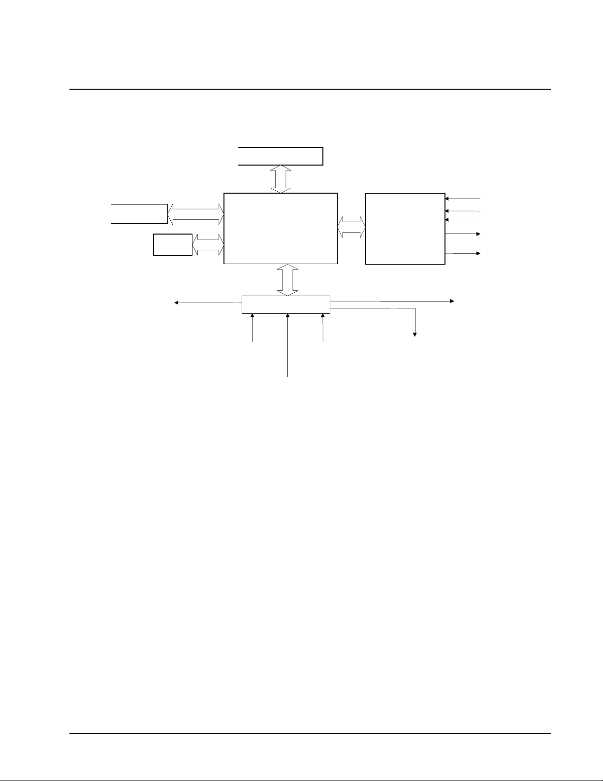
DMC-2x00 Functional Elements
The DMC-2x00 circuitry can be divided into the following functional groups as shown in Figure 1.1
and discussed below.
USB/ETHERNET
64 Configurable I/O
Figure 1.1 - DMC-2x00 Functional Elements
RS-232 /
RS-422
WATCHDOG TIMER
ISOLATED LIMITS AND
HOME INPUTS
68331
MICROCOMPUTER
WITH
4 Meg RAM
4 Meg FLASH EEPROM
I/O INTERFACE
8 UNCOMMITTED
ANALOG INPUTS
HIGH-SPEED LATCH FOR EACH AXIS
8 PROGRAMMABLE,
OPTOISOLATED
INPUTS
HIGH-SPEED
MOTOR/ENCODER
INTERFACE
FOR
A,B,C,D
8 PROGRAMMABLE
OUTPUTS
MAIN ENCODERS
AUXILIARY ENCODERS
+/- 10 VOLT OUTPUT FOR
SERVO MOTORS
PULSE/DIRECTION OUTPUT
FOR STEP MOTORS
HIGH SPEED ENCODER
COMPARE OUTPUT
Microcomputer Section
The main processing unit of the DMC-2x00 is a specialized 32-Bit Motorola 68331 Series
Microcomputer with 4 Meg RAM and 4 Meg Flash EEPROM. The RAM provides memory for
variables, array elements and application programs. The flash EEPROM provides non-volatile storage
of variables, programs, and arrays. It also contains the DMC-2x00 firmware.
Motor Interface
Galil’s GL-1800 custom, sub-micron gate array performs quadrature decoding of each encoder at up to
12 MHz. For standard servo operation, the controller generates a +/-10 volt analog signal (16 Bit
DAC). For sinusoidal commutation operation, the controller uses two DACs to generate two +/-10
volt analog signals. For stepper motor operation, the controller generates a step and direction signal.
Communication
The communication interface with the DMC-2x00 consists of high speed RS-232 and USB or high
speed RS-232 and Ethernet. The USB channel accepts based rates up to 12Mb/sec and the two RS-232
channels can generate up to 115K.
DMC-2X00 Chapter 1 Overview y 5
Page 16
General I/O
A
The DMC-2x00 provides interface circuitry for 8 bi-directional, optoisolated inputs, 8 TTL outputs and
8 analog inputs with 12-Bit ADC (16-Bit optional). The DMC-2x00 also has an additional 64 I/O and
unused auxiliary encoder inputs may also be used as additional inputs (2 inputs / each axis). The
general inputs can also be used as high speed latches for each axis. A high speed encoder compare
output is also provided.
2x80
The DMC-2x50 through DMC-2x80 controller provides an additional 8 optoisolated inputs and 8 TTL
outputs.
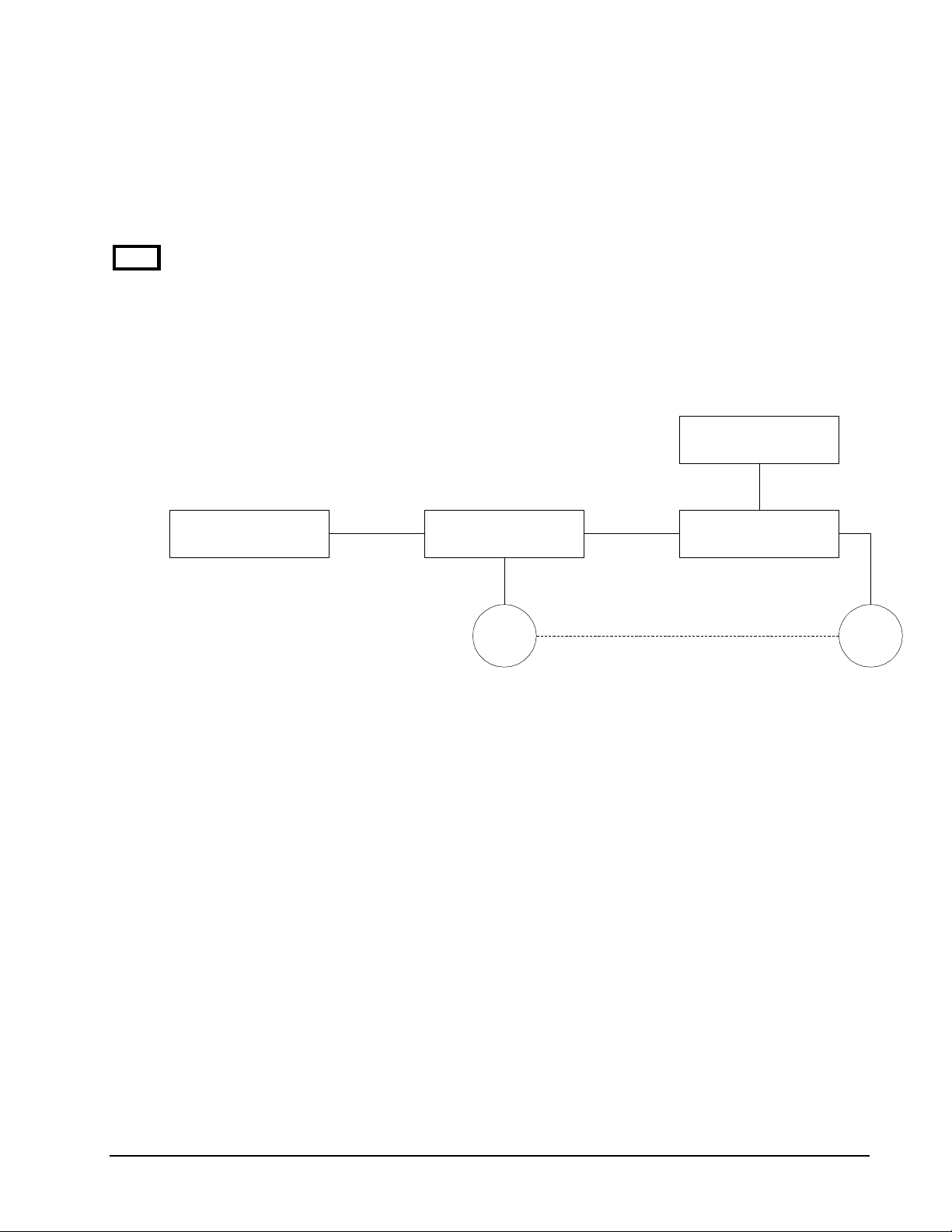
System Elements
As shown in Fig. 1.2, the DMC-2x00 is part of a motion control system which includes amplifiers,
motors and encoders. These elements are described below.
Power Supply
Computer DMC-2x00 Controller
Encoder Motor
Figure 1.2 - Elements of Servo systems
mplifier (Driver)
Motor
A motor converts current into torque which produces motion. Each axis of motion requires a motor
sized properly to move the load at the required speed and acceleration. (Galil's "Motion Component
Selector" software can help you with motor sizing). Contact Galil at 800-377-6329 if you would like
this product.
The motor may be a step or servo motor and can be brush-type or brushless, rotary or linear. For step
motors, the controller can be configured to control full-step, half-step, or microstep drives. An encoder
is not required when step motors are used.
Amplifier (Driver)
For each axis, the power amplifier converts a +/-10 volt signal from the controller into current to drive
the motor. For stepper motors, the amplifier converts step and direction signals into current. The
amplifier should be sized properly to meet the power requirements of the motor. For brushless motors,
an amplifier that provides electronic commutation is required or the controller must be configured to
provide sinusoidal commutation. The amplifiers may be either pulse-width-modulated (PWM) or
linear. They may also be configured for operation with or without a tachometer. For current
amplifiers, the amplifier gain should be set such that a 10 volt command generates the maximum
required current. For example, if the motor peak current is 10A, the amplifier gain should be 1 A/V.
For velocity mode amplifiers, 10 volts should run the motor at the maximum speed.
6 •Chapter 1 Overview DMC-2X00
Page 17

Encoder
An encoder translates motion into electrical pulses which are fed back into the controller. The DMC-
2x00 accepts feedback from either a rotary or linear encoder. Typical encoders provide two channels in
quadrature, known as CHA and CHB. This type of encoder is known as a quadrature encoder.
Quadrature encoders may be either single-ended (CHA and CHB) or differential (CHA,CHA- and
CHB,CHB-). The DMC-2x00 decodes either type into quadrature states or four times the number of
cycles. Encoders may also have a third channel (or index) for synchronization.
For stepper motors, the DMC-2x00 can also interface to encoders with pulse and direction signals.
There is no limit on encoder line density, however, the input frequency to the controller must not
exceed 3,000,000 full encoder cycles/second (12,000,000 quadrature counts/sec). For example, if the
encoder line density is 10000 cycles per inch, the maximum speed is 300 inches/second. If higher
encoder frequency is required, please consult the factory.
The standard voltage level is TTL (zero to five volts), however, voltage levels up to 12 volts are
acceptable. (If using differential signals, 12 volts can be input directly to the DMC-2x00. Single-
ended 12 volt signals require a bias voltage input to the complementary inputs).
The DMC-2x00 can accept analog feedback instead of an encoder for any axis.
To interface with other types of position sensors such as resolvers or absolute encoders, Galil can
customize the controller and command set. Please contact Galil and talk to one of our applications
engineers about your particular system requirements.
Watch Dog Timer
The DMC-2x00 provides an internal watch dog timer which checks for proper microprocessor
operation. The timer toggles the Amplifier Enable Output (AMPEN) which can be used to switch the
amplifiers off in the event of a serious DMC-2x00 failure. The AMPEN output is normally high.
During power-up and if the microprocessor ceases to function properly, the AMPEN output will go
low. The error light will also turn on at this stage. A reset is required to restore the DMC-2x00 to
normal operation. Consult the factory for a Return Materials Authorization (RMA) Number if your
DMC-2x00 is damaged.
DMC-2X00 Chapter 1 Overview y 7
Page 18

THIS PAGE LEFT BLANK INTENTIONALLY
8 •Chapter 1 Overview DMC-2X00
Page 19
Chapter 2 Getting Started
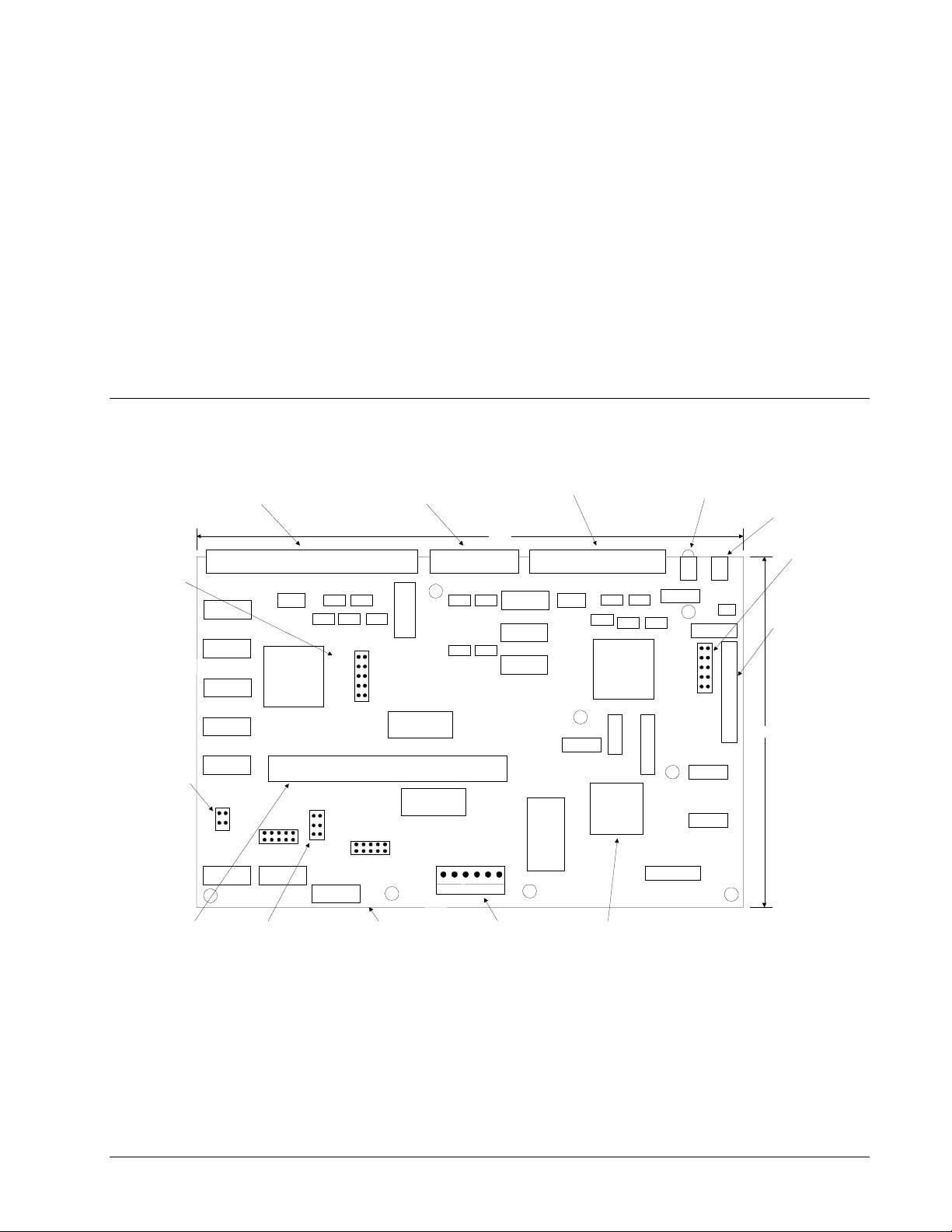
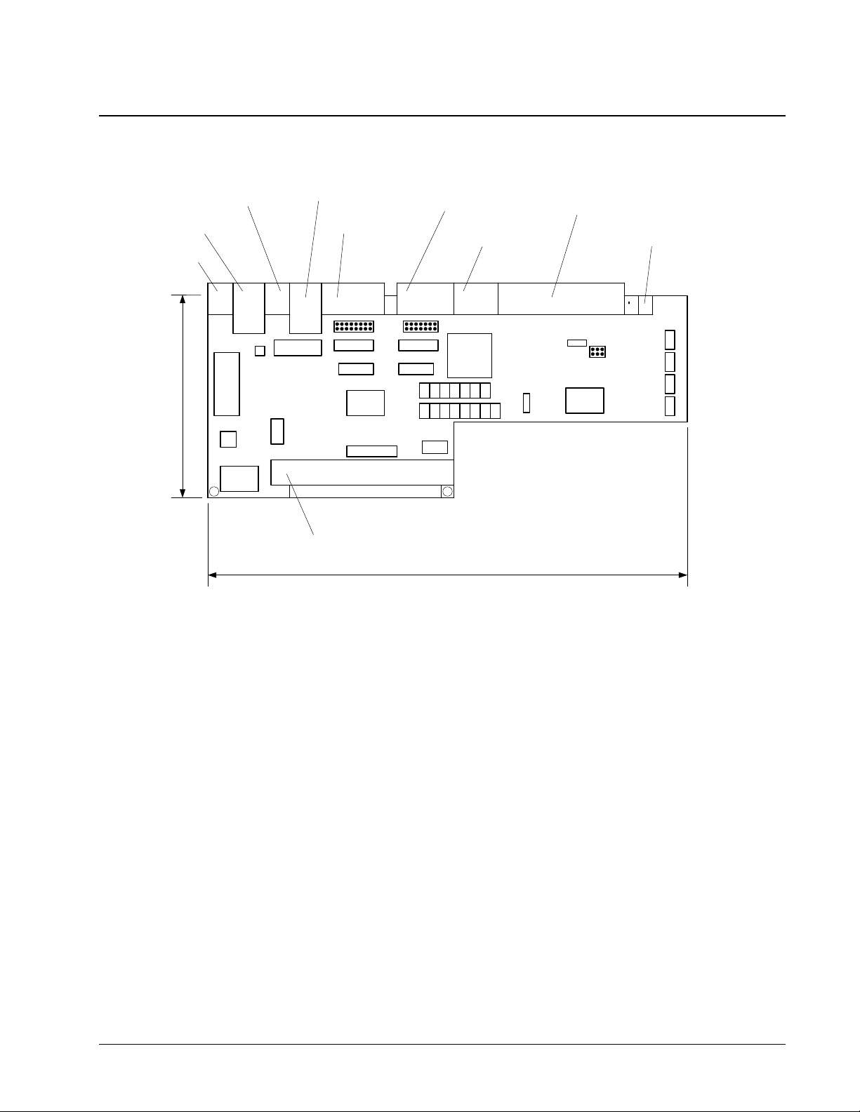
The DMC-2x00 Main Board
Stepper Motor
configuration
header
AXES E-H
100 pin high density connector
AMP part # 2-178238-9
J9
1
GL-1800
AUX Encoder inputs
36 pin high density connector
AXES E-H
SME
SMF
SMG
SMH
OPT2
JP7
AUX ENCODERS AXES A-D (X-W)J5 J1
SRAM
GALIL MOTION CONTROL
AXES A-D
100 pin high density connector
AMP part # 2-178238-9
9.50 "
DMC-2000
REV A
GL-1800
SMA(X)
SMB(Y)
SMC(Z)
SMD(W)
OPT1
Error,
Power
LED's
JP5
Reset
Switch
Stepper motor
configuration
header
Analog to Digital
Converter IC
7806 - 12 bit
7807 - 16 bit
SW1
ADS7806
5.80"
Jumper to
connect
onboard 5V
supply
Communications
Daughterboard
connector
JP3
LSCOM
INCOM
MADE IN USA
Jumper Master
Reset to clear
EEPROM
JP1
||| ||||| |||||
*AH-9999*
MASTER RESET
UPGRADE
*
Serial number label
SRAM
J2
-12V
GND
+5V
+5V
6 pin Molex
+12V
EEPROM
MicroprocessorPower connector
Motorola
68331
optoisolators to
Figure 2-1 - Outline of the main board of the DMC-2x00
DMC-2X00 Chapter 2 Getting Started y 9
Page 20
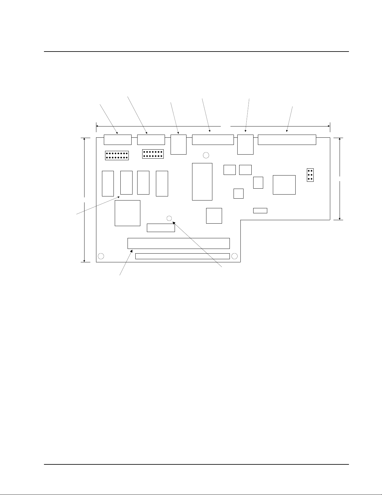
The DMC-2000 Daughter Board
AUX Serial port
DB-9 Female
AUX
JP4
MAIN Serial port
R485
R232
R232
TERM
DB-9 Male
J6
8 S
R422
R232
U7U2 U6
MC1489
MAIN J5
JP3
S 8
MC1488
R232
U1
R232
R232
USB type B
connector
J1
R485
TERM
USB IN
Configuration DIP
Switches
A1
A0
USB
USB type A
conne ctor (x2)
7.85 "
MRST
XON XO F
HSHK
9600
19.238A2
J2
J3
USB OUT
80 pin high
density connector
for extend ed I/O
EXTENDED I/O
2.53"
RS-232 buffer
IC's
3.94"
MADE IN USA
U9
CMB-2001
USB DAUGHTER CARD
GALIL MOTION CONTROL
REV C
D1
100 pin connector
(attaches to DMC-2000
Main board)
Figure 2-2 - Outline of the DMC-2000 Daughter Board
J4
1
A1
B1
C1
USB Communications
Status LED
10 • Chapter 2 Getting Started DMC-2X00
Page 21
The DMC-2200 Daughter Board
10 BASE-2
10 BASE-F
RECEIVER
3.94"
10 BASE-F
TRANSMITTER
100 BASE-T
AUX SERIAL PORT
DB-9 FEMALE
JP5
U15
MAIN SERIAL PORT
DB-9 MALE
JP4
U16
U6
JP4
JP5
U14
U4
485
232
232
232
TRM
185
232
232
232
TRM
1
CONFIGURATION
DIP SWITCHES
CMB-21002 REV A
GALIL MOTION CONTROL
1
8
S
8
S
422
80 PIN HIGH DENSITY
CONNECTOR FOR
EXTENDED I/O
COMMUNICATIONS
STATUS LED
D1 D2
J2
JP3
U1
100 PIN
CONNECTOR
(ATTACHES TO
DMC-2000 MAIN
BOARD)
J8
A1
B1
C1
J7
9.5"
Figure 2-3B - Outline of the DMC-2200 Daughter Board
DMC-2X00 Chapter 2 Getting Started y 11
Page 22
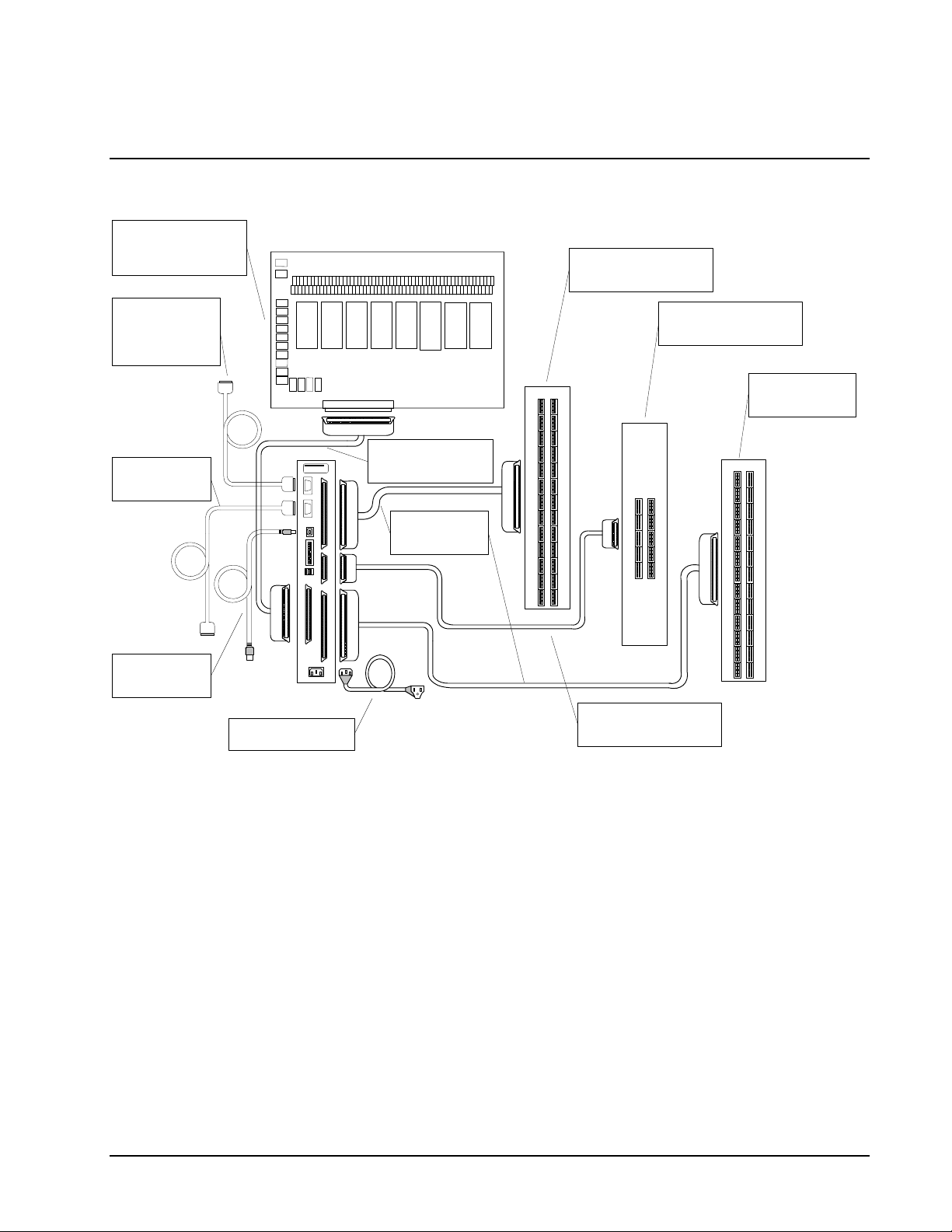
Elements You Need
Provides Opto-Isolation
and Interconnection for
Auxiliary Serial Port
(System Dependent
IOM-1964-80
Extended I/O
Connection
Cable)
0
132
IOM-1964-80
4
ICM-2900
Provides Connection to
Signals for Axes E-H
ICM-2908
7
6
5
Provides Connection to All
Auxiliary Encoder Sig n als
Cable 9-PinD
Main Serial Port to
Computer
CABLE-USB-2M
OR
CABLE-USB-3M
ICM-2900
GALIL
DMC-2000
Power Cable (Included
with the controller)
CABLE-80-1M (1Meter)
CABLE-80-4M (4Meter)
OR
CABLE-100-1M
OR
CABLE-100-4M
Figure 2-4 Recommended System Elements of DMC-2000
ICM-2908
CABLE-36-1M (1METER)
CABLE-36-4M (4METER)
OR
ICM-2900
Connection to
Signals for Axes A-D
ICM-2900
12 • Chapter 2 Getting Started DMC-2X00
Page 23
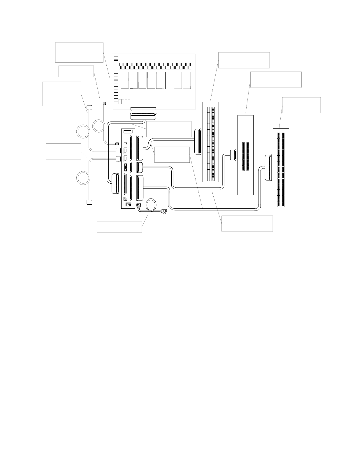
Provides Opto-Isolation
and Interconnection for
100/10 BASE-T
Cable
Auxiliary Serial Port
Connection
(System Dependent
Cable)
IOM-1964-80
Extended I/O
IOM-1964-80
0
132
GALIL
4
CABLE-80-1M (1Meter)
CABLE-80-4M (4Meter)
6
5
OR
7
ICM-2900
Provides Connection to
Signals for Axes E-H
ICM-2900
ICM-2908
Provides Connection to All
Auxiliary Encoder Signals
ICM-2908
ICM-2900
Connection to
Signals for Axes A-D
ICM-2900
Cable 9-PinD
Main Serial Port to
Computer
CABLE-100-1M
OR
CABLE-100-4M
DMC-2000
Power Cable (Included
with the controller)
CABLE-36-1M (1METER)
CABLE-36-4M (4METER)
Figure 2-5 Recommended System Elements of DMC-2100/DMC-2200
For a complete system, Galil recommends the following elements:
1a. DMC-2x10, 2x20, 2x30, or DMC-2x40 Motion Controller
or
1b. DMC-2x50, 2x60, 2x70 or DMC-2x80
OR
2a. (1) ICM-2900 and (1) CABLE-100 for controllers DMC-2x10 through DMC-2x40
or
2b. (2) ICM-2900's and (2) CABLE-100’s for controllers DMC-2x50 through DMC-2x80.
or
2c. An interconnect board provided by the user.
3. (1) IOM-1964 and (1) CABLE-80 for access to the extended I/O. Only required if extended
I/O will be used. The CABLE-80 can also be converted for use with OPTO-22 or Grayhill
I/O modules - consult Galil.
4. (1) ICM-2908 and (1) CABLE-36 for access to auxiliary encoders. Only required if auxiliary
encoders are needed.
DMC-2X00 Chapter 2 Getting Started y 13
Page 24

5. Motor Amplifiers.
6. Power Supply for Amplifiers.
7. Brush or Brushless Servo motors with Optical Encoders or stepper motors.
8. PC (Personal Computer - RS232 or USB for DMC-2000 or Ethernet for DMC-2100)
9a. WSDK-16 or WSDK-32 (recommend for first time users.)
or
9b. DMCWIN16, DMCWIN32 or DMCDOS communication software.
The WSDK software is highly recommended for first time users of the DMC-2x00. It provides stepby-step instructions for system connection, tuning and analysis.
Installing the DMC-2x00
Installation of a complete, operational DMC-2x00 system consists of 9 steps.
Step 1. Determine overall motor configuration.
Step 2. Install Jumpers on the DMC-2x00.
Step 3a. Configure the DIP switches on the DMC-2000.
Step 3b. Configure the DIP switches on the DMC-2100.
Step 3c. Configure the DIP switches on the DMC-2200
Step 4. Install the communications software.
Step 5. Connect AC power to controller.
Step 6. Establish communications with the Galil Communication Software.
Step 7. Determine the Axes to be used for sinusoidal commutation.
Step 8. Make connections to amplifier and encoder.
Step 9a. Connect standard servo motors.
Step 9b. Connect sinusoidal commutation motors
Step 9c. Connect step motors.
Step 10. Tune the servo system
Step 1. Determine Overall Motor Configuration
Before setting up the motion control system, the user must determine the desired motor configuration.
The DMC-2x00 can control any combination of standard servo motors, sinusoidally commutated
brushless motors, and stepper motors. Other types of actuators, such as hydraulics can also be
controlled, please consult Galil.
The following configuration information is necessary to determine the proper motor configuration:
Standard Servo Motor Operation:
The DMC-2x00 has been setup by the factory for standard servo motor operation providing an analog
command signal of +/- 10V. No hardware or software configuration is required for standard servo
motor operation.
14 • Chapter 2 Getting Started DMC-2X00
Page 25

Sinusoidal Commutation:
Sinusoidal commutation is configured through a single software command, BA. This configuration
causes the controller to reconfigure the number of available control axes.
Each sinusoidally commutated motor requires two DACs. In standard servo operation, the DMC-2x00
has one DAC per axis. In order to have the additional DAC for sinusoidal commutation, the controller
must be designated as having one additional axis for each sinusoidal commutation axis. For example,
to control two standard servo axes and one axis of sinusoidal commutation, the controller will require a
total of four DACs and the controller must be a DMC-2x40.
Sinusoidal commutation is configured with the command, BA. For example, BAA sets the A axis to
be sinusoidally commutated. The second DAC for the sinusoidal signal will be the highest available
DAC on the controller. For example: Using a DMC-2x40, the command BAA will configure the A
axis to be the main sinusoidal signal and the 'D' axis to be the second sinusoidal signal.
The BA command also reconfigures the controller to indicate that the controller has one less axis of
'standard' control for each axis of sinusoidal commutation. For example, if the command BAA is
given to a DMC-2x40 controller, the controller will be re-configured to a DMC-2x30 controller. By
definition, a DMC-2x30 controls 3 axes: A,B and C. The 'D' axis is no longer available since the
output DAC is being used for sinusoidal commutation.
Further instruction for sinusoidal commutation connections are discussed in Step 6.
Stepper Motor Operation
To configure the DMC-2x00 for stepper motor operation, the controller requires a jumper for each
stepper motor and the command, MT, must be given. The installation of the stepper motor jumper is
discussed in the following section entitled "Installing Jumpers on the DMC-2x00". Further instruction
for stepper motor connections are discussed in Step 9.
Step 2. Install Jumpers on the DMC-2x00
Master Reset and Upgrade Jumpers
JP1 on the main board contains two jumpers, MRST and UPGRD. The MRST jumper is the Master
Reset jumper. When MRST is connected, the controller will perform a master reset upon PC power up
or upon the reset input going low. The MRST can also be set with the DIP switches on the outside of
the controller. Whenever the controller has a master reset, all programs, arrays, variables, and motion
control parameters stored in EEPROM will be ERASED.
The UPGRD jumper enables the user to unconditionally update the controller’s firmware. This jumper
is not necessary for firmware updates when the controller is operating normally, but may be necessary
in cases of corrupted EEPROM. EEPROM corruption should never occur, however, it is possible if
there is a power fault during a firmware update. If EEPROM corruption occurs, your controller may
not operate properly. In this case, install the UPGRD Jumper and use the update firmware function on
the Galil Terminal to re-load the system firmware.
Opto-Isolation Jumpers
The inputs and limit switches are opto-isolated. If you are not using an isolated supply, the internal
+5V supply from the PC may be used to power the opto-isolators. This is done by installing jumpers
on JP3 on main board.
DMC-2X00 Chapter 2 Getting Started y 15
Page 26

Stepper Motor Jumpers
For each axis that will used for stepper motor operation, the corresponding stepper mode (SM) jumper
must be connected. The stepper mode jumpers, labeled JP5 and JP7 are located directly beside the
GL-1800 IC's on the main board (see the diagram of the DMC-2x00). The individual jumpers are
labeled SMA thru SMH and configure the controller for ‘Stepper Motors’ for the corresponding axes
A-H when installed. Note that the daughter board must be removed to access these jumpers. Contact
the Galil factory if stepper motor jumpers should be placed on your controller with each order for a
special part number.
(Optional) Motor Off Jumpers
The state of the motor upon power up may be selected with the placement of a hardware jumper on the
controller. With a jumper installed at the MO location, the controller will be powered up in the “motor
off” state. The SH command will need to be issued in order for the motor to be enabled. With no
jumper installed, the controller will immediately enable the motor upon power up. The MO command
will need to be issued to turn the motor off.
The MO jumper is always located on the same block of jumpers as the stepper motor jumpers (SM).
This feature is only available to newer revision controllers. Please consult Galil for adding this
functionality to older revision controllers.
Communications Jumpers for DMC-2000
The Main and Auxiliary Serial Communication Ports are normally connected for RS-232 connection.
The jumpers JP3 and JP4 on the DMC-2001 daughter-board allows the DMC-2000 to be configured
for RS-422. This can be specified as an option when the unit is purchased or the DMC-2000 may be
re-configured by the user, please consult Galil for instructions. Other serial communication protocols,
such as RS-485, can be implemented as a special - consult Galil.
Communications Jumpers for DMC-2100/DMC-2200
The main and Auxiliary Serial Commutations Ports are normally connected for RS-232 connection.
The jumpers JP4 and JP5 on the DMC-21001 daughter board allows the controller to be configured for
RS-422. This can be specified as an option when the unit is purchased or the controller may be reconfigured by the user, please consult Galil for instructions. Other serial communications protocols,
such as RS-485, can be implemented as a special - consult Galil.
Step 3a. Configure DIP switches on the DMC-2000
Located on the outside of the controller box is a set of 5 DIP switches. When the controller is powered
on or reset, the state of the dip switches are read.
Switch 1 - Master Reset
When this switch is on, the controller will perform a master reset upon PC power up. Whenever the
controller has a master reset, all programs and motion control parameters stored in EEPROM will be
ERASED. During normal operation, this switch should be off.
Switch 2 - XON / XOFF
When on, this switch will enable software handshaking (XON/XOFF) through the main serial port.
Switch 3 - Hardware Handshake Mode
When on, this switch will enable hardware handshaking through the main serial port.
16 • Chapter 2 Getting Started DMC-2X00
Page 27
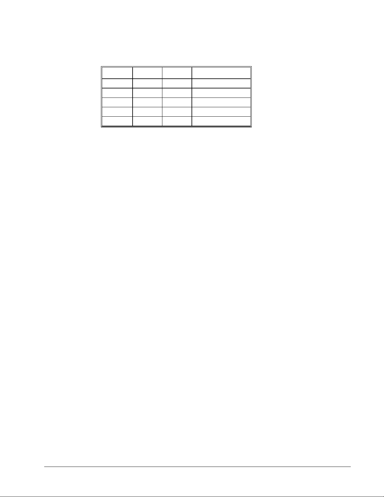
Switch 4, 5 and 6 - Main Serial Port Baud Rate
The following table describes the baud rate settings:
9600 19.2 3800 BAUD RATE
ON ON OFF 1200
ON OFF OFF 9600
OFF ON OFF 19200
OFF OFF ON 38400
OFF ON ON 115200
Switch 10 - USB
When on, the controller will use the USB port as a default port for messages. When off, the controller
will use the RS-232 port as default. When the firmware is updated, the controller will send the
response (a colon), to the default port setting. If this is not the same port that was used to download
the firmware, the Galil software will not return control to the user. In this case, the software will have
to be re-started.
Step 3b. Configure DIP switches on the DMC-2100
Switch 1 - Master Reset
When this switch is on, the controller will perform a master reset upon PC power up. Whenever the
controller has a master reset, all programs and motion control parameters stored in EEPROM will be
ERASED. During normal operation, this switch should be off.
Switch 2 - XON / XOFF
When on, this switch will enable software handshaking (XON/XOFF) through the main serial port.
Switch 3 - Hardware Handshake Mode
When on, this switch will enable hardware handshaking through the main serial port.
Step 3c. Configure DIP switches on the DMC-2200
Switch 1 - Master Reset
When this switch is on, the controller will perform a master reset upon PC power up. Whenever the
controller has a master reset, all programs and motion control parameters stored in EEPROM will be
ERASED. During normal operation, this switch should be off.
Switch 2 - XON / XOFF
When on, this switch will enable software handshaking (XON/XOFF) through the main serial port.
Switch 3 - Hardware Handshake Mode
When on, this switch will enable hardware handshaking through the main serial port.
DMC-2X00 Chapter 2 Getting Started y 17
Page 28
Switch 4,5 and 6 - Main Serial Port Baud Rate
The following table describes the baud rate settings:
9600 19.2 3800 BAUD RATE
ON ON OFF 1200
ON OFF OFF 9600
OFF ON OFF 19200
OFF OFF ON 38400
OFF ON ON 115200
Switch 7-Option
When OFF, the controller will use the auto-negotiate function to set the Ethernet connection speed.
When the DIP switch is ON, the controller defaults to 10BaseT.
Switch 8-Ethernet
When ON, the controller will use the Ethernet port as the default port for unsolicited messages. When
OFF, the controller will use the RS-232 port as the default. When the firmware is updated, the
controller will send the response (a colon) to the default port setting. If this is not the same port that
was used to download the firmware, the Galil software will not return control to the user. In this case,
the software will have to be re-started.
Step 4. Install the Communications Software
After applying power to the computer, you should install the Galil software that enables
communication between the controller and PC.
Using Windows 98SE, NT, ME, 2000 or XP:
The Galil Software CD-ROM will automatically begin the installation procedure when the CD-ROM is
installed. To install the basic communications software, run the Galil Software CD-ROM and choose
DMC Smart Term. This will install the Galil Smart Terminal, which can be used for communication.
Step 5. Connect AC Power to the Controller
Before applying power, connect the 100-pin cable between the DMC-2x00 and ICM-2900 interconnect
module. The DMC-2x00 requires a single AC supply voltage, single phase, 50 Hz or 60 Hz. from 90
volts to 260 volts.
WARNING: Dangerous voltages, current, temperatures and energy levels exist in this product and
the associated amplifiers and servo motor(s). Extreme caution should be exercised in the
application of this equipment. Only qualified individuals should attempt to install, set up and
operate this equipment. Never open the controller box when AC power is applied to it.
The green power light indicator should go on when power is applied.
18 • Chapter 2 Getting Started DMC-2X00
Page 29

Step 6. Establish Communications with Galil Software
Communicating through the Main Serial Communications Port
Connect the DMC-2x00 MAIN serial port to your computer via the Galil CABLE-9PIN-D (RS-232
Cable).
Using Galil Software for DOS (serial communication only)
To communicate with the DMC-2000, type TALK2DMC at the prompt. Once you have established
communication, the terminal display should show a colon, :. If you do not receive a colon, press the
carriage return. If a colon prompt is not returned, there is most likely an incorrect setting of the serial
communications port. The user must ensure that the correct communication port and baud rate are
specified when attempting to communicate with the controller. Please note that the serial port on the
controller must be set for handshake mode for proper communication with Galil software. The user
must also insure that the proper serial cable is being used, see appendix for pin-out of serial cable.
Using Galil Software for Windows
In order for the windows software to communicate with a Galil controller, the controller must be
registered in the Windows Registry. To register a controller, you must specify the model of the
controller, the communication parameters, and other information. The registry is accessed through the
Galil software under the “File” menu in WSDK or under the “Tools” menu in the Galil Smart
Terminal.
The registry window is equipped with buttons to Add a New Controller, change the Properties of an
existing controller, Delete a controller, or Find an Ethernet Controller.
Use the “New Controller” button to add a new entry to the Registry. You will need to supply the
Galil Controller model (eg: DMC-2000). Pressing the down arrow to the right of this field will reveal
a menu of valid controller types. You then need to choose serial or Ethernet connection. Remember, a
DMC-2000 connected via USB is plug and play and should be automatically added to the registry
upon connection. The registry information will show a default Comm Port of 1 and a default Comm
Speed of 19200 appears. This information can be changed as necessary to reflect the computers
Comm Port and the baud rate set by the dip switches on the front of the controller (default is 19200
with HSHK on). The registry entry also displays timeout and delay information. These are advanced
parameters which should only be modified by advanced users (see software documentation for more
information).
Once you have set the appropriate Registry information for your controller, Select OK and close the
registry window. You will now be able to communicate with the controller.
If you are not properly communicating with the controller, the program will pause for 3-15 seconds
and an error message will be displayed. In this case, there is most likely an incorrect setting of the
serial communications port or the serial cable is not connected properly. The user must ensure that the
correct communication port and baud rate are specified when attempting to communicate with the
controller. Please note that the serial port on the controller must be set for handshake mode for proper
communication with Galil software. The user must also insure that a “straight-through” serial cable is
being used (NOT a Null Modem cable), see appendix for pin-out of serial cable.
Once you establish communications, open up the Terminal and hit the “Enter” key. You should
receive a colon prompt. Communicating with the controller is described in later sections.
DMC-2X00 Chapter 2 Getting Started y 19
Page 30

Using Non-Galil Communication Software
The DMC-2x00 main serial port is configured as DATASET. Your computer or terminal must be
configured as a DATATERM for full duplex, no parity, 8 data bits, one start bit and one stop bit.
Check to insure that the baud rate switches have been set to the desired baud rate as described above.
Your computer needs to be configured as a "dumb" terminal which sends ASCII characters as they are
typed to the DMC-2x00.
Communicating through the Universal Serial Bus (USB)
NOTE: Galil Software only supports the use of the USB port under Windows 98SE, ME, 2000 and
XP.
Connect the USB cable from the computer to the USB IN port on the controller. Since the controller
has been powered on in the previous step, the computer will recognize the first connection to a Galil
USB controller. The computer will identify the USB controller and add it to the Windows Registry as
a plug and play device.
Communicating through the Ethernet
Using Galil Software for Windows
The controller must be registered in the Windows registry for the host computer to communicate with
it. The registry may be accessed via Galil software, such as WSDK or SmartTERM.
From WSDK, the registry is accessed under the FILE menu. From Smart TERM it is accessed under
the TOOLS menu. Use the NEW CONTROLLER button to add a new entry in the registry. Choose
DMC-2100 or DMC-2200 as the controller type. Enter the IP address obtained from your system
administrator. Select the button corresponding to the UDP or TCP protocol in which you wish to
communicate with the controller. If the IP address has not been already assigned to the controller,
click on ASSIGN IP ADDRESS.
ASSIGN IP ADDRESS will check the controllers that are linked to the network to see which ones do
not have an IP address. The program will then ask you whether you would like to assign the IP
20 • Chapter 2 Getting Started DMC-2X00
Page 31

address you entered to the controller with the specified serial number. Click on YES to assign it, NO
to move to next controller, or CANCEL to not save the changes. If there are no controllers on the
network that do not have an IP address assigned, the program will state this.
When done registering, click on OK. If you do not wish to save the changes, click on CANCEL.
Once the controller has been register, select the correct controller from the list and click on OK. If the
software successfully established communications with the controller, the registry entry will be
displayed at the top of the screen.
NOTE: The controller must be registered via an Ethernet connection.
Sending Test Commands to the Terminal:
After you connect your terminal, press <return> or the <enter> key on your keyboard. In response to
carriage return <return>, the controller responds with a colon, :
Now type
TPA <return>
This command directs the controller to return the current position of the A axis. The controller should
respond with a number such as
0000000
Step 7. Determine the Axes to be Used for Sinusoidal Commutation
* This step is only required when the controller will be used to control a brushless motor(s) with
sinusoidal commutation.
The command, BA is used to select the axes of sinusoidal commutation. For example, BAAC sets A
and C as axes with sinusoidal commutation.
Notes on Configuring Sinusoidal Commutation:
The command, BA, reconfigures the controller such that it has one less axis of 'standard' control for
each axis of sinusoidal commutation. For example, if the command BAA is given to a DMC-2x40
controller, the controller will be re-configured to be a DMC-2x30 controller. In this case the highest
axis is no longer available except to be used for the 2
the highest axis on a controller can never be configured for sinusoidal commutation.
The DAC associated with the selected axis represents the first phase. The second phase uses the
highest available DAC. When more than one axis is configured for sinusoidal commutation, the
controller will assign the second phases to the DACs which have been made available through the axes
reconfiguration. The highest sinusoidal commutation axis will be assigned to the highest available
DAC and the lowest sinusoidal commutation axis will be assigned to the lowest available DAC. Note
that the lowest axis is the A axis and the highest axis is the highest available axis for which the
controller has been configured.
nd
phase of the sinusoidal commutation. Note that
Example: Sinusoidal Commutation Configuration using a DMC-2x70
BAAC
This command causes the controller to be reconfigured as a DMC-2x50 controller. The A and C axes
are configured for sinusoidal commutation. The first phase of the A axis will be the motor command
A signal. The second phase of the A axis will be F signal. The first phase of the C axis will be the
motor command C signal. The second phase of the C axis will be the motor command G signal.
DMC-2X00 Chapter 2 Getting Started y 21
Page 32

Step 8. Make Connections to Amplifier and Encoder.
Once you have established communications between the software and the DMC-2x00, you are ready to
connect the rest of the motion control system. The motion control system typically consists of an
ICM-2900 Interface Module, an amplifier for each axis of motion, and a motor to transform the current
from the amplifier into torque for motion.
If you are using an ICM-2900, connect it to the DMC-2x00 via the 100-pin high density cable. The
ICM-2900 provides screw terminals for access to the connections described in the following
discussion.
2x80
WARNING: When the amplifier ground is not isolated from the power line or when it has a different
potential than that of the computer ground, serious damage may result to the computer controller
and amplifier.
Motion Controllers with more than 4 axes require a second ICM-2900 and 100-pin cable.
System connection procedures will depend on system components and motor types. Any combination
of motor types can be used with the DMC-2x00. If sinusoidal commutation is to be used, special
attention must be paid to the reconfiguration of axes.
Here are the first steps for connecting a motion control system:
Step A. Connect the motor to the amplifier with no connection to the controller. Consult the
amplifier documentation for instructions regarding proper connections. Connect and turn-on
the amplifier power supply. If the amplifiers are operating properly, the motor should stand
still even when the amplifiers are powered up.
Step B. Connect the amplifier enable signal.
Before making any connections from the amplifier to the controller, you need to verify that
the ground level of the amplifier is either floating or at the same potential as earth.
If you are not sure about the potential of the ground levels, connect the two ground signals
(amplifier ground and earth) by a 10 kΩ resistor and measure the voltage across the resistor.
Only if the voltage is zero, connect the two ground signals directly.
The amplifier enable signal is used by the controller to disable the motor. This signal is
labeled AMPENA for the A axis on the ICM-2900 and should be connected to the enable
signal on the amplifier. Note that many amplifiers designate this signal as the INHIBIT
signal. Use the command, MO, to disable the motor amplifiers - check to insure that the
motor amplifiers have been disabled (often this is indicated by an LED on the amplifier).
This signal changes under the following conditions: the watchdog timer activates, the motor-
off command, MO, is given, or the OE1 command (Enable Off-On-Error) is given and the
position error exceeds the error limit. AMPEN can be used to disable the amplifier for these
conditions.
The standard configuration of the AMPEN signal is TTL active high. In other words, the
AMPEN signal will be high when the controller expects the amplifier to be enabled. The
polarity and the amplitude can be changed if you are using the ICM-2900 interface board. To
change the polarity from active high (5 volts = enable, zero volts = disable) to active low
(zero volts = enable, 5 volts = disable), replace the 7407 IC with a 7406. Note that many
amplifiers designate the enable input as ‘inhibit’.
To change the voltage level of the AMPEN signal, note the state of the resistor pack on the
ICM-2900. When Pin 1 is on the 5V mark, the output voltage is 0-5V. To change to 12 volts,
pull the resistor pack and rotate it so that Pin 1 is on the 12 volt side. If you remove the
resistor pack, the output signal is an open collector, allowing the user to connect an external
supply with voltages up to 24V.
Step C. Connect the encoders
22 • Chapter 2 Getting Started DMC-2X00
Page 33

For stepper motor operation, an encoder is optional.
For servo motor operation, if you have a preferred definition of the forward and reverse
directions, make sure that the encoder wiring is consistent with that definition.
The DMC-2x00 accepts single-ended or differential encoder feedback with or without an
index pulse. If you are not using the ICM-2900 you will need to consult the appendix for the
encoder pinouts for connection to the motion controller. The ICM-2900 accepts encoder
feedback via individual signal leads. Simply match the leads from the encoder you are using
to the encoder feedback inputs on the interconnect board. The signal leads are labeled CHA
(channel A), CHB (channel B), and INDEX. For differential encoders, the complement
signals are labeled CHA-, CHB-, and INDEX-.
NOTE: When using pulse and direction encoders, the pulse signal is connected to CHA and the
direction signal is connected to CHB. The controller must be configured for pulse and direction
with the command CE. See the command summary for further information on the command CE.
Step D. Verify proper encoder operation.
Start with the A encoder first. Once it is connected, turn the motor shaft and interrogate the
position with the instruction TPA <return>. The controller response will vary as the motor is
turned.
At this point, if TPA does not vary with encoder rotation, there are three possibilities:
1. The encoder connections are incorrect - check the wiring as necessary.
2. The encoder has failed - using an oscilloscope, observe the encoder signals. Verify
that both channels A and B have a peak magnitude between 5 and 12 volts. Note
that if only one encoder channel fails, the position reporting varies by one count
only. If the encoder failed, replace the encoder. If you cannot observe the encoder
signals, try a different encoder.
3. There is a hardware failure in the controller - connect the same encoder to a different
axis. If the problem disappears, you probably have a hardware failure. Consult the
factory for help.
Step E. Connect Hall Sensors if available.
Hall sensors are only used with sinusoidal commutation and are not necessary for proper
operation. The use of Hall sensors allows the controller to automatically estimate the
commutation phase upon reset and also provides the controller the ability to set a more precise
commutation phase. Without Hall sensors, the commutation phase must be determined
manually.
The Hall effect sensors are connected to the digital inputs of the controller. These inputs can
be used with the general use inputs (bits 1-8), the auxiliary encoder inputs (bits 81-96), or the
extended I/O inputs of the DMC-2x00 controller (bits 17-80).
NOTE: The general use inputs are optoisolated and require a voltage connection at the INCOM
point - for more information regarding the digital inputs, see Chapter 3, Connecting Hardware.
Each set of sensors must use inputs that are in consecutive order. The input lines are specified
with the command, BI. For example, if the Hall sensors of the C axis are connected to inputs
6, 7 and 8, use the instruction:
BI ,, 6 or
BIC = 6
DMC-2X00 Chapter 2 Getting Started y 23
Page 34

Step 9a. Connect Standard Servo Motors
The following discussion applies to connecting the DMC-2x00 controller to standard servo motor
amplifiers:
The motor and the amplifier may be configured in the torque or the velocity mode. In the torque
mode, the amplifier gain should be such that a 10 volt signal generates the maximum required current.
In the velocity mode, a command signal of 10 volts should run the motor at the maximum required
speed.
Step by step directions on servo system setup are also included on the WSDK (Windows Servo Design
Kit) software offered by Galil. See section on WSDK for more details.
Step A. Check the Polarity of the Feedback Loop
It is assumed that the motor and amplifier are connected together and that the encoder is
operating correctly (Step B). Before connecting the motor amplifiers to the controller, read
the following discussion on setting Error Limits and Torque Limits. Note that this discussion
only uses the A axis as an examples.
Step B. Set the Error Limit as a Safety Precaution
Usually, there is uncertainty about the correct polarity of the feedback. The wrong polarity
causes the motor to run away from the starting position. Using a terminal program, such as
DMCTERM, the following parameters can be given to avoid system damage:
Input the commands:
ER 2000 <CR> Sets error limit on the A axis to be 2000 encoder counts
OE 1 <CR> Disables A axis amplifier when excess position error exists
If the motor runs away and creates a position error of 2000 counts, the motor amplifier will be
disabled.
NOTE: This function requires the AMPEN signal to be connected from the controller to the
amplifier.
Step C. Set Torque Limit as a Safety Precaution
To limit the maximum voltage signal to your amplifier, the DMC-2x00 controller has a torque
limit command, TL. This command sets the maximum voltage output of the controller and
can be used to avoid excessive torque or speed when initially setting up a servo system.
When operating an amplifier in torque mode, the voltage output of the controller will be
directly related to the torque output of the motor. The user is responsible for determining this
relationship using the documentation of the motor and amplifier. The torque limit can be set
to a value that will limit the motors output torque.
When operating an amplifier in velocity or voltage mode, the voltage output of the controller
will be directly related to the velocity of the motor. The user is responsible for determining
this relationship using the documentation of the motor and amplifier. The torque limit can be
set to a value that will limit the speed of the motor.
For example, the following command will limit the output of the controller to 1 volt on the X
axis:
TL 1 <CR>
NOTE: Once the correct polarity of the feedback loop has been determined, the torque limit
should, in general, be increased to the default value of 9.99. The servo will not operate properly if
the torque limit is below the normal operating range. See description of TL in the command
reference.
24 • Chapter 2 Getting Started DMC-2X00
Page 35

Step D. Connect the Motor
Once the parameters have been set, connect the analog motor command signal (ACMD) to the
amplifier input.
To test the polarity of the feedback, command a move with the instruction:
PR 1000 <CR> Position relative 1000 counts
BGA <CR> Begin motion on A axis
When the polarity of the feedback is wrong, the motor will attempt to run away. The
controller should disable the motor when the position error exceeds 2000 counts. If the motor
runs away, the polarity of the loop must be inverted.
Inverting the Loop Polarity
When the polarity of the feedback is incorrect, the user must invert the loop polarity and this may be
accomplished by several methods. If you are driving a brush-type DC motor, the simplest way is to
invert the two motor wires (typically red and black). For example, switch the M1 and M2 connections
going from your amplifier to the motor. When driving a brushless motor, the polarity reversal may be
done with the encoder. If you are using a single-ended encoder, interchange the signal CHA and CHB.
If, on the other hand, you are using a differential encoder, interchange only CHA+ and CHA-. The
loop polarity and encoder polarity can also be affected through software with the MT, and CE
commands. For more details on the MT command or the CE command, see the Command Reference
section.
Sometimes the feedback polarity is correct (the motor does not attempt to run away) but the direction
of motion is reversed with respect to the commanded motion. If this is the case, reverse the motor
leads AND the encoder signals.
If the motor moves in the required direction but stops short of the target, it is most likely due to
insufficient torque output from the motor command signal ACMD. This can be alleviated by reducing
system friction on the motors. The instruction:
TTA <return> Tell torque on A
reports the level of the output signal. It will show a non-zero value that is below the friction level.
Once you have established that you have closed the loop with the correct polarity, you can move on to
the compensation phase (servo system tuning) to adjust the PID filter parameters, KP, KD and KI. It is
necessary to accurately tune your servo system to ensure fidelity of position and minimize motion
oscillation as described in the next section.
DMC-2X00 Chapter 2 Getting Started y 25
Page 36

ICM-2900
MOCMDZ
SIGNZ
PWMZ
GND
MOCMDX
SIGNX
PWMX
GND
OUT PWR
ERROR
CMP
OUT GND
OUT5
OUT6
OUT7
OUT8
+5V
HOMEZ
RLSZ
FLSZ
HOMEX
RLSX
FLSX
GND
+12V
-12V
ANA GND
ANALOG5
ANALOG6
ANALOG7
ANALOG8
+INX
-INX
GND
+INY
-INY
GND
+INZ
-INZ
GND
+5V
+INW
-INW
GND
+5V
+5V
+5V
+5V
MOCMDW
SIGNW
PWMW
GND
MOCMDY
SIGNY
PWMY
GND
AMPENW
AMPENZ
AMPENY
AMPENX
OUT1
OUT2
OUT3
OUT4
LSCOM
HOMEW
RLSW
FLSW
HOMEY
RLSY
FLSY
GND
IN5
IN6
IN7
IN8
XLATCH
YLATCH
ZLATCH
WLATCH
INCOM
ABORT
RESET
GND
ANALOG1
ANALOG2
ANALOG3
ANALOG4
+MAX
-MAX
+MBX
-MBX
+MAY
-MAY
+MBY
-MBY
+MAZ
-MAZ
+MBZ
-MBZ
+MAW
-MAW
+MBW
-MBW
Signal Gnd 2
+Ref In 4
Inhibit* 11
Motor + 1
Motor - 2
Power Gnd 4
High Volt 5
-
Encoder
MSA 12-80
+
CPS Power
Supply
+
-
DC Servo Motor
Figure 2-6 System Connections with a separate amplifier (MSA 12-80). This diagram shows the connections for a
standard DC Servo Motor and encoder
26 • Chapter 2 Getting Started DMC-2X00
Page 37

Step 9b. Connect Sinusoidal Commutation Motors
When using sinusoidal commutation, the parameters for the commutation must be determined and
saved in the controller’s non-volatile memory. The setup for sinusoidal commutation is
different when using Hall Sensors. Each step which is affected by Hall Sensor Operation is
divided into two parts, part 1 and part 2. After connecting sinusoidal commutation motors,
the servos must be tuned as described in Step 10.
Step A. Disable the motor amplifier
Use the command, MO, to disable the motor amplifiers. For example, MOA will turn the A
axis motor off.
Step B. Connect the motor amplifier to the controller.
The sinusoidal commutation amplifier requires 2 signals, usually denoted as Phase A & Phase
B. These inputs should be connected to the two sinusoidal signals generated by the controller.
The first signal is the axis specified with the command, BA (Step 6). The second signal is
associated with the highest analog command signal available on the controller - note that this
axis was made unavailable for standard servo operation by the command BA.
When more than one axis is configured for sinusoidal commutation, the controller will assign
the second phase to the command output which has been made available through the axes
reconfiguration. The 2
command output and the 2
lowest command output.
It is not necessary to be concerned with cross-wiring the 1
incorrect, the setup procedure will alert the user (Step D).
nd
phase of the highest sinusoidal commutation axis will be the highest
nd
phase of the lowest sinusoidal commutation axis will be the
st
and 2nd signals. If this wiring is
Example: Sinusoidal Commutation Configuration using a DMC2x70
BAAC
This command causes the controller to be reconfigured as a DMC-2x50 controller. The A and
C axes are configured for sinusoidal commutation. The first phase of the A axis will be the
motor command A signal. The second phase of the A axis will be the motor command F
signal. The first phase of the C axis will be the motor command C signal. The second phase
of the C axis will be the motor command G signal.
Step C. Specify the Size of the Magnetic Cycle.
Use the command, BM, to specify the size of the brushless motors magnetic cycle in encoder
counts. For example, if the X axis is a linear motor where the magnetic cycle length is 62
mm, and the encoder resolution is 1 micron, the cycle equals 62,000 counts. This can be
commanded with the command:
BM 62000
On the other hand, if the C axis is a rotary motor with 4000 counts per revolution and 3
magnetic cycles per revolution (three pole pairs) the command is:
BM,, 1333.333
Step D - part 1 (Systems with or without Hall Sensors). Test the Polarity of the DACs
Use the brushless motor setup command, BS, to test the polarity of the output DACs. This
command applies a certain voltage, V, to each phase for some time T, and checks to see if the
motion is in the correct direction.
DMC-2X00 Chapter 2 Getting Started y 27
Page 38

The user must specify the value for V and T. For example, the command:
BSA = 2,700
will test the A axis with a voltage of 2 volts, applying it for 700 millisecond for each phase.
In response, this test indicates whether the DAC wiring is correct and will indicate an
approximate value of BM. If the wiring is correct, the approximate value for BM will agree
with the value used in the previous step.
NOTE: In order to properly conduct the brushless setup, the motor must be allowed to move a
minimum of one magnetic cycle in both directions.
NOTE: When using Galil Windows software, the timeout must be set to a minimum of 10
seconds (time-out = 10000) when executing the BS command. This allows the software to
retrieve all messages returned from the controller.
Step D - part 2 (Systems with Hall Sensors Only). Test the Hall Sensor Configuration.
Since the Hall sensors are connected randomly, it is very likely that they are wired in the
incorrect order. The brushless setup command indicates the correct wiring of the Hall
sensors. The Hall sensor wires should be re-configured to reflect the results of this test.
The setup command also reports the position offset of the Hall transition point and the zero
phase of the motor commutation. The zero transition of the Hall sensors typically occur at
0°, 30° or 90° of the phase commutation. It is necessary to inform the controller about the
offset of the Hall sensor and this is done with the instruction, BB.
Step E. Save Brushless Motor Configuration
It is very important to save the brushless motor configuration in non-volatile memory. After
the motor wiring and setup parameters have been properly configured, the burn command,
BN, should be given.
NOTE: Without Hall sensors, the controller will not be able to estimate the commutation phase
of the brushless motor. In this case, the controller could become unstable until the commutation
phase has been set using the BZ command (see next step). It is highly recommended that the
motor off command be given before executing the BN command. In this case, the motor will be
disabled upon power up or reset and the commutation phase can be set before enabling the motor.
Step F - part 1 (Systems with or without Hall Sensors). Set Zero Commutation Phase
When an axis has been defined as sinusoidally commutated, the controller must have an
estimate for commutation phase. When Hall sensors are used, the controller automatically
estimates this value upon reset of the controller. If no Hall sensors are used, the controller
will not be able to make this estimate and the commutation phase must be set before enabling
the motor.
To initialize the commutation without Hall effect sensor use the command, BZ. This function
drives the motor to a position where the commutation phase is zero, and sets the phase to zero.
The BZ command is followed by real numbers in the fields corresponding to the driven axes.
The number represents the voltage to be applied to the amplifier during the initialization.
When the voltage is specified by a positive number, the initialization process ends up in the
motor off (MO) state. A negative number causes the process to end in the Servo Here (SH)
state.
28 • Chapter 2 Getting Started DMC-2X00
Page 39

WARNING: This command must move the motor to find the zero commutation phase. This
movement is instantaneous and will cause the system to jerk. Larger applied voltages will cause
more severe motor jerk. The applied voltage will typically be sufficient for proper operation of the
BZ command. For systems with significant friction, this voltage may need to be increased and for
systems with very small motors, this value should be decreased. For example:
BZ –2, 0,1
will drive both A and C axes to zero, will apply 2V and 1V respectively to A and C and will end up
with A in SH and C in MO.
Step F - part 2 (Systems with Hall Sensors Only). Set Zero Commutation Phase
With Hall sensors, the estimated value of the commutation phase is good to within 30°. This
estimate can be used to drive the motor but a more accurate estimate is needed for efficient
motor operation. There are 3 possible methods for commutation phase initialization:
Method 1. Use the BZ command as described above.
Method 2. Drive the motor close to commutation phase of zero and then use BZ command.
This method decreases the amount of system jerk by moving the motor close to zero
commutation phase before executing the BZ command. The controller makes an estimate for
the number of encoder counts between the current position and the position of zero
commutation phase. This value is stored in the operand _BZn. Using this operand the
controller can be commanded to move the motor. The BZ command is then issued as
described above. For example, to initialize the A axis motor upon power or reset, the
following commands may be given:
SHA ;Enable A axis motor
PRA=-1*(_BZA) ;Move A motor close to zero commutation phase
BGA ;Begin motion on A axis
AMA ;Wait for motion to complete on A axis
BZA=-1 ;Drive motor to commutation phase zero and leave
;motor on
Method 3. Use the command, BC. This command uses the Hall transitions to determine the
commutation phase. Ideally, the Hall sensor transitions will be separated by exactly 60° and
any deviation from 60° will affect the accuracy of this method. If the Hall sensors are
accurate, this method is recommended. The BC command monitors the Hall sensors during a
move and monitors the Hall sensors for a transition point. When that occurs, the controller
computes the commutation phase and sets it. For example, to initialize the A axis motor upon
power or reset, the following commands may be given:
SHA ;Enable A axis motor
BCA ;Enable the brushless calibration command
PRA=50000 ;Command a relative position movement on A axis
BGA ;Begin motion on A axis. When the Hall sensors
; detect a phase transition, the commutation phase is
;re-set.
DMC-2X00 Chapter 2 Getting Started y 29
Page 40

Step 9c. Connect Step Motors
In Stepper Motor operation, the pulse output signal has a 50% duty cycle. Step motors operate open
loop and do not require encoder feedback. When a stepper is used, the auxiliary encoder for the
corresponding axis is unavailable for an external connection. If an encoder is used for position
feedback, connect the encoder to the main encoder input corresponding to that axis. The commanded
position of the stepper can be interrogated with RP or TD. The encoder position can be interrogated
with TP.
The frequency of the step motor pulses can be smoothed with the filter parameter, KS. The KS
parameter has a range between 0.5 and 8, where 8 implies the largest amount of smoothing. See
Command Reference regarding KS.
The DMC-2x00 profiler commands the step motor amplifier. All DMC-2x00 motion commands apply
such as PR, PA, VP, CR and JG. The acceleration, deceleration, slew speed and smoothing are also
used. Since step motors run open-loop, the PID filter does not function and the position error is not
generated.
To connect step motors with the DMC-2x00 you must follow this procedure:
Step A. Install SM jumpers
Each axis of the DMC-2x00 that will operate a stepper motor must have the corresponding
stepper motor jumper installed. For a discussion of SM jumpers, see section
Jumpers on the DMC-2x00.
Step B. Connect step and direction signals from controller to motor amplifier
From the controller to respective signals on your step motor amplifier. (These signals are
labeled PULSX and DIRX for the A-axis on the ICM-2900). Consult the documentation for
your step motor amplifier.
Step 2. Install
Step C. Configure DMC-2x00 for motor type using MT command. You can configure the DMC-
2x00 for active high or active low pulses. Use the command MT 2 for active low step motor
pulses and MT -2 for active high step motor pulses. See description of the MT command in
the Command Reference.
Step 10. Tune the Servo System
Adjusting the tuning parameters is required when using servo motors (standard or sinusoidal
commutation). The system compensation provides fast and accurate response and the following
presentation suggests a simple and easy way for compensation. More advanced design methods are
available with software design tools from Galil, such as the Servo Design Kit (SDK software)
The filter has three parameters: the damping, KD; the proportional gain, KP; and the integrator, KI.
The parameters should be selected in this order.
To start, set the integrator to zero with the instruction
KI 0 <return> Integrator gain
and set the proportional gain to a low value, such as
KP 1 <return> Proportional gain
KD 100 <return> Derivative gain
30 • Chapter 2 Getting Started DMC-2X00
Page 41

For more damping, you can increase KD (maximum is 4095). Increase gradually and stop after the
motor vibrates. A vibration is noticed by audible sound or by interrogation. If you send the command
TE A <return> Tell error
a few times, and get varying responses, especially with reversing polarity, it indicates system vibration.
When this happens, simply reduce KD.
Next you need to increase the value of KP gradually (maximum allowed is 1023). You can monitor the
improvement in the response with the Tell Error instruction
KP 10 <return> Proportion gain
TE A <return> Tell error
As the proportional gain is increased, the error decreases.
Again, the system may vibrate if the gain is too high. In this case, reduce KP. Typically, KP should
not be greater than KD/4 (only when the amplifier is configured in the current mode).
Finally, to select KI, start with zero value and increase it gradually. The integrator eliminates the
position error, resulting in improved accuracy. Therefore, the response to the instruction
TE A <return>
becomes zero. As KI is increased, its effect is amplified and it may lead to vibrations. If this occurs,
simply reduce KI. Repeat tuning for the B, C and D axes.
For a more detailed description of the operation of the PID filter and/or servo system theory, see
Chapter 10 - Theory of Operation.
Design Examples
Here are a few examples for tuning and using your controller. These examples have remarks next to
each command - these remarks must not be included in the actual program.
System Set-up
This example assigns the system filter parameters, error limits and enables the automatic error shut-off.
Instruction Interpretation
KP10,10,10,10 Set gains for a,b,c,d (or A,B,C,D axes)
KP*=10 Alternate method for setting gain on all axes
KPA=10 Method for setting only A axis gain
KP, 20 Set B axis gain only
Instruction Interpretation
OE 1,1,1,1,1,1,1,1 Enable automatic Off on Error function for all axes
ER*=1000 Set error limit for all axes to 1000 counts
KP10,10,10,10,10,10,10,10 Set gains for a,b,c,d,e,f,g,and h axes
KP*=10 Alternate method for setting gain on all axes
KPA=10 Alternate method for setting A axis gain
KP,,10 Set C axis gain only
KPD=10 Alternate method for setting D axis gain
KPH=10 Alternate method for setting H axis gain
DMC-2X00 Chapter 2 Getting Started y 31
Page 42

Profiled Move
d
–
–
–
Rotate the A axis a distance of 10,000 counts at a slew speed of 20,000 counts/sec and an acceleration
and deceleration rates of 100,000 counts/s2. In this example, the motor turns and stops:
Instruction Interpretation
PR1000 Distance
SP20000 Spee
DC 100000 Deceleration
AC 100000 Acceleration
BG A Start Motion
Multiple Axes
Objective: Move the four axes independently.
Instruction Interpretation
PR 500,1000,600,-400 Distances of A,B,C,D
SP 10000,12000,20000,10000 Slew speeds of A,B,C,D
AC 10000,10000,10000,10000 Accelerations of A,B,C,D
DC 80000,40000,30000,50000 Decelerations of A,B,C,D
BG AC Start A and C motion
BG BD Start B and D motion
Independent Moves
The motion parameters may be specified independently as illustrated below.
Instruction Interpretation
PR ,300,-600 Distances of B and C
SP ,2000 Slew speed of B
DC ,80000 Deceleration of B
AC ,100000 Acceleration of B
AC ,,100000 Acceleration of C
DC,,150000 Deceleration of C
BG C Start C motion
BG B Start B motion
Position Interrogation
The position of the four axes may be interrogated with the instruction, TP.
Instruction Interpretation
TP Tell position all four axes
TP A Tell position
TP B Tell position –B axis only
TP C Tell position
TP D Tell position
A axis only
C axis only
D axis only
32 • Chapter 2 Getting Started DMC-2X00
Page 43

The position error, which is the difference between the commanded position and the actual position
–
can be interrogated with the instruction TE.
Instruction Interpretation
TE Tell error
TE A Tell error –A axis only
TE B Tell error –B axis only
TE C Tell error –C axis only
TE D Tell error –D axis only
all axes
Absolute Position
Objective: Command motion by specifying the absolute position.
Instruction Interpretation
DP 0,2000 Define the current positions of A,B as 0 and 2000
PA 7000,4000 Sets the desired absolute positions
BG A Start A motion
BG B Start B motion
After both motions are complete, the A and B axes can be command back to zero:
PA 0,0 Move to 0,0
BG AB Start both motions
Velocity Control
Objective: Drive the A and B motors at specified speeds.
Instruction Interpretation
JG 10000,-20000 Set Jog Speeds and Directions
AC 100000, 40000 Set accelerations
DC 50000,50000 Set decelerations
BG AB Start motion
after a few seconds, command:
JG -40000 New A speed and Direction
TV A Returns A speed
and then
JG ,20000 New B speed
TV B Returns B speed
These cause velocity changes including direction reversal. The motion can be stopped with the
instruction
ST Stop
DMC-2X00 Chapter 2 Getting Started y 33
Page 44

Operation Under Torque Limit
The magnitude of the motor command may be limited independently by the instruction TL.
Instruction Interpretation
TL 0.2 Set output limit of A axis to 0.2 volts
JG 10000 Set A speed
BG A Start A motion
In this example, the A motor will probably not move since the output signal will not be sufficient to
overcome the friction. If the motion starts, it can be stopped easily by a touch of a finger.
Increase the torque level gradually by instructions such as
Instruction Interpretation
TL 1.0 Increase torque limit to 1 volt.
TL 9.998 Increase torque limit to maximum, 9.998 volts.
The maximum level of 9.998 volts provides the full output torque.
Interrogation
The values of the parameters may be interrogated. Some examples …
Instruction Interpretation
KP? Return gain of A axis
KP ,,? Return gain of C axis.
KP ?,?,?,? Return gains of all axes.
Many other parameters such as KI, KD, FA, can also be interrogated. The command reference denotes
all commands which can be interrogated.
Operation in the Buffer Mode
The instructions may be buffered before execution as shown below.
Instruction Interpretation
PR 600000 Distance
SP 10000 Speed
WT 10000 Wait 10000 milliseconds before reading the next instruction
BG A Start the motion
Using the On-Board Editor
Motion programs may be edited and stored in the controller’s on-board memory. When the command,
ED is given from the Galil DOS terminal (such as DMCTERM), the controllers editor will be started.
The instruction
ED Edit mode
moves the operation to the editor mode where the program may be written and edited. The editor
provides the line number. For example, in response to the first ED command, the first line is zero.
34 • Chapter 2 Getting Started DMC-2X00
Page 45

Line # Instruction Interpretation
000 #A Define label
001 PR 700 Distance
002 SP 2000 Speed
003 BGA Start A motion
004 EN End program
To exit the editor mode, input <cntrl>Q. The program may be executed with the command.
XQ #A Start the program running
If the ED command is issued from the Galil Windows terminal software (such as SmartTERM), the
software will open a Windows based editor. From this editor a program can be entered, edited,
downloaded and uploaded to the controller.
Motion Programs with Loops
Motion programs may include conditional jumps as shown below.
Instruction Interpretation
#A Label
DP 0 Define current position as zero
V1=1000 Set initial value of V1
#LOOP Label for loop
PA V1 Move A motor V1 counts
BG A Start A motion
AM A After A motion is complete
WT 500 Wait 500 ms
TP A Tell position A
V1=V1+1000 Increase the value of V1
JP #LOOP,V1<10001 Repeat if V1<10001
EN End
After the above program is entered, quit the Editor Mode, <cntrl>Q. To start the motion, command:
XQ #A Execute Program #A
Motion Programs with Trippoints
The motion programs may include trippoints as shown below.
Instruction Interpretation
#B Label
DP 0,0 Define initial positions
PR 30000,60000 Set targets
SP 5000,5000 Set speeds
BGA Start A motion
AD 4000 Wait until A moved 4000
BGB Start B motion
AP 6000 Wait until position A=6000
SP 2000,50000 Change speeds
DMC-2X00 Chapter 2 Getting Started y 35
Page 46

AP ,50000 Wait until position B=50000
SP ,10000 Change speed of B
EN End program
To start the program, command:
XQ #B Execute Program #B
Control Variables
Objective: To show how control variables may be utilized.
Instruction Interpretation
#A;DP0 Label; Define current position as zero
PR 4000 Initial position
SP 2000 Set speed
BGA Move A
AMA Wait until move is complete
WT 500 Wait 500 ms
#B
V1 = _TPA Determine distance to zero
PR -V1/2 Command A move 1/2 the distance
BGA Start A motion
AMA After A moved
WT 500 Wait 500 ms
V1= Report the value of V1
JP #C, V1=0 Exit if position=0
JP #B Repeat otherwise
#C Label #C
EN End of Program
To start the program, command
XQ #A Execute Program #A
This program moves A to an initial position of 1000 and returns it to zero on increments of half the
distance. Note, _TPA is an internal variable which returns the value of the A position. Internal
variables may be created by preceding a DMC-2x00 instruction with an underscore, _.
Linear Interpolation
Objective: Move A,B,C motors distance of 7000,3000,6000, respectively, along linear trajectory.
Namely, motors start and stop together.
36 • Chapter 2 Getting Started DMC-2X00
Page 47

Instruction Interpretation
LM ABC Specify linear interpolation axes
LI 7000,3000,6000 Relative distances for linear interpolation
LE Linear End
VS 6000 Vector speed
VA 20000 Vector acceleration
VD 20000 Vector deceleration
BGS Start motion
Circular Interpolation
Objective: Move the AB axes in circular mode to form the path shown on Fig. 2-7. Note that the
vector motion starts at a local position (0,0) which is defined at the beginning of any vector motion
sequence. See application programming for further information.
Instruction Interpretation
VM AB Select AB axes for circular interpolation
VP -4000,0 Linear segment
CR 2000,270,-180 Circular segment
VP 0,4000 Linear segment
CR 2000,90,-180 Circular segment
VS 1000 Vector speed
VA 50000 Vector acceleration
VD 50000 Vector deceleration
VE End vector sequence
BGS Start motion
B
(-4000,4000)
R=2000
(-4000,0)
Figure 2-7 Motion Path for Circular Interpolation Example
(0,4000)
(0,0) local zero
A
DMC-2X00 Chapter 2 Getting Started y 37
Page 48

THIS PAGE LEFT BLANK INTENTIONALLY
38 • Chapter 2 Getting Started DMC-2X00
Page 49

Chapter 3 Connecting Hardware
Overview
The DMC-2x00 provides opto-isolated digital inputs for forward limit, reverse limit, home, and
abort signals. The controller also has 8 opto-isolated, uncommitted inputs (for general use) as well
as 8 TTL outputs and 8 analog inputs configured for voltages between +/- 10 volts.
2x80
Controllers with 5 or more axes have an additional 8 opto-isolated inputs and an additional 8 TTL
outputs.
This chapter describes the inputs and outputs and their proper connection.
If you plan to use the auxiliary encoder feature of the DMC-2x00, you will require a separate encoder
cable and breakout - contact Galil Motion control
Using Optoisolated Inputs
Limit Switch Input
The forward limit switch (FLSx) inhibits motion in the forward direction immediately upon activation
of the switch. The reverse limit switch (RLSx) inhibits motion in the reverse direction immediately
upon activation of the switch. If a limit switch is activated during motion, the controller will make a
decelerated stop using the deceleration rate previously set with the DC command. The motor will
remain “ON” (in a servo state) after the limit switch has been activated and will hold motor position.
When a forward or reverse limit switch is activated, the current application program that is running
will be interrupted and the controller will automatically jump to the #LIMSWI subroutine if one exists.
This is a subroutine which the user can include in any motion control program and is useful for
executing specific instructions upon activation of a limit switch. Automatic Subroutines are discussed
in Chapter 6.
After a limit switch has been activated, further motion in the direction of the limit switch will not be
possible until the logic state of the switch returns back to an inactive state. This usually involves
physically opening the tripped switch. Any attempt at further motion before the logic state has been
reset will result in the following error: “022 - Begin not possible due to limit switch” error.
The operands, _LFx and _LRx, contain the state of the forward and reverse limit switches, respectively
(x represents the axis, A,B,C,D etc.). The value of the operand is either a ‘0’ or ‘1’ corresponding to
the logic state of the limit switch. Using a terminal program, the state of a limit switch can be printed
to the screen with the command, MG _LFx or MG _LFx. This prints the value of the limit switch
operands for the 'x' axis. The logic state of the limit switches can also be interrogated with the TS
command. For more details on TS see the Command Reference.
DMC-2X00 Chapter 3 Connecting Hardware y 39
Page 50

Home Switch Input
Homing inputs are designed to provide mechanical reference points for a motion control application.
A transition in the state of a Home input alerts the controller that a particular reference point has been
reached by a moving part in the motion control system. A reference point can be a point in space or an
encoder index pulse.
The Home input detects any transition in the state of the switch and toggles between logic states 0 and
1 at every transition. A transition in the logic state of the Home input will cause the controller to
execute a homing routine specified by the user.
There are three homing routines supported by the DMC-2x00: Find Edge (FE), Find Index (FI), and
Standard Home (HM).
The Find Edge routine is initiated by the command sequence: FEA <return>, BGA <return>. The Find
Edge routine will cause the motor to accelerate, then slew at constant speed until a transition is
detected in the logic state of the Home input. The direction of the FE motion is dependent on the state
of the home switch. The motor will then decelerate to a stop. The acceleration rate, deceleration rate
and slew speed are specified by the user, prior to the movement, using the commands AC, DC, and SP.
It is recommended that a high deceleration value be used so the motor will decelerate rapidly after
sensing the Home switch.
The Find Index routine is initiated by the command sequence: FIA <return>, BGA <return>. Find
Index will cause the motor to accelerate to the user-defined slew speed at a rate specified by the user
with the AC command and slew until the controller senses a change in the index pulse signal from low
to high. The slew speed and direction in which the motor will move is designated by the JG command.
The motor then decelerates to a stop at the rate previously specified by the user with the DC command.
Although Find Index is an option for homing, it is not dependent upon a transition in the logic state of
the Home input, but instead is dependent upon a transition in the level of the index pulse signal.
The Standard Homing routine is initiated by the sequence of commands HMA <return>, BGA
<return>. Standard Homing is a combination of Find Edge and Find Index homing. Initiating the
standard homing routine will cause the motor to slew until a transition is detected in the logic state of
the Home input. The motor will accelerate at the rate specified by the command, AC, up to the slew
speed. After detecting the transition in the logic state on the Home Input, the motor will decelerate to
a stop at the rate specified by the command, DC. After the motor has decelerated to a stop, it switches
direction and approaches the transition point at the speed of 256 counts/sec. When the logic state
changes again, the motor moves forward (in the direction of increasing encoder count) at the same
speed, until the controller senses the index pulse. After detection, it decelerates to a stop and defines
this position as 0. The logic state of the Home input can be interrogated with the command MG
_HMA. This command returns a 0 or 1 if the logic state is low or high, respectively. The state of the
Home input can also be interrogated indirectly with the TS command.
For examples and further information about Homing, see command HM, FI, FE of the Command
Reference and the section entitled ‘Homing’ in the Programming Motion Section of this manual.
Abort Input
The function of the Abort input is to immediately stop the controller upon transition of the logic state.
NOTE: The response of the abort input is significantly different from the response of an activated
limit switch. When the abort input is activated, the controller stops generating motion commands
immediately, whereas the limit switch response causes the controller to make a decelerated stop.
NOTE: The effect of an Abort input is dependent on the state of the Off-On-Error function for each
axis. If the Off-On-Error function is enabled for any given axis, the motor for that axis will be turned
off when the abort signal is generated. This could cause the motor to ‘coast’ to a stop since it is no
40 • Chapter 3 Connecting Hardware DMC-2X00
Page 51

longer under servo control. If the Off-On-Error function is disabled, the motor will decelerate to a stop
as fast as mechanically possible and the motor will remain in a servo state.
All motion programs that are currently running are terminated when a transition in the Abort input is
detected. For information on setting the Off-On-Error function, see the Command Reference, OE.
Reset Input
When this input is pulled low (to 0 volts), the controller will reset. This is equivalent to pushing the
reset button on the front of the DMC-2x00.
Uncommitted Digital Inputs
The DMC-2x00 has 8 opto-isolated inputs. These inputs can be read individually using the function @
IN[x] where x specifies the input number (1 thru 8). These inputs are uncommitted and can allow the
user to create conditional statements related to events external to the controller. For example, the user
may wish to have the x-axis motor move 1000 counts in the positive direction when the logic state of
IN1goes high.
2x80
Controllers with more than 4 axes have 16 optoisolated inputs which are denoted as Inputs 1 thru 16.
Wiring the Opto-Isolated Inputs
The Opto-isolation inputs have a bi-directional capability. To activate an input, at least 1mA of current
must flow from the input common through the input (see figure 3.1). This can be accomplished by 2
methods:
Method 1: Connect a positive voltage in the range of +5V to +24V (with respect to the input) at the
input common point. Each input is connected to ground to activate the input.
Method 2: Connect ground to the input common point. Each input is activated by connecting a
positive voltage between +5V and +24 volts.
The Opto-Isolation Common Point
The opto-isolated inputs are configured into 2 groups. The general inputs, IN[1]-IN[8], and the
ABORT input are in one group. The signal, INCOM, is a common connection for all inputs in this
group. The limit switches and home switches are in the second group. The signal, LSCOM, is a
common connection for all inputs in this group. Figure 3.1 illustrates the internal circuitry.
Group (Controllers with 1- 4
Axes)
IN[1]-IN[8], ABORT IN[1]-IN[16], ABORT INCOM
FLA,RLA,HOMEA
FLB,RLB,HOMEB
FLC,RLC,HOMEC
FLD,RLD,HOMED
Group (Controllers with 5 - 9
Axes)
FLA,RLA,HOMEA,FLB,RLB,HOMEB
FLC,RLC,HOMEC,FLD,RLD,HOMED
FLE,RLE,HOMEE,FLF,RLF,HOMEF
FLG,RLG,HOMEG,FLH,RLH,HOMEH
Common
Signal
LSCOM
DMC-2X00 Chapter 3 Connecting Hardware y 41
Page 52

LSCOM
Additional Limit
Switches(Dependent on
Number of Axes)
INCO
FLSA
M
IN1 IN2 IN3 IN4 IN5 IN6 IN7 IN8
(ALATCH) (BLATCH) (CLATCH) (DLATCH)
Figure 3-1. The Optoisolated Inputs.
NOTE: Controllers with 5 or more axes have IN[9] through IN[16] also connected to INCOM.
RLSA HOMEA FLSB RLSB HOMEB
Using an Isolated Power Supply
ABOR
T
To take full advantage of opto-isolation, an isolated power supply should be connected to the input
common. When using an isolated power supply, do not connect the ground of the isolated power to the
ground of the controller. A power supply in the voltage range between 5 to 24 volts may be applied
directly (see Figure 3-2). For voltages greater than 24 volts, a resistor, R, is needed in series with the
input such that
1 mA < V supply/(R + 2.2K
42 • Chapter 3 Connecting Hardware DMC-2X00
Ω) < 11 mA
Page 53
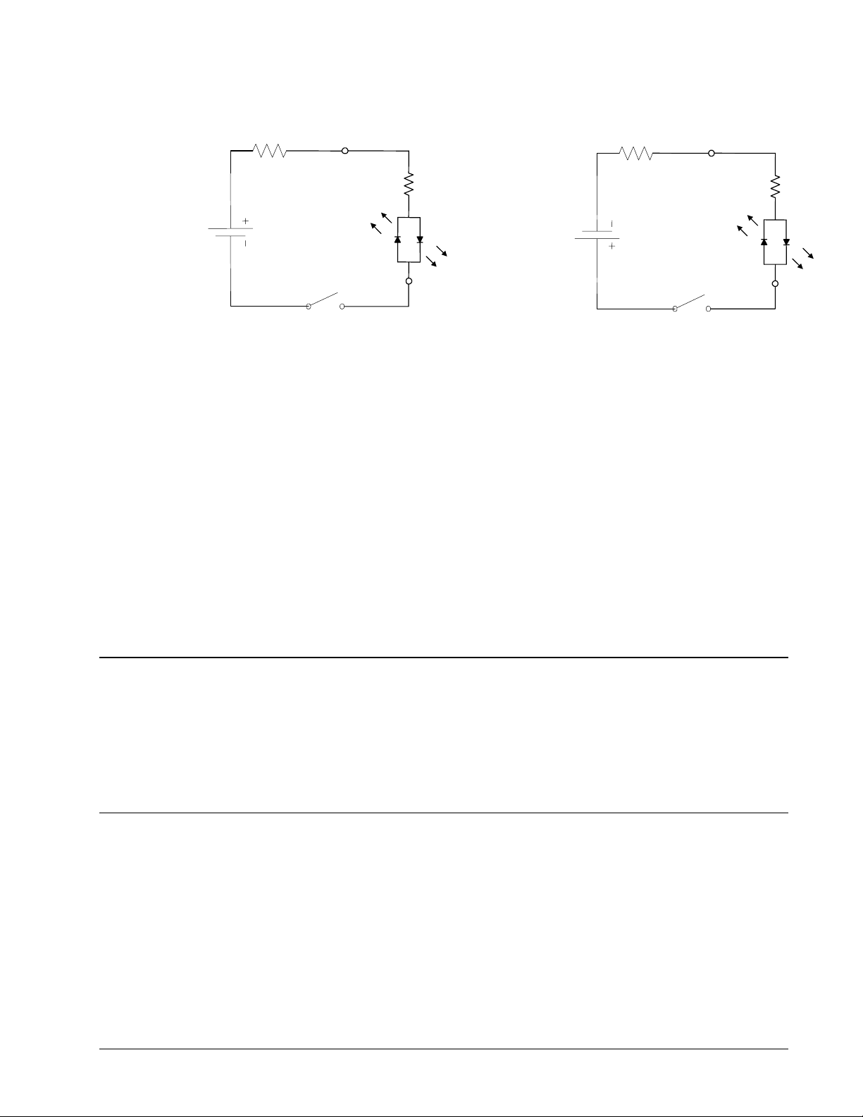
External Resistor Needed for
Voltages > +24V
LSCOM
External Resistor Needed for
Voltages > +24V
LSCOM
Configuration to source current at
LSCOM terminal and sink
switch
Figure 3-2. Connecting a single Limit or Home Switch to an Isolated Supply. This diagram only shows the
connection for the forward limit switch of the X axis.
NOTE: As stated in Chapter 2, the wiring is simplified when using a Galil Interconnect module, such
as the ICM-1900 or ICM-2900. These boards accept the cables of the DMC-2x00 and provide
terminals for easy access (Refer to figure 2-2).
Bypassing the Opto-Isolation:
If no isolation is needed, the internal 5 volt supply may be used to power the switches. This can be
done by connecting a jumper between the pins LSCOM or INCOM and 5V, labeled JP3 on the main
board. The Galil interconnect modules provide jumpers and the DMC-2x00 also provides a jumper for
making this connection.
2.2K
FLSA
2.2K
FLSA
Configuration to sink current at
LSCOM terminal and source
switch
Analog Inputs
The DMC-2x00 has eight analog inputs configured for the range between -10V and 10V. The inputs
are decoded by a 12-bit A/D decoder giving a voltage resolution of approximately .005V. A 16-bit
ADC is available as an option. The impedance of these inputs is 10 KΩ. The analog inputs are
specified as AN[x] where x is a number 1 thru 8.
Amplifier Interface
The DMC-2x00 command voltage ranges between +/-10V. This signal, along with GND, provides the
input to the motor amplifiers. The amplifiers must be sized to drive the motors and load. For best
performance, the amplifiers should be configured for a torque (current) mode of operation with no
additional compensation. The gain should be set such that a 10 volt input results in the maximum
required current.
The DMC-2x00 also provides an amplifier enable signal, AMPEN. This signal changes under the
following conditions: the motor-off command, MO, is given, the watchdog timer activates, or the OE1
DMC-2X00 Chapter 3 Connecting Hardware y 43
Page 54

command (Enable Off-On-Error) is given and the position error exceeds the error limit. As shown in
A
X
A
A
Figure 3-4, AMPEN can be used to disable the amplifier for these conditions.
The standard configuration of the AMPEN signal is TTL active high. In other words, the AMPEN
signal will be high when the controller expects the amplifier to be enabled. The polarity and the
amplitude can be changed if you are using the ICM-2900 interface board. To change the polarity from
active high (5 volts= enable, zero volts = disable) to active low (zero volts = enable, 5 volts= disable),
replace the 7407 IC with a 7406. Note that many amplifiers designate the enable input as ‘inhibit’.
To change the voltage level of the AMPEN signal, note the state of the resistor pack on the ICM-2900.
When Pin 1 is on the 5V mark, the output voltage is 0-5V. To change to 12 volts, pull the resistor pack
and rotate it so that Pin 1 is on the 12 volt side. If you remove the resistor pack, the output signal is an
open collector, allowing the user to connect an external supply with voltages up to 24V.
100-PIN
HIGH
DENSITY
CABLE
7407 Open Collector Buffer.
The Enable can be inverted
by using a 7406. Accessed
by removing ICM-2900
cover.
ICM-2900DMC-2x00
Connection to +5V or +12V made resistor
+5V+12V
pack RP1. Removing the resistor allows
the user to connect their own resistor the
desired voltage level (Up to 24V) by
removing ICM-2900 cover
MPEN
GND
MOCMDX
nalog Switch
SERVO MOTOR
MPLIFIER
Figure 3-3 Connecting AMPEN to the motor amplifier
TTL Inputs
The Auxiliary Encoder Inputs
The auxiliary encoder inputs can be used for general use. For each axis, the controller has one
auxiliary encoder and each auxiliary encoder consists of two inputs, channel A and channel B. The
auxiliary encoder inputs are mapped to the inputs 81-96.
44 • Chapter 3 Connecting Hardware DMC-2X00
Page 55

Each input from the auxiliary encoder is a differential line receiver and can accept voltage levels
between +/- 12 volts. The inputs have been configured to accept TTL level signals. To connect TTL
signals, simply connect the signal to the + input and leave the - input disconnected. For other signal
levels, the - input should be connected to a voltage that is ½ of the full voltage range (for example,
connect the - input to 6 volts if the signal is a 0 - 12 volt logic).
Example:
A DMC-2x10 has one auxiliary encoder. This encoder has two inputs (channel A and channel B).
Channel A input is mapped to input 81 and Channel B input is mapped to input 82. To use this input
for 2 TTL signals, the first signal will be connected to AA+ and the second to AB+. AA- and ABwill be left unconnected. To access this input, use the function @IN[81] and @IN[82].
NOTE: The auxiliary encoder inputs are not available for any axis that is configured for
stepper motor.
TTL Outputs
2x80
The DMC-2x00 provides dedicated and general use outputs.
General Use Outputs
The DMC-2x00 provides eight general use outputs, an output compare and an error signal output. The
general use outputs are TTL and are accessible through the ICM-2900 as OUT1 thru OUT8. These
outputs can be turned On and Off with the commands, SB (Set Bit), CB (Clear Bit), OB (Output Bit),
and OP (Output Port). For more information about these commands, see the Command Summary.
The value of the outputs can be checked with the operand _OP and the function @OUT[] (see Chapter
7, Mathematical Functions and Expressions).
Controllers with 5 or more axes have an additional eight general use TTL outputs.
NOTE: The ICM-2900 has an option to provide opto-isolation on the outputs. In this case, the user
provides an isolated power supply (+5volts to +24volts and ground). For more information, consult
Galil.
Output Compare
The output compare signal is TTL and is available on the ICM-2900 as CMP. Output compare is
controlled by the position of any of the main encoders on the controller. The output can be
programmed to produce an active low pulse (1usec) based on an incremental encoder value or to
activate once when an axis position has been passed. For further information, see the command OC in
the Command Reference.
DMC-2X00 Chapter 3 Connecting Hardware y 45
Page 56

Error Output
The controller provides a TTL signal, ERROR, to indicate a controller error condition. When an error
condition occurs, the ERROR signal will go low and the controller LED will go on. An error occurs
because of one of the following conditions:
1. At least one axis has a position error greater than the error limit. The error limit is set by
using the command ER.
2. The reset line on the controller is held low or is being affected by noise.
3. There is a failure on the controller and the processor is resetting itself.
4. There is a failure with the output IC which drives the error signal.
Extended I/O of the DMC-2x00 Controller
The DMC-2x00 controller offers 64 extended TTL I/O points which can be configured as inputs or
outputs in 8 bit increments. Configuration is accomplished with command CO - see Chapter 7. The
I/O points are accessed through the 80 pin high density connector labeled EXTENDED I/O.
Interfacing to Grayhill or OPTO-22 G4PB24:
The DMC-2x00 controller uses one 80 Pin high density connector to access the extended I/O. This
connector is accessed via the Galil CABLE-80. The Galil CABLE-80 can be converted to (2) 50 pin
ribbon cables which are compatible with I/O mounting racks such as Grayhill 70GRCM32-HL and
OPTO-22 G4PB24. To convert the 80 pin cable, use the CB-50-80 adapter from Galil. The 50 pin
ribbon cables which connect to the CB-50-80 connect directly into the I/O mounting racks. The CB50-80 adapter board is described in the appendix.
When using the OPTO-22 G4PB24 I/O mounting rack, the user will only have access to 48 of the 64
I/O points available on the controller. Block 5 and Block 9 must be configured as inputs and will be
grounded by the I/O rack.
46 • Chapter 3 Connecting Hardware DMC-2X00
Page 57

Chapter 4 Communication
Introduction
The DMC-2x00 has two RS232 ports, and either one USB input port and 2 USB output ports, or
Ethernet ports. The main RS-232 port is the data set and can be configured through the switches on the
front panel. The auxiliary RS-232 port is the data term and can be configured with the software
command CC. The auxiliary RS-232 port can be configured either for daisy chain operation (DMC2000 only) or as a general port. This configuration can be saved using the Burn (BN) instruction. The
RS232 ports also have a clock synchronizing line that allows synchronization of motion on more than
one controller.
RS232 Ports
The RS232 pin-out description for the main and auxiliary port is given below. Note that the auxiliary
port is essentially the same as the main port except inputs and outputs are reversed. The DMC-2x00
may also be configured by the factory for RS422. These pin-outs are also listed below.
NOTE: If you are connecting the RS232 auxiliary port to a terminal or any device which is a
DATASET, it is necessary to use a connector adapter, which changes a dataset to a dataterm. This
cable is also known as a 'null' modem cable.
RS232 - Main Port {P1} DATATERM
1 CTS – output 6 CTS - output
2 Transmit Data - output 7 RTS - input
3 Receive Data - input 8 CTS - output
4 RTS – input 9 No connect (Can connect to +5V or sample clock)
5 Ground
RS232 - Auxiliary Port {P2} DATASET
1 CTS – input 6 CTS - input
2 Transmit Data - input 7 RTS - output
3 Receive Data - output 8 CTS - input
4 RTS – output 9 5V (Can be connected to sample clock with jumpers)
5 Ground
2 • Chapter 4 Communication DMC-2X00
Page 58

*RS422 - Main Port {P1}
1 CTS - output 6 CTS+ output
2 Transmit Data - output 7 Transmit+ output
3 Receive Data - input 8 Receive+ input
4 RTS - input 9 RTS+ input
5 Ground
*RS422 - Auxiliary Port {P2}
1 CTS - input 6 CTS+ input
2 Receive Data - input 7 Receive+ input
3 Transmit Data - output 8 Transmit+ output
4 RTS - output 9 RTS+ output
5 Ground
*Default configuration is RS232. RS422 configuration available from factory.
RS-232 Configuration
Configure your PC for 8-bit data, one start-bit, one stop-bit, full duplex and no parity. The baud rate
for the RS232 communication can be selected by setting the proper switch configuration on the front
panel according to the table below.
Baud Rate Selection
SWITCH SETTINGS
9600 19.2 3800 BAUD RATE
ON ON OFF 1200
ON OFF OFF 9600
OFF ON OFF 19200
OFF OFF ON 38400
OFF ON ON 115200
Handshaking Modes
The RS232 main port can be configured for hardware and software handshaking. For Hardware
Handshaking, set the HSHK switch to ON. In this mode, the RTS and CTS lines are used. The CTS
line will go high whenever the DMC-2x00 is not ready to receive additional characters. The RTS line
will inhibit the DMC-2x00 from sending additional characters. Note, the RTS line goes high for
inhibit. The handshake should be turned on to ensure proper communication especially at higher baud
rates.
Software handshaking can be enabled by setting the XON switch to ON. In this mode, the controller
will generate / accept XON and XOFF characters to control the flow of characters to / from the
terminal. The controller uses the hex value $13 for the XOFF character and the hex value $11 for the
XON character.
The auxiliary port of the DMC-2x00 can be configured either as a general port or for the daisy-chain
(DMC-2000 only). When configured as a general port, the port can be commanded to send ASCII
messages to another DMC-2x00 controller or to a display terminal or panel.
DMC-2X00 Chapter 4 Communication y 3
Page 59

(Configure Communication) at port 2. The command is in the format of:
CC m,n,r,p
where m sets the baud rate, n sets for either handshake or non-handshake mode, r sets for general port
or the auxiliary port, and p turns echo on or off.
m - Baud Rate - 300,1200,4800,9600,19200,38400
n - Handshake - 0=No; 1=Yes
r - Mode - 0=General Port; 1=Daisy-chain
p - Echo - 0=Off; 1=On; Valid only if r=0
Note, for the handshake of the auxiliary port, the roles for the RTS and CTS lines are reversed.
Example:
CC 1200,0,0,1
Configure auxiliary communication port for 1200 baud, no handshake, general
port mode and echo turned on.
Daisy-Chaining (DMC-2000 only)
Up to eight DMC-2000 controllers may be connected in a daisy-chain allowing for multiple controllers
to be commanded from a single serial port. One DMC-2000 is connected to the host terminal via the
RS232 at port 1 or the main port. Port 2 or the auxiliary port of that DMC-2000 is then brought into
port 1 of the next DMC-2000, and so on. The address of each DMC-2000 is configured by setting the
three address dipswitches (A0, A1, A2) located on the front of the controller.
When connecting multiple controllers in a daisy-chain, the cable between controllers should be female
on both ends with all wires connected straight through.
0
ADR1 represents the 2
bit, ADR2 represents 21 bit, and ADR4 represents 22 bit of the address. The
eight possible addresses, 0 through 7, are set as follows:
A2 A1 A0 ADDRESS
OFF OFF OFF 0
OFF OFF ON 1
OFF ON OFF 2
OFF ON ON 3
ON OFF OFF 4
ON OFF ON 5
ON ON OFF 6
ON ON ON 7
To communicate with any one of the DMC-2000 units, give the command “%A”, where A is the
address of the board. All instructions following this command will be sent only to the board with that
address. Only when a new %A command is given will the instruction be sent to another board. The
only exception is "!" command. To talk to all the DMC-2000 boards in the daisy-chain at one time,
insert the character "!" before the software command. All boards receive the command, but only
address 0 will echo.
NOTE: The CC command must be specified to configure the port P2 of each unit.
4 • Chapter 4 Communication DMC-2X00
Page 60

Example- Daisy Chain
Objective: Control a 7-axis motion system using two controllers, a DMC-2040 4 axis controller and a
DMC-2030 3 axis controller. Address 0 is the DMC-2040 and address 1 is the DMC-2030.
Desired motion profile:
Address 0 (DMC-2040) A Axis is 500 counts
B Axis is 1000 counts
C Axis is 2000 counts
D Axis is 1500 counts
Address 1 (DMC-2030) A Axis is 700 counts
B Axis is 1500 counts
C Axis is 2500 counts
Command Interpretation
%0 Talk only to controller 0 (DMC-2040)
PR 500,1000,2000,1500 Specify A,B,C,D distances
%1 Talk only to controller board 1 (DMC-2030)
PR 700,1500,2500 Specify A,B,C distances
!BG Begin motion on both controllers
Synchronizing Sample Clocks in Daisy Chain
It is possible to synchronize the sample clocks of all DMC-2000's in the daisy-chain. The first
controller (connected to the computer) should have a jumper placed on the jumper JP3 to connect the
pins labeled S and 8. Note that this connection requires a jumper to be placed sideways. The
subsequent controllers should have jumpers placed on the jumper JP3, JP4 to connect the pins labeled
S and 8 on both jumpers. Note that these connections require the jumpers to be placed sideways.
Ethernet Configuration (DMC-2100/2200 only)
Communication Protocols
The Ethernet is a local area network through which information is transferred in units known as
packets. Communication protocols are necessary to dictate how these packets are sent and received.
The DMC-2100 supports two industry standard protocols, TCP/IP and UDP/IP. The controller will
automatically respond in the format in which it is contacted.
TCP/IP is a "connection" protocol. The master must be connected to the slave in order to begin
communicating. Each packet sent is acknowledged when received. If no acknowledgement is
received, the information is assumed lost and is resent.
Unlike TCP/IP, UDP/IP does not require a "connection". This protocol is similar to communicating
via RS232. If information is lost, the controller does not return a colon or question mark. Because the
protocol does not provide for lost information, the sender must re-send the packet.
DMC-2X00 Chapter 4 Communication y 5
Page 61
Although UDP/IP is more efficient and simple, Galil recommends using the TCP/IP protocol. TCP/IP
insures that if a packet is lost or destroyed while in transit, it will be resent.
Ethernet communication transfers information in ‘packets’. The packets must be limited to 470 data
bytes or less. Larger packets could cause the controller to lose communication.
NOTE: In order not to lose information in transit, Galil recommends that the user wait for an
acknowledgement of receipt of a packet before sending the next packet.
There are four LEDs provided for the status of Ethernet connection. The representation of LED status
is given below.
LED Status
F Uses Fiber Link
C Uses Full Duplex – will blink when a collision Uses Full Duplex – will blink when a collision occurs with half
duplex
L Ethernet link established – will blink for any activity
100 Uses 100Base T speed Ethernet
Addressing
There are three levels of addresses that define Ethernet devices. The first is the Ethernet or hardware
address. This is a unique and permanent 6 byte number. No other device will have the same Ethernet
address. The DMC-2100/2200 Ethernet address is set by the factory and the last two bytes of the
address are the serial number of the controller.
The second level of addressing is the IP address. This is a 32-bit (or 4 byte) number. The IP address is
constrained by each local network and must be assigned locally. Assigning an IP address to the
controller can be done in a number of ways.
The first method is to use the BOOT-P utility via the Ethernet connection (the DMC-2100/2200 must
be connected to network and powered). For a brief explanation of BOOT-P, see the section: Third
Party Software. Either a BOOT-P server on the internal network or the Galil terminal software may be
used. To use the Galil BOOT-P utility, select the registry in the terminal emulator. Select the DMC2100/2200 and then the Ethernet Parameters tab. Enter the IP address at the prompt and select either
TCP/IP or UDP/IP as the protocol. When done, click on the ASSIGN IP ADDRESS. The Galil
Terminal Software will respond with a list of all controllers on the network that do not currently have
IP addresses. The user selects the controller and the software will assign the controller the specified IP
address. Then enter the terminal and type in BN to save the IP address to the controller's non-volatile
memory.
CAUTION: Be sure that there is only one BOOT-P server running. If your network has DHCP or
BOOT-P running, it may automatically assign an IP address to the controller upon linking it to the
network. In order to ensure that the IP address is correct, please contact your system administrator
before connecting the controller to the Ethernet network.
6 • Chapter 4 Communication DMC-2X00
Page 62

The second method for setting an IP address is to send the IA command through the DMC-2100/2200
main RS-232 port. The IP address you want to assign may be entered as a 4 byte number delimited by
commas (industry standard uses periods) or a signed 32 bit number (Ex. IA 124,51,29,31 or IA
2083724575). Type in BN to save the IP address to the controller's non-volatile memory.
NOTE: Galil strongly recommends that the IP address selected is not one that can be accessed across
the Gateway. The Gateway is an application that controls communication between an internal network
and the outside world.
The third level of Ethernet addressing is the UDP or TCP port number. The Galil controller does not
require a specific port number. The port number is established by the client or master each time it
connects to the controller.
DMC-2X00 Chapter 4 Communication y 7
Page 63

Communicating with Multiple Devices
The DMC-2100/2200 is capable of supporting multiple masters and slaves. The masters may be
multiple PC's that send commands to the controller. The slaves are typically peripheral I/O devices
that receive commands from the controller.
NOTE: The term "Master" is equivalent to the internet "client". The term "Slave" is equivalent to the
internet "server".
An Ethernet handle is a communication resource within a device. The DMC-2100/2200 can have a
maximum of 6 Ethernet handles open at any time. When using TCP/IP, each master or slave uses an
individual Ethernet handle. In UDP/IP, one handle may be used for all the masters, but each slave uses
one. (Pings and ARPs do not occupy handles.) If all 6 handles are in use and a 7
connect, it will be sent a "reset packet" that generates the appropriate error in its windows application.
NOTE: There are a number of ways to reset the controller. Hardware reset (push reset button or
power down controller) and software resets (through Ethernet or RS232 by entering RS). The only
reset that will not cause the controller to disconnect is a software reset via the Ethernet.
When the Galil controller acts as the master, the IH command is used to assign handles and connect to
its slaves. The IP address may be entered as a 4 byte number separated with commas (industry
standard uses periods) or as a signed 32 bit number. A port number may also be specified, but if it is
not, it will default to 1000. The protocol (TCP/IP or UDP/IP) to use must also be designated at this
time. Otherwise, the controller will not connect to the slave. (Ex. IHB=151,25,255,9<179>2 This
will open handle #2 and connect to the IP address 151.25.255.9, port 179, using TCP/IP)
An additional protocol layer is available for speaking to I/O devices. Modbus is an RS-485 protocol
that packages information in binary packets that are sent as part of a TCP/IP packet. In this protocol,
each slave has a 1 byte slave address. The DMC-2100/2200 can use a specific slave address or default
to the handle number. The port number for Modbus is 502.
th
master tries to
The Modbus protocol has a set of commands called function codes. The DMC-2100/2200 supports the
10 major function codes:
Function Code Definition
01 Read Coil Status (Read Bits)
02 Read Input Status (Read Bits)
03 Read Holding Registers (Read Words)
04 Read Input Registers (Read Words)
05 Force Single Coil (Write One Bit)
06 Preset Single Register (Write One Word)
07 Read Exception Status (Read Error Code)
15 Force Multiple Coils (Write Multiple Bits)
16 Preset Multiple Registers (Write Words)
17 Report Slave ID
The DMC-2100/2200 provides three levels of Modbus communication. The first level allows the user
to create a raw packet and receive raw data. It uses the MBh command with a function code of –1.
The format of the command is
8 • Chapter 4 Communication DMC-2X00
Page 64

MBh = -1,len,array[] where len is the number of bytes
array[] is the array with the data
The second level incorporates the Modbus structure. This is necessary for sending configuration and
special commands to an I/O device. The formats vary depending on the function code that is called.
For more information refer to the Command Reference.
The third level of Modbus communication uses standard Galil commands. Once the slave has been
configured, the commands that may be used are @IN[], @AN[], SB, CB, OB, and AO. For example,
AO 2020,8.2 would tell I/O number 2020 to output 8.2 volts.
If a specific slave address is not necessary, the I/O number to be used can be calculated with the
following:
I/O Number = (HandleNum*1000) + ((Module-1)*4) + (BitNum-1)
Where HandleNum is the handle number from 1 (A) to 6 (F). Module is the position of the module in
the rack from 1 to 16. BitNum is the I/O point in the module from 1 to 4.
If an explicit slave address is to be used, the equation becomes:
I/O Number = (SlaveAddress*10000) + (HandleNum*1000) +((Module-1)*4) + (Bitnum-1)
To view an example procedure for communicating with an OPTO-22 rack, refer to the appendix.
Which devices receive what information from the controller depends on a number of things. If a
device queries the controller, it will receive the response unless it explicitly tells the controller to send
it to another device. If the command that generates a response is part of a downloaded program, the
response will route to whichever port is specified as the default (unless explicitly told to go to another
port) with the ENET switch ("ON" designates Ethernet in which case it goes to the last handle to
communicate with the controller, "OFF" designates main RS232). To designate a specific destination
for the information, add {Eh} to the end of the command. (Ex. MG{EC}"Hello" will send the
message "Hello" to handle #3. TP,,?{EF} will send the z axis position to handle #6.)
Multicasting
A multicast may only be used in UDP/IP and is similar to a broadcast (where everyone on the network
gets the information) but specific to a group. In other words, all devices within a specified group will
receive the information that is sent in a multicast. There can be many multicast groups on a network
and are differentiated by their multicast IP address. To communicate with all the devices in a specific
multicast group, the information can be sent to the multicast IP address rather than to each individual
device IP address. All Galil controllers belong to a default multicast address of 239.255.19.56. The
controller's multicast IP address can be changed by using the IA> u command.
Using Third Party Software
Galil supports ARP, BOOT-P, and Ping which are utilities for establishing Ethernet connections. ARP
is an application that determines the Ethernet (hardware) address of a device at a specific IP address.
BOOT-P is an application that determines which devices on the network do not have an IP address and
assigns the IP address you have chosen to it. Ping is used to check the communication between the
device at a specific IP address and the host computer.
The DMC-2100 can communicate with a host computer through any application that can send TCP/IP
or UDP/IP packets. A good example of this is Telnet, a utility that comes with most Windows
systems.
DMC-2X00 Chapter 4 Communication y 9
Page 65

Data Record
The DMC-2x00 can provide a block of status information with the use of a single command, QR. This
command, along with the QZ command can be very useful for accessing complete controller status.
The QR command will return 4 bytes of header information and specific blocks of information as
specified by the command arguments:
QR ABCDEFGHST
Each argument corresponds to a block of information according to the Data Record Map below. If no
argument is given, the entire data record map will be returned. Note that the data record size will
depend on the number of axes.
Data Record Map
DATA TYPE ITEM BLOCK
UB 1st byte of header Header
UB 2
UB 3
UB 4
UW sample number I block
UB general input 0 I block
UB general input 1 I block
UB general input 2 I block
UB general input 3 I block
UB general input 4 I block
UB general input 5 I block
UB general input 6 I block
UB general input 7 I block
UB general input 8 I block
UB general input 9 I block
UB general output 0 I block
UB general output 1 I block
UB general output 2 I block
UB general output 3 I block
UB general output 4 I block
UB general output 5 I block
UB general output 6 I block
UB general output 7 I block
UB general output 8 I block
UB general output 9 I block
UB error code I block
UB general status I block
UW segment count of coordinated move for S plane S block
UW coordinated move status for S plane S block
SL distance traveled in coordinated move for S plane S block
UW segment count of coordinated move for T plane T block
UW coordinated move status for T plane T block
nd
byte of header Header
rd
byte of header Header
rth
byte of header Header
10 • Chapter 4 Communication DMC-2X00
Page 66

SL distance traveled in coordinated move for T plane T block
UW a axis status A block
UB a axis switches A block
UB a axis stop code A block
SL a axis reference position A block
SL a axis motor position A block
SL a axis position error A block
SL a axis auxiliary position A block
SL a axis velocity A block
SW a axis torque A block
SW a axis analog A block
UW b axis status B block
UB b axis switches B block
UB b axis stop code B block
SL b axis reference position B block
SL b axis motor position B block
SL b axis position error B block
SL b axis auxiliary position B block
SL b axis velocity B block
SW b axis torque B block
SW b axis analog B block
UW c axis status C block
UB c axis switches C block
UB c axis stop code C block
SL c axis reference position C block
SL c axis motor position C block
SL c axis position error C block
SL c axis auxiliary position C block
SL c axis velocity C block
SW c axis torque C block
SW c axis analog C block
UW d axis status D block
UB d axis switches D block
UB d axis stop code D block
SL d axis reference position D block
SL d axis motor position D block
SL d axis position error D block
SL d axis auxiliary position D block
SL d axis velocity D block
SW d axis torque D block
SW d axis analog D block
UW e axis status E block
UB e axis switches E block
UB e axis stop code E block
SL e axis reference position E block
DMC-2X00 Chapter 4 Communication y 11
Page 67

SL e axis motor position E block
SL e axis position error E block
SL e axis auxiliary position E block
SL e axis velocity E block
SW e axis torque E block
SW e axis analog E block
UW f axis status F block
UB f axis switches F block
UB f axis stop code F block
SL f axis reference position F block
SL f axis motor position F block
SL f axis position error F block
SL f axis auxiliary position F block
SL f axis velocity F block
SW f axis torque F block
SW f axis analog F block
UW g axis status G block
UB g axis switches G block
UB g axis stop code G block
SL g axis reference position G block
SL g axis motor position G block
SL g axis position error G block
SL g axis auxiliary position G block
SL g axis velocity G block
SW g axis torque G block
SW g axis analog G block
UW h axis status H block
UB h axis switches H block
UB h axis stop code H block
SL h axis reference position H block
SL h axis motor position H block
SL h axis position error H block
SL h axis auxiliary position H block
SL h axis velocity H block
SW h axis torque H block
SW h axis analog H block
NOTE: UB = Unsigned Byte, UW = Unsigned Word, SW = Signed Word, SL = Signed Long Word
Explanation of Status Information and Axis Switch Information
Header Information - Byte 0, 1 of Header:
BIT 15 BIT 14 BIT 13 BIT 12 BIT 11 BIT 10 BIT 9 BIT 8
1 N/A N/A N/A N/A I Block
Present
12 • Chapter 4 Communication DMC-2X00
T Block
Present
S Block
Present
Page 68

in Data
Record
BIT 7 BIT 6 BIT 5 BIT 4 BIT 3 BIT 2 BIT 1 BIT 0
in Data
Record
in Data
Record
H Block
Present
in Data
Record
G Block
Present
in Data
Record
F Block
Present
in Data
Record
E Block
Present
in Data
Record
D Block
Present
in Data
Record
C Block
Present
in Data
Record
B Block
Present
in Data
Record
Bytes 2, 3 of Header:
Bytes 2 and 3 make a word which represents the Number of bytes in the data record, including the
header.
Byte 2 is the low byte and byte 3 is the high byte
NOTE: The header information of the data records is formatted in little endian.
General Status Information (1 Byte)
BIT 7 BIT
6
Program
Running
N/A N/A N/A N/A Waiting for
BIT
5
BIT
4
BIT
3
BIT 2 BIT 1 BIT 0
Trace On Echo On
input from IN
command
A Block
Present
in Data
Record
Axis Switch Information (1 Byte)
BIT 7 BIT 6 BIT 5 BIT 4 BIT 3 BIT 2 BIT 1 BIT 0
Latch
Occurred
State of
Latch
Input
N/A N/A State of
Axis Status Information (2 Byte)
BIT 15 BIT 14 BIT 13 BIT 12 BIT 11 BIT 10 BIT 9 BIT 8
Move in
Progress
BIT 7 BIT 6 BIT 5 BIT 4 BIT 3 BIT 2 BIT 1 BIT 0
Negative
Direction
Move
Mode of
Motion
PA or
PR
Mode of
Motion
Contour
Mode of
Motion
PA only
Motion
is
slewing
(FE)
Find
Edge in
Progress
Motion is
stopping
due to ST
or Limit
Forward
Limit
Home
(HM) in
Progress
Motion is
making
final
decel.
State of
Reverse
Limit
1st Phase
of HM
complete
Latch is
armed
State of
Home
Input
2nd Phase
of HM
complete
FI
or
command
issued
Off-OnError
armed
SM
Jumper
Installed
Mode of
Motion
Coord.
Motion
Motor
Off
DMC-2X00 Chapter 4 Communication y 13
Page 69

Switch
Coordinated Motion Status Information for S or T plane (2 Byte)
BIT 15 BIT
14
BIT 13 BIT 12 BIT 11 BIT
10
BIT 9 BIT 8
Move in
Progress
BIT 7 BIT 6 BIT 5 BIT 4 BIT 3 BIT 2 BIT 1 BIT 0
N/A N/A Motion is
N/A N/A N/A N/A N/A N/A N/A
slewing
Motion is
stopping due
to ST or
Limit
Switch
Motion is
making
final
decel.
N/A N/A N/A
Notes Regarding Velocity and Torque Information
The velocity information that is returned in the data record is 64 times larger than the value returned
when using the command TV (Tell Velocity). See command reference for more information about
TV.
The Torque information is represented as a number in the range of +/-32767. Maximum negative
torque is -32767. Maximum positive torque is 32767. Zero torque is 0.
QZ Command
The QZ command can be very useful when using the QR command, since it provides information
about the controller and the data record. The QZ command returns the following 4 bytes of
information.
BYTE # INFORMATION
0 Number of axes present
1 number of bytes in general block of data record
2 number of bytes in coordinate plane block of data record
3 Number of Bytes in each axis block of data record
Controller Response to Commands
Most DMC-2x00 instructions are represented by two characters followed by the appropriate
parameters. Each instruction must be terminated by a carriage return or semicolon.
Instructions are sent in ASCII, and the DMC-2x00 decodes each ASCII character (one byte) one at a
time. It takes approximately 0.5 msec for the controller to decode each command. However, the PC
can send data to the controller at a much faster rate because of the FIFO buffer.
After the instruction is decoded, the DMC-2x00 returns a response to the port from which the
command was generated. If the instruction was valid, the controller returns a colon (:) or a question
mark (?) if the instruction was not valid. For example, the controller will respond to commands which
are sent via the USB port back through the USB port, to commands which are sent via the main RS232 port back through the RS-232 port, and to commands which are sent via the Ethernet port back
through the Ethernet port.
14 • Chapter 4 Communication DMC-2X00
Page 70

For instructions that return data, such as Tell Position (TP), the DMC-2x00 will return the data
followed by a carriage return, line feed and : .
It is good practice to check for : after each command is sent to prevent errors. An echo function is
provided to enable associating the DMC-2x00 response with the data sent. The echo is enabled by
sending the command EO 1 to the controller.
Unsolicited Messages Generated by Controller
When the controller is executing a program, it may generate responses which will be sent via the USB
port (DMC-2000), main RS-232 port, or Ethernet ports (DMC-2100/2200). This response could be
generated as a result of messages using the MG or IN command OR
These responses are known as unsolicited messages since they are not generated as the direct response
to a command.
Messages can be directed to a specific port using the specific Port arguments - see MG and IN
commands described in the Command Reference. If the port is not explicitly given, unsolicited
messages will be sent to the default port. The default port is determined by the state of the
USB/Ethernet dip switch when the system is reset.
The controller has a special command, CW, which can affect the format of unsolicited messages. This
command is used by Galil Software to differentiate response from the command line and unsolicited
messages. The command, CW1 causes the controller to set the high bit of ASCII characters to 1 of all
unsolicited characters. This may cause characters to appear garbled to some terminals. This function
can be disabled by issuing the command, CW2. For more information, see the CW command in the
Command Reference.
as a result of a command error.
When handshaking is used (hardware and/or software handshaking) characters which are generated by
the controller are placed in a FIFO buffer before they are sent out of the controller. This size of the
USB buffer is 64 bytes and the size of the RS-232 buffer is 128 bytes. When this buffer becomes full,
the controller must either stop executing commands or ignore additional characters generated for
output. The command CW,1 causes the controller to ignore all output from the controller while the
FIFO is full. The command, CW ,0 causes the controller to stop executing new commands until more
room is made available in the FIFO. This command can be very useful when hardware handshaking is
being used and the communication line between controller and terminal will be disconnected. In this
case, characters will continue to build up in the controller until the FIFO is full. For more information,
see the CW command in the Command Reference.
Galil Software Tools and Libraries
API (Application Programming Interface) software is available from Galil. The API software is
written in C and is included in the Galil CD-ROM. They can be used for development under
Windows environments. With the API's, the user can incorporate already existing library functions
directly into a C program.
Galil has also developed a Visual Basic Toolkit. This provides 32-bit OCXs for handling all of the
DMC-2x00 communications including support of interrupts. These objects install directly into Visual
Basic and are part of the run-time environment.
Galil also has an Active-X Tool Kit to allow developers to rapidly develop their own user applications.
For more information, contact Galil.
DMC-2X00 Chapter 4 Communication y 15
Page 71

Chapter 5 Command Basics
Introduction
The DMC-2x00 provides over 100 commands for specifying motion and machine parameters.
Commands are included to initiate action, interrogate status and configure the digital filter. These
commands can be sent in ASCII or binary.
In ASCII, the DMC-2x00 instruction set is BASIC-like and easy to use. Instructions consist of two
uppercase letters that correspond phonetically with the appropriate function. For example, the
instruction BG begins motion, and ST stops the motion. In binary, commands are represented by a
binary code ranging from 80 to FF.
ASCII commands can be sent "live" over the bus for immediate execution by the DMC-2x00, or an
entire group of commands can be downloaded into the DMC-2x00 memory for execution at a later
time. Combining commands into groups for later execution is referred to as Applications
Programming and is discussed in the following chapter. Binary commands cannot be used in
Applications programming.
This section describes the DMC-2x00 instruction set and syntax. A summary of commands as well as
a complete listing of all DMC-2x00 instructions is included in the Command Reference chapter.
Command Syntax - ASCII
DMC-2x00 instructions are represented by two ASCII upper case characters followed by applicable
arguments. A space may be inserted between the instruction and arguments. A semicolon or <return>
is used to terminate the instruction for processing by the DMC-2x00 command interpreter.
NOTE: If you are using a Galil terminal program, commands will not be processed until an <return>
command is given. This allows the user to separate many commands on a single line and not begin
execution until the user gives the <return> command.
IMPORTANT: All DMC-2x00 commands are sent in upper case.
For example, the command
PR 4000 <return> Position relative
PR is the two character instruction for position relative. 4000 is the argument which represents the
required position value in counts. The <return> terminates the instruction. The space between PR and
4000 is optional.
For specifying data for the A,B,C and D axes, commas are used to separate the axes. If no data is
specified for an axis, a comma is still needed as shown in the examples below. If no data is specified
for an axis, the previous value is maintained.
16 • Chapter 5 Command Basics DMC-2X00
Page 72

To view the current values for each command, type the command followed by a ? for each axis
requested.
PR 1000 Specify A only as 1000
PR ,2000 Specify B only as 2000
PR ,,3000 Specify C only as 3000
PR ,,,4000 Specify D only as 4000
PR 2000, 4000,6000, 8000 Specify A,B,C and D
PR ,8000,,9000 Specify B and D only
PR ?,?,?,? Request A,B,C,D values
PR ,? Request B value only
The DMC-2x00 provides an alternative method for specifying data. Here data is specified individually
using a single axis specifier such as A, B, C or D. An equals sign is used to assign data to that axis.
For example:
PRA=1000 Specify a position relative movement for the A axis of 1000
ACB=200000 Specify acceleration for the B axis as 200000
Instead of data, some commands request action to occur on an axis or group of axes. For example, ST
AB stops motion on both the A and B axes. Commas are not required in this case since the particular
axis is specified by the appropriate letter A, B, C or D. If no parameters follow the instruction, action
will take place on all axes. Here are some examples of syntax for requesting action:
BG A Begin A only
BG B Begin B only
BG ABCD Begin all axes
BG BD Begin B and D only
BG Begin all axes
2x80
For controllers with 5 or more axes, the axes are referred to as A,B,C,D,E,F,G,H.
BG ABCDEFGH Begin all axes
BG D Begin D only
Coordinated Motion with more than 1 axis
When requesting action for coordinated motion, the letter S and T are used to specify coordinated
motion planes. For example:
BG S Begin coordinated sequence, S
BG TW Begin coordinated sequence, T, and D axis
DMC-2X00 Chapter 5 Command Basics y 17
Page 73

Command Syntax - Binary
Some commands have an equivalent binary value. Binary communication mode can be executed much
faster than ASCII commands. Binary format can only be used when commands are sent from the PC
and cannot be embedded in an application program.
Binary Command Format
All binary commands have a 4 byte header and is followed by data fields. The 4 bytes are specified in
hexadecimal format.
Header Format:
Byte 1
Specifies the command number between 80 to FF. The complete binary command number table is
listed below.
Byte 2
Specifies the # of bytes in each field as 0,1,2,4 or 6 as follows:
00 No datafields (i.e. SH or BG)
01 One byte per field
02 One word (2 bytes per field)
04 One long word (4 bytes) per field
06 Galil real format (4 bytes integer and 2 bytes fraction)
Byte 3
Specifies whether the command applies to a coordinated move as follows:
00 No coordinated motion movement
01 Coordinated motion movement
For example, the command STS designates motion to stop on a vector motion. The third byte for the
equivalent binary command would be 01.
Byte 4
Specifies the axis # or data field as follows
th
Bit 7 = H axis or 8
Bit 6 = G axis or 7
Bit 5 = F axis or 6
Bit 4 = E axis or 5
Bit 3 = D axis or 4
Bit 2 = C axis or 3
data field
th
data field
th
data field
th
data field
th
data field
rd
data field
18 • Chapter 5 Command Basics DMC-2X00
Page 74

Bit 1 = B axis or 2nd data field
st
Bit 0 = A axis or 1
data field
Datafields Format
Datafields must be consistent with the format byte and the axes byte. For example, the command PR
1000,, -500 would be
A7 02 00 05 03 E8 FE 0C
where A7 is the command number for PR
02 specifies 2 bytes for each data field
00 S is not active for PR
0
05 specifies bit 0 is active for A axis and bit 2 is active for C axis (2
+ 22=5)
03 E8 represents 1000
FE OE represents -500
Example
The command ST ABCS would be
A1 00 01 07
where A1 is the command number for ST
00 specifies 0 data fields
01 specifies stop the coordinated axes S
07 specifies stop X (bit 0), Y (bit 1) and Z (bit 2) 2
Binary Command Table
COMMAND NO. COMMAND NO. COMMAND No.
reserved 80 reserved ab reserved d6
KP 81 reserved ac reserved d7
KI 82 reserved ad RP d8
KD 83 reserved ae TP d9
DV 84 reserved af TE da
AF 85 LM b0 TD db
KF 86 LI b1 TV dc
PL 87 VP b2 RL dd
ER 88 CR a3 TT de
IL 89 TN b4 TS df
TL 8a LE, VE b5 TI e0
MT 8b VT b6 SC e1
CE 8c VA b7 reserved e2
OE 8d VD b8 reserved e3
FL 8e VS b9 reserved e4
BL 8f VR ba TM e5
0+21+23
=7
DMC-2X00 Chapter 5 Command Basics y 19
Page 75

AC 90 reserved bb CN e6
d
DC 91 reserved bc LZ e7
SP 92 CM bd OP e8
IT 93 CD be OB e9
FA 94 DT bf SB ea
FV 95 ET c0 CB eb
GR 96 EM c1 II ec
DP 97 EP c2 EI ed
DE 98 EG c3 AL ee
OF 99 EB c4 reserved ef
GM 9a EQ c5 reserved f0
reserved 9b EC c6 reserved f1
reserved 9c reserved c7 reserved f2
reserved 9d AM c8 reserved f3
reserved 9e MC c9 reserved f4
reserved 9f TW ca reserved f5
BG a0 MF cb reserved f6
ST a1 MR cc reserved f7
AB a2 AD cd reserved f8
HM a3 AP ce reserved f9
FE a4 AR cf reserved fa
FI a5 AS d0 reserved fb
PA a6 AI d1 reserved fc
PR a7 AT d2 reserved fd
JG a8 WT d3 reserved fe
MO a9 WC d4 reserved ff
SH aa reserved d5
Controller Response to DATA
The DMC-2x00 returns a : for valid commands and a ? for invalid commands.
For example, if the command BG is sent in lower case, the DMC-2x00 will return a ?.
:bg <return> invalid command, lower case
? DMC-2x00 returns a ?
When the controller receives an invalid command the user can request the error code. The error code
will specify the reason for the invalid command response. To request the error code type the command
TC1. For example:
?TC1 <return> Tell Code comman
1 Unrecognized
There are many reasons for receiving an invalid command response. The most common reasons are:
unrecognized command (such as typographical entry or lower case), command given at improper time
(such as during motion), or a command out of range (such as exceeding maximum speed). A complete
listing of all codes is listed in the TC command in the Command Reference section.
20 • Chapter 5 Command Basics DMC-2X00
Returned response
Page 76

Interrogating the Controller
Interrogation Commands
The DMC-2x00 has a set of commands that directly interrogate the controller. When the command is
entered, the requested data is returned in decimal format on the next line followed by a carriage return
and line feed. The format of the returned data can be changed using the Position Format (PF), Variable
Format (VF) and Leading Zeros (LZ) command. See Chapter 7 and the Command Reference.
Summary of Interrogation Commands
RP Report Command Position
RL Report Latch
∧R ∧
V
SC Stop Code
TB Tell Status
TC Tell Error Code
TD Tell Dual Encoder
TE Tell Error
TI Tell Input
TP Tell Position
TR Trace
TS Tell Switches
TT Tell Torque
TV Tell Velocity
Firmware Revision Information
For example, the following example illustrates how to display the current position of the X axis:
TP A <return> Tell position A
0000000000 Controllers Response
TP AB <return> Tell position A and B
0000000000,0000000000 Controllers Response
Interrogating Current Commanded Values.
Most commands can be interrogated by using a question mark (?) as the axis specifier. Type the
command followed by a ? for each axis requested.
PR ?,?,?,? Request A,B,C,D values
PR ,? Request B value only
The controller can also be interrogated with operands.
Operands
Most DMC-2x00 commands have corresponding operands that can be used for interrogation.
Operands must be used inside of valid DMC expressions. For example, to display the value of an
operand, the user could use the command:
MG ‘operand’ where ‘operand’ is a valid DMC operand
DMC-2X00 Chapter 5 Command Basics y 21
Page 77

All of the command operands begin with the underscore character (_). For example, the value of the
current position on the A axis can be assigned to the variable ‘V’ with the command:
V=_TPA
The Command Reference denotes all commands which have an equivalent operand as "Used as an
Operand". Also, see description of operands in Chapter 7.
Command Summary
For a complete command summary, see Command Reference manual.
22 • Chapter 5 Command Basics DMC-2X00
Page 78

THIS PAGE LEFT BLANK INTENTIONALLY
DMC-2X00 Chapter 5 Command Basics y 23
Page 79

Chapter 6 Programming Motion
Overview
The DMC-2x00 provides several modes of motion, including independent positioning and jogging,
coordinated motion, electronic cam motion, and electronic gearing. Each one of these modes is
discussed in the following sections.
The DMC-2x10 is a single axis controller and uses A-axis motion only. Likewise, the DMC-2x20 uses
A and B, the DMC-2x30 uses A,B and C, and the DMC-2x40 uses A,B,C and D. The DMC-2x50 uses
A,B,C,D, and E. The DMC-2x60 uses A,B,C,D,E, and F. The DMC-2x70 uses A,B,C,D,E,F and G.
The DMC-2x80 uses the axes A,B,C,D,E,F,G, and H.
The example applications described below will help guide you to the appropriate mode of motion.
Example Application Mode of Motion Commands
Absolute or relative positioning where each axis is
independent and follows prescribed velocity
profile.
Velocity control where no final endpoint is
prescribed. Motion stops on Stop command.
Absolute positioning mode where absolute position
targets may be sent to the controller while the axis
is in motion.
Motion Path described as incremental position
points versus time.
2,3 or 4 axis coordinated motion where path is
described by linear segments.
Independent Axis Positioning PA,PR
SP,AC,DC
Independent Jogging JG
AC,DC
ST
Position Tracking PA, PT
SP
AC, DC
Contour Mode CM
CD
DT
WC
Linear Interpolation LM
LI,LE
VS,VR
VA,VD
24 • Chapter 6 Programming Motion DMC-2X00
Page 80

2-D motion path consisting of arc segments and
linear segments, such as engraving or quilting.
Third axis must remain tangent to 2-D motion path,
such as knife cutting.
Electronic gearing where slave axes are scaled to
master axis which can move in both directions.
Master/slave where slave axes must follow a
master such as conveyer speed.
Moving along arbitrary profiles or mathematically
prescribed profiles such as sine or cosine
trajectories.
Teaching or Record and Play Back
Backlash Correction Dual Loop DV
Following a trajectory based on a master encoder
position
Smooth motion while operating in independent axis
positioning
Smooth motion while operating in vector or linear
interpolation positioning
Smooth motion while operating with stepper
motors
Gantry - two axes are coupled by gantry Gantry Mode GR
Coordinated Motion VM
VP
CR
VS,VR
VA,VD
VE
Coordinated motion with tangent
axis specified
Electronic Gearing GA, GD
Electronic Gearing GA, GD
Contour Mode CM
Contour Mode with Automatic
Array Capture
Electronic Cam EA
Independent Motion Smoothing IT
Vector Smoothing VT
Stepper Motor Smoothing KS
VM
VP
CR
VS,VA,VD
TN
VE
_GP, GR
GM (if gantry)
_GP, GR
CD
DT
WC
CM
CD
DT
WC
RA
RD
RC
EM
EP
ET
EB
EG
EQ
GM
Independent Axis Positioning
In this mode, motion between the specified axes is independent, and each axis follows its own profile.
The user specifies the desired absolute position (PA) or relative position (PR), slew speed (SP),
DMC-2X00 Chapter 6 Programming Motion y 25
Page 81

acceleration ramp (AC), and deceleration ramp (DC), for each axis. On begin (BG), the DMC-2x00
profiler generates the corresponding trapezoidal or triangular velocity profile and position trajectory.
The controller determines a new command position along the trajectory every sample period until the
specified profile is complete. Motion is complete when the last position command is sent by the
DMC-2x00 profiler.
NOTE: The actual motor motion may not be complete when the profile has been completed, however,
the next motion command may be specified.
The Begin (BG) command can be issued for all axes either simultaneously or independently. ABC or
D axis specifiers are required to select the axes for motion. When no axes are specified, this causes
motion to begin on all axes.
The speed (SP) and the acceleration (AC) can be changed at any time during motion; however, the
deceleration (DC) and position (PR or PA) cannot be changed until motion is complete. Remember,
motion is complete when the profiler is finished, not when the actual motor is in position. The Stop
command (ST) can be issued at any time to decelerate the motor to a stop before it reaches its final
position.
An incremental position movement (IP) may be specified during motion as long as the additional move
is in the same direction. Here, the user specifies the desired position increment, n. The new target is
equal to the old target plus the increment, n. Upon receiving the IP command, a revised profile will be
generated for motion towards the new end position. The IP command does not require a BG.
NOTE: If the motor is not moving, the IP command is equivalent to the PR and BG command
combination.
Command Summary - Independent Axis
COMMAND DESCRIPTION
PR A,B,C,D Specifies relative distance
PA A,B,C,D Specifies absolute position
SP A,B,C,D Specifies slew speed
AC A,B,C,D Specifies acceleration rate
DC A,B,C,D Specifies deceleration rate
BG ABCD Starts motion
ST ABCD Stops motion before end of move
IP A,B,C,D Changes position target
IT A,B,C,D Time constant for independent motion smoothing
AM ABCD Trip point for profiler complete
MC ABCD Trip point for "in position"
The DMC-2x00 also allows use of single axis specifiers such as PRB=2000
Operand Summary - Independent Axis
OPERAND DESCRIPTION
_ACx Return acceleration rate for the axis specified by ‘x’
_DCx Return deceleration rate for the axis specified by ‘x’
_SPx Returns the speed for the axis specified by ‘x’
26 • Chapter 6 Programming Motion DMC-2X00
Page 82

_PAx
_PRx Returns current incremental distance specified for the ‘x’ axis
Returns current destination if ‘x’ axis is moving, otherwise returns the current commanded
position if in a move.
Examples
Absolute Position Movement
Instruction Interpretation
PA 10000,20000 Specify absolute A,B position
AC 1000000,1000000 Acceleration for A,B
DC 1000000,1000000 Deceleration for A,B
SP 50000,30000 Speeds for A,B
BG AB Begin motion
Multiple Move Sequence
Required Motion Profiles:
A-Axis 500 counts Position
10000 count/sec Speed
B-Axis 1000 counts Position
15000 count/sec Speed
C-Axis 100 counts Position
5000 counts/sec Speed
500000 counts/sec
500000 counts/sec
500000 counts/sec
2
Acceleration
2
Acceleration
2
Acceleration
This example will specify a relative position movement on A, B and C axes. The movement on each
axis will be separated by 20 msec. Fig. 6.1 shows the velocity profiles for the A,B and C axis.
Instruction Interpretation
#A Begin Program
PR 2000,500,100
SP 15000,10000,5000 Specify speed of 10000, 15000, and 5000 counts / sec
AC 500000,500000,500000 Specify acceleration of 500000 counts / sec
DC 500000,500000,500000 Specify deceleration of 500000 counts / sec
BG A Begin motion on the A axis
WT 20 Wait 20 msec
BG B Begin motion on the B axis
WT 20 Wait 20 msec
BG C Begin motion on C axis
EN End Program
Specify relative position movement of 2000, 500 and 100 counts
for A,B and C axes.
2
for all axes
2
for all axes
DMC-2X00 Chapter 6 Programming Motion y 27
Page 83

VELOCITY
(COUNTS/SEC)
A axis velocity profile
20000
15000
10000
5000
B axis velocity profile
C axis velocity profile
TIME (ms)
0
Figure 6.1 - Velocity Profiles of ABC
Notes on fig 6.1: The A and B axis have a ‘trapezoidal’ velocity profile, while the C axis has a
‘triangular’ velocity profile. The A and B axes accelerate to the specified speed, move at this constant
speed, and then decelerate such that the final position agrees with the command position, PR. The C
axis accelerates, but before the specified speed is achieved, must begin deceleration such that the axis
will stop at the commanded position. All 3 axes have the same acceleration and deceleration rate,
hence, the slope of the rising and falling edges of all 3 velocity profiles are the same.
Position Tracking
The Galil controller may be placed in the position tracking mode to support changing the target of an
absolute position move on the fly. New targets may be given in the same direction or the opposite
direction of the current position target. The controller will then calculate a new trajectory based upon
the new target and the acceleration, deceleration, and speed parameters that have been set. The motion
profile in this mode is trapezoidal. There is not a set limit governing the rate at which the end point
may be changed, however at the standard TM rate, the controller updates the position information at
the rate of 1msec. The controller generates a profiled point every other sample, and linearly
interpolates one sample between each profiled point. Some examples of applications that may use this
mode are satellite tracking, missile tracking, random pattern polishing of mirrors or lenses, or any
application that requires the ability to change the endpoint without completing the previous move.
20
40 60
80
100
The PA command is typically used to command an axis or multiple axes to a specific absolute position.
For some applications such as tracking an object, the controller must proceed towards a target and have
the ability to change the target during the move. In a tracking application, this could occur at any time
during the move or at regularly scheduled intervals. For example if a robot was designed to follow a
moving object at a specified distance and the path of the object wasn’t known the robot would be
required to constantly monitor the motion of the object that it was following. To remain within a
specified distance it would also need to constantly update the position target it is moving towards.
Galil motion controllers support this type of motion with the position tracking mode. This mode will
allow scheduled or random updates to the current position target on the fly. Based on the new target
the controller will either continue in the direction it is heading, change the direction it is moving, or
decelerate to a stop.
28 • Chapter 6 Programming Motion DMC-2X00
Page 84

The position tracking mode shouldn’t be confused with the contour mode. The contour mode allows
the user to generate custom profiles by updating the reference position at a specific time rate. In this
mode, the position can be updated randomly or at a fixed time rate, but the velocity profile will always
be trapezoidal with the parameters specified by AC, DC, and SP. Updating the position target at a
specific rate will not allow the user to create a custom profile.
The following example will demonstrate the possible different motions that may be commanded by the
controller in the position tracking mode. In this example, there is a host program that will generate the
absolute position targets. The absolute target is determined based on the current information the host
program has gathered on the object that it is tracking. The position tracking mode does allow for all of
the axes on the controller to be in this mode, but for the sake of discussion, it is assumed that the robot
is tracking only in the X dimension.
The controller must be placed in the position tracking mode to allow on the fly absolute position
changes. This is performed with the PT command. To place the X axis in this mode, the host would
issue PT1 to the controller if both X and Y axes were desired the command would be PT 1,1. The next
step is to begin issuing PA command to the controller. The BG command isn’t required in this mode,
the SP, AC, and DC commands determine the shape of the trapezoidal velocity profile that the
controller will use.
Example Motion 1:
The host program determines that the first target for the controller to move to is located at 5000
encoder counts. The acceleration and deceleration should be set to 150,000 cts/sec
2
and the velocity is
set to 50,000 cts/sec. The command sequence to perform this is listed below.
COMMAND DESCRIPTION
PT1 Place the X axis in Position tracking mode
AC150000
DC150000
SP50000 Set the X axis speed to 50000 cts/sec
PA5000 Command the X axis to absolute position 5000 encoder counts
Set the X axis acceleration to 150000 cts/sec
Set the X axis deceleration to 150000 cts/sec
2
2
DMC-2X00 Chapter 6 Programming Motion y 29
Page 85

Figure 1 Position vs Time (msec) Motion 1
Example
Motion 2:
The previous step showed the plot if the motion continued all the way to 5000, however partway
through the motion, the object that was being tracked changed direction, so the host program
determined that the actual target position should be 2000 cts at that time. Figure 2 shows what the
position profile would look like if the move was allowed to complete to 2000 cts. The position was
modified when the robot was at a position of 4200 cts. Note that the robot actually travels to a distance
of almost 5000 cts before it turns around. This is a function of the deceleration rate set by the DC
command. When a direction change is commanded, the controller decelerates at the rate specified by
the DC command. The controller then ramps the velocity in up to the value set with SP in the opposite
direction traveling to the new specified absolute position. In figure 3 the velocity profile is triangular
because the controller doesn’t have sufficient time to reach the set speed of 50000 cts/sec before it is
commanded to change direction.
30 • Chapter 6 Programming Motion DMC-2X00
Page 86

Figure 2: Position vs. Time (msec) Motion 2
Figure 3 Velocity vs Time (msec) Motion 2
Example
Motion 4
In this motion, the host program commands the controller to begin motion towards position 5000,
changes the target to -2000, and then changes it again to 8000. Figure 4 shows the plot of position vs.
time, Figure 5 plots velocity vs. time, and Figure 6 demonstrates the use of motion smoothing (IT) on
the velocity profile in this mode. The jerk in the system is also affected by the values set for AC and
DC.
DMC-2X00 Chapter 6 Programming Motion y 31
Page 87

Figure 4 Position vs. Time (msec) Motion 4
Figure 5 Velocity vs.Time Motion 4
32 • Chapter 6 Programming Motion DMC-2X00
Page 88

Figure 6 Velocity cts/sec vs. Time (msec) with IT Motion 4
Note the controller treats the point where the velocity passes through zero as the end of one move, and
the beginning of another move. IT is allowed, however it will introduce some time delay.
Trip Points
Most trip points are valid for use while in the position tracking mode. There are a few exceptions to
this; the AM and MC commands may not be used while in this mode. It is recommended that MF,
MR, or AP be used, as they involve motion in a specified direction, or the passing of a specific
absolute position.
DMC-2X00 Chapter 6 Programming Motion y 33
Page 89

Command Summary – Position Tracking Mode
p
y
g
COMMAND DESCRIPTION
AC n,n,n,n,n,n,n,n Acceleration settings for the specified axes
AP n,n,n,n,n,n,n,n Trip point that holds up program execution until an absolute position has been reached
DC n,n,n,n,n,n,n,n Deceleration settings for the specified axes
MF n,n,n,n,n,n,n,n
MR n,n,n,n,n,n,n,n
PT n,n,n,n,n,n,n,n Command used to enter and exit the Trajectory Modification Mode
PA n,n,n,n,n,n,n,n Command Used to specify the absolute position target
SP n,n,n,n,n,n,n,n Command used to enter and exit the Trajectory Modification Mode
Trip point to hold up program execution until n number of counts have passed in the
forward direction. Only one axis at a time may be specified.
Trip point to hold up program execution until n number of counts have passed in the
reverse direction. Only one axis at a time may be specified.
Independent Jogging
The jog mode of motion is very flexible because speed, direction and acceleration can be changed
during motion. The user specifies the jog speed (JG), acceleration (AC), and the deceleration (DC)
rate for each axis. The direction of motion is specified by the sign of the JG parameters. When the
begin command is given (BG), the motor accelerates up to speed and continues to jog at that speed
until a new speed or stop (ST) command is issued. If the jog speed is changed during motion, the
controller will make an accelerated (or decelerated) change to the new speed.
An instant change to the motor position can be made with the use of the IP command. Upon receiving
this command, the controller commands the motor to a position which is equal to the specified
increment plus the current position. This command is useful when trying to synchronize the position
of two motors while they are moving.
Note that the controller operates as a closed-loop position controller while in the jog mode. The DMC2x00 converts the velocity profile into a position trajectory and a new position target is generated every
sample period. This method of control results in precise speed regulation with phase lock accuracy.
Command Summary - Jogging
COMMAND DESCRIPTION
AC A,B,C,D Specifies acceleration rate
BG ABCD Begins motion
DC A,B,C,D Specifies deceleration rate
IP A,B,C,D Increments
IT A,B,C,D Time constant for independent motion smoothin
JG +/-A,B,C,D Specifies jog speed and direction
ST ABCD Stops motion
osition instantl
Parameters can be set with individual axes specifiers such as JGB=2000 (set jog speed for B axis to
2000).
Operand Summary - Independent Axis
OPERAND DESCRIPTION
_ACx Return acceleration rate for the axis specified by ‘x’
34 • Chapter 6 Programming Motion DMC-2X00
Page 90

_DCx Return deceleration rate for the axis specified by ‘x’
_SPx Returns the jog speed for the axis specified by ‘x’
_TVx Returns the actual velocity of the axis specified by ‘x’ (averaged over .25 sec)
Examples
Jog in X only
Jog A motor at 50000 count/s. After A motor is at its jog speed, begin jogging C in reverse direction at
25000 count/s.
Instruction Interpretation
#A Label
AC 20000,,20000 Specify A,C acceleration of 20000 cts / sec
DC 20000,,20000 Specify A,C deceleration of 20000 cts / sec
JG 50000,,-25000 Specify jog speed and direction for A and C axis
BG A Begin A motion
AS A Wait until A is at speed
BG C Begin C motion
EN
Joystick Jogging
The jog speed can also be changed using an analog input such as a joystick. Assume that for a 10 volt
input the speed must be 50000 counts/sec.
Instruction Interpretation
#JOY Label
JG0 Set in Jog Mode
BGA Begin motion
#B Label for loop
vl =@AN[1] Read analog input
vel=v1*50000/10 Compute speed
JG vel Change JG speed
JP #B Loop
DMC-2X00 Chapter 6 Programming Motion y 35
Page 91

Linear Interpolation Mode
The DMC-2x00 provides a linear interpolation mode for 2 or more axes. In linear interpolation mode,
motion between the axes is coordinated to maintain the prescribed vector speed, acceleration, and
deceleration along the specified path. The motion path is described in terms of incremental distances
for each axis. An unlimited number of incremental segments may be given in a continuous move
sequence, making the linear interpolation mode ideal for following a piece-wise linear path. There is
no limit to the total move length.
The LM command selects the Linear Interpolation mode and axes for interpolation. For example, LM
BC selects only the B and C axes for linear interpolation.
When using the linear interpolation mode, the LM command only needs to be specified once unless the
axes for linear interpolation change.
Specifying the Coordinate Plane
The DMC-2x00 allows for 2 separate sets of coordinate axes for linear interpolation mode or vector
mode. These two sets are identified by the letters S and T.
To specify vector commands the coordinate plane must first be identified. This is done by issuing the
command CAS to identify the S plane or CAT to identify the T plane. All vector commands will be
applied to the active coordinate system until changed with the CA command.
Specifying Linear Segments
The command LI a,b,c,d,e,f,g,h specifies the incremental move distance for each axis. This means
motion is prescribed with respect to the current axis position. Up to 511 incremental move segments
may be given prior to the Begin Sequence (BGS) command. Once motion has begun, additional LI
segments may be sent to the controller.
The clear sequence (CS) command can be used to remove LI segments stored in the buffer prior to the
start of the motion. To stop the motion, use the instructions STS or AB. The command, ST, causes a
decelerated stop. The command, AB, causes an instantaneous stop and aborts the program, and the
command AB1 aborts the motion only.
The Linear End (LE) command must be used to specify the end of a linear move sequence. This
command tells the controller to decelerate to a stop following the last LI command. If an LE command
is not given, an Abort AB1 must be used to abort the motion sequence.
It is the responsibility of the user to keep enough LI segments in the DMC-2x00 sequence buffer to
ensure continuous motion. If the controller receives no additional LI segments and no LE command,
the controller will stop motion instantly at the last vector. There will be no controlled deceleration.
LM? or _LM returns the available spaces for LI segments that can be sent to the buffer. 511 returned
means the buffer is empty and 511 LI segments can be sent. A zero means the buffer is full and no
additional segments can be sent. As long as the buffer is not full, additional LI segments can be sent at
PC bus speeds.
The instruction _CS returns the segment counter. As the segments are processed, _CS increases,
starting at zero. This function allows the host computer to determine which segment is being
processed.
36 • Chapter 6 Programming Motion DMC-2X00
Page 92

Additional Commands
The commands VS n, VA n, and VD n are used to specify the vector speed, acceleration and
deceleration. The DMC-2x00 computes the vector speed based on the axes specified in the LM mode.
For example, LM ABC designates linear interpolation for the A,B and C axes. The vector speed for
this example would be computed using the equation:
VS2=AS2+BS2+CS2, where AS, BS and CS are the speed of the A,B and C axes.
The controller always uses the axis specifications from LM, not LI, to compute the speed.
VT is used to set the S-curve smoothing constant for coordinated moves. The command AV n is the
‘After Vector’ trip point, which halts program execution until the vector distance of n has been
reached.
Specifying Vector Speed for Each Segment
The instruction VS has an immediate effect and, therefore, must be given at the required time. In some
applications, such as CNC, it is necessary to attach various speeds to different motion segments. This
can be done by two functions: < n and > m
For example: LI a,b,c,d < n >m
The first command, < n, is equivalent to commanding VSn at the start of the given segment and will
cause an acceleration toward the new commanded speeds, subjects to the other constraints.
The second function, > m, requires the vector speed to reach the value m at the end of the segment.
Note that the function > m may start the deceleration within the given segment or during previous
segments, as needed to meet the final speed requirement, under the given values of VA and VD.
Note, however, that the controller works with one > m command at a time. As a consequence, one
function may be masked by another. For example, if the function >100000 is followed by >5000, and
the distance for deceleration is not sufficient, the second condition will not be met. The controller will
attempt to lower the speed to 5000, but will reach that at a different point.
As an example, consider the following program.
Instruction Interpretation
#ALT Label for alternative program
DP 0,0 Define Position of A and B axis to be 0
LMAB Define linear mode between A and B axes.
LI 4000,0 <4000 >1000
LI 1000,1000 < 4000 >1000
LI 0,5000 < 4000 >1000
LE End linear segments
BGS Begin motion sequence
EN Program end
Specify first linear segment with a vector speed of 4000 and end
speed 1000
Specify second linear segment with a vector speed of 4000 and end
speed 1000
Specify third linear segment with a vector speed of 4000 and end
speed 1000
Changing Feed Rate:
The command VR n allows the feed rate, VS, to be scaled between 0 and 10 with a resolution of
0.0001. This command takes effect immediately and causes VS to be scaled. VR also applies when
the vector speed is specified with the ‘<’ operator. This is a useful feature for feed rate override. VR
does not ratio the accelerations. For example, VR 0.5 results in the specification VS 2000 to be
divided in half.
DMC-2X00 Chapter 6 Programming Motion y 37
Page 93

Command Summary - Linear Interpolation
COMMAND DESCRIPTION
LM abcdefgh Specify axes for linear interpolation
LM?
LI a,b,c,d,e,f,g,h < n Specify incremental distances relative to current position, and assign vector speed n.
VS n Specify vector speed
VA n Specify vector acceleration
VD n Specify vector deceleration
VR n Specify the vector speed ratio
BGS Begin Linear Sequence
CS Clear sequence
LE Linear End- Required at end of LI command sequence
LE? Returns the length of the vector (resets after 2147483647)
AMS Trip point for After Sequence complete
AV n Trip point for After Relative Vector distance, n
VT S curve smoothing constant for vector moves
Returns number of available spaces for linear segments in DMC-2x00 sequence
buffer. Zero means buffer full. 512 means buffer empty.
Operand Summary - Linear Interpolation
OPERAND DESCRIPTION
_AV Return distance traveled
_CS Segment counter - returns number of the segment in the sequence, starting at zero.
_LE Returns length of vector (resets after 2147483647)
_LM
_VPm Return the absolute coordinate of the last data point along the trajectory.
Returns number of available spaces for linear segments in DMC-2x00 sequence
buffer. Zero means buffer full. 512 means buffer empty.
(m= A,B,C,D,E,F,G or H)
To illustrate the ability to interrogate the motion status, consider the first motion segment of our
example, #LMOVE, where the A axis moves toward the point A=5000. Suppose that when A=3000,
the controller is interrogated using the command ‘MG _AV’. The returned value will be 3000. The
value of _CS, _VPA and _VPB will be zero.
Now suppose that the interrogation is repeated at the second segment when B=2000. The value of
_AV at this point is 7000, _CS equals 1, _VPA=5000 and _VPB=0.
Example
Linear Interpolation Motion
In this example, the AB system is required to perform a 90° turn. In order to slow the speed around
the corner, we use the AV 4000 trip point, which slows the speed to 1000 count/s. Once the motors
reach the corner, the speed is increased back to 4000 cts / s.
Instruction Interpretation
#LMOVE Label
38 • Chapter 6 Programming Motion DMC-2X00
Page 94

DP 0,0 Define position of A and B axes to be 0
S
LMAB Define linear mode between A and B axes.
LI 5000,0 Specify first linear segment
LI 0,5000 Specify second linear segment
LE End linear segments
VS 4000 Specify vector speed
BGS Begin motion sequence
AV 4000 Set trip point to wait until vector distance of 4000 is reached
VS 1000 Change vector speed
AV 5000 Set trip point to wait until vector distance of 5000 is reached
VS 4000 Change vector speed
EN Program end
Linear Move
Make a coordinated linear move in the CD plane. Move to coordinates 40000, 30000 counts at a
vector speed of 100000 counts/sec and vector acceleration of 1000000 counts/sec2.
Instruction Interpretation
LM CD Specify axes for linear interpolation
LI,,40000,30000 Specify CD distances
LE Specify end move
VS 100000 Specify vector speed
VA 1000000 Specify vector acceleration
VD 1000000 Specify vector deceleration
BGS Begin sequence
Note that the above program specifies the vector speed, VS, and not the actual axis speeds VC and VD.
The axis speeds are determined by the DMC-2x00 from:
2
VC VD
=
V
The resulting profile is shown in Figure 6.2.
2
+
DMC-2X00 Chapter 6 Programming Motion y 39
Page 95

30000
Y
27000
POSITION D
3000
0
FEEDRATE
VELOCITY
C-AXIS
VELOCIT
D-AXIS
0 40000
0 0.1 0.5 0.6
4000 36000
POSITION C
TIME (sec)
TIME (sec)
TIME (sec)
Figure 6.2 - Linear Interpolation
40 • Chapter 6 Programming Motion DMC-2X00
Page 96

Multiple Moves
This example makes a coordinated linear move in the AB plane. The Arrays VA and VB are used to
store 750 incremental distances which are filled by the program #LOAD.
Instruction Interpretation
#LOAD Load Program
DM VA [750],VB [750] Define Array
count=0 Initialize Counter
n=10 Initialize position increment
#LOOP LOOP
VA [count]=n Fill Array VA
VB [count]=n Fill Array VB
n=n+10 Increment position
count = count +1 Increment counter
JP #LOOP, count <750 Loop if array not full
#A Label
LM AB Specify linear mode for AB
count =0 Initialize array counter
#LOOP2;JP#LOOP2,_LM=0 If sequence buffer full, wait
JS#C, count =500 Begin motion on 500th segment
LI VA[count],VB[count] Specify linear segment
count = count +1 Increment array counter
JP #LOOP2, count <750 Repeat until array done
LE End Linear Move
AMS After Move sequence done
MG "DONE" Send Message
EN End program
#C;BGS;EN Begin Motion Subroutine
Vector Mode: Linear and Circular Interpolation Motion
The DMC-2x00 allows a long 2-D path consisting of linear and arc segments to be prescribed. Motion
along the path is continuous at the prescribed vector speed even at transitions between linear and
circular segments. The DMC-2x00 performs all the complex computations of linear and circular
interpolation, freeing the host PC from this time intensive task.
The coordinated motion mode is similar to the linear interpolation mode. Any pair of two axes may be
selected for coordinated motion consisting of linear and circular segments. In addition, a third axis can
be controlled such that it remains tangent to the motion of the selected pair of axes. Note that only one
pair of axes can be specified for coordinated motion at any given time.
The command VM m,n,p where ‘m’ and ‘n’ are the coordinated pair and p is the tangent axis.
NOTE: the commas which separate m,n and p are not necessary. For example, VM ABC selects the
AD axes for coordinated motion and the C-axis as the tangent.
Specifying the Coordinate Plane
The DMC-2x00 allows for 2 separate sets of coordinate axes for linear interpolation mode or vector
mode. These two sets are identified by the letters S and T.
DMC-2X00 Chapter 6 Programming Motion y 41
Page 97

To specify vector commands the coordinate plane must first be identified. This is done by issuing the
command CAS to identify the S plane or CAT to identify the T plane. All vector commands will be
applied to the active coordinate system until changed with the CA command.
Specifying Vector Segments
The motion segments are described by two commands; VP for linear segments and CR for circular
segments. Once a set of linear segments and/or circular segments have been specified, the sequence is
ended with the command VE. This defines a sequence of commands for coordinated motion.
Immediately prior to the execution of the first coordinated movement, the controller defines the current
position to be zero for all movements in a sequence.
NOTE: This ‘local’ definition of zero does not affect the absolute coordinate system or subsequent
coordinated motion sequences.
The command, VP xy specifies the coordinates of the end points of the vector movement with respect
to the starting point. Non-sequential axes do not require comma delimitation. The command, CR r,q,d
define a circular arc with a radius r, starting angle of q, and a traversed angle d. The convention for q
is that zero corresponds to the positive horizontal direction and, for both q and d, the counter-clockwise
(CCW) rotation is positive.
Up to 511 segments of CR or VP may be specified in a single sequence and must be ended with the
command VE. The motion can be initiated with a Begin Sequence (BGS) command. Once motion
starts, additional segments may be added.
The Clear Sequence (CS) command can be used to remove previous VP and CR commands which
were stored in the buffer prior to the start of the motion. To stop the motion, use the instructions STS
or AB1. ST stops motion at the specified deceleration. AB1 aborts the motion instantaneously.
The Vector End (VE) command must be used to specify the end of the coordinated motion. This
command requires the controller to decelerate to a stop following the last motion requirement. If a VE
command is not given, an Abort (AB1) must be used to abort the coordinated motion sequence.
It is the responsibility of the user to keep enough motion segments in the DMC-2x00 sequence buffer
to ensure continuous motion. If the controller receives no additional motion segments and no VE
command, the controller will stop motion instantly at the last vector. There will be no controlled
deceleration. LM? or _LM returns the available spaces for motion segments that can be sent to the
buffer. 511 returned means the buffer is empty and 511 segments can be sent. A zero means the
buffer is full and no additional segments can be sent. As long as the buffer is not full, additional
segments can be sent at PC bus speeds.
The operand _CS can be used to determine the value of the segment counter.
Additional commands
The commands VS n, VA n and VD n are used for specifying the vector speed, acceleration, and
deceleration.
VT is the s curve smoothing constant used with coordinated motion.
Specifying Vector Speed for Each Segment:
The vector speed may be specified by the immediate command VS. It can also be attached to a motion
segment with the instructions
VP a,b < n >m
CR r,
42 • Chapter 6 Programming Motion DMC-2X00
θ,δ < n >m
Page 98

The first command, <n, is equivalent to commanding VSn at the start of the given segment and will
cause an acceleration toward the new commanded speeds, subjects to the other constraints.
The second function, > m, requires the vector speed to reach the value m at the end of the segment.
Note that the function > m may start the deceleration within the given segment or during previous
segments, as needed to meet the final speed requirement, under the given values of VA and VD.
Note, however, that the controller works with one > m command at a time. As a consequence, one
function may be masked by another. For example, if the function >100000 is followed by >5000, and
the distance for deceleration is not sufficient, the second condition will not be met. The controller will
attempt to lower the speed to 5000, but will reach that at a different point.
Changing Feed rate:
The command VR n allows the feed rate, VS, to be scaled between 0 and 10 with a resolution of .0001.
This command takes effect immediately and causes VS scaled. VR also applies when the vector speed
is specified with the ‘<’ operator. This is a useful feature for feed rate override. VR does not ratio the
accelerations. For example, VR .5 results in the specification VS 2000 to be divided by two
Compensating for Differences in Encoder Resolution:
By default, the DMC-2x00 uses a scale factor of 1:1 for the encoder resolution when used in vector
mode. If this is not the case, the command, ES can be used to scale the encoder counts. The ES
command accepts two arguments which represent the number of counts for the two encoders used for
vector motion. The smaller ratio of the two numbers will be multiplied by the higher resolution
encoder. For more information, see ES command in Chapter 11, Command Summary.
Trippoints:
The AV n command is the After Vector , which waits for the vector relative distance of n to occur
before executing the next command in a program.
Tangent Motion:
Several applications, such as cutting, require a third axis (i.e. a knife blade), to remain tangent to the
coordinated motion path. To handle these applications, the DMC-2x00 allows one axis to be specified
as the tangent axis. The VM command provides parameter specifications for describing the
coordinated axes and the tangent axis.
VM m,n,p
Before the tangent mode can operate, it is necessary to assign an axis via the VM command and define
its offset and scale factor via the TN m,n command. m defines the scale factor in counts/degree and n
defines the tangent position that equals zero degrees in the coordinated motion plane. The operand
_TN can be used to return the initial position of the tangent axis.
m,n specifies coordinated axes p specifies tangent axis such as A,B,C or
D p=N turns off tangent axis
Command Summary - Coordinated Motion Sequence
Command Description
VM m,n
VP m,n Return coordinate of last point, where m=A,B,C or D.
CR r,Θ, ±ΔΘ Specifies arc segment where r is the radius, Θ is the starting angle and ΔΘ is the travel
VS n Specify vector speed or feed rate of sequence.
Specifies the axes for the planar motion where m and n represent the planar axes and p is
the tangent axis.
angle. Positive direction is CCW.
DMC-2X00 Chapter 6 Programming Motion y 43
Page 99

VA n Specify vector acceleration along the sequence.
VD n Specify vector deceleration along the sequence.
VR n Specify vector speed ratio
BGS Begin motion sequence.
CS Clear sequence.
AV n Trip point for After Relative Vector distance, n.
AMS Holds execution of next command until Motion Sequence is complete.
TN m,n Tangent scale and offset.
ES m,n Ellipse scale factor.
VT S curve smoothing constant for coordinated moves
LM?
Return number of available spaces for linear and circular segments in DMC-2x00
sequence buffer. Zero means buffer is full. 512 means buffer is empty.
Operand Summary - Coordinated Motion Sequence
operand Description
_VPM The absolute coordinate of the axes at the last intersection along the sequence.
_AV Distance traveled.
_LM
_CS Segment counter - Number of the segment in the sequence, starting at zero.
_VE Vector length of coordinated move sequence.
Number of available spaces for linear and circular segments in DMC-2x00 sequence
buffer. Zero means buffer is full. 512 means buffer is empty.
When AV is used as an operand, _AV returns the distance traveled along the sequence.
The operands _VPA and _VPB can be used to return the coordinates of the last point specified along
the path.
Example
Tangent Axis
Assume an AB table with the C-axis controlling a knife. The C-axis has a 2000 quad counts/rev
encoder and has been initialized after power-up to point the knife in the +B direction. A 180
cut is desired, with a radius of 3000, center at the origin and a starting point at (3000,0). The motion is
CCW, ending at (-3000,0). Note that the 0
° position in the AB plane is in the +A direction. This
corresponds to the position -500 in the Z-axis, and defines the offset. The motion has two parts. First,
A, B and C are driven to the starting point, and later, the cut is performed. Assume that the knife is
engaged with output bit 0.
Instruction Interpretation
#EXAMPLE Example program
VM ABC AB coordinate with C as tangent
TN 2000/360,-500 2000/360 counts/degree, position -500 is 0 degrees in AB plane
CR 3000,0,180 3000 count radius, start at 0 and go to 180 CCW
VE End vector
CB0 Disengage knife
° circular
44 • Chapter 6 Programming Motion DMC-2X00
Page 100

PA 3000,0,_TN
BG ABC Start the move to get into position
AM ABC When the move is complete
SB0 Engage knife
WT50 Wait 50 msec for the knife to engage
BGS Do the circular cut
AMS After the coordinated move is complete
CB0 Disengage knife
MG "ALL DONE"
EN End program
Move A and B to starting position, move C to initial tangent
position
Coordinated Motion
Traverse the path shown in Fig. 6.3. Feed rate is 20000 counts/sec. Plane of motion is AB.
Instruction Interpretation
VM AB Specify motion plane
VS 20000 Specify vector speed
VA 1000000 Specify vector acceleration
VD 1000000 Specify vector deceleration
VP -4000,0 Segment AB
CR 1500,270,-180 Segment BC
VP 0,3000 Segment CD
CR 1500,90,-180 Segment DA
VE End of sequence
BGS Begin Sequence
The resulting motion starts at the point A and moves toward points B, C, D, A. Suppose that we
interrogate the controller when the motion is halfway between the points A and B.
The value of _AV is 2000
The value of _CS is 0
_VPA and _VPB contain the absolute coordinate of the point A
Suppose that the interrogation is repeated at a point, halfway between the points C and D.
The value of _AV is 4000+1500
π+2000=10,712
The value of _CS is 2
_VPA,_VPB contain the coordinates of the point C
DMC-2X00 Chapter 6 Programming Motion y 45
 Loading...