

Page 1

USER MANUAL
DMC-1700/1800
Manual Rev. 1.2m
By Galil Motion Control, Inc.
Galil Motion Control, Inc.
3750 Atherton Road
Rocklin, California 95765
Phone: (916) 626-0101
Fax: (916) 626-0102
Internet Address: support@galilmc.com
URL: www.galilmc.com
Rev Date: 6/06
Page 2

Using This Manual
This user manual provides information for proper operation of the DMC-1700 or DMC-1800
controller. The appendix to this manual contains information regarding the accessories to these
controllers. A separate supplemental manual, the Command Reference, contains a description of the
commands available for use with the controller.
Your motion controller has been designed to work with both servo and stepper type motors.
Installation and system setup will vary depending upon whether the controller will be used with
stepper motors or servo motors. To make finding the appropriate instructions faster and easier, icons
will be next to any information that applies exclusively to one type of system. Otherwise, assume that
the instructions apply to all types of systems. The icon legend is shown below.
1X80
Attention: Pertains to servo motor use.
Attention: Pertains to stepper motor use.
Attention: Pertains to controllers with more than 4 axes.
Please note that many examples are written for the DMC-1740 and DMC-1840 four-axes controller or
the DMC-1780 and DMC-1880 eight axes controller. Users of the DMC-1730/1830 3-axis controller,
DMC-1720/1820 2-axes controller, or DMC-1710/1810 1-axis controller should note that the DMC1730/1830 uses the axes denoted as XYZ, the DMC-1720/1820 uses the axes denoted as XY, and the
DMC-1710/1810 uses the X-axis only.
17X8
Examples for the DMC-1780/1880 denote the axes as A,B,C,D,E,F,G,H. Users of the DMC1750/1850 5-axes controller, DMC-1760/1860 6-axes controller, or DMC-1770/1870 7-axes controller
should note that the DMC-1750/1850 denotes the axes as A,B,C,D and E, the DMC-1760/1860 denotes
the axes as A,B,C,D,E and F, and the DMC-1770/1870 denotes the axes as A,B,C,D,E,F and G. The
axes A,B,C,D may be used interchangeably with X,Y,Z,W for any of the DMC1700 or DMC-1800
regardless of the number of axes.
This manual was written for the DMC-1700 firmware revision 1.1 and later and all DMC-1800
firmware revisions. For a DMC-1700 controller with firmware previous to revision 1.1, please consult
the original manual for your hardware.
Attention: Pertains to a DMC-1700 1 thru 4-axes controllers with an additional 64 I/O points.
WARNING: Machinery in motion can be dangerous! It is the responsibility of the user to design
effective error handling and safety protection as part of the machine. Galil shall not
responsible for any incidental or consequential damages.
be liable or
Page 3

Contents
Contents i
Chapter 1 Overview 1
Introduction ...............................................................................................................................1
Overview of Motor Types..........................................................................................................2
Standard Servo Motor with +/- 10 Volt Command Signal ..........................................2
Brushless Servo Motor with Sinusoidal Commutation................................................2
Stepper Motor with Step and Direction Signals ..........................................................2
DMC-1700/1800 Functional Elements...................................................................................... 2
Microcomputer Section ...............................................................................................3
Motor Interface............................................................................................................ 3
Communication ........................................................................................................... 3
General I/O.................................................................................................................. 3
System Elements ......................................................................................................... 4
Motor........................................................................................................................... 4
Amplifier (Driver) ....................................................................................................... 4
Encoder........................................................................................................................4
Watch Dog Timer........................................................................................................ 5
Chapter 2 Getting Started 7
The DMC-17x0 and DMC-18x0 Motion Controllers................................................................ 7
Elements You Need ................................................................................................................... 9
Installing the DMC-1700/1800................................................................................................ 10
Step 1. Determine Overall Motor Configuration....................................................... 10
Step 2. Install Jumpers on the DMC-1700/1800........................................................11
Step 3. Install the Communications Software............................................................13
Step 4. Install the DMC-1700/1800 in the PC........................................................... 14
Step 5. Establishing Communication between the Galil controller and the host PC .14
Step 6. Determine the Axes to be Used for Sinusoidal Commutation....................... 24
Step 7. Make Connections to Amplifier and Encoder. ..............................................25
Step 8a. Connect Standard Servo Motors.................................................................. 27
Step 8b. Connect Sinusoidal Commutation Motors...................................................31
Step 8C. Connect Step Motors ..................................................................................33
Step 9. Tune the Servo System.................................................................................. 34
Design Examples .....................................................................................................................35
Example 1 - System Set-up ....................................................................................... 35
Example 2 - Profiled Move .......................................................................................35
Example 3 - Multiple Axes........................................................................................36
Example 4 - Independent Moves...............................................................................36
Example 5 - Position Interrogation............................................................................ 36
DMC-1700/1800 Contents • i
Page 4

Example 6 - Absolute Position .................................................................................. 37
Example 7 - Velocity Control....................................................................................37
Example 8 - Operation Under Torque Limit .............................................................37
Example 9 - Interrogation.......................................................................................... 38
Example 10 - Operation in the Buffer Mode............................................................. 38
Example 11 - Using the On-Board Editor ................................................................. 38
Example 12 - Motion Programs with Loops..............................................................39
Example 13 - Motion Programs with Trippoints.......................................................39
Example 14 - Control Variables................................................................................ 39
Example 15 - Linear Interpolation.............................................................................40
Example 16 - Circular Interpolation..........................................................................40
Chapter 3 Connecting Hardware 43
Overview .................................................................................................................................43
Using Optoisolated Inputs .......................................................................................................43
Limit Switch Input.....................................................................................................43
Home Switch Input.................................................................................................... 44
Abort Input ................................................................................................................44
Uncommitted Digital Inputs ...................................................................................... 45
Wiring the Optoisolated Inputs................................................................................................ 45
Using an Isolated Power Supply................................................................................46
Bypassing the Opto-Isolation: ...................................................................................47
Analog Inputs ..........................................................................................................................47
Amplifier Interface .................................................................................................................. 47
TTL Inputs............................................................................................................................... 48
TTL Outputs ............................................................................................................................ 48
Chapter 4 - Software Tools and Communications 51
Introduction .............................................................................................................................51
Galil SmartTERM.................................................................................................................... 53
Communication Settings for ISA and PCI............................................................................... 57
Windows Servo Design Kit (WSDK)...................................................................................... 61
Creating Custom Software Interfaces ...................................................................................... 62
DOS, Linux, and QNX tools....................................................................................................65
Controller Event Interrupts and User Interrupts ......................................................................65
Hardware Level Communications for ISA and PCI ................................................................67
Communications with the DMC-1700.......................................................................67
Communication with DMC-1700............................................................................... 68
Communication with DMC-1800............................................................................... 71
DMA / Secondary FIFO / DPRAM Memory Map .................................................................. 73
Explanation of Status Information and Axis Switch Information..............................76
Chapter 5 Command Basics 79
Introduction .............................................................................................................................79
Command Syntax - ASCII....................................................................................................... 79
Coordinated Motion with more than 1 axis............................................................... 80
Command Syntax - Binary ......................................................................................................80
Binary Command Format.......................................................................................... 81
Binary command table...............................................................................................82
Controller Response to DATA ................................................................................................83
Interrogating the Controller .....................................................................................................83
Interrogation Commands........................................................................................... 83
Summary of Interrogation Commands ...................................................................... 83
Interrogating Current Commanded Values................................................................ 84
ii • Contents DMC-1700/1800
Page 5

Operands....................................................................................................................84
Command Summary.................................................................................................. 84
Chapter 6 Programming Motion 85
Overview .................................................................................................................................85
Independent Axis Positioning.................................................................................................. 87
Command Summary - Independent Axis ..................................................................87
Operand Summary - Independent Axis .....................................................................87
Independent Jogging................................................................................................................89
Command Summary - Jogging.................................................................................. 89
Operand Summary - Independent Axis .....................................................................90
Position Tracking..................................................................................................................... 90
Example - Motion 2:..................................................................................................92
Example Motion 4 ..................................................................................................... 93
Trip Points ................................................................................................................. 94
Command Summary – Position Tracking Mode .......................................................95
Linear Interpolation Mode....................................................................................................... 95
Specifying Linear Segments...................................................................................... 95
Command Summary - Linear Interpolation...............................................................97
Operand Summary - Linear Interpolation..................................................................97
Example - Linear Move............................................................................................. 98
Example - Multiple Moves........................................................................................99
Vector Mode: Linear and Circular Interpolation Motion.......................................................100
Specifying the Coordinate Plane ............................................................................. 100
Specifying Vector Segments ...................................................................................100
Additional commands.............................................................................................. 101
Command Summary - Coordinated Motion Sequence............................................ 103
Operand Summary - Coordinated Motion Sequence............................................... 103
Electronic Gearing................................................................................................................. 104
Ramped Gearing .................................................................................................................... 105
Example – Electronic Gearing Over a Specified Interval........................................ 106
Command Summary - Electronic Gearing ..............................................................107
Example - Simple Master Slave ..............................................................................107
Example - Electronic Gearing ................................................................................. 107
Example - Gantry Mode .......................................................................................... 107
Example - Synchronize two conveyor belts with trapezoidal velocity correction... 108
Electronic Cam ...................................................................................................................... 108
Command Summary - Electronic CAM.................................................................. 111
Operand Summary - Electronic CAM..................................................................... 112
Example - Electronic CAM..................................................................................... 112
Contour Mode........................................................................................................................ 113
Specifying Contour Segments ................................................................................. 113
Additional Commands............................................................................................. 114
Command Summary - Contour Mode ..................................................................... 115
Stepper Motor Operation ....................................................................................................... 119
Specifying Stepper Motor Operation....................................................................... 119
Using an Encoder with Stepper Motors................................................................... 120
Command Summary - Stepper Motor Operation.....................................................120
Operand Summary - Stepper Motor Operation........................................................120
Stepper Position Maintenance Mode (SPM).......................................................................... 121
Error Limit............................................................................................................... 121
Correction................................................................................................................122
Dual Loop (Auxiliary Encoder)............................................................................................. 125
Backlash Compensation ..........................................................................................126
Motion Smoothing................................................................................................................. 127
DMC-1700/1800 Contents • iii
Page 6

Using the IT and VT Commands:............................................................................127
Using the KS Command (Step Motor Smoothing):................................................. 128
Homing .................................................................................................................................. 129
Stage 1:.................................................................................................................... 129
Stage 2:.................................................................................................................... 129
Stage 3:.................................................................................................................... 129
Command Summary - Homing Operation...............................................................132
Operand Summary - Homing Operation.................................................................. 132
High Speed Position Capture (The Latch Function).............................................................. 132
Fast Update Rate Mode .........................................................................................................133
Chapter 7 Application Programming 135
Overview ...............................................................................................................................135
Using the DMC-1700/1800 Editor to Enter Programs...........................................................135
Edit Mode Commands............................................................................................. 136
Program Format..................................................................................................................... 136
Using Labels in Programs .......................................................................................136
Special Labels..........................................................................................................137
Commenting Programs............................................................................................ 137
Executing Programs - Multitasking .......................................................................................138
Debugging Programs .............................................................................................................139
Program Flow Commands ..................................................................................................... 140
Event Triggers & Trippoints....................................................................................141
Event Trigger Examples:......................................................................................... 143
Conditional Jumps................................................................................................... 145
Using If, Else, and Endif Commands ...................................................................... 147
Subroutines.............................................................................................................. 149
Stack Manipulation..................................................................................................149
Auto-Start Routine ..................................................................................................149
Automatic Subroutines for Monitoring Conditions.................................................149
Mathematical and Functional Expressions ............................................................................ 153
Mathematical Operators ..........................................................................................153
Bit-Wise Operators.................................................................................................. 153
Functions ................................................................................................................. 154
Variables................................................................................................................................ 155
Programmable Variables ......................................................................................... 155
Operands................................................................................................................................156
Special Operands (Keywords)................................................................................. 157
Arrays ....................................................................................................................................157
Defining Arrays....................................................................................................... 157
Assignment of Array Entries................................................................................... 158
Automatic Data Capture into Arrays....................................................................... 159
Deallocating Array Space........................................................................................ 160
Input of Data (Numeric and String)....................................................................................... 160
Input of Data............................................................................................................ 160
Output of Data (Numeric and String) .................................................................................... 161
Sending Messages ...................................................................................................161
Displaying Variables and Arrays............................................................................. 163
Interrogation Commands......................................................................................... 163
Formatting Variables and Array Elements .............................................................. 165
Converting to User Units......................................................................................... 165
Hardware I/O .........................................................................................................................166
Digital Outputs ........................................................................................................ 166
Digital Inputs........................................................................................................... 167
Input Interrupt Function ..........................................................................................167
iv • Contents DMC-1700/1800
Page 7

Analog Inputs .......................................................................................................... 168
Example Applications............................................................................................................ 169
Wire Cutter.............................................................................................................. 169
X-Y Table Controller ..............................................................................................170
Speed Control by Joystick....................................................................................... 172
Position Control by Joystick.................................................................................... 174
Backlash Compensation by Sampled Dual-Loop.................................................... 174
Chapter 8 Hardware & Software Protection 177
Introduction ...........................................................................................................................177
Hardware Protection .............................................................................................................. 177
Output Protection Lines........................................................................................... 177
Input Protection Lines ............................................................................................. 177
Software Protection ...............................................................................................................178
Programmable Position Limits ................................................................................ 178
Off-On-Error ...........................................................................................................179
Automatic Error Routine ......................................................................................... 179
Limit Switch Routine ..............................................................................................179
Chapter 9 Troubleshooting 181
Overview ...............................................................................................................................181
Installation ............................................................................................................................. 181
Communication......................................................................................................................182
Stability.................................................................................................................................. 182
Operation ............................................................................................................................... 183
Chapter 10 Theory of Operation 185
Overview ...............................................................................................................................185
Operation of Closed-Loop Systems.......................................................................................187
System Modeling................................................................................................................... 188
Motor-Amplifier...................................................................................................... 189
Encoder....................................................................................................................191
DAC ........................................................................................................................192
Digital Filter ............................................................................................................ 192
ZOH......................................................................................................................... 193
System Analysis.....................................................................................................................193
System Design and Compensation.........................................................................................195
The Analytical Method............................................................................................ 195
Appendices 199
Electrical Specifications ........................................................................................................199
Servo Control ..........................................................................................................199
Stepper Control........................................................................................................199
Input/Output ............................................................................................................ 199
Power....................................................................................................................... 200
Performance Specifications ...................................................................................................200
Connectors for DMC-1700/1800 Main Board ....................................................................... 201
Pin-Out Description for DMC-1700/1800............................................................................. 203
Setting Addresses for the DMC-1700.................................................................................... 206
Standard Addresses .................................................................................................206
Plug and Play Addresses .........................................................................................209
Accessories and Options........................................................................................................ 210
PC/AT Interrupts and Their Vectors...................................................................................... 211
DMC-1700/1800 Contents • v
Page 8

ICM-1900 Interconnect Module ............................................................................................ 211
ICM-1900 Drawing ...............................................................................................................215
AMP-19X0 Mating Power Amplifiers...................................................................................215
ICM-2900 Interconnect Module ............................................................................................ 216
Opto-Isolated Outputs ICM-1900 / ICM-2900 (-Opto option).............................................. 219
Standard Opto-isolation and High Current Opto-isolation:..................................... 219
64 Extended I/O of the DMC-17x8/1700/1800 Controller.................................................... 219
Configuring the I/O of the DMC-17x8 (and DMC-1750 to DMC-1780 & DMC-
1810 to 1880, with DB-14064)................................................................................
Configuring the 64 Extended I/O of the DMC-1750 to 1780 and 1850 to 1880 using
the DB-14064 ..........................................................................................................
Connector Description:............................................................................................ 221
IOM-1964 Opto-Isolation Module for Extended I/O Controllers.......................................... 224
Description: .............................................................................................................224
Overview .................................................................................................................225
Configuring Hardware Banks.................................................................................. 226
Digital Inputs........................................................................................................... 227
High Power Digital Outputs .................................................................................... 229
Standard Digital Outputs ......................................................................................... 230
Electrical Specifications ..........................................................................................231
Relevant DMC Commands......................................................................................232
Screw Terminal Listing........................................................................................... 232
Coordinated Motion - Mathematical Analysis....................................................................... 234
DMC-1700/DMC-1000 Comparison.....................................................................................237
List of Other Publications...................................................................................................... 238
Training Seminars.................................................................................................................. 239
Contacting Us ........................................................................................................................240
WARRANTY ........................................................................................................................240
219
221
Index 241
vi • Contents DMC-1700/1800
Page 9

Chapter 1 Overview
Introduction
The DMC-1700 series motion control cards install directly into the ISA bus while the DMC-1800 series motion
controllers install directly into a PCI slot. These controller series offers many enhanced features including highspeed communications, non-volatile program memory, faster encoder speeds, and improved cabling for EMI
reduction.
The DMC-1700/1800 provides two channels for high speed communication. Both controllers use a high speed main
FIFO for sending and receiving commands. Additionally, the DMC-1700 provides a DMA channel which places a
data record directly into PC memory or a secondary polling FIFO for instant access to controller status and
parameters. The DMC-1800 provides either Dual Port RAM (DPRAM) or a secondary polling FIFO for instant
access to controller status and parameters. The controllers allow for high-speed servo control up to 12 million
encoder counts/sec and step motor control up to 3 million steps per second. Sample rates as low as 62.5μsec per
axis are available.
A 4 meg Flash EEPROM provides non-volatile memory for storing application programs, parameters, arrays, and
firmware. New firmware revisions are easily upgraded in the field without removing the controller from the PC.
The DMC-1700 is available with up to eight axes on a single ISA card. The DMC-1710, 1720, 1730, 1740 one thru
four axes controllers are on a single 10.25” x 4.8” card and the DMC-1750, 1760, 1770, 1780 five thru eight axes
controllers are on a single 13.25” x 4.8” card.
The DMC-1800 is available from one to eight axes on a single PCI card. The DMC-1810, 1820, 1830, 1840,
covering from one to four axes, are on a single 8.2” x 4.2” card and the DMC-1850, 1860, 1870, 1880 five thru eight
axes controllers are on a single 12.28” x 4.2” card.
Designed to solve complex motion problems, the DMC-1700/1800 can be used for applications involving jogging,
point-to-point positioning, vector positioning, electronic gearing, multiple move sequences and contouring. The
controller eliminates jerk by programmable acceleration and deceleration with profile smoothing. For smooth
following of complex contours, the DMC-1700/1800 provides continuous vector feed of an infinite number of linear
and arc segments. The controller also features electronic gearing with multiple master axes as well as gantry mode
operation.
For synchronization with outside events, the DMC-1700 and DMC-1800 provide uncommitted I/O, including 8
digital inputs (24 inputs for DMC-1750 thru DMC-1780 and DMC-1850 thru DMC-1880), 8 digital outputs (16
outputs for DMC-1750 thru DMC-1780 and DMC-1850 thru DMC-1880), and 8 analog inputs for interface to
joysticks, sensors, and pressure transducers. The DMC-1718, 1728, 1738, and 1748 controllers are also available
for an additional 64 I/O. Dedicated optoisolated inputs are provided on all DMC-1700/1800 controllers for forward
and reverse limits, abort, home, and definable input interrupts. The DMC-1800 has plug and play capabilities to ease
the setup process. Commands can be sent in either Binary or ASCII. Additional software is available to autotune,
view trajectories on a PC screen, translate CAD.DXF files into motion, and create powerful, application-specific
operator interfaces with Visual Basic. Drivers for WIN98SE, ME, NT4.0, 2000 and XP are available.
DMC-1700/1800 Chapter 1 Overview • 1
Page 10

Overview of Motor Types
The DMC-1700/1800 can provide the following types of motor control:
1. Standard servo motors with +/- 10 volt command signals
2. Brushless servo motors with sinusoidal commutation
3. Step motors with step and direction signals
4. Other actuators such as hydraulics - For more information, contact Galil.
The user can configure each axis for any combination of motor types, providing maximum flexibility.
Standard Servo Motor with +/- 10 Volt Command Signal
The DMC-1700/1800 achieves superior precision through use of a 16-bit motor command output DAC and a
sophisticated PID filter that features velocity and acceleration feedforward, an extra pole filter, and integration
limits.
The controller is configured by the factory for standard servo motor operation. In this configuration, the controller
provides an analog signal (+/- 10Volt) to connect to a servo amplifier. This connection is described in Chapter 2.
Brushless Servo Motor with Sinusoidal Commutation
The DMC-1700/1800 can provide sinusoidal commutation for brushless motors (BLM). In this configuration, the
controller generates two sinusoidal signals for connection with amplifiers specifically designed for this purpose.
Note: The task of generating sinusoidal commutation may be accomplished in the brushless motor amplifier. If the
amplifier generates the sinusoidal commutation signals, only a single command signal is required and the controller
should be configured for a standard servo motor (described above).
Sinusoidal commutation in the controller can be used with linear and rotary BLMs. However, the motor velocity
should be limited such that a magnetic cycle lasts at least 6 milliseconds*. For faster motors, please contact the
factory.
To simplify the wiring, the controller provides a one-time, automatic set-up procedure. The parameters determined
by this procedure can then be saved in non-volatile memory to be used whenever the system is powered on.
The DMC-1700/1800 can control BLMs equipped with or without Hall sensors. If hall sensors are available, once
the controller has been setup, the controller will automatically estimates the commutation phase upon reset. This
allows the motor to function immediately upon power up. The hall effect sensors also provides a method for setting
the precise commutation phase. Chapter 2 describes the proper connection and procedure for using sinusoidal
commutation of brushless motors.
* 6 Milliseconds per magnetic cycle assumes a servo update of 1 msec (default rate).
Stepper Motor with Step and Direction Signals
The DMC-1700/1800 can control stepper motors. In this mode, the controller provides two signals to connect to the
stepper motor: Step and Direction. For stepper motor operation, the controller does not require an encoder and
operates the stepper motor in an open loop fashion. Chapter 2 describes the proper connection and procedure for
using stepper motors.
DMC-1700/1800 Functional Elements
The DMC-1700/1800 circuitry can be divided into the following functional groups as shown in Figure 1.1 and
discussed below.
2 • Chapter 1 Overview DMC-1700/1800
Page 11
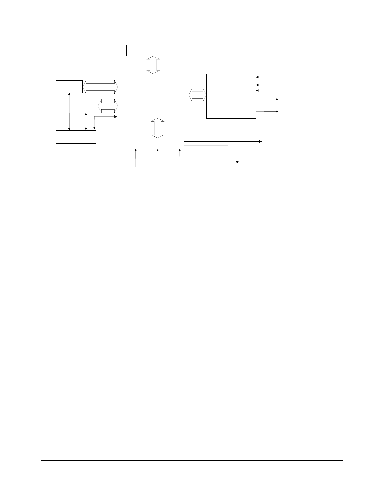
DMA/DPRAM
2ND FIFO
Primary
FIFOS
Interrupts
WATCHDOG TIMER
68331
MICROCOMPUTER
WITH
4 Meg RAM
4 Meg FLASH EEPROM
HIGH-SPEED
MOTOR/ENCODER
INTERFACE
FOR
X,Y,Z,W, etc.
ISOLATED LIMITS AND
HOME INPUTS
MAIN ENCODERS
AUXILIARY ENCODERS
+/- 10 VOLT OUTPUT FOR
SERVO MOTORS
PULSE/DIRECTION OUTPUT
FOR STEP MOTORS
ISA/PCI BUS
I/O INTERFACE
8 UNCOMMITTED
ANALOG INPUTS
HIGH-SPEED LATCH FOR EACH AXIS
8 PROGRAMMABLE,
OPTOISOLATED
8 PROGRAMMABLE
OUTPUTS
INPUTS
HIGH SPEED ENCODER
COMPARE OUTPUT
Figure 1.1 - DMC-1700/1800 Functional Elements
Microcomputer Section
The main processing unit of the controller is a specialized 32-bit Motorola 68331 Series Microcomputer with 512K
byte RAM and 512K byte Flash EEPROM. The RAM provides memory for variables, array elements, and
application programs. The flash EEPROM provides non-volatile storage of variables, programs, and arrays. The
Flash also contains the firmware of the controller, which is field upgradeable.
Motor Interface
Galil’s GL-1800 custom, sub-micron gate array performs quadrature decoding of each encoder at up to 12 MHz.
For standard servo operation, the controller generates a +/-10 Volt analog signal (16 Bit DAC). For sinusoidal
commutation operation, the controller uses 2 DACs to generate 2
operation the controller generates a step and direction signal.
+/-10Volt analog signals. For stepper motor
Communication
The communication interface with the host PC contains a primary and secondary communication channel. The
primary channel uses a bi-directional FIFO and includes PC interrupt handling circuitry. The secondary channel can
be set as DMA or DPRAM where data is placed in PC memory or as a Polling FIFO where data is placed into the
controller’s FIFO buffer. The DMA is available on the DMC-1700 and, DPRAM is only available on the DMC1800 (1810-1840 Rev H and greater, DMC-1850-1880 Rev E and greater), whereas the Polling FIFO is available on
both the DMC-1700 and DMC-1800.
General I/O
The controller provides interface circuitry for 8 bi-directional, optoisolated inputs, 8 TTL outputs, and 8 analog
inputs with 12-Bit ADC (16-bit optional). The general inputs can also be used for triggering a high-speed positional
latch for each axis.
Each axis on the controller has 2 encoders, the main encoder and an auxiliary encoder. Each unused auxiliary
encoder provides 2 additional inputs available for general use (except when configured for stepper motor operation).
DMC-1700/1800 Chapter 1 Overview • 3
Page 12
17X8
1X80
The DMC-1718, 1728, 1738, 1748 controllers have 64 additional general I/O points. The user can
configure these I/O points as inputs or outputs in blocks of 8.
The DMC-1750 through DMC-1780 and DMC-1850 through DMC-1880 controllers provide interface
circuitry for 16 optoisolated inputs, 8 TTL inputs, 16 TTL outputs, and 8 analog inputs with 12-bit
ADC (16-bit optional).
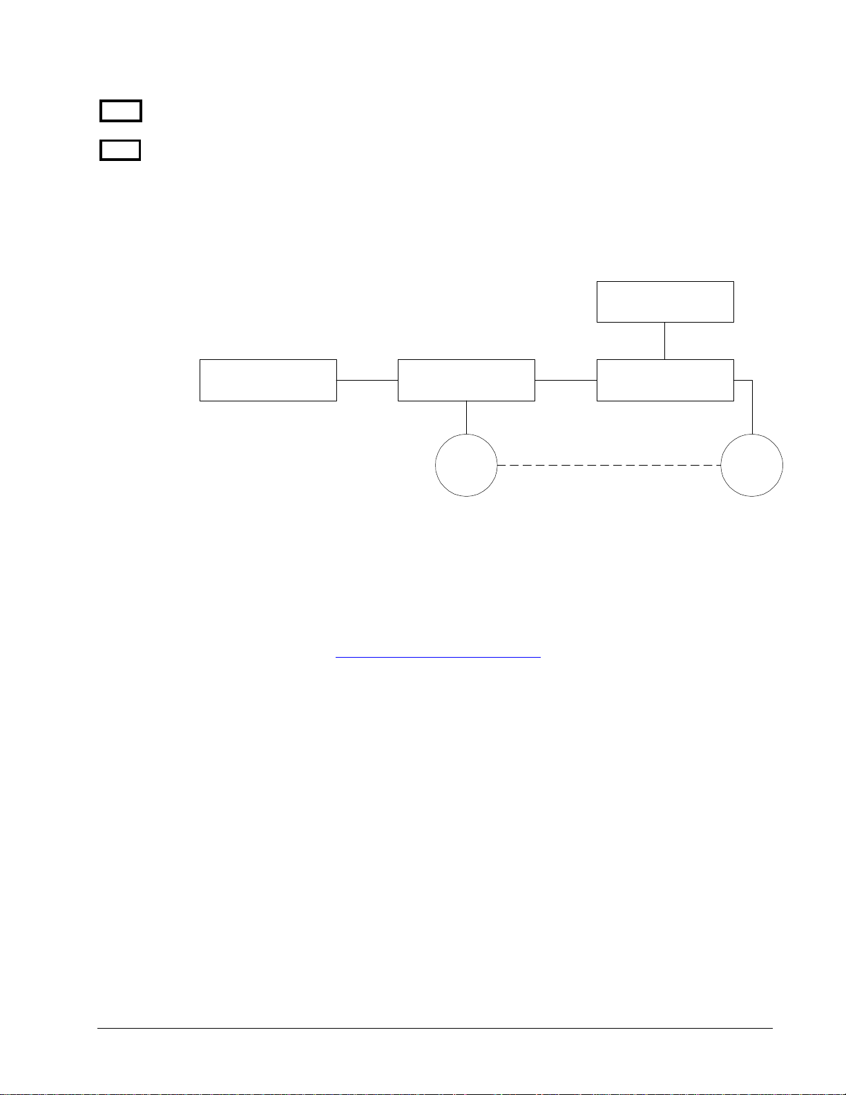
System Elements
As shown in Fig. 1.2, the DMC-1700/1800 is part of a motion control system which includes amplifiers, motors, and
encoders. These elements are described below.
Power Supply
Computer
Figure 1.2 - Elements of Servo systems
DMC-1700/1800
Controller
Encoder Motor
Driver
Motor
A motor converts current into torque, which produces motion. Each axis of motion requires a motor sized properly
to move the load at the required speed and acceleration. (Galil’s “Motion Component Selector” software can help
you with motor sizing). Download at
The motor may be a step or servo motor and can be brush-type or brushless, rotary or linear. For step motors, the
controller can operate full-step, half-step, or microstep drives. An encoder is not required when step motors are
used.
www.galilmc.com/support/download, select “MCS”.
Amplifier (Driver)
For each axis, the power amplifier converts a +/-10 Volt signal from the controller into current to drive the motor.
For stepper motors, the amplifier converts step and direction signals into current. The amplifier should be sized
properly to meet the power requirements of the motor. For brushless motors, an amplifier that provides electronic
commutation is required or the controller must be configured to provide sinusoidal commutation. The amplifiers
may be either pulse-width-modulated (PWM) or linear. They may also be configured for operation with or without
a tachometer. For current amplifiers, the amplifier gain should be set such that a 10 Volt command generates the
maximum required current. For example, if the motor peak current is 10A, the amplifier gain should be 1 A/V. For
velocity mode amplifiers, 10 Volts should run the motor at the maximum speed.
Encoder
An encoder translates motion into electrical pulses which are fed back into the controller. The DMC-1700/1800
accepts feedback from either a rotary or linear encoder. Typical encoders provide two channels in quadrature,
known as CHA and CHB. This type of encoder is known as a quadrature encoder. Quadrature encoders may be
4 • Chapter 1 Overview DMC-1700/1800
Page 13

either single-ended (CHA and CHB) or differential (CHA, CHA-, CHB, CHB-). The controller decodes either type
into quadrature states or four times the number of cycles. Encoders may also have a third channel (or index) for
synchronization.
The DMC-1700/1800 can also interface to encoders with pulse and direction signals. Refer to the “CE” command in
the command reference for details.
There is no limit on encoder line density; however, the input frequency to the controller must not exceed 3,000,000
full encoder cycles/second (12,000,000 quadrature counts/sec). For example, if the encoder line density is 10,000
cycles per inch, the maximum speed is 300 inches/second. If higher encoder frequency is required, please consult
the factory.
The standard encoder voltage level is TTL (0-5v), however, voltage levels up to 12 Volts are acceptable. (If using
differential signals, 12 Volts can be input directly to the DMC-1700/1800. Single-ended 12 Volt signals require a
bias voltage input to the complementary inputs).
The DMC-1700/1800 can accept analog feedback (+/-10v) instead of an encoder for any axis. For more information
see the command AF in the command reference.
To interface with other types of position sensors such as absolute encoders, Galil can customize the controller and
command set. Please contact Galil to talk to one of our applications engineers about your particular system
requirements.
Watch Dog Timer
The DMC-1700/1800 provides an internal watchdog timer which checks for proper microprocessor operation. The
timer toggles the Amplifier Enable Output (AEN), which can be used to switch the amplifiers off in the event of a
serious controller failure. The AEN output is normally high. During power-up and if the microprocessor ceases to
function properly, the AEN output will go low. The error light for each axis will also turn on at this stage. A reset
is required to restore the controller to normal operation. Consult the factory for a Return Materials Authorization
(RMA) Number if your DMC-1700/1800 is damaged.
DMC-1700/1800 Chapter 1 Overview • 5
Page 14

THIS PAGE LEFT BLANK INTENTIONALLY
6 • Chapter 1 Overview DMC-1700/1800
Page 15
Chapter 2 Getting Started
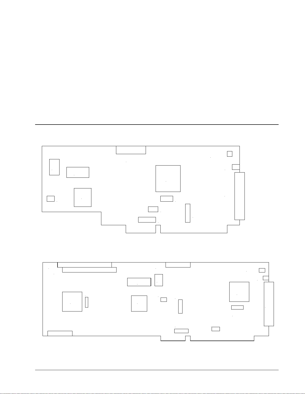
The DMC-17x0 and DMC-18x0 Motion Controllers
J5
JP3
1
5
2
4
J1
JP1
3
JP5
JP4
JP8
JP9
Figure 2-1 - Outline of the DMC-1710 through DMC-1740
J6
J8
4
2
JP4
3
J5
1
JP1
JP3
5
4
JP8
J1
JP5
JP9
J7
Figure 2-2 - Outline of the DMC-1750 through DMC-1780
DMC-1700/1800 Chapter 2 Getting Started • 7
JP6
Page 16
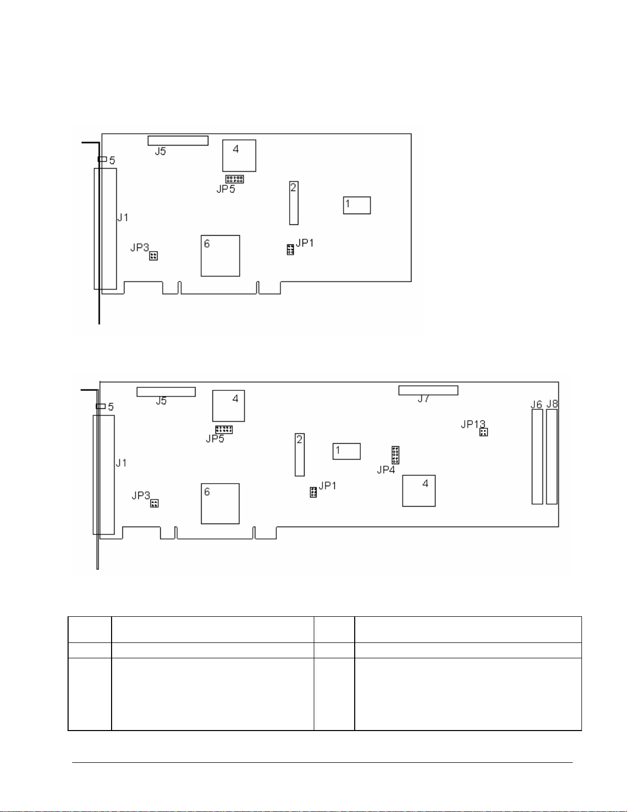
Figure 2-3 - Outline of the DMC-1810 through DMC-1840
Figure 2-4 - Outline of the DMC-1850 through DMC-1880
1 Flash EEPROM J8
2 RAM JP1 Master Reset & UPGRD jumpers
3 Motorola 68331 microprocessor JP3
8 • Chapter 2 Getting Started DMC-1700/1800
50-pin header connector corresponding to pins 1
through 50 of connector for axes 5-8
INCOM & LSCOM jumpers. Used for bypassing optoisolation for the limit, home, and abort switches and the
digital inputs IN1 - IN8. See section “Bypassing OptoIsolation”, Chap3.
DMC-1850/1880 – 1 thru 4 axis only
Page 17

4 Galil GL-1800 custom gate array JP4
5 Error LED JP5
6 Xilinx for PCI bus communications JP6
J1 100-pin high density connector for axes 1-4.
(Part number Amp #2-178238-9)
J5
J6 / J8
J7
26-pin header connector for the auxiliary encoder
cable. (Axes 1-4)
Two 50-pin headers connecting corresponding
signals for axes 5-8
26-pin header connector for the auxiliary encoder
cable. (Axes 5-8)
JP8 Address jumpers A2 – A8
JP9 IRQ jumper.
JP13
Jumpers used for configuring stepper motor operation
on axes 5-8 (DMC-1750/1780 and DMC-1850/1880
only).
Jumpers used to select DMA channel 0 or 1 (DMC1710/1740 only).
Jumpers used for configuring stepper motor operation
on axes 1-4.
Jumpers used to select DMA channel 0 or 1 (DMC1780 only).
INCOM & LSCOM jumpers. Used for bypassing optoisolation for the limit, home, and abort switches and the
digital inputs IN9 – IN16. See section “Bypassing
Opto-Isolation”, Chap3. (DMC-1850/1880 only)
Note: Above layouts are for the most current controller revisions. For older revision boards, please
refer to Appendix.
Elements You Need
Before you start, you must get all the necessary system elements. These include:
1a. DMC-1710/1810, 1720/1820, 1730/1830, or DMC-1740/1840 Motion Controller, (1)
100-pin cable, and (1) ICM-1900 interconnect module.
or
1b. DMC-1750/1850, 1760/1860, 1770/1870 or DMC-1780/1880, (2) 100-pin cables and (2)
ICM-1900s. CB 50-100 connector board and included two 50-pin ribbon cables which
converts the two 50-pin ribbon cables into a single 100-pin connector.
or
1c. DMC-1718, 1728, 1738, 1748, (1) 100-pin cables and (1) ICM-1900s. Connection to the
extended I/O can be made through the IOM-1964 opto-isolation module. Using the IOM1964 requires (1) IOM-1964, (1) CB-50-100 and (1) 100 pin cable.
2. Servo motors with Optical Encoder (one per axis) or step motors.
3. Power Amplifiers.
4. Power Supply for Amplifiers.
5. PC (Personal Computer - ISA bus or PCI bus).
6. Galil SmartTerm (from CD ROM or download at www.galilmc.com)
7. WSDK is optional but recommended for first time users.
The motors may be servo (brush type or brushless) or steppers. The amplifiers should be suitable for the motor and
may be linear or pulse-width-modulated. An amplifier may have current feedback, voltage feedback or velocity
feedback
.
DMC-1700/1800 Chapter 2 Getting Started • 9
Page 18

For servo motors in current mode, the amplifiers should accept an analog signal in the +/-10 Volt range
as a command. The amplifier gain should be set such that a +10V command will generate the
maximum required current. For example, if the motor peak current is 10A, the amplifier gain should
be 1 A/V. For velocity mode amplifiers, a command signal of 10 Volts should run the motor at the
maximum required speed. Set the velocity gain so that an input signal of 10V, runs the motor at the
maximum required speed.
The WSDK software is highly recommended for first time users of the DMC-1700/1800. It provides step-by-step
instructions for system connection, tuning and analysis.
For step motors, the amplifiers should accept step and direction signals. For start-up of a step motor
system refer to Step 8c “Connecting Step Motors”.
Installing the DMC-1700/1800
Installation of a complete, operational DMC-1700/1800 system consists of 9 steps.
Step 1. Determine overall motor configuration.
Step 2. Install Jumpers on the DMC-1700/1800.
Step 3. Install the communications software.
Step 4. Install the DMC-1700/1800 in the PC.
Step 5. Establish communications with the Galil Communication Software.
Step 6. Determine the Axes to be used for sinusoidal commutation.
Step 7. Make connections to amplifier and encoder.
Step 8a. Connect standard servo motors.
Step 8b. Connect sinusoidal commutation motors
Step 8c. Connect step motors.
Step 9. Tune the servo system
Step 1. Determine Overall Motor Configuration
Before setting up the motion control system, the user must determine the desired motor configuration. The DMC1700/1800 can control any combination of standard servo motors, sinusoidally commutated brushless motors, and
stepper motors. Other types of actuators, such as hydraulics can also be controlled, please consult Galil.
The following configuration information is necessary to determine the proper motor configuration:
Standard Servo Motor Operation:
The DMC-1700/1800 has been setup by the factory for standard servo motor operation providing an analog
command signal of +/- 10V. No hardware or software configuration is required for standard servo motor operation.
Sinusoidal Commutation:
Sinusoidal commutation is configured through a single software command, BA. This configuration causes the
controller to reconfigure the number of available control axes.
Each sinusoidally commutated motor requires two DAC’s. In standard servo operation, the DMC-1700/1800 has
one DAC per axis. In order to have the additional DAC for sinusoidal commutation, the controller must be
designated as having one additional axis for each sinusoidal commutation axis. For example, to control two
10 • Chapter 2 Getting Started DMC-1700/1800
Page 19

standard servo axes and one axis of sinusoidal commutation, the controller will require a total of four DAC’s and the
controller must be a DMC-1740 or DMC-1840.
Sinusoidal commutation is configured with the command, BA. For example, BAX sets the X axis to be sinusoidally
commutated. The second DAC for the sinusoidal signal will be the highest available DAC on the controller. For
example: Using a DMC-1740, the command BAX will configure the X axis to be the main sinusoidal signal and the
‘W’ axis to be the second sinusoidal signal.
The BA command also reconfigures the controller to indicate that the controller has one less axis of ‘standard’
control for each axis of sinusoidal commutation. For example, if the command BAX is given to a DMC-1740
controller, the controller will be re-configured to a DMC-1730 controller. By definition, a DMC-1730 controls 3
axes: X,Y and Z. The ‘W’ axis is no longer available since the output DAC is being used for sinusoidal
commutation.
Further instruction for sinusoidal commutation connections are discussed in Step 6.
Stepper Motor Operation:
To configure the DMC-1700/1800 for stepper motor operation, the controller requires a jumper for each stepper
motor and the command, MT, must be given. The installation of the stepper motor jumper is discussed in the
following section entitled “Installing Jumpers on the DMC-1700/1800”. Further instruction for stepper motor
connections are discussed in Step 8c.
Step 2. Install Jumpers on the DMC-1700/1800
Master Reset and Upgrade Jumpers
JP1 contains two jumpers, MRST and UPGRD. The MRST jumper is the Master Reset jumper. With
MRST connected, the controller will perform a master reset upon PC power up or upon the reset input
going low. Whenever the controller has a master reset, all programs, arrays, variables, and motion
control parameters stored in EEPROM will be ERASED.
The UPGRD jumper enables the user to unconditionally update the controller’s firmware. This jumper
is not necessary for firmware updates when the controller is operating normally, but may be necessary
in cases of corrupted EEPROM. EEPROM corruption should never occur, however, it is possible if
there is a power fault during a firmware update. If EEPROM corruption occurs, your controller may
not operate properly. In this case, install the UPGRD Jumper and use the update firmware function on
the Galil Terminal to re-load the system firmware.
Opto Isolation Jumpers
The inputs and limit switches are optoisolated. If you are not using an isolated supply, the internal
+5V supply from the PC may be used to power the optoisolators. This is done by installing jumpers on
JP3 and/or JP13.
For each axis that will be used for stepper motor operation, the corresponding stepper mode (SM)
jumper must be connected. The stepper motor jumpers, labeled JP5 for axes X through W and JP4 for
axes E through H, are located directly beside the GL-1800 IC’s on the main board (see the diagram for
the DMC-1700/1800). The individual jumpers are labeled SMX, SMY, SMZ and SMW for axes 1
through 4 and SME, SMF, SMG and SMH for axes 5 through 8.
Stepper Motor Jumpers
(Optional) DMA Jumpers
The DMA channel is only available with the DMC-1700 controller. The DMC-1700 controller allows
either DMA channel 0 or 1 to be selected. The jumper location JP4 on the DMC-1740 and JP6 on the
DMC-1700/1800 Chapter 2 Getting Started • 11
Page 20

DMC-1780 allows the user to select which channel will be used. The DMA channel chosen should be
Q
K
Q
K
reflected within the Galil software registry. 2.5 illustrates these settings.
Please note earlier controller revisions (Rev. E and earlier for DMC-1740, Rev. C and earlier for
DMC-1780) did not have hardware jumpers for DMA channel selection.
0
DR
1
DAC
Setting for DMA channel 1 Setting for DMA channel 0
Figure 2.5 - Jumper settings for DMC-1700 DMA
DR
DAC
(Optional) IRQ (Interrupt) Jumpers
IRQ jumpers are not necessary for communication with the Galil controllers. Rather, they are an
option that may be used for notifying the PC of events that occur on the motion controller. The
selectable IRQ jumpers are only available on the DMC-1700. The PCI drivers for the DMC-1800 will
automatically assign it an IRQ based on system availability.
On the DMC-1700, select which IRQ line will be used when the controller needs to notify the PC of an
interrupt. You will need to select an IRQ line which is open on your PC, meaning not shared with any
other device. Within the Galil Software Registry, the corresponding IRQ line should be entered into
the controller registry information.
NOTE: For Version 7 Drivers and ISA/PC-104 controllers with new firmware, a jumper MUST
be installed on one of the IRQ jumper pins in order to use Interrupt Communicati on (the default
method of communication). Match the IRQ jumper on the board with an IRQ Setting that
displays “No Conflicts” in the Device Manager.
1 0
If No IRQ lines are available or Interrupt Communication is not desired, the user must go to the
“Controller Registration” menu and uncheck the “Interrupt Communication” method. Stall or
Delay methods of communication will then be used. A Communication Timeout error will occur
if this is not done.
(Optional) Motor Off Jumpers
The state of the motor upon power up may be selected with the placement of a hardware jumper on the
controller. With a jumper installed at the MO location, the controller will be powered up in the ‘motor
off’ state. The SH command will need to be issued in order for the motor to be enabled. With no
jumper installed, the controller will immediately enable the motor upon power up. The MO command
will need to be issued to turn the motor off.
The MO jumper is always located on the same block of jumpers as the stepper motor jumpers (SM).
This feature is only available to newer revision controllers (Rev. F and later for DMC-1740, Rev. D
and later for DMC-1780, Rev. C and later for DMC-1840). Please consult Galil for adding this
functionality to older revision controllers.
12 • Chapter 2 Getting Started DMC-1700/1800
Page 21

Configuring the Address Jumpers on the DMC-1700
The DMC-1700 address, N, is selectable by setting the address jumpers labeled A2, A3, A4, A5, A6,
A7 and A8 where each jumper represents a digit of the binary number that is equivalent to N minus
512. Jumper A2 represents the 2
digit (the 4th binary digit from the right) and so on up to the most significant digit, which is represented
by jumper A8. The 2 least significant (rightmost) digits are not represented. A location with a jumper
placed on the board means the value of the digit represented by that jumper is 0. If the jumper is open,
the digit is 1.
Because the least significant digit represented by the Address Jumpers is the 2
addresses divisible by 4 are configurable on the DMC-1700. The DMC-1700 can be configured for
th
address between 512 and 1024. To configure an address you must do the following:
any 4
1. Select an address, N, between 512 and 1024, divisible by 4. Example: 516
2. Subtract 512 from N. Example: 516 – 512 = 4
3. Convert the resultant number into a 9-digit binary number being sure to represent all
leading zeros. Using our example: Converting 4 to binary results in 100. As a 9-digit
binary number, this is represented by 000000100.
4. Truncate the 2 least significant (rightmost) digits. Example: 0000001.
5. Set the jumpers as described above. Again, jumper at the location is represented by a 0,
while no jumper at the location represents a 1.
To simplify this task, there is a complete list of jumper settings for the DMC-1700 found in the
appendix in the section Setting Addresses for the DMC-1700.
2
digit (the 3rd binary digit from the right), jumper A3 represents the 2
2
digit (jumper A2), only
3
Step 3. Install the Communications Software
Before installing the controller in the PC, Galil communications software terminal and drivers should
be loaded. Installing the Galil software prior to installing the card will allow most operating system to
automatically install the DMC-1800 (PCI) controller into both the Windows and Galil registries.
Install the Galil Software Products CD-ROM into your CD drive. A Galil .htm page should
automatically appear with links to the software products. Select “DMCSmartTerm” and click
“Install…” Follow the installation procedure as outlined.
Using the Galil Software CD-ROM, go to the directory, D:\July2000 CD\DMCDOS\Disk1. Type
"INSTALL" at the DOS prompt and follow the directions.
Using the Galil Software CD ROM, go to the directory, D:\July2000 CD\DMCWIN. Select
DMCWIN16.exe and follow the directions.
Using Win98SE, ME, NT4.0, 2000, and XP
Using DOS:
Using Windows 3.x (16 bit versions):
Using Windows 95, 98(first edition):
Using the Galil Software CD ROM, go to the directory, D:\July2000 CD\DMCWIN. Select
DMCWIN32.exe and follow the directions.
DMC-1700/1800 Chapter 2 Getting Started • 13
Page 22

1X80
Note: Galil software is also available for download at: http://www.galilmc.com/support/download.html
Step 4. Install the DMC-1700/1800 in the PC
The DMC-1700 is installed directly into the ISA expansion bus. The DMC-1800 is installed directly
into the PCI expansion bus. The procedures are outlined below.
Step A. Make sure the PC is in the power-off condition.
Step B. Remove unit cover.
Step C. Remove the metal plate covering the expansion bus slot where the DMC-1700/1800
will be inserted.
Step D. Insert DMC-1700/1800 card in the expansion bus and secure with screw.
Step E. Attach 100-pin cable to your controller card. If you are using a Galil ICM-1900 or
AMP-19X0, this cable connects into the J2 connection on the interconnect module. If
you are not using a Galil interconnect module, you will need to appropriately terminate
the cable to your system components, see the appendix for cable pin outs. The auxiliary
encoder connections are accessed through the 26-pin IDC connector, J5.
If you are using a controller with more than 4 axes you will need a CB-50-100 converter board, which
brings out a second 100-pin cable to be attached to the second ICM-1900. Two 50-pin ribbon cables
attach the CB-50-100 to the DMC-1780.
DMC-1700 Install:
The DMC-1700 is addressed manually, with a default address of 1000. Earlier controller revisions
(Rev. E and earlier for DMC-1740, Rev. C and earlier for DMC-1780) had Plug-and-Play utilities,
which have been removed on the most current revisions. Please refer to the appendix if your controller
has the Plug-and-Play functionality. If an address other than 1000 is necessary for your controller,
refer to Step-2.
DMC-1800 Install:
The installation of the DMC-1800 will vary with operating systems due to how the PCI is handled
within that operating system. For Win98SE, ME, NT4.0, 2000 and XP, the OS will automatically
install the drivers. With Windows 95 or 98, upon power up your computer should recognize the DMC1800 as a new device and will prompt you for an “Installation Disk”. The computer will ask you to
point towards the DMC1800.INF file on your PC. This file will automatically configure the controller
for your computer’s available resources. The installation will also automatically add this information
to the Galil Registry (see Step 5 below).
Step 5. Establishing Communication between the Galil controller and the host PC
Using Galil Software for DOS (DMC-1700 only)
To communicate with the DMC-1700, type DMCTERM at the prompt. You will need to provide
information about your controller such as controller type (DMC-1700), address, and IRQ. Once you
have established communication, the terminal display should show a colon “:”. If you do not receive a
colon, press the carriage return.
If you still do not receive a colon, the most likely cause is an address conflict in your computer. If the
default of address 1000 causes a conflict, Galil recommends the addresses of 816 and 824, since they
are likely to avoid conflict. Please refer to Step-2 Configuring the Address Jumpers on the DMC-1700
to change the address.
14 • Chapter 2 Getting Started DMC-1700/1800
Page 23

Using Galil Software for Windows 3.x, 95 and 98 First Edition (DMC-1700
only)
In order for the Windows software to communicate with a Galil controller, the controller must be
registered in the Windows Registry. To register a controller, you must specify the model of the
controller, the communication parameters, and other information. The registry is accessed through the
Galil software, such as WSDK and DTERM (DTERM is installed with DMCWIN and installed as the
icon “Galil Terminal”). From WSDK, the registry is accessed under the FILE menu. From the
DTERM program, the registry is accessed from the REGISTRY menu.
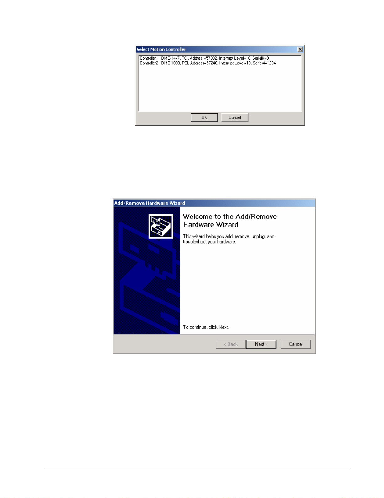
The registry window is equipped with buttons to Add, Change, or Delete a controller. Pressing any of
these buttons will bring up the Set Registry Information window.
Use the Add button to add a new entry to the Registry. You will need to supply the Galil Controller
type. The controller model number must be entered and if you are changing an existing controller, this
field will already have an entry. Pressing the down arrow to the right of this field will reveal a menu of
valid controller types. Choose the corresponding controller (DMC-1700).
The registry information for the DMC-1700 will show a default address of 1000. This information
should be changed as necessary to reflect any changes to the controllers address jumpers. Hardware
interrupts may also be set in the registry, although for initial communication these are not necessary.
The default is no interrupt. Driver information is also listed, in which Galil recommends using the
standard Galil Drivers.
The registry entry also displays timeout and delay information. These are advanced parameters that
should only be modified by advanced users (see software documentation for more information).
Once you have set the appropriate Registry information for your controller, Select OK and close the
registry window. You will now be able to communicate with the DMC-1700. Once the entry has been
selected, click on the OK button. If the software has successfully established communications with the
controller, the registry entry will be displayed at the top of the screen.
If you are not properly communicating with the controller, the program will pause for 3-15 seconds.
The top of the screen will display the message “Status: not connected with Galil motion controller” and
the following error will appear: “STOP - Unable to establish communication with the Galil controller.
A time-out occurred while waiting for a response from the Galil controller.” If this message appears,
you must click OK. In this case, there is most likely an address conflict.
If you receive this error, the most likely cause is an address conflict in your computer. If the default of
address 1000 causes a conflict, Galil recommends the addresses of 816 and 824, since they are likely to
avoid conflict. Please refer to Step-2 Configuring the Address Jumpers on the DMC-1700 to change
the address.
Once you establish communications, click on the menu for terminal and you will receive a colon
prompt. Communicating with the controller is described in later sections.
Using Galil Software for Windows 98 SE, ME, XP, and 2000
In order for the Windows software to communicate with a Galil controller, the controller must be
entered in the Windows Registry. In Windows 98 SE, 2000 and XP operating systems (OS), the
DMC-1800 is plug and play. This means that on power up the computer will automatically detect the
card and install the appropriate device driver. A ‘Found New Hardware’ dialog box may appear
during installation of the device driver. The controller will be identified by model name and entered
into the Galil Registry. Now the user can communicate to the controller using DMCSmartTERM.
Note: In order for the PC to recognize the plug and play controller as a Galil device, the Galil
software must be loaded prior to installing the card.
DMC-1700/1800 Chapter 2 Getting Started • 15
Page 24
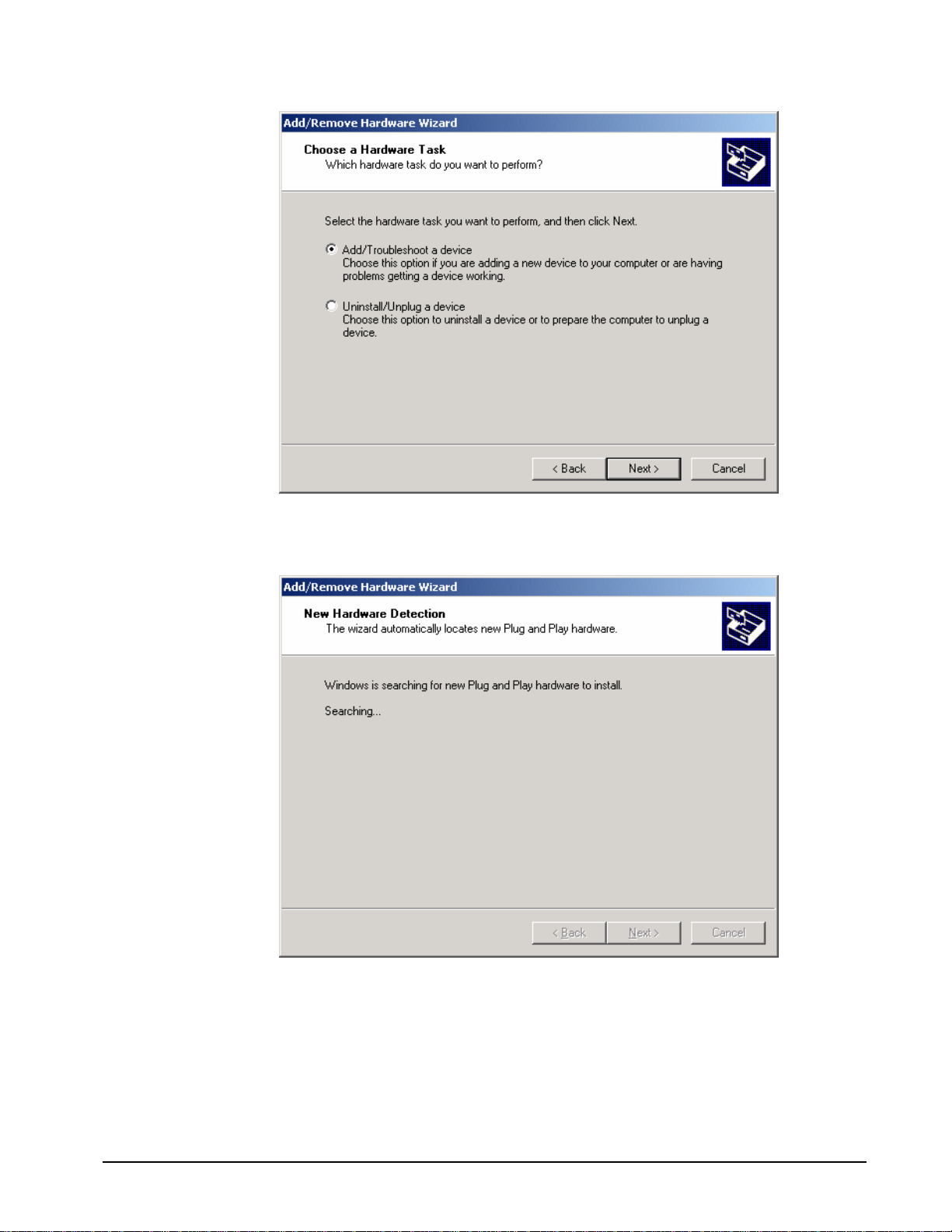
DMC-1800 and DMC-1417 in the Galil Registry
Using a DMC-1700 card in a plug and play OS (Win 98 SE, 2000, ME, XP) will require adding the
controller to the system in the Windows Device Manager. In Win 98 SE and ME this feature is
accessed through the Start\Settings\Control Panel\Add New Hardware shortcut. In Win 2000 and XP
it can be accessed through My Computer\Properties\Hardware\Hardware Wizard. The procedures on
the two operating systems are nearly identical, but the dialog boxes may look a little different.
Windows 2000 Hardware Wizard
Note: All the pictures in this Hardware Wizard section are from Windows 2000 unless specified
otherwise.
1. On the first dialog, select Add/Troubleshoot
16 • Chapter 2 Getting Started DMC-1700/1800
Page 25
Let the Hardware Wizard try to detect a new Plug and Play device.
2.
3. If a device is found, the Hardware Wizard will then ask if the device is on a list of found
devices. Say no and proceed to the next dialog box. In Win 2000, the next window will
display a list of devices. Select “Add a new device” from the top of the list.
DMC-1700/1800 Chapter 2 Getting Started • 17
Page 26
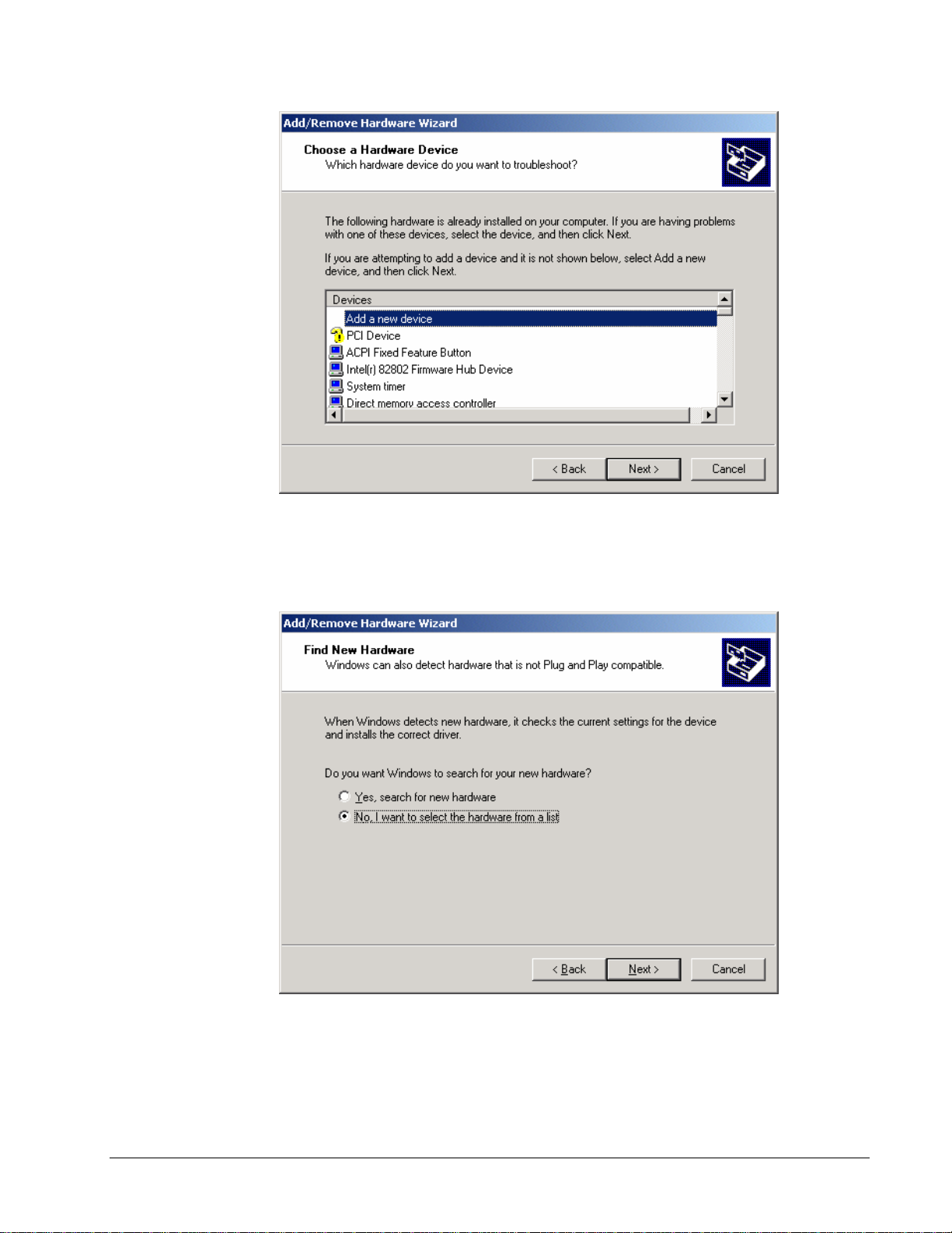
4. The Hardware Wizard prompts for Windows to search for the new device. This feature is for
devices such as modems that can be found by ‘random’ queries of all available
communication ports. Select, ‘No’ and proceed to the next dialog.
With DMCWIN32 or DMCTERM already installed, the following window will say, “Select
5.
the type of hardware you want to install”. Click on the Diamond with either “Galil” or “Galil
Motion Control” written to the side of it, and the list of Galil controllers will be displayed.
Select the DMC-1700 card from the list.
18 • Chapter 2 Getting Started DMC-1700/1800
Page 27
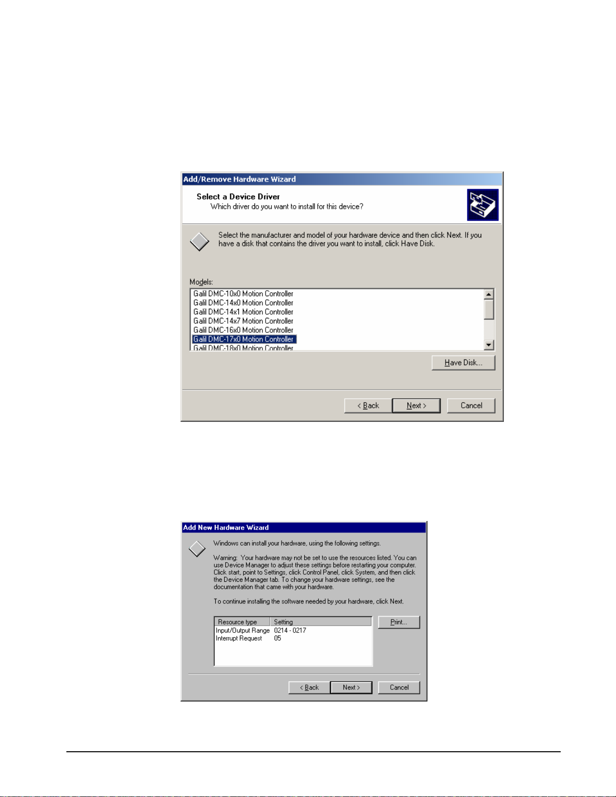
Note: If this is the first time a 1700 card has been installed on the machine, then the Galil
diamond may not be present. If there is no Galil diamond on the Hardware Type window,
click on Other Devices instead. At that point, the list of Galil ISA and PC/104 cards will
appear.
6. With the device selected, the OS then needs to allocate any required resources.
6a. In Win 98 SE and ME the OS automatically assigns resources that are most likely
incompatible.
Automatically Assigned resources in Win 98 SE
DMC-1700/1800 Chapter 2 Getting Started • 19
Page 28
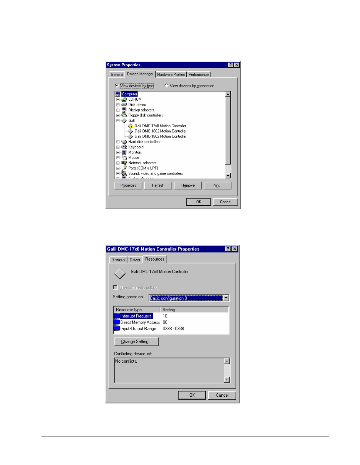
At this point the user must reboot and go to the Device Manager under My Computer\Properties.
Device Manager in Win 98 SE
Select the device from the list, go to the resource tab, and reassign the resources to those that match the
address and interrupt (IRQ) jumpers on the controller (see the appendix for ‘Address Settings’ and
Step 3 for installing jumpers).
Changing the Resources in Win 98 SE
20 • Chapter 2 Getting Started DMC-1700/1800
Page 29
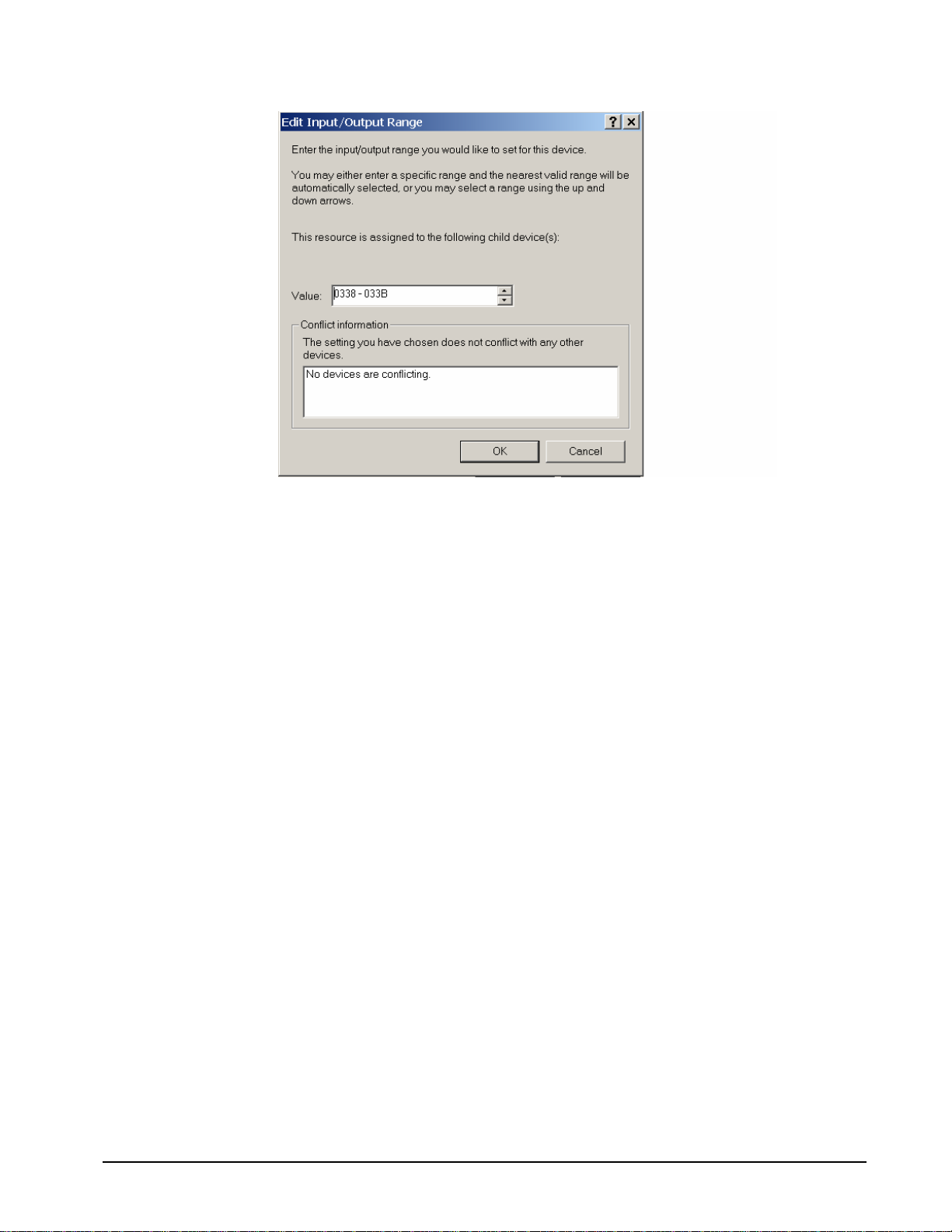
Edit Input/Output Range in Win 98 SE
When changing the settings, the operating system will inform the user of any resource conflicts. If
there are resource conflicts, it is necessary to compare the available resources to those on the jumpers,
and select a configuration that is compatible. If all configurations have a resource conflict, then the
user will have to reconfigure or remove another card to free up some resources. This is most likely to
happen with IRQs, as they can be scarce.
Note: The “Input/Output Range” is used to assign a communication address to the controller. This
address is given in hexadecimal, which means the user should use the scientific calculator in
Start\Programs\Accessories to convert the decimal address desired into its hexadecimal equivalent.
The user can just enter a single hexidecimal number into the ‘Value:’ box and the OS will assign an
I/O range to it.
6b. In Win 2000, the procedure is the same except the user has the opportunity to set
resources/examine conflicts without rebooting first. Highlight the “Interrupt Request” and
“Input/Output Range” individually and select ‘Change Setting…’ to make the appropriate adjustments.
Similar to Windows 98, the “Input/Output Range” must be assigned as a hexadecimal number.
DMC-1700/1800 Chapter 2 Getting Started • 21
Page 30
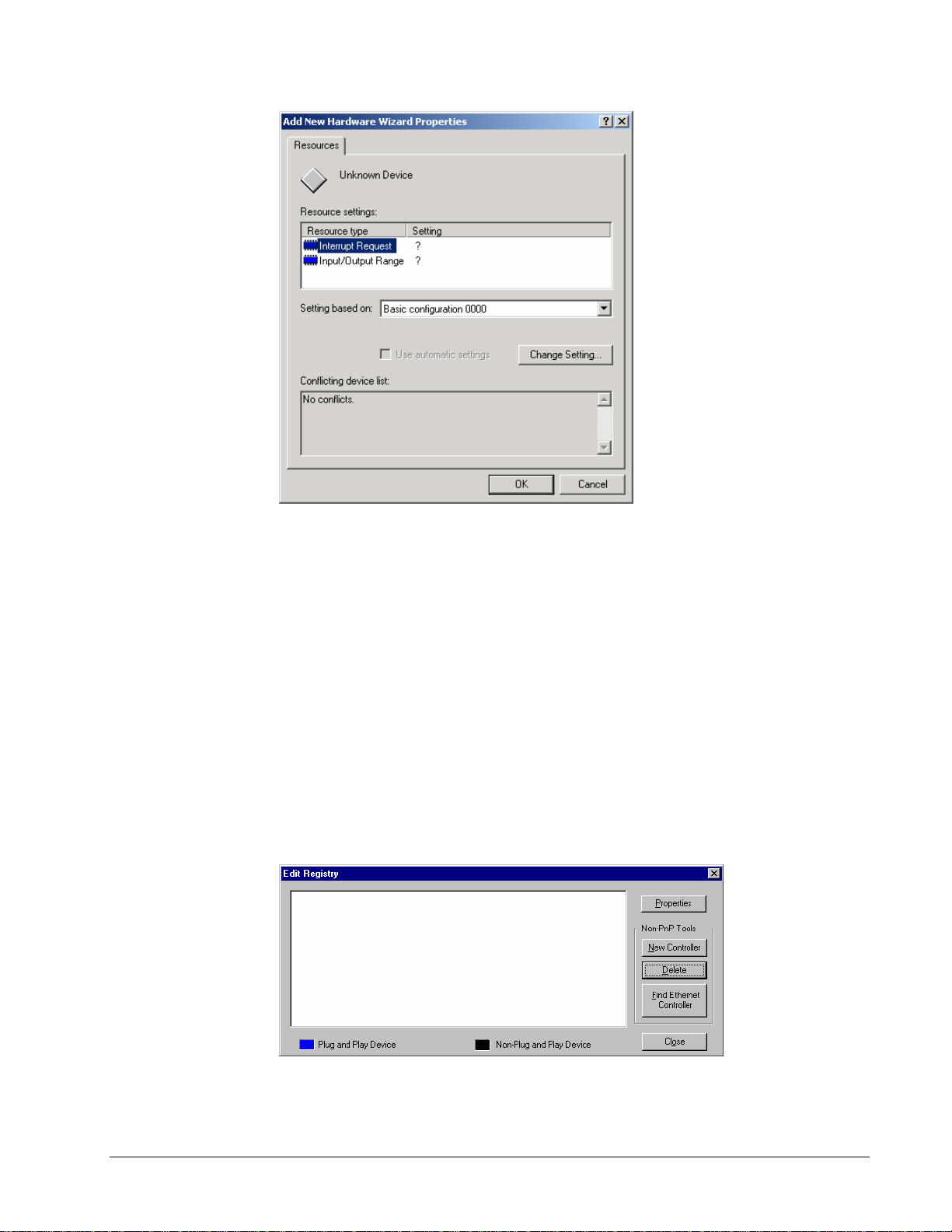
7. Once the controller is properly entered into the Windows registry, it should also be present in
the Galil Registry. The address and IRQ jumpers on the controller may need to be changed depending
on the resources available in Windows (see Step 3 for setting address and IRQ jumpers). Connect to
the controller through the Terminal utility in DMCWIN32, WSDK32, or DMCTERM.
Using Galil Software for Windows NT 4
In Windows NT 4, the DMC-1800 is also plug and play. This means that on power up the computer
will automatically detect the card and install the appropriate device driver. A ‘Found New Hardware’
dialog box may appear during installation of the device driver. The controller will be identified by
model name and entered into the Galil Registry. Now the user can communicate to the controller using
DMCTERM, DMCWIN32, or WSDK32.
To use a DMC-1700 in Win NT4, add the controller using the Galil Registry dialog. To access the
registry in DMCTERM and WSDK, click on the File menu and “Register Controller”. In
DMCWIN32, select the Registry menu.
22 • Chapter 2 Getting Started DMC-1700/1800
Page 31

Once in the Galil Registry, click New Controller under Non-PnP Tools. Select the appropriate
controller from the pull down menu and adjust the timeout as seen fit. Click Next to continue.
The registry information for the DMC-1700 card will show a default address of 1000. This
information should be changed as necessary to reflect any changes to the controller’s address jumpers.
Hardware interrupts may also be set in the registry, although for initial communication these are not
necessary. The default interrupt selection is “None”.
Once the appropriate Registry information has been entered, Select OK and close the registry window.
After rebooting the computer, communication to the DMC-1700 card can be established. Reopen one
of the communication programs and select the controller from the registry list.
DMC-1700/1800 Chapter 2 Getting Started • 23
Page 32

If there are communication problems, the program will pause for 3-15 seconds. The top of the dialog
box will display the message “Status: not connected with Galil motion controller” and the following
error will appear: “STOP - Unable to establish communication with the Galil controller. A time-out
occurred while waiting for a response from the Galil controller.”
If this error occurs in Windows NT 4, the most likely cause is an address conflict in the computer. If
the default of address 1000 causes a conflict, Galil recommends the addresses of 816 and 824, since
they are likely to avoid conflict. Please refer to Step-2 Configuring the Address Jumpers on the DMC-
1700 to change the address. If the address jumpers are changed, the Galil registry must be modified to
reflect these changes.
Once communication is established, click on the menu for terminal and you will receive a colon
prompt. Communicating with the controller is described in later sections.
Sending Test Commands to the Terminal:
After you connect your terminal, press <carriage return> or the <enter> key on your keyboard. In
response to carriage return (CR), the controller responds with a colon “:”.
Now type
TPX (CR)
This command directs the controller to return the current position of the X-axis. The controller should
respond with a number such as
0
Step 6. Determine the Axes to be Used for Sinusoidal Commutation
Note: This step is only required when the controller will be used to control a brushless motor(s) with sinusoidal
commutation. The command, BA is used to select the axes of sinusoidal commutation. For example, BAXZ sets X
and Z as axes with sinusoidal commutation.
Notes on Configuring Sinusoidal Commutation:
The command, BA, reconfigures the controller such that it has one less axis of ‘standard’ control for each axis of
sinusoidal commutation. For example, if the command BAX is given to a DMC-1740 controller, the controller will
be re-configured to be a DMC-1730 controller. In this case the highest axis is no longer available except to be used
for the 2
for sinusoidal commutation.
The first phase signal is the motor command signal. The second phase is derived from the highest DACX on the
controller. When more than one axis is configured for sinusoidal commutation, the highest sinusoidal commutation
axis will be assigned to the highest DAC and the lowest sinusoidal commutation axis will be assigned to the lowest
available DAC. Note the lowest axis is the X axis.
This command causes the controller to be reconfigured as a DMC-1750 controller. The X and Z axes are configured
for sinusoidal commutation. The first phase of the X axis will be the motor command X signal. The second phase
of the X axis will be F signal. The first phase of the Z axis will be the motor command Z signal. The second phase
of the Z axis will be the motor command G signal.
nd
phase of the sinusoidal commutation. Note that the highest axis on a controller can never be configured
Example: Sinusoidal Commutation Configuration using a DMC-1770
BAXZ
24 • Chapter 2 Getting Started DMC-1700/1800
Page 33

Step 7. Make Connections to Amplifier and Encoder.
Once you have established communications between the software and the DMC-1700/1800, you are ready to
connect the rest of the motion control system. The motion control system typically consists of an ICM-1900
Interface Module, an amplifier for each axis of motion, and a motor to transform the current from the amplifier into
torque for motion. Galil also offers the AMP-19X0 series Interface Modules which are ICM-1900’s equipped with
servo amplifiers for brush type DC motors.
If you are using an ICM-1900, connect the 100-pin ribbon cable to the DMC-1700/1800 and to the connector located
on the AMP-19x0 or ICM-1900 board. The ICM-1900 provides screw terminals for access to the connections
described in the following discussion.
1X80
System connection procedures will depend on system components and motor types. Any combination of motor
types can be used with the DMC-1700/1800. If sinusoidal commutation is to be used, special attention must be paid
to the reconfiguration of axes.
Here are the first steps for connecting a motion control system:
WARNING: When the amplifier ground is not isolated from the power line or when it has a different potential
than that of the computer ground, serious damage may result to the computer controller and amplifier.
Motion Controllers with more than 4 axes require a second ICM-1900 or AMP-19x0 and second 100pin cable.
Step A. Connect the motor to the amplifier with no connection to the controller. Consult the
amplifier documentation for instructions regarding proper connections. Connect and
turn-on the amplifier power supply. If the amplifiers are operating properly, the motor
should stand still even when the amplifiers are powered up.
Step B. Connect the amplifier enable signal.
Before making any connections from the amplifier to the controller, you need to verify that
the ground level of the amplifier is either floating or at the same potential as earth.
If you are not sure about the potential of the ground levels, connect the two ground signals
(amplifier ground and earth) by a 10 KΩ resistor and measure the voltage across the
resistor. Only if the voltage is zero, connect the two ground signals directly.
The amplifier enable signal is used by the controller to disable the motor. This signal is
labeled AMPENX for the X axis on the ICM-1900 and should be connected to the enable
signal on the amplifier. Note that many amplifiers designate this signal as the INHIBIT
signal. Use the command, MO, to disable the motor amplifiers - check to insure that the
motor amplifiers have been disabled (often this is indicated by an LED on the amplifier).
This signal changes under the following conditions: the watchdog timer activates, the motor-
off command, MO, is given, or the OE1 command (Enable Off-On-Error) is given and
the position error exceeds the error limit. AEN can be used to disable the amplifier for
these conditions.
The standard configuration of the AEN signal is TTL active high. In other words, the
AEN signal will be high when the controller expects the amplifier to be enabled. The
polarity and the amplitude can be changed if you are using the ICM-1900 interface board.
To change the polarity from active high (5 volts = enable, zero volts = disable) to active
low (zero volts = enable, 5 volts = disable), replace the 7407 IC with a 7406. Note that
many amplifiers designate the enable input as ‘inhibit’.
To change the voltage level of the AEN signal, note the state of the resistor pack on the
ICM-1900. When Pin 1 is on the 5V mark, the output voltage is 0-5V. To change to 12
volts, pull the resistor pack and rotate it so that Pin 1 is on the 12 volt side. If you
remove the resistor pack, the output signal is an open collector, allowing the user to
connect an external supply with voltages up to 24V.
Step C. Connect the encoders
DMC-1700/1800 Chapter 2 Getting Started • 25
Page 34

For stepper motor operation, an encoder is optional.
For servo motor operation, if you have a preferred definition of the forward and reverse
directions, make sure that the encoder wiring is consistent with that definition.
The DMC-1700/1800 accepts single-ended or differential encoder feedback with or without
an index pulse. If you are not using the AMP-19x0 or the ICM-1900 you will need to
consult the appendix for the encoder pinouts for connection to the motion controller. The
AMP-19x0 and the ICM-1900 can accept encoder feedback from a 10-pin ribbon cable or
individual signal leads. For a 10-pin ribbon cable encoder, connect the cable to the
protected header connector labeled X ENCODER (repeat for each axis necessary). For
individual wires, simply match the leads from the encoder you are using to the encoder
feedback inputs on the interconnect board. The signal leads are labeled CHA (channel
A), CHB (channel B), and INDEX. For differential encoders, the complement signals are
labeled CHA-, CHB-, and INDEX-.
Note: When using pulse and direction encoders, the pulse signal is connected to CHA and the
direction signal is connected to CHB. The controller must be configured for pulse and
direction with the command CE. See the command summary for further information on
the command CE.
Step D. Verify proper encoder operation.
Start with the X encoder first. Once it is connected, turn the motor shaft and interrogate the
position with the instruction TPX <return>. The controller response will vary as the
motor is turned.
At this point, if TPX does not vary with encoder rotation, there are three possibilities:
1. The encoder connections are incorrect - check the wiring as necessary.
2. The encoder has failed - using an oscilloscope, observe the encoder signals. Verify
that both channels A and B have a peak magnitude between 5 and 12 volts. Note
that if only one encoder channel fails, the position reporting varies by one count
only. If the encoder failed, replace the encoder. If you cannot observe the encoder
signals, try a different encoder.
3. There is a hardware failure in the controller - connect the same encoder to a different
axis. If the problem disappears, you probably have a hardware failure. Consult the
factory for help.
Step E. Connect Hall Sensors if available.
Hall sensors are only used with sinusoidal commutation and are not necessary for proper
operation. The use of hall sensors allows the controller to automatically estimate the
commutation phase upon reset and also provides the controller the ability to set a more
precise commutation phase. Without hall sensors, the commutation phase must be
determined manually.
The hall effect sensors are connected to the digital inputs of the controller. These inputs can
be used with the general use inputs (bits 1-8), the auxiliary encoder inputs (bits 81-96), or
the extended I/O inputs of the DMC-17x8 controller (bits 17-80). Note: The general use
inputs are optoisolated and require a voltage connection at the INCOM point - for more
information regarding the digital inputs, see Chapter 3, Connecting Hardware.
Each set of sensors must use inputs that are in consecutive order. The input lines are specified
with the command, BI. For example, if the Hall sensors of the Z axis are connected to
inputs 6, 7 and 8, use the instruction:
BI ,, 6
or
BIZ = 6
26 • Chapter 2 Getting Started DMC-1700/1800
Page 35

Step 8a. Connect Standard Servo Motors
The following discussion applies to connecting the DMC-1700/1800 controller to standard servo motor
amplifiers:
The motor and the amplifier may be configured in the torque or the velocity mode. In the torque mode,
the amplifier gain should be such that a 10 Volt signal generates the maximum required current. In the
velocity mode, a command signal of 10 Volts should run the motor at the maximum required speed.
Step by step directions on servo system setup are also included on the WSDK (Windows Servo Design
Kit) software offered by Galil. See section on WSDK for more details.
Check the Polarity of the Feedback Loop
It is assumed that the motor and amplifier are connected together and that the encoder is operating correctly (Step
B). Before connecting the motor amplifiers to the controller, read the following discussion on setting Error Limits
and Torque Limits. Note that this discussion only uses the X axis as an example.
Step A. Set the Error Limit as a Safety Precaution
Usually, there is uncertainty about the correct polarity of the feedback. The wrong polarity
causes the motor to run away from the starting position. Using a terminal program, such
as DMCTERM, the following parameters can be given to avoid system damage:
Input the commands:
ER 2000 <CR> Sets error limit on the X axis to be 2000 encoder counts
OE 1 <CR> Disables X axis amplifier when excess position error exists
If the motor runs away and creates a position error of 2000 counts, the motor
amplifier will be disabled. Note: This function requires the AEN signal to be
connected from the controller to the amplifier.
Step B. Set Torque Limit as a Safety Precaution
To limit the maximum voltage signal to your amplifier, the DMC-1700/1800 controller has a
torque limit command, TL. This command sets the maximum voltage output of the
controller and can be used to avoid excessive torque or speed when initially setting up a
servo system.
When operating an amplifier in torque mode, the v
voltage output of the controller will be directly related to the torque output of the motor.
The user is responsible for determining this relationship using the documentation of the
motor and amplifier. The torque limit can be set to a value that will limit the motors
output torque.
When operating an amplifier in velocity or voltage mode, the voltage output of the
controller will be directly related to the velocity of the motor. The user is responsible for
determining this relationship using the documentation of the motor and amplifier. The
torque limit can be set to a value that will limit the speed of the motor.
For example, the following command will limit the output of the controller to 1 volt on
the X axis:
TL 1 <CR>
Note: Once the correct polarity of the feedback loop has been determined, the torque limit
should, in general, be increased to the default value of 9.99. The servo will not operate
properly if the torque limit is below the normal operating range. See description of TL in
the command reference.
Step C. Enable Off-On-Error as a safety precaution. To limit the maximum distance the
motor will move from the commanded position, enable the Off-On-Error function using
DMC-1700/1800 Chapter 2 Getting Started • 27
Page 36

the command , OE 1. If the motor runs away due to positive feedback or another
systematic problem the controller will disable the amplifier when the position error
exceeds the value set by the command, ER.
Step D. Disable motor with the command MO (Motor off).
Step E. Connect the Motor and issue SH
Once the parameters have been set, connect the analog motor command signal (ACMD) to the
amplifier input.
To test the polarity of the feedback, command a move with the instruction:
PR 1000 <CR> Position relative 1000 counts
BGX <CR> Begin motion on X axis
When the polarity of the feedback is wrong, the motor will attempt to run away. The
controller should disable the motor when the position error exceeds 2000 counts. If the
motor runs away, the polarity of the loop must be inverted.
Inverting the Loop Polarity
When the polarity of the feedback is incorrect, the user must invert the loop polarity and this may be accomplished
by several methods. If you are driving a brush-type DC motor, the simplest way is to invert the two motor wires
(typically red and black). For example, switch the M1 and M2 connections going from your amplifier to the motor.
When driving a brushless motor, the polarity reversal may be done with the encoder. If you are using a single-ended
encoder, interchange the signal CHA and CHB. If, on the other hand, you are using a differential encoder,
interchange only CHA+ and CHA-. The loop polarity and encoder polarity can also be affected through software
with the MT, and CE commands. For more details on the MT command or the CE command, see the Command
Reference section.
Sometimes the feedback polarity is correct (the motor does not attempt to run away) but the direction of motion is
reversed with respect to the commanded motion. If this is the case, reverse the motor leads AND the encoder
signals.
If the motor moves in the required direction but stops short of the target, it is most likely due to insufficient torque
output from the motor command signal ACMD. This can be alleviated by reducing system friction on the motors.
The instruction:
TTX (CR) Tell torque on X
reports the level of the output signal. It will show a non-zero value that is below the friction level.
Once you have established that you have closed the loop with the correct polarity, you can move on to
the compensation phase (servo system tuning) to adjust the PID filter parameters, KP, KD and KI. It is
necessary to accurately tune your servo system to ensure fidelity of position and minimize motion
oscillation as described in the next section.
28 • Chapter 2 Getting Started DMC-1700/1800
Page 37

AUX encoder
input connector
DB25 female
AUX encoder
input connector
26 pin header
Reset Sw it ch Error LED
100 pin high density connector
AMP part # 2-178238-9
Filter
Chokes
J7
J51
J6
X
M1X
M2X
Y
LSCOM
INCOM
VCC
VCC
REV B
MADE IN USA
M1Y
M2Y
ICM/ AMP-1900
GALIL MOTION CONTROL
GND
EARTH
GND
VAMP
VAMP
Z
W
M1W
M1Z
M2Z
M2W
+
+
DC Power Supply
-
Encoder
DC Servo Motor
-
Figure 2-6 - System Connections with the AMP-1900 Amplifier.
Note: this figure shows a Galil Motor and Encoder which uses a flat ribbon cable for connection to the AMP-1900 unit.
DMC-1700/1800 Chapter 2 Getting Started • 29
Page 38

Figure 2-7 System Connections with a separate amplifier (MSA 12-80).
This diagram shows the connections for a standard DC Servo Motor and encoder
30 • Chapter 2 Getting Started DMC-1700/1800
Page 39

Step 8b. Connect Sinusoidal Commutation Motors
When using sinusoidal commutation, the parameters for the commutation must be determined
and saved in the controllers non-volatile memory. The servo can then be tuned as
described in Step 9.
Step A. Disable the motor amplifier
Use the command, MO, to disable the motor amplifiers. For example, MOX will turn the X
axis motor off.
Step B. Connect the motor amplifier to the controller.
The sinusoidal commutation amplifier requires 2 signals, usually denoted as Phase A & Phase
B. These inputs should be connected to the two sinusoidal signals generated by the
controller. The first signal is the axis specified with the command, BA (Step 6). The
second signal is associated with the highest analog command signal available on the
controller - note that this axis was made unavailable for standard servo operation by the
command BA.
When more than one axis is configured for sinusoidal commutation, the controller will assign
the second phase to the command output which has been made available through the axes
reconfiguration. The 2
highest command output and the 2
be the lowest command output.
It is not necessary to be concerned with cross-wiring the 1
incorrect, the setup procedure will alert the user (Step D).
nd
phase of the highest sinusoidal commutation axis will be the
nd
phase of the lowest sinusoidal commutation axis will
st
and 2nd signals. If this wiring is
Example: Sinusoidal Commutation Configuration using a DMC-1770
BAXZ
This command causes the controller to be reconfigured as a DMC-1750 controller. The X and
Z axes are configured for sinusoidal commutation. The first phase of the X axis will be
the motor command X signal. The second phase of the X axis will be the motor
command F signal. The first phase of the Z axis will be the motor command Z signal.
The second phase of the Z axis will be the motor command G signal.
Step C. Specify the Size of the Magnetic Cycle.
Use the command, BM, to specify the size of the brushless motors magnetic cycle in encoder
counts. For example, if the X axis is a linear motor where the magnetic cycle length is 62
mm, and the encoder resolution is 1 micron, the cycle equals 62,000 counts. This can be
commanded with the command:
BM 62000
On the other hand, if the Z axis is a rotary motor with 4000 counts per revolution and 3
magnetic cycles per revolution (three pole pairs) the command is
BM,, 1333.333
Step D. Test the Polarity of the DACs and Hall Sensor Configuration.
Use the brushless motor setup command, BS, to test the polarity of the output DACs. This
command applies a certain voltage, V, to each phase for some time T, and checks to see if
the motion is in the correct direction.
The user must specify the value for V and T. For example, the command
BSX = 2,700
DMC-1700/1800 Chapter 2 Getting Started • 31
Page 40

will test the X axis with a voltage of 2 volts, applying it for 700 millisecond for each phase.
In response, this test indicates whether the DAC wiring is correct and will indicate an
approximate value of BM. If the wiring is correct, the approximate value for BM will
agree with the value used in the previous step.
Note: In order to properly conduct the brushless setup, the motor must be allowed to move a
minimum of one magnetic cycle in both directions.
Note: When using Galil Windows software, the timeout must be set to a minimum of 10
seconds (time-out = 10000) when executing the BS command. This allows the software
to retrieve all messages returned from the controller.
If Hall Sensors are Available:
Since the Hall sensors are connected randomly, it is very likely that they are wired in the
incorrect order. The brushless setup command indicates the correct wiring of the Hall
sensors. The hall sensor wires should be re-configured to reflect the results of this test.
The setup command also reports the position offset of the hall transition point and the zero
phase of the motor commutation. The zero transition of the Hall sensors typically occur
at 0°, 30° or 90° of the phase commutation. It is necessary to inform the controller
about the offset of the Hall sensor and this is done with the instruction, BB.
Step E. Save Brushless Motor Configuration
It is very important to save the brushless motor configuration in non-volatile memory. After
the motor wiring and setup parameters have been properly configured, the burn
command, BN, should be given.
If Hall Sensors are Not Available:
Without hall sensors, the controller will not be able to estimate the commutation phase of
the brushless motor. In this case, the controller could become unstable until the
commutation phase has been set using the BZ command (see next step). It is highly
recommended that the motor off command be given before executing the BN command.
In this case, the motor will be disabled upon power up or reset and the commutation
phase can be set before enabling the motor.
Step F. Set Zero Commutation Phase
When an axis has been defined as sinusoidally commutated, the controller must have an
estimate for commutation phase. When hall sensors are used, the controller automatically
estimates this value upon reset of the controller. If no hall sensors are used, the controller
will not be able to make this estimate and the commutation phase must be set before
enabling the motor.
If Hall Sensors are Not Available:
To initialize the commutation without Hall effect sensor use the command, BZ. This
function drives the motor to a position where the commutation phase is zero, and sets the
phase to zero.
The BZ command argument is a real number which represents the voltage to be applied
to the amplifier during the initialization. When the voltage is specified by a positive
number, the initialization process ends up in the motor off (MO) state. A negative
number causes the process to end in the Servo Here (SH) state.
Warning: This command must move the motor to find the zero commutation phase.
This movement is instantaneous and will cause the system to jerk. Larger applied
voltages will cause more severe motor jerk. The applied voltage will typically be
sufficient for proper operation of the BZ command. For systems with significant friction,
32 • Chapter 2 Getting Started DMC-1700/1800
Page 41

this voltage may need to be increased and for systems with very small motors, this value
should be decreased.
For example,
BZ -2
will drive the X axis to zero, using a 2V signal. The controller will then leave the motor
enabled. For systems that have external forces working against the motor, such as
gravity, the BZ argument must provide a torque 10x the external force. If the torque is
not sufficient, the commutation zero may not be accurate.
If Hall Sensors are Available:
The estimated value of the commutation phase is good to within 30°. This estimate can
be used to drive the motor but a more accurate estimate is needed for efficient motor
operation. There are 3 possible methods for commutation phase initialization:
Method 1. Use the BZ command as described above.
Method 2. Drive the motor close to commutation phase of zero and then use BZ command.
This method decreases the amount of system jerk by moving the motor close to zero
commutation phase before executing the BZ command. The controller makes an estimate
for the number of encoder counts between the current position and the position of zero
commutation phase. This value is stored in the operand _BZx. Using this operand the
controller can be commanded to move the motor. The BZ command is then issued as
described above. For example, to initialize the X axis motor upon power or reset, the
following commands may be given:
SHX ;Enable X axis motor
PRX=-1*(_BZX) ;Move X motor close to zero commutation phase
BGX ;Begin motion on X axis
AMX ;Wait for motion to complete on X axis
BZX=-1 ;Drive motor to commutation phase zero and leave
;motor on
Method 3. Use the command, BC. This command uses the hall transitions to determine the
commutation phase. Ideally, the hall sensor transitions will be separated by exactly 60°
and any deviation from 60° will affect the accuracy of this method. If the hall sensors are
accurate, this method is recommended. The BC command monitors the hall sensors
during a move and monitors the Hall sensors for a transition point. When that occurs, the
controller computes the commutation phase and sets it. For example, to initialize the X
axis motor upon power or reset, the following commands may be given:
SHX ;Enable X axis motor
BCX ;Enable the brushless calibration command
PRX=50000 ;Command a relative position movement on X axis
BGX ;Begin motion on X axis. When the hall sensors
detect a phase transition, the commutation phase is re-set.
In Stepper Motor operation, the pulse output signal has a 50% duty cycle. Step motors operate open loop and do not
require encoder feedback. When a stepper is used, the auxiliary encoder for the corresponding axis is unavailable
DMC-1700/1800 Chapter 2 Getting Started • 33
Step 8C. Connect Step Motors
Page 42

for an external connection. If an encoder is used for position feedback, connect the encoder to the main encoder
input corresponding to that axis. The commanded position of the stepper can be interrogated with RP or DE. The
encoder position can be interrogated with TP.
The frequency of the step motor pulses can be smoothed with the filter parameter, KS. The KS parameter has a
range between 0.5 and 8, where 8 implies the largest amount of smoothing. See Command Reference regarding KS.
The DMC-1700/1800 profiler commands the step motor amplifier. All DMC-1700/1800 motion commands apply
such as PR, PA, VP, CR and JG. The acceleration, deceleration, slew speed and smoothing are also used. Since
step motors run open-loop, the PID filter does not function and the position error is not generated.
To connect step motors with the DMC-1700/1800 you must follow this procedure:
Step A. Install SM jumpers
Each axis of the DMC-1700/1800 that will operate a stepper motor must have the
corresponding stepper motor jumper installed. For a discussion of SM jumpers, see
Chapter Two: Step 2. Install Jumpers on the DMC-1700/1800.
.
Step B. Connect step and direction signals from controller to motor amplifier
from the controller to respective signals on your step motor amplifier. (These signals are
labeled PULSX and DIRX for the x-axis on the ICM-1900). Consult the documentation
for your step motor amplifier.
Step C. Configure DMC-1700/1800 for motor type using MT command. You can configure
the DMC-1700/1800 for active high or active low pulses. Use the command MT 2 for
active high step motor pulses and MT -2 for active low step motor pulses. See
description of the MT command in the Command Reference.
Step 9. Tune the Servo System
Adjusting the tuning parameter is required when using servo motors (standard or sinusoidal commutation). The
system compensation provides fast and accurate response and the following presentation suggests a simple and easy
way for compensation. More advanced design methods are available with software design tools from Galil, such as
the Servo Design Kit (SDK software )
The filter has three parameters: the damping, KD; the proportional gain, KP; and the integrator, KI. The parameters
should be selected in this order.
To start, set the integrator to zero with the instruction
KI 0 (CR) Integrator gain
and set the proportional gain to a low value, such as
KP 1 (CR) Proportional gain
KD 100 (CR) Derivative gain
For more damping, you can increase KD (maximum is 4095). Increase gradually and stop after the motor vibrates.
A vibration is noticed by audible sound or by interrogation. If you send the command
TE X (CR) Tell error
a few times, and get varying responses, especially with reversing polarity, it indicates system vibration. When this
happens, simply reduce KD.
Next you need to increase the value of KP gradually (maximum allowed is 1023). You can monitor the improvement
in the response with the Tell Error instruction
KP 10 (CR) Proportion gain
TE X (CR) Tell error
As the proportional gain is increased, the error decreases.
34 • Chapter 2 Getting Started DMC-1700/1800
Page 43

Again, the system may vibrate if the gain is too high. In this case, reduce KP. Typically, KP should not be greater
than KD/4. (Only when the amplifier is configured in the current mode).
Finally, to select KI, start with zero value and increase it gradually. The integrator eliminates the position error,
resulting in improved accuracy. Therefore, the response to the instruction
TE X (CR)
becomes zero. As KI is increased, its effect is amplified and it may lead to vibrations. If this occurs, simply reduce
KI. Repeat tuning for the Y, Z and W axes.
For a more detailed description of the operation of the PID filter and/or servo system theory, see Chapter 10 Theory of Operation.
Design Examples
Here are a few examples for tuning and using your controller. These examples have remarks next to each command
- these remarks must not be included in the actual program.
Example 1 - System Set-up
This example assigns the system filter parameters, error limits and enables the automatic error shut-off.
Instruction Interpretation
KP10,10,10,10 Set gains for a,b,c,d (or X,Y,Z,W axes)
KP*=10 Alternate method for setting gain on all axes
KPX=10 Alternate method for setting X (or A) axis gain
KPA=10 Alternate method for setting A (or X) axis gain
KP, 20 Set Y axis gain only
1X80
When using controllers with 5 or more axes, the X,Y,Z and W axes can also be referred to as the
A,B,C,D axes.
Instruction Interpretation
OE 1,1,1,1,1,1,1,1 Enable automatic Off on Error function for all axes
ER*=1000 Set error limit for all axes to 1000 counts
KP10,10,10,10,10,10,10,10 Set gains for a,b,c,d,e,f,g,and h axes
KP*=10 Alternate method for setting gain on all axes
KPX=10 Alternate method for setting X (or A) axis gain
KPA=10 Alternate method for setting A (or X) axis gain
KP,,10 Set Z axis gain only
KPZ=10 Alternate method for setting Z axis gain
KPD=10 Alternate method for setting D axis gain
KPH=10 Alternate method for setting H axis gain
Example 2 - Profiled Move
Objective: Rotate the X axis a distance of 10,000 counts at a slew speed of 20,000 counts/sec and an acceleration
and deceleration rates of 100,000 counts/s2. In this example, the motor turns and stops:
DMC-1700/1800 Chapter 2 Getting Started • 35
Page 44

Instruction Interpretation
PR 10000 Distance
SP 20000 Speed
DC 100000 Deceleration
AC 100000 Acceleration
BG X Start Motion
Example 3 - Multiple Axes
Objective: Move the four axes independently.
Instruction Interpretation
PR 500,1000,600,-400 Distances of X,Y,Z,W
SP 10000,12000,20000,10000 Slew speeds of X,Y,Z,W
AC 100000,10000,100000,100000 Accelerations of X,Y,Z,W
DC 80000,40000,30000,50000 Decelerations of X,Y,Z,W
BG XZ Start X and Z motion
BG YW Start Y and W motion
Example 4 - Independent Moves
The motion parameters may be specified independently as illustrated below.
Instruction Interpretation
PR ,300,-600 Distances of Y and Z
SP ,2000 Slew speed of Y
DC ,80000 Deceleration of Y
AC, 100000 Acceleration of Y
SP ,,40000 Slew speed of Z
AC ,,100000 Acceleration of Z
DC ,,150000 Deceleration of Z
BG Z Start Z motion
BG Y Start Y motion
Example 5 - Position Interrogation
The position of the four axes may be interrogated with the instruction, TP.
Instruction Interpretation
TP Tell position all four axes
TP X Tell position - X axis only
TP Y Tell position - Y axis only
TP Z Tell position - Z axis only
TP W Tell position - W axis only
The position error, which is the difference between the commanded position and the actual position can be
interrogated with the instruction TE.
36 • Chapter 2 Getting Started DMC-1700/1800
Page 45

Instruction Interpretation
TE Tell error - all axes
TE X Tell error - X axis only
TE Y Tell error - Y axis only
TE Z Tell error - Z axis only
TE W Tell error - W axis only
Example 6 - Absolute Position
Objective: Command motion by specifying the absolute position.
Instruction Interpretation
DP 0,2000 Define the current positions of X,Y as 0 and 2000
PA 7000,4000 Sets the desired absolute positions
BG X Start X motion
BG Y Start Y motion
After both motions are complete, the X and Y axes can be command back to zero:
PA 0,0
BG XY Start both motions
Move to 0,0
Example 7 - Velocity Control
Objective: Drive the X and Y motors at specified speeds.
Instruction Interpretation
JG 10000,-20000 Set Jog Speeds and Directions
AC 100000, 40000 Set accelerations
DC 50000,50000 Set decelerations
BG XY Start motion
after a few seconds, command:
JG -40000 New X speed and Direction
TV X Returns X speed
and then
JG ,20000 New Y speed
TV Y Returns Y speed
These cause velocity changes including direction reversal. The motion can be stopped with the instruction
ST Stop
Example 8 - Operation Under Torque Limit
The magnitude of the motor command may be limited independently by the instruction TL.
Instruction Interpretation
TL 0.2 Set output limit of X axis to 0.2 volts
JG 10000 Set X speed
BG X Start X motion
DMC-1700/1800 Chapter 2 Getting Started • 37
Page 46

In this example, the X motor will probably not move since the output signal will not be sufficient to overcome the
friction. If the motion starts, it can be stopped easily by a touch of a finger.
Increase the torque level gradually by instructions such as
Instruction Interpretation
TL 1.0 Increase torque limit to 1 volt.
TL 9.98 Increase torque limit to maximum, 9.98 Volts.
The maximum level of 9.998 volts provides the full output torque.
Example 9 - Interrogation
The values of the parameters may be interrogated. Some examples …
Instruction Interpretation
KP ? Return gain of X axis.
KP ,,? Return gain of Z axis.
KP ?,?,?,? Return gains of all axes.
Many other parameters such as KI, KD, FA, can also be interrogated. The command reference denotes all
commands which can be interrogated.
Example 10 - Operation in the Buffer Mode
The instructions may be buffered before execution as shown below.
Instruction Interpretation
PR 600000 Distance
SP 10000 Speed
WT 10000 Wait 10000 milliseconds before reading the next instruction
BG X Start the motion
Example 11 - Using the On-Board Editor
Motion programs may be edited and stored in the controllers on-board memory. When the command, ED is given
from the Galil DOS terminal (such as DMCTERM), the controllers editor will be started.
The instruction
ED Edit mode
moves the operation to the editor mode where the program may be written and edited. The editor provides the line
number. For example, in response to the first ED command, the first line is zero.
Line # Instruction Interpretation
000 #A Define label
001 PR 700 Distance
002 SP 2000 Speed
003 BGX Start X motion
004 EN End program
To exit the editor mode, input <cntrl>Q. The program may be executed with the command.
XQ #A Start the program running
38 • Chapter 2 Getting Started DMC-1700/1800
Page 47

If the ED command is issued from the Galil Windows terminal software (such as DTERM32), the software will
open a Windows based editor. From this editor a program can be entered, edited, downloaded and uploaded to the
controller.
Example 12 - Motion Programs with Loops
Motion programs may include conditional jumps as shown below.
Instruction Interpretation
#A Label
DP 0 Define current position as zero
V1=1000 Set initial value of V1
#Loop Label for loop
PA V1 Move X motor V1 counts
BG X Start X motion
AM X After X motion is complete
WT 500 Wait 500 ms
TP X Tell position X
V1=V1+1000 Increase the value of V1
JP #Loop,V1<10001 Repeat if V1<10001
EN End
After the above program is entered, quit the Editor Mode, <cntrl>Q. To start the motion, command:
XQ #A Execute Program #A
Example 13 - Motion Programs with Trippoints
The motion programs may include trippoints as shown below.
Instruction Interpretation
#B Label
DP 0,0 Define initial positions
PR 30000,60000 Set targets
SP 5000,5000 Set speeds
BGX Start X motion
AD 4000 Wait until X moved 4000
BGY Start Y motion
AP 6000 Wait until position X=6000
SP 2000,50000 Change speeds
AP ,50000 Wait until position Y=50000
SP ,10000 Change speed of Y
EN End program
To start the program, command:
XQ #B Execute Program #B
Example 14 - Control Variables
Objective: To show how control variables may be utilized.
DMC-1700/1800 Chapter 2 Getting Started • 39
Page 48

Instruction Interpretation
#A;DP0 Label; Define current position as zero
PR 4000 Initial position
SP 2000 Set speed
BGX Move X
AMX Wait until move is complete
WT 500 Wait 500 ms
#B
V1 = _TPX Determine distance to zero
PR -V1/2 Command X move ½ the distance
BGX Start X motion
AMX After X moved
WT 500 Wait 500 ms
V1= Report the value of V1
JP #C, V1=0 Exit if position=0
JP #B Repeat otherwise
#C Label #C
EN End of Program
To start the program, command
XQ #A Execute Program #A
This program moves X to an initial position of 1000 and returns it to zero on increments of half the distance. Note,
_TPX is an internal variable which returns the value of the X position. Internal variables may be created by
preceding a DMC-1700/1800 instruction with an underscore, _.
Example 15 - Linear Interpolation
Objective: Move X,Y,Z motors distance of 7000,3000,6000, respectively, along linear trajectory. Namely, motors
start and stop together.
Instruction Interpretation
LM XYZ Specify linear interpolation axes
LI 7000,3000,6000 Relative distances for linear interpolation
LE Linear End
VS 6000 Vector speed
VA 20000 Vector acceleration
VD 20000 Vector deceleration
BGS Start motion
Example 16 - Circular Interpolation
Objective: Move the XY axes in circular mode to form the path shown on Fig. 2-8. Note that the vector motion
starts at a local position (0,0) which is defined at the beginning of any vector motion sequence. See application
programming for further information.
Instruction Interpretation
VM XY Select XY axes for circular interpolation
VP –4000,0 Linear segment
CR 2000,270,-180 Circular segment
40 • Chapter 2 Getting Started DMC-1700/1800
Page 49

Y
VP 0,4000 Linear segment
CR 2000,90,-180 Circular segment
VS 1000 Vector speed
VA 50000 Vector acceleration
VD 50000 Vector deceleration
VE End vector sequence
BGS Start motion
(0,4000)(-4000,4000)
R=2000
(-4000,0)
(0,0) local zero
Figure 2-8 Motion Path for Example 16
X
DMC-1700/1800 Chapter 2 Getting Started • 41
Page 50

THIS PAGE LEFT BLANK INTENTIONALLY
42 • Chapter 2 Getting Started DMC-1700/1800
Page 51

Chapter 3 Connecting Hardware
Overview
The DMC-1700/1800 provides optoisolated digital inputs for forward limit, reverse limit, home, and abort
signals. The controller also has 8 optoisolated, uncommitted inputs (for general use) as well as 8 TTL outputs and
8 analog inputs configured for voltages between +/- 10 volts.
1X80
17X8
This chapter describes the inputs and outputs and their proper connection.
If you plan to use the auxiliary encoder feature of the DMC-1700 or DMC-1800, you must also connect a cable-2625 from the 26-pin J5 Auxiliary encoder connector on the DMC-1700 or DMC-1800 to the 25-pin connector on the
AMP-19X0 or ICM-1900. This cable is not shipped unless requested when ordering. For controllers with 5 or more
axes, two cable-26-25 cables are necessary for connection to two separate interconnect modules.
Controllers with 5 or more axes have 16 optoisolated uncommitted inputs, 8 TTL inputs, and 16 TTL
outputs.
The DMC-1718, 1728, 1738, and 1748 controllers have an additional 64 I/O which can be connected
to OPTO 22 racks.
Using Optoisolated Inputs
Limit Switch Input
The forward limit switch (FLSx) inhibits motion in the forward direction immediately upon activation of the switch.
The reverse limit switch (RLSx) inhibits motion in the reverse direction immediately upon activation of the switch.
If a limit switch is activated during motion, the controller will make a decelerated stop using the deceleration rate
previously set with the DC command. The motor will remain on (in a servo state) after the limit switch has been
activated and will hold motor position.
When a forward or reverse limit switch is activated, the current application program that is running will be
interrupted and the controller will automatically jump to the #LIMSWI subroutine if one exists. This is a subroutine
which the user can include in any motion control program and is useful for executing specific instructions upon
activation of a limit switch. Automatic Subroutines are discussed in Chapter 6.
After a limit switch has been activated, further motion in the direction of the limit switch will not be possible until
the logic state of the switch returns back to an inactive state. This usually involves physically opening the tripped
switch. Any attempt at further motion before the logic state has been reset will result in the following error: “022 Begin not possible due to limit switch” error.
The operands, _LFx and _LRx, contain the state of the forward and reverse limit switches, respectively (x represents
the axis, X,Y,Z,W etc.). The value of the operand is either a ‘0’ or ‘1’ corresponding to the logic state of the limit
switch. Using a terminal program, the state of a limit switch can be printed to the screen with the command, MG
DMC-1700/1800 Chapter 3 Connecting Hardware • 43
Page 52

_LFx or MG _LFx. This prints the value of the limit switch operands for the ‘x’ axis. The logic state of the limit
switches can also be interrogated with the TS command. For more details on TS see the Command Reference.
Home Switch Input
Homing inputs are designed to provide mechanical reference points for a motion control application. A transition in
the state of a Home input alerts the controller that a particular reference point has been reached by a moving part in
the motion control system. A reference point can be a point in space or an encoder index pulse.
The Home input detects any transition in the state of the switch and toggles between logic states 0 and 1 at every
transition. A transition in the logic state of the Home input will cause the controller to execute a homing routine
specified by the user.
There are three homing routines supported by the DMC-1700/1800: Find Edge (FE), Find Index (FI), and Standard
Home (HM).
The Find Edge routine is initiated by the command sequence: FEX <return>, BGX <return>. The Find Edge routine
will cause the motor to accelerate, then slew at constant speed until a transition is detected in the logic state of the
Home input. The direction of the FE motion is dependent on the state of the home switch. High level causes
forward motion. The motor will then decelerate to a stop. The acceleration rate, deceleration rate and slew speed
are specified by the user, prior to the movement, using the commands AC, DC, and SP. It is recommended that a
high deceleration value be used so the motor will decelerate rapidly after sensing the Home switch.
The Find Index routine is initiated by the command sequence: FIX <return>, BGX <return>. Find Index will cause
the motor to accelerate to the user-defined slew speed (SP) at a rate specified by the user with the AC command and
slew until the controller senses a change in the index pulse signal from low to high. The motor then decelerates to a
stop at the rate previously specified by the user with the DC command. Although Find Index is an option for
homing, it is not dependent upon a transition in the logic state of the Home input, but instead is dependent upon a
transition in the level of the index pulse signal.
The Standard Homing routine is initiated by the sequence of commands HMX <return>, BGX <return>. Standard
Homing is a combination of Find Edge and Find Index homing. Initiating the standard homing routine will cause
the motor to slew until a transition is detected in the logic state of the Home input. The motor will accelerate at the
rate specified by the command, AC, up to the slew speed. After detecting the transition in the logic state on the
Home Input, the motor will decelerate to a stop at the rate specified by the command, DC. After the motor has
decelerated to a stop, it switches direction and approaches the transition point at the speed of 256 counts/sec. When
the logic state changes again, the motor moves forward (in the direction of increasing encoder count) at the same
speed, until the controller senses the index pulse. After detection, it decelerates to a stop and defines this position as
0. The logic state of the Home input can be interrogated with the command MG _HMX. This command returns a 0
or 1 if the logic state is low or high, respectively. The state of the Home input can also be interrogated indirectly
with the TS command.
For examples and further information about Homing, see command HM, FI, FE of the Command Reference and the
section entitled ‘Homing’ in the Programming Motion Section of this manual
.
Abort Input
The function of the Abort input is to immediately stop the controller upon transition of the logic state.
NOTE: The response of the abort input is significantly different from the response of an activated limit switch.
When the abort input is activated, the controller stops generating motion commands immediately, whereas the limit
switch response causes the controller to make a decelerated stop.
NOTE: The effect of an Abort input is dependent on the state of the off-on-error function for each axis. If the Off-
On-Error function is enabled for any given axis, the motor for that axis will be turned off when the abort signal is
generated. This could cause the motor to ‘coast’ to a stop since it is no longer under servo control. If the Off-OnError function is disabled, the motor will decelerate to a stop as fast as mechanically possible and the motor will
remain in a servo state.
44 • Chapter 3 Connecting Hardware DMC-1700/1800
Page 53

All motion programs that are currently running are terminated when a transition in the Abort input is detected. For
information on setting the Off-On-Error function, see the Command Reference, OE.
Uncommitted Digital Inputs
The DMC-1700/1800 has 8 opto-isolated inputs. These inputs can be read individually using the function @ IN[x]
where x specifies the input number (1 thru 8). These inputs are uncommitted and can allow the user to create
conditional statements related to events external to the controller. For example, the user may wish to have the x-axis
motor move 1000 counts in the positive direction when the logic state of IN1 goes high
.
1X80
Controllers with more than 4 axes have 16 optoisolated inputs and 8 TTL inputs which are denoted as
Inputs 1 thru 24.
For controllers with more than 4 axes, the inputs 9-16 and the limit switch inputs for the additional
axes are accessed through the second 100-pin connector.
IN9-IN16 INCOM
FLE,RLE,HOMEE
FLF,RLF,HOMEF
FLG,RLG,HOMEG
FLH,RLH,HOMEH
LSCOM
This can be accomplished by connecting a voltage in the range of +5V to +28V into INCOM of the input circuitry
from a separate power supply
17X8
DMC-1718, 1728, 1738, 1748 controllers have 64 additional TTL I/O. The CO commands configures
.
each set of 8 I/O as inputs or outputs. The DMC-17X8 use two 50 pin headers which connect directly
via ribbon cable to an OPTO 22 (24 I/O) or Grayhill Opto rack (32 I/O).
The function “@IN[n]” (where n is 1-80) can be used to check the state of the inputs 1 thru 80.
Wiring the Optoisolated Inputs
Bi-Directional Capability.
All inputs can be used as active high or low - If you are using an isolated power supply you can connect +5V to
INCOM or supply the isolated ground to INCOM. Connecting +5V to INCOM configures the inputs for active
low. Connecting ground to INCOM configures the inputs for active high.
INCOM can be located on the DMC-1700/1800 directly or on the ICM-1900 or AMP-19X0. The jumper is
labeled INCOM.
The optoisolated inputs are configured into groups. For example, the general inputs, IN1-IN8, and the
ABORT input are one group. Figure 3.1 illustrates the internal circuitry. The INCOM signal is a common
connection for all of the inputs in this group.
The optoisolated inputs are connected in the following groups
Group (Controllers with 1- 4 Axes) Group (Controllers with 5 - 8 Axes) Common
Signal
IN1-IN8, ABORT IN1-IN16, ABORT INCOM/INC*
FLX,RLX,HOMEX
FLY,RLY,HOMEY
FLZ,RLZ,HOMEZ
FLW,RLW,HOMEW
FLX,RLX,HOMEX,FLY,RLY,HOMEY
FLZ,RLZ,HOMEZ,FLW,RLW,HOMEW
FLE,RLE,HOMEE,FLF,RLF,HOMEF
FLG,RLG,HOMEG,FLH,RLH,HOMEH
LSCOM/LSC*
DMC-1700/1800 Chapter 3 Connecting Hardware • 45
Page 54

For the DMC-1800 there is a separate LSCOM and INCOM for IN1-IN8, home, and limit switches for axes 1-4 and
for IN9-16, home, and limit switches for axes 5-8. The jumpers are located on the DMC-1800 at JP3 and JP13,
respectively.
LSCOM
Additional Limit
Switches(Dependent on
Number of Axes)
FLSX
INCOM
IN1 IN2 IN3 IN4 IN5 IN6 IN7 IN8 ABORT
(XLATCH) (YLATCH) (ZLATCH) (WLATCH)
Note: The DMC-1700 controllers with 5 or more axes have IN9 through IN16 also connected to INCOM. The
DMC-1800 controllers have a separate INCOM (labeled INC) for IN9 through IN16.
RLSX HOMEX FLSY RLSY HOMEY
Figure 3-1. The Optoisolated Inputs.
Using an Isolated Power Supply
To take full advantage of opto-isolation, an isolated power supply should be used to provide the voltage at the input
common connection. When using an isolated power supply, do not connect the ground of the isolated power to the
ground of the controller. A power supply in the voltage range between 5 to 24 Volts may be applied directly (see
Figure 3-2). For voltages greater than 24 Volts, a resistor, R, is needed in series with the input such that
1 mA < V supply/(R + 2.2KΩ) < 11 mA
46 • Chapter 3 Connecting Hardware DMC-1700/1800
Page 55

External Resisto r Need ed for
Voltages > 24V
LSCOM
External Resistor Need ed for
Voltages > 24V
LSCOM
FLSX
Configuration to source current at the
LSCOM terminal and sink current at
switch inputs
Figure 3-2. Connecting a single Limit or Home Switch to an Isolated Supply.
This diagram only shows the connection for the forward limit switch of the X axis.
2.2K
Configuration to sink current at the
LSCOM terminal and source current at
switch inputs
2.2K
FLSX
NOTE: As stated in Chapter 2, the wiring is simplified when using the ICM-1900 or AMP-19X0 interface board.
This board accepts the signals from the ribbon cables of the DMC-1700/1800 and provides phoenix-type screw
terminals. A picture of the ICM-1900 can be seen in Chapter 2. If an ICM-1900 is not used, an equivalent breakout
board will be required to connect signals from the DMC-1700/1800.
Bypassing the Opto-Isolation:
If no isolation is needed, the internal 5 Volt supply may be used to power the switches. This can be done by
connecting a jumper between the pins LSCOM or INCOM and 5V, labeled JP3. These jumpers can be added on
either the ICM-1900 (J52) or the DMC-1700/1800. This can also be done by connecting wires between the 5V
supply and common signals using the screw terminals on the ICM-1900 or AMP-19X0.
To close the circuit, wire the desired input to any ground (GND) terminal or pin out.
Analog Inputs
The DMC-1700/1800 has eight analog inputs configured for the range between -10V and 10V. The inputs are
decoded by a 12-bit A/D decoder giving a voltage resolution of approximately .005V. A 16-bit ADC is available as
an option. The impedence of these inputs is 10 KΩ. The analog inputs are specified as AN[x] where x is a number
1 thru 8.
Amplifier Interface
The DMC-1700/1800 analog command voltage, MOCMD, ranges between +/-10V. This signal, along with GND,
provides the input to the power amplifiers. The power amplifiers must be sized to drive the motors and load. For
best performance, the amplifiers should be configured for a current mode of operation with no additional
compensation. The gain should be set such that a 10 Volt input results in the maximum required current.
The DMC-1700/1800 also provides an amplifier enable signal, AEN. This signal changes under the following
conditions: the watchdog timer activates, the motor-off command, MO, is given, or the OE1command (Enable OffOn-Error) is given and the position error exceeds the error limit. As shown in Figure 3-3, AEN can be used to
disable the amplifier for these conditions.
The standard configuration of the AEN signal is TTL active high. In other words, the AEN signal will be high when
the controller expects the amplifier to be enabled. The polarity and the amplitude can be changed if you are using
DMC-1700/1800 Chapter 3 Connecting Hardware • 47
Page 56

the ICM-1900interface board. To change the polarity from active high (5 volts= enable, zero volts = disable) to
active low (zero volts = enable, 5 volts= disable), replace the 7407 IC with a 7406. Note that many amplifiers
designate the enable input as ‘inhibit’.
To change the voltage level of the AEN signal, note the state of the resistor pack on the ICM-1900. When Pin 1 is
on the 5V mark, the output voltage is 0-5V. To change to 12 volts, pull the resistor pack and rotate it so that Pin 1 is
on the 12 volt side. If you remove the resistor pack, the output signal is an open collector, allowing the user to
connect an external supply with voltages up to 24V.
ICM-1900/2900DMC-1700/1800
Connection to +5V or +12V made
+5V+12V
through Resistor pack RP1. Removing
the resistor pack allows the user to
connect their own resistor to the desired
voltage level (Up to24V). Accessed by
removing Interconnect cover.
7407 Open Collector
Buffer. The Enable
signal can be inverted
by using a 7406.
Accessed by removing
Inter connect cover.
TTL Inputs
100-PIN
HIGH
DENSITY
CABLE
AMPENX
GND
MOCMDX
Analog Switch
Figure 3-3 - Connecting AEN to the motor amplifier
SERVO MOTOR
AMPLIFIER
1X80
As previously mentioned, the DMC-1700/1800 has 8 uncommitted TTL level inputs for controllers
with 5 or more axes. These are specified as INx where x ranges from 17 thru 24 and are interrogated
using the operand @IN[x]. The reset input is also a TTL level, non-isolated signal and is used to
locally reset the DMC-1700/1800 without resetting the PC.
TTL Outputs
The DMC-1700/1800 provides eight general use outputs, an output compare and an error signal output.
The general use outputs are TTL and are accessible through the ICM-1900 as OUT1 thru OUT8. These outputs can
be turned On and Off with the commands, SB (Set Bit), CB (Clear Bit), OB (Output Bit), and OP (Output Port). For
48 • Chapter 3 Connecting Hardware DMC-1700/1800
Page 57

more information about these commands, see the Command Summary. The value of the outputs can be checked
with the operand _OP and the function @OUT[x] (see Chapter 7, Mathematical Functions and Expressions)
.
1X80
NOTE: For systems using the ICM-1900 interconnect module, the ICM-1900 has an option to provide optoisolation
on the outputs. In this case, the user provides a an isolated power supply (+5volts to +24volts and ground). For
more information, consult Galil.
The output compare signal is TTL and is available on the ICM-1900 as CMP. Output compare is controlled by the
position of any of the main encoders on the controller. The output can be programmed to produce an active low
pulse (1usec) based on an incremental encoder value or to activate once when an axis position has been passed. For
further information, see the command OC in the Command Reference.
The error signal output is available on the interconnect module as ERROR. This is a TTL signal which is low when
the controller has an error.
Note: When the error signal is low, the LED on the controller will be on, indicating one of the following error
conditions:
Controllers with 5 or more axes have an additional eight general use TTL outputs.
1. At least one axis has a position error greater than the error limit. The error limit is set by using the
command ER.
2. The reset line on the controller is held low or is being affected by noise.
3. There is a failure on the controller and the processor is resetting itself.
4. There is a failure with the output IC which drives the error signal.
DMC-1700/1800 Chapter 3 Connecting Hardware • 49
Page 58

THIS PAGE LEFT BLANK INTENTIONALLY
50 • Chapter 3 Connecting Hardware DMC-1700/1800
Page 59

Chapter 4 - Software Tools and Communications
Introduction
Galil software is available for PC computers running Microsoft Windows
1800 controllers via ISA and PCI buses, respectively. Standard Galil communications software utilities are available for
Windows operating systems, which includes SmartTERM and WSDK. These software packages are developed to
operate under Windows 98SE, ME, NT4.0, 2000, and XP, and include all the necessary drivers to communicate with
both ISA and PCI cards. In addition, Galil offers software development tools ( CToolkit and ActiveX Toolkit) to allow
users to create their own application interfaces using programming environments such as C, C++, Visual Basic, and
LabVIEW.
Galil also offers some basic software drivers and utilities for non-Windows environments such as DOS, Linux, and
QNX. For users who prefer to develop there own drivers, details are provided in this chapter describing the ISA and PCI
communications registers used on Galil DMC-1700 and DMC-1800 controllers.
The following sections in this chapter are a brief introduction to the software tools and communication techniques used
by Galil. Figure-4.1 illustrates the software hierarchy that Galil communications software employs. At the application
level, SmartTERM and WSDK are the basic programs that the majority of users will need to communicate with the
controller, to perform basic setup, and to develop application code (.DMC programs) that is downloaded to the
controller. At the Galil API level, Galil provides software tools (ActiveX and API functions) for advanced users, who
wish to develop their own custom application programs to communicate to the controller. Custom application programs
can utilize API function calls directly to our DLL’s, or use our ActiveX COM objects. The ActiveX controls can
simplify programming and offer additional functionality over using the communication DLL’s directly. At the driver
level, we provide fundamental hardware interface information for users who desire to create their own drivers.
®
to communicate with DMC-1700 and DMC-
DMC-1700/1800 Chapter 4 - Software Tools and Communications • 51
Page 60

Application
Level
Galil API Level
Driver Level
Hardware
Interface
SmartTERM / WSDK
Galil ActiveX Controls (DMCShell.ocx,
DMCReg.ocx, DMCTerm.ocx, etc.)
DMC32.dll
DMCBUS32.dll
GLWDMPCI.sys.
DMC-1800 FIFO, DPRAM, IRQ
GLWDMISA.sys
DMC-1700 FIFO, DMA, IRQ
Figure 4.1 - Software Communications Hierarchy
52 • Chapter 4 - Software Tools and Communications DMC-1700/1800
Page 61

Galil SmartTERM
SmartTERM is Galil’s basic communications utility that allows the user to perform basic tasks such as sending
commands directly to the controller, editing, downloading, and executing DMC programs, uploading and downloading
arrays, and updating controller firmware. The latest version of SmartTERM can be downloaded from the Galil website at
http://www.galilmc.com/support/download.html
Figure 4.2 - Galil SmartTERM
The following SmartTERM File menu items briefly describe some basic features of the application.
Download File...
Upload File...
Send File...
DMC-1700/1800 Chapter 4 - Software Tools and Communications • 53
Launches a file-open dialog box that selects a file (usually a DMC file) to be
downloaded to the controller. This command uses the DL
file, clearing all programs in the controller's RAM.
Opens a file save-as dialog that creates a file for saving the DMC program that is in
the controller's RAM. This command uses the UL
Launches a file-open dialog box that selects a file (usually a DMC file) to be sent to
the controller. Each line of the file is sent to the controller as a command and is
executed immediately.
command to download the
command to upload the file.
Page 62

Download Array...
Opens the "Download Array" dialog box that allows an array in the controller's
RAM to be defined and populated with data. The dialog box uses the DMC32.dll 's
DMCArrayDownload function to download the array. The controller's firmware
must be recent enough to support the QD
data file must be comma separated or CRLF deliminated.
command. Array values specified in the
Upload Array...
Convert File ASCII to Binary...
Convert File Binary to ASCII...
Send Binary File...
Opens the "Upload Array" dialog box that allows an array in the controller's RAM to
be saved to a file on the hard disk. The dialog box uses the DMC32.dll 's
DMCArrayUpload function to upload the array. The controller's firmware must be
recent enough to support the QU
Opens a dialog box that allows a file containing Galil ASCII language commands to
be converted to Galil binary commands
name.
Opens a dialog box that allows a file containing Galil binary language commands
be converted to Galil ASCII commands and saves the result to the specified file
name.
Launches a file-open dialog box that selects a file (usually a DMC file) to be sent to
the controller. This file can contain binary commands. Each line of the file is sent to
the controller as a command and executed immediately.
command.
and saves the result to the specified file
to
Additionally, the Tools menu items described below provide some advanced tasks such as updating firmware,
diagnostics, accessing the registry editor, and resetting the controller.
Select Controller...
Opens the "Select Controller" dialog box that displays the currently registered Galil
Motion Controllers. Selecting a controller from the list and clicking on the OK button or
double-clicking a controller will cause the application to close any current connections
to a controller and open a new connection to the selected controller. DMCTerminal only
connects to a single controller at a time. However, multiple instances of the application
can be open at once.
Disconnect from Controller Causes the currently open connection to a Galil Motion Controller to be closed.
Controller Registration...
DMC Program Editor...
Reset Controller
Device Driver
Diagnostics
Opens the "Edit Registry" dialog box, which allows the Galil Registry entries to be
edited or new entries for non Plug-and-Play controllers to be created or deleted.
Causes the terminal to enter "Smart Terminal with Editor" mode. This is the same as
clicking on the "Smart Terminal with Editor" mode button on the terminal window's
toolbar.
Offers three "reset" options. "Reset Controller" sends an
The RS command does not clear any saved variables, programs, or parameters. "Master
Reset" performs a master reset on the controller. A Master Reset does clear any saved
variables, programs, or parameters. "Clear Controller's FIFO" causes the controller's
output FIFO to be cleared of data.
The Device Driver menu selection is available to operating systems and/or controllers
that have device drivers that can be stopped and started. This includes drivers on NT4.0
and serial and Ethernet controllers on all operating systems.
The "Diagnostics" menu allows diagnostics to be stopped and started. It also will load
the diagnostics output file specified in the Tools/Options menu to be loaded into the
editor window for analysis. The "Test Controller" command tests the current controller
with a series of standard communication tests.
RS command to the controller.
54 • Chapter 4 - Software Tools and Communications DMC-1700/1800
Page 63

The "Update Firmware" command allows new firmware to be downloaded to the
Update Firmware...
Display Data Record
Options
currently connected controller. Selecting this command will cause a file-open dialog box
to open, allowing the user to specify a *.HEX file to be specified for download. The
latest firmware files can be downloaded from Galil's website.
Causes the Data Record dialog box to be displayed for the currently connected
controller. The dialog automatically configures itself to display the data record for each
type of Galil Motion Controller.
The Options menu command causes the Options dialog to be displayed. The Options
dialog box allows several application options to be set. These option settings are
preserved between uses.
DMC Program Editor Window
The Program Editor Window is used to create application programs (.DMC) that are downloaded to the controller. The
editor window is also useful for uploading and editing programs already residing in the controller memory. This window
has basic text editing features such as copy, cut, paste, etc. Also the editor window File function allows an application
program to be downloaded with compression (80 characters wide) This allows the user to write an application program
in the editor window that is longer than the normal line limitation (1000 lines) and download it to the controller.
Additionally, dynamic syntax help is available by activating the syntax help button (“
:A->” icon) or typing CTRL-H.
DMC Data Record Display
The DMC SmartTERM utility program includes a “Data Record” display window that is useful for observing the current
status of all the major functions of the controller including axis specific data, I/O status, application program status, and
general status. The data record is available on DMC-1700 and DMC-1800 controllers through a secondary
communications channel.
When using a DMC-1700 controller, the data record data is provided by either a Secondary FIFO or a Direct Memory
Access (DMA) channel. Refer to Ch.2 Getting started for information on configuring DMA channels.
When using a DMC-1800 controller the data record data is provided by either a secondary FIFO or Dual Port RAM
(DPRAM). DPRAM is only available on DMC-1850 to 1880 RevE and DMC-1810 to 1840 RevH boards and greater.
The DPRAM is configured and enabled automatically by the Galil driver.
To display the Data Record (shown in Fig 4.3), select Display Data Record under the Tools menu of DMC
SmartTERM.
DMC-1700/1800 Chapter 4 - Software Tools and Communications • 55
Page 64

Figure 4.3 - Data Record Display for a DMC-1840
The Data Record display is user customizable so that all, or just parts, of the record can be displayed. To modify the
display, right click on an object to access the options. For detailed information about the features of the Galil DMC
SmartTERM including the Data Record, please consult Help Topics under the Help menu.
56 • Chapter 4 - Software Tools and Communications DMC-1700/1800
Page 65

Communication Settings for ISA and PCI
The Galil SmartTERM application installation (as well as WSDK, ActiveX, and DMCWIN32 installations) includes the
necessary drivers and .DLL files required to communicate with the Galil controller. The drivers are automatically
installed and default communications settings are applied to the device by the driver when a card is installed as per the
installation procedure outlined in Ch.2. However, some advanced settings are available to modify the communications
methods and data record access. These settings are accessed through the Galil Registry Editor after the card is properly
installed.
Galil Registry Editor
The “Edit Registry” dialog box (shown in Fig 4.4) can be accessed by selecting Controller Registration… under the
Tools menu (or by selecting the toolbar icon with the magnifying glass) within DMC SmartTERM. The Edit Registry
dialog shows the current controller models installed to the PC along with their associated I/O addresses, interrupt lines,
and controller serial numbers. The Galil Registry is part of the DMCReg.ocx ActiveX object (refer to Fig 4.4). This
ActiveX control is used to create, maintain, and modify the communication parameters, which are discussed next.
Figure 4.4 - Galil Registry Editor
Setting Communications Parameters and Methods
To access the Controller Communication Parameters dialog, highlight the desired controller in the Galil Registry Editor
accessed through SmartTERM and select the Properties command button.
The timeout property under the General Parameters tab (shown in Fig 4.5) allows the user to select the timeout period
that the Galil software waits for a response from the controller before generating an error. If the controller does not reply
to a command with the data response and a colon (or just a colon for commands that do not invoke responses), then the
Galil software API will generate the timeout error code -1 (A time-out occurred while waiting for a response from the
Galil controller). The default setting for the timeout is 5000ms, which should be sufficient for most cases.
DMC-1700/1800 Chapter 4 - Software Tools and Communications • 57
Page 66

Figure 4.5 - General Communications Parameters Dialog
Advanced communications settings are available under the Communications Meth od tab to allow
different methods of communications to be utilized (shown in Fig 4.6). The version 7 (and higher)
drivers and .DLL’s allow for three different methods of communications: Interrupt, Stall, and Delay.
Figure 4.6 - Controller Communications Method Dialog Box
58 • Chapter 4 - Software Tools and Communications DMC-1700/1800
Page 67

Interrupt Communications Method
The interrupt method overall is the most efficient of the three methods. The interrupt communications method uses a
hardware interrupt to notify the driver that a response or unsolicited data is available. This allows for greater efficiency
and response time, since the drivers do not have to “poll” the buffers for the data. Additionally, the interrupt method
allows for data record caching.
The interrupt method uses bus level interrupts (IRQ) from the controller to notify the PC that data is available. This
requires that the Controller be configured with a valid interrupt line. For DMC-1800 controllers the interrupt is
configured automatically. For DMC-1700 controllers, the interrupt is manually set with a jumper specified during the
installation procedure (see Ch.2). Firmware version 2.0m (and greater) is required for the “communications interrupt”
method to be available. For complete information on the different communications methods, select the More Info
button on the Communications parameters dialog box.
Data Record Cache Depth
With the secondary FIFO of the DMC1700 or DMC1800 selected and “interrupt communications” method enabled, the
driver will cache data records for retrieval via API function calls. This makes it possible to not 'miss' any data records,
even if the DR command has been configured to refresh the data record every two milliseconds. For example, a program
could poll at a relatively long frequency (say every 50 milliseconds), and not miss any data. The cache depth can be set
when the interrupt communication method is selected. The data record cache functions like a FIFO. Reading the data
records removes them from the cache. If the cache is full and a new data record arrives from the controller, the new data
record is placed in the cache and the oldest data record in the cache is discarded. If multiple handles to a controller are
open, the first handle to retrieve the data record(s) will possess the only copy available. When an application needs only
the most recent data record available, the cache depth should be set to 1.
Stall Thread and Delay Thread Methods
Users can also choose between "Delay" and "Stall" methods. These two methods are available for both the DMC-1700
and DMC-1800 controllers and affect how the software "waits" for a response from the controller when a command is
sent. If a controller is configured with the "Delay" method, the thread waiting for a command response gives up its time
slice, allowing other processes running on the operating system to proceed. This method can slow communication,
but results in negligible CPU utilization. The second method, the "Stall" method, uses the opposite strategy. The
thread that performs I/O with the controller maintains ownership of the CPU and polls the controller until a
response is received. This approach is essentially the same method employed in previous versions (< V7) of the
Galil communication DLLs and drivers. While the "Stall" method does not have to wait for its thread to become eligible
for execution, it does result in
100% CPU utilization while communicating with the controller.
Data Record Refresh Rate
Under the PCI or ISA Bus Parameters tab, the rate at which the data record is sent to the software drivers can be
configured. The period between refreshes can be set from 2 - 256 ms (assuming the standard TM setting of 1000 is set).
The Galil communications .DLL will use this value to send the appropriate DR command to the controller when a
communications session is opened. Additionally, for DMC-1700 users, the dialog box (shown in Fig 4.7) allows the user
to select between two Data Record Access methods: DMA or Secondary FIFO.
DMC-1700/1800 Chapter 4 - Software Tools and Communications • 59
Page 68

Figure 4.7 - DMC-1700 Data Record Parameters
Figure 4.8 - DMC-1800 Data Record Parameters
60 • Chapter 4 - Software Tools and Communications DMC-1700/1800
Page 69

Windows Servo Design Kit (WSDK)
The Galil Windows Servo Design Kit includes advanced tuning and diagnostic tools that allows the user to maximize the
performance of their systems, as well as aid in setup and configuration of Galil controllers. WSDK is recommended for
all first time users of Galil controllers. WSDK has an automatic servo tuning function that adjusts the PID filter
parameters for optimum performance and displays the resulting system step response. A four-channel storage scope
provides a display of the actual position, velocity, error and torque. WSDK also includes impulse, step and frequency
response tests, which are useful for analyzing system stability, bandwidth and resonances. WSDK can be purchased from
Galil via the web at
Features Include:
• Automatic tuning for optimizing controller PID filter parameters
• Provides impulse, step and frequency response tests of actual hardware
• Four-channel storage scope for displaying position, velocity, error and torque
• Displays X versus Y position for viewing actual 2-D motion path
• Terminal editor and program editor for easy communication with the controller
http://store.yahoo.com/galilmc/wsdk32.html.
Figure 4.9- WSDK Main Screen
DMC-1700/1800 Chapter 4 - Software Tools and Communications • 61
Page 70

Creating Custom Software Interfaces
Galil provides programming tools so that users can develop their own custom software interfaces to a Galil controller.
These tools include the ActiveX Toolkit and DMCWin.
ActiveX Toolkit
Galil's ActiveX Toolkit is useful for the programmer who wants to easily create a custom operator interface to a Galil
controller. The ActiveX Toolkit includes a collection of ready-made ActiveX COM controls for use with Visual Basic,
Visual C++, Delphi, LabVIEW and other ActiveX compatible programming tools. The most common environment is
Visual Basic 6, but Visual Basic.NET, Visual C++, Wonderware, LabVIEW and HPVEE have all been tested by Galil to
work with the .OCX controls.
The ActiveX Toolkit can be purchased from Galil at
The ActiveX toolkit can save many hours of programming time. Built-in dialog boxes are provided for quick parameter
setup, selection of color, size, location and text. The toolkit controls are easy to use and provide context sensitive help,
making it ideal for even the novice programmer.
ActiveX Toolkit Includes:
• a terminal control for sending commands and editing programs
• a polling window for displaying responses from the controller such as position and speed
• a storage scope control for plotting real time trajectories such as position versus time or X versus Y
• a send file control for sending contour data or vector DMC files
• a continuous array capture control for data collection, and for teach and playback
• a graphical display control for monitoring a 2-D motion path
• a diagnostics control for capturing current configurations
• a display control for input and output status
• a vector motion control for tool offsets and corner speed control
http://store.yahoo.com/galilmc/actoolsoffor.html
For more detailed information on the ActiveX Toolkit, please refer to the user manual at
http://www.galilmc.com/support/manuals/activex.pdf.
DMCWin Programmers Toolkit
DMCWin is a programmer's toolkit for C/C++ and Visual Basic users. The toolkit includes header files for the Galil
communications API, as well as source code and examples for developing Windows
Galil Controllers. The Galil communications API includes functions to send commands, download programs,
download/upload arrays, access the data record, etc. For a complete list of all the functions, refer to the DMCWin user
manual at
This software package is free for download and is available at
Galil Communications API with C/C++
When programming in C/C++, the communications API can be used as included functions or through a class library. All
Galil communications programs written in C must include the DMCCOM.H file and access the API functions through
the declared routine calls. C++ programs can use the DMCCOM.H routines or use the class library defined in
DMCWIN.H.
62 • Chapter 4 - Software Tools and Communications DMC-1700/1800
http://www.galilmc.com/support/manuals/dmcwin.pdf.
http://www.galilmc.com/support/download.html.
®
programs that communicate to
Page 71

After installing DMCWin into the default directory, the DMCCOM.H header file is located in C:\Program
Files\Galil\DMCWIN\INCLUDE. C++ programs that use the class library need the files DMCWIN.H and
DMCWIN.CPP, which contain the class definitions and implementations respectively. These can be found in the
C:\ProgramFiles\Galil\DMCWIN\CPP directory.
To link the application with the DLL’s, the DMC32.lib file must be included in the project and is located at C:\Program
Files\Galil\DMCWIN\LIB
Example: A simple console application that sends commands to the controller
To initiate communication, declare a variable of type HANDLEDMC (a long integer) and pass the address of that
variable in the DMCOpen() function. If the DMCOpen() function is successful, the variable will contain the handle to the
Galil controller, which is required for all subsequent function calls. The following simple example program written as a
Visual C console application tells the controller to move the X axis 1000 encoder counts. Remember to add DMC32.LIB
to your project prior to compiling.
#include <windows.h>
#include <dmccom.h>
long lRetCode;
HANDLEDMC hDmc;
HWND hWnd;
int main(void)
{
// Connect to controller number 1
lRetCode= DMCOpen(1, hWnd, &hDmc);
if (rc == DMCNOERROR)
{
char szBuffer[64];
// Move the X axis 1000 counts
lRetCode = DMCCommand(hDmc, "PR1000;BGX;", szBuffer,
sizeof(szBuffer));
// Disconnect from controller number 1 as the last action
lRetCode = DMCClose(hDmc);
}
return 0;
}
Galil Communications API with Visual Basic
Declare Functions
To use the Galil communications API functions, add the module file included in the
C:\ProgramFiles\Galil\DMCWIN\VB directory named DMCCOM40.BAS. This module declares the routines making
them available for the VB project. To add this file, select ‘Add Module’ from the ‘Project’ menu in VB5/6.
Sending Commands in VB
Most commands are sent to the controller with the DMCCommand() function. This function allows any Galil command
to be sent from VB to the controller. The DMCCommand() function will return the response from the controller as a
string. Before sending any commands the DMCCOpen() function must be called. This function establishes
communication with the controller and is called only once.
This example code illustrates the use of DMCOpen() and DMCCommand(). A connection is made to controller #1 in the
Galil registry upon launching the application. Then, the controller is sent the command ‘TPX’ whenever a command
button is pressed. The response is then placed in a text box. When the application is closed, the controller is
disconnected.
DMC-1700/1800 Chapter 4 - Software Tools and Communications • 63
Page 72

To use this example, start a new Visual Basic project, place a Text Box and a Command Button on a Form, add the
DMCCOM40.BAS module, and type the following code:
Dim m_nController As Integer
Dim m_hDmc As Long
Dim m_nRetCode As Long
Dim m_nResponseLength As Long
Dim m_sResponse As String * 256
Private Sub Command1_Click()
m_nRetCode = DMCCommand(m_hDmc, "TPX", m_sResponse, m_nResponseLength)
Text1.Text = Val(m_sResponse)
End Sub
Private Sub Form_Load()
m_nResponseLength = 256
m_nController = 1
m_nRetCode = DMCOpen(m_nController, 0, m_hDmc)
End Sub
Private Sub Form_Unload(Cancel As Integer)
m_nRetCode = DMCClose(m_hDmc)
End Sub
Where:
‘m_nController’ is the number for the controller in the Galil registry.
‘m_hDmc’ is the DMC handle used to identify the controller. It is returned by DMCOpen.
‘m_nRetCode’ is the return code for the routine.
‘m_nResponseLength’ is the response string length which must be set to the size of the response string.
‘m_sResponse’ is the string containing the controller response to the command.
64 • Chapter 4 - Software Tools and Communications DMC-1700/1800
Page 73

DOS, Linux, and QNX tools
Galil offers unsupported code examples that demonstrate communications to the controller using the following operating
systems.
DOS
DOS based utilities & Programming Libraries for Galil controllers, which includes a terminal, utilities to upload and
download programs, and source code for BASIC and C programs. Download DMCDOS at
http://www.galilmc.com/support/download.html#dos.
Linux
Galil has developed code examples for the Linux operating system. The installation includes sample drivers to establish
communication with Galil PCI and ISA controllers. The current version of the software has been tested under Redhat 6.X
O.S. All source codes for the drivers and other utilities developed for Linux are available to customers upon request.
Linux drivers are available for ISA and PCI cards under Kernel 2.2. Drivers are also available for the PCI card only for
Kernel 2.4.
For more information on downloading and installing the Linux drivers for Galil controllers, download the Linux manual
http://www.galilmc.com/support/manuals/lnxmanual.pdf.
at:
QNX
Galil offers sample drivers for ISA and PCI cards for the QNX 4.24 operating system. We also offer drivers and utilities
for QNX 6.2 for PCI only. Download at
http://www.galilmc.com/support/download.html#linux.
Controller Event Interrupts and User Interrupts
The DMC-1700/1800 provides a hardware interrupt line that will, when enabled, interrupt the PC. This allows the
controller to notify the host application of particular events occurring on the controller. Interrupts free the host from
having to poll for the occurrence of certain events such as motion complete or excess position error.
The DMC-1700/1800 uses only one of the PC’s interrupts; however, it is possible to interrupt on multiple conditions.
For this reason, the controller provides a status byte register that contains a byte designating each condition.
The DMC-1700/1800 provides an interrupt buffer that is 16 deep. This allows for multiple interrupt conditions to be
stored in sequence of occurrence without loss of data.
The DMC-1700/1800 provides two command forms of interrupt functionality, EI and UI. Specific interrupt conditions
can be enabled using the EI command, or explicit user defined interrupts can be sent using the UI command.
Enabling Event Interrupts (EI command)
To enable certain conditions, use the command EIm,n. Where the first field “m” represents a 16-bit
value of conditions described in the table below. For example, to enable interrupts on X and Y motion
complete and position error, set EI515 (i.e. 515=2
specific condition, an interrupt will occur for every instance of that condition, except for the items
marked with an asterisk (*), they must be re-enabled after every occurrence.
0+21+29
). Once the EI command is enabled for a
DMC-1700/1800 Chapter 4 - Software Tools and Communications • 65
Page 74

Bit Number Condition
r
d
d
0 X motion complete
1 Y motion complete
2 Z motion complete
3 W motion complete
4 E motion complete
5 F motion complete
6 G motion complete
7 H motion complete
8 All axes motion complete
9 Excess position error*
10 Limit switch
11 Watchdog time
12 Reserve
13 Application program stoppe
14 Command done †
15 Inputs* (uses n for mask)
†Not available when using new version 7 drivers.
The argument “n” enables interrupts for the first 8 general inputs. To enable interrupts for the desired inputs, set bit 15 of
the “m” argument, then set the desired inputs using the 8-bit mask for the “n” argument. For example, to enable interrupt
on inputs 1-4, set EI32768,15. Note that the input interrupts must be reset for all inputs after any input has caused an
interrupt.
Bit number Input
0 Input 1
1 Input 2
2 Input 3
3 Input 4
4 Input 5
5 Input 6
6 Input 7
7 Input 8
User Interrupts (UI command)
The DMC-1700/1800 also provides 16 User Interrupts which can be sent by executing the command UIn to the DMC1700/1800, where n is an integer between 0 and 15. UI commands are useful in DMC programs to allow the application
program communicate with a host application.
Servicing Interrupts
When an interrupt occurs, the motion controller provides a status byte to indicate which condition has occurred.
66 • Chapter 4 - Software Tools and Communications DMC-1700/1800
Page 75

Status Byte (hex) Condition
00 No interrupt
D9 Watchdog timer activated
DA Command done
DB Application program done
F0 thru FF User interrupt
E1 thru E8 Input interrupt
C0 Limit switch occurred
C8 Excess position error
D8 All axis motion complete
D7 H axis motion complete
D6 G axis motion complete
D5 F axis motion complete
D4 E axis motion complete
D3 W axis motion complete
D2 Z axis motion complete
D1 Y axis motion complete
D0 X axis motion complete
The Galil drivers and communication DLL’s will service the interrupt and return the StatusByte. Any host application
that has been properly configured though a window message will then be notified. When using the DMCShell control,
the windows message will be retrieved and the StatusByte will be returned as an argument. For example, when using the
ActiveX toolkit DMCShell control with VB, the DMCShell1_DMCInterrupt() event procedure (shown below) will
execute and pass the StatusByte in the argument. When an interrupt occurs, this StatusByte can then be used in a case
structure as the key to notify the host application of a specific event or condition.
In the VB example below, the event procedure will display a message box every time the X-axis motion is complete,
assuming the command EI1 was sent to the controller. Note: the argument is returned as 208 since the status byte is
returned as an integer (i.e. D0 hex = 208 decimal).
Private Sub DMCShell1_DMCInterrupt(StatusByte As Integer)
If StatusByte = 208 Then
MsgBox "X axis complete"
End If
End Sub
Hardware Level Communications for ISA and PCI
This section of the chapter describes in detail the structures used to communicate with the DMC-1700 and
DMC-1800 controllers at the register interface level. The information in this section is intended for advanced
programmers with extensive knowledge of ISA and PCI bus operation.
Communications with the DMC-1700
The DMC-1700 controller provides dual FIFO (first in first out) buffers, where a primary read/write FIFO is used for the
main command input and response, and a secondary FIFO is used for read-only access to the data record. The primary
read and write buffers are 512 characters deep, which permits sending multiple commands at high speeds ahead of their
actual command processing by the DMC-1700.
DMC-1700/1800 Chapter 4 - Software Tools and Communications • 67
Page 76

The DMC-1700 provides four I/O registers beginning at the base address N, where the base address N is set with the
address jumpers as described in Ch.2. The Main Communications FIFO register occupies address N and is used for the
main communications to the controller (i.e. sending commands and getting data responses). The control register occupies
address N+1 and is used for monitoring the status of the main communications. The Secondary FIFO occupies address
N+2 and is used for accessing the data record. The Secondary control register at N+3 is used for monitoring the status of
the Secondary FIFO.
Communication with DMC-1700
Register Address Read/Write Description
Main
Communications FIFO
Main Control N+1 Read and Write For main FIFO status control
Secondary FIFO N+2 Read and Write For data record access
Secondary Control N+3 Read and Write For secondary FIFO status control
N Read and Write Send commands and receive responses
Simplified Communications Procedure
The simplest approach for communicating with the DMC-1700 is to monitor bits 5 and 6 of the control register at
address N+1. Bit 5 is for read status and bit 6 is for write status.
Control Register N+1
Status Bit Action Logic State Meaning
5 Read 0 Data to be read
5 Read 1 No data to be read
6 Read 0 Buffer not full, OK to write
6 Read 1 Buffer full. Do not write data
Read Procedure-To receive data from the DMC-1700, read the control register at address N+1 and check bit 5.
If bit 5 is zero, the DMC-1700 has data to be read in the READ register at address N. Bit 5 must be checked for every
character read.
Write Procedure-To send data to the DMC-1700, read the control register at address N+1 and check bit 6. If bit
6 is zero, the DMC-1700 FIFO buffer is not full and 1 character may be written to the register at address N. If bit 6 is
one, the buffer is full and no additional data should be written. Bit 6 of N+1 must be checked before every character is
written to address N.
Any computer language such as C, Basic, Pascal or Assembly may be used to communicate with the DMC-1700 as long
as the READ/WRITE procedure is followed as described above.
Clearing FIFO Buffer-Clearing the FIFO is useful for emergency resets or Abort. For example, to reset the
controller, clear the FIFO, then send the RS command to the controller. All data on the FIFO, including data from the
DMC-1700, will then be cleared.
The FIFO buffer may be master reset and therefore cleared, by writing the following sequence:
1. Read N+1 address
2. Write 01H to N+1 address
3. Write 80H to N+1 address
4. Write 01H to N+1 address
5. Write 80H to N+1 address
6. Read N+1 address
68 • Chapter 4 - Software Tools and Communications DMC-1700/1800
Page 77

It is a good idea to clear the FIFO pointer register before attempting this procedure. Send a no-op instruction, by
reading N+1 address, before you start. Note: Clearing the FIFO will also reset the configuration for the interrupt
mask register. Refer to “Interrupt Service for the DMC-1700” below for re-enabling the IRQ.
Interrupt Service for the DMC-1700
The hardware interrupt line (IRQ) provides a mechanism for the controller to alert the host application of certain
events. This alleviates the need to continually poll the controller for status using the main FIFO. When servicing the
interrupt, a status byte is retrieved with a specific event designator. Refer to the previous section “Controller Event
Interrupts…” in this chapter for a complete list of the events and conditions.
Before an interrupt can be received, the interrupt register on the FIFO chip (MailBox) must first be configured and
enabled. Also, a valid IRQ line must be selected (refer to Ch.2 for proper jumper settings for IRQ). Assuming a
valid IRQ line has been selected, the following procedure outlines the steps needed to configure, enable, and service
the interrupt.
1. Configure the FIFO interrupt register by writing a 2 and then a 4 to N+1. This configures the
FIFO chip for mailbox interrupt. Note: this must be done any time after clearing the FIFO,
because clearing the FIFO also clears this configuration.
2. Enable the interrupt by writing a 6 to N+1 then reading back from N+1. This effectively
clears the interrupt register and signals the firmware that the FIFO is ready for interrupts.
3. Upon interrupt, Service the interrupt by writing a 6 to N+1 then reading back from N+1. The
returned status byte from N+1 will then contain the event designator that initiated the
interrupt.
Data Record access using Secondary FIFO or DMA for the DMC-1700
The DMC-1700 controller provides either a secondary FIFO or Direct Memory Access (DMA) for accessing the
controller’s data record. The DMA channel can be selected as either channel 0 or 1 as described in Ch.2. The data record
is up to a 256 byte binary data file that contains controller information such as position, error, I/O status, etc. A complete
memory map and explanation of the data record is given at the end of this chapter.
The DRn command sets the mode (Polling FIFO or DMA) and the rate at which the data record is updated in the
controller registers. The argument “n” specifies the rate as 2
n
sample periods, or 2n ms (the sample period is 1ms at the
default servo rate of TM1000) and has an integer range of 0 to 8, where 0 turns the data record off. Use a negative “n”
value to set the mode for secondary FIFO, and a positive “n” for DMA access. For example:
DR-2 Sets secondary polling FIFO access at 4ms update
DR1 Sets DMA access at 2ms update
Reading the Data Record using the Polling FIFO
The polling FIFO mode puts a record into the secondary FIFO of the controller at a fixed rate (data does not go directly
into the PC memory as in the DMA mode). When retrieving the data record from the secondary FIFO, the “freeze” bit
must be set and the controller must be allowed to finish updating the last data record.
When reading the data record, the program should read each data byte at N+2 while monitoring the status byte at address
N+3. The status byte consists of 3 bits of information. Bit 0 is the ‘busy’ bit, Bit 1 is the ‘freeze’ bit and Bit 2 is the ‘not
empty’ bit. Bits 3-7 of the status byte are not used. The following is an explanation of the Secondary FIFO registers and
the three status bits:
DMC-1700/1800 Chapter 4 - Software Tools and Communications • 69
Page 78

Secondary FIFO Registers
Operation Register (address) Value
Read N+2 Data Byte
Read N+3 Status Byte bit 0 = busy
bit 1 = freeze
bit 2 = not empty
Write N+2 Any Value - clears freeze bit
Write N+3 Any Value - sets freeze bit
Bit 0 (Busy Bit) - A ‘1’ signifies that the controller is still sending data to the FIFO. The controller sets this bit to 0 when
it is done.
Bit 1 (Freeze Bit) - When any value is written to the register N+3, this bit will be set to ‘1’ and the controller will send
the rest of the current record then stop sending data to the FIFO. When any value is written to the register N+2, the
freeze bit will be set to ‘0’ and the controller will resume its updates to the FIFO. The record must be frozen while
reading the record so that it does not change during the read.
Bit 2 (Not Empty Bit) - When this bit is set to ‘1’ by the controller, there is data in the FIFO to be read. After the entire
record has been read, the controller changes the bit to “0”.
Polling FIFO Mode Read Procedure:
1. First, write any data to N+3 to “freeze” the data record. This sets bit 1 of N+3
2. Before the data record can be read, wait until the controller finishes updating the last data record by checking
the status of the busy bit (bit 0 of N+3) When bit 0 is 0, then the data record can be read.
3. Read a byte at address N+2. This is the data.
4. Repeat step 3 until all bytes of the data record have been read. Read each byte from N+2 while monitoring the
“Not Empty” bit (bit 2 of N+3). When Bit 2 is 0, the data record has been read completely.
5. After the entire record has been read, write any data to address N+2. This clears the freeze bit and allows the
controller to resume updating the data record with current data.
Communications with the DMC-1800
For main bi-directional communication, the DMC-1800 features a 512 character write FIFO buffer, and a 512 character
read buffer. This permits sending multiple commands at high speeds ahead of their actual processing by the DMC-1800.
The DMC-1800 also provides a secondary FIFO, for access to the data record. Additionally, the DMC-1800 provides
Dual Port RAM (DPRAM), which also allows access to the data record structure (DPRAM available on board Rev E and
greater DMC-1850 to 1880’s, and Rev H and greater DMC-1810 to 1840’s).
Note: This chapter provides an in-depth look at how the controller communicates over the PCI bus at the register
interface level. For most users, we recommend using the drivers supplied by Galil to provide the necessary tools for
communicating with the controller.
Determining the Base Address
The base address “N” is assigned its value by the BIOS and/or Operating System. The FIFO address N is referenced in
the PCI configuration space at BAR2 (offset 18H). The following PCI information (HEX) can be used to identify the
DMC-1800 controller:
70 • Chapter 4 - Software Tools and Communications DMC-1700/1800
Page 79

PCI Device Identification
DEVICE ID VENDOR ID SUBSYSTEM ID SUBSYSTEM VENDOR ID
9050H 10B5H 1800H 1079H
Read, Write, and Control Registers
The DMC-1800 provides four registers used for communication. The main communications FIFO register for sending
commands and receiving responses occupies address N. The control register used to monitor the main communications
status occupies address N+4. The reset register occupies address N+8 and is used for resetting the controller and/or main
read/write FIFO registers as well as retrieving the interrupt status byte. The secondary FIFO for accessing the data
record occupies address N+C.
Communication with DMC-1800
Register Address Read/Write Description
Main FIFO N Read / Write
Send commands and receive responses
CONTROL N+4 Read / Write For FIFO status control
IRQ / RESET N+8 Read / Write For IRQ status byte and controller reset
Secondary FIFO N+C Read only For data record access
Simplified Communication Procedure
The simplest approach for communicating with the DMC-1800 is to check bits 0 and 2 of the CONTROL register at
address N+4. Bit 0 is for WRITE STATUS and bit 2 is for READ STATUS.
Read Procedure - To receive data from the DMC-1800, read the control register at address N+4 and check bit 2. If bit 2
is zero, the DMC-1800 has data to be read in the READ register at address N. Bit 2 must be checked for every character
read.
Write Procedure - To send data to the DMC-1800, read the control register at address N+4 and check bit 0. If bit 0 is
zero, the DMC-1800 FIFO buffer is not full and a character may be written to the WRITE register at address N. If bit 0
is one, the buffer is full and any additional data will be lost.
Any high-level computer language such as C, Basic, Pascal or Assembly may be used to communicate with the DMC1800 as long as the READ/WRITE procedure is followed as described above, so long as the base address is known.
DMC-1700/1800 Chapter 4 - Software Tools and Communications • 71
Page 80

FIFO Control Register at N+4
Status Bit Read/Write Meaning
7 Read Only If 1, Secondary FIFO empty
6 Read/Write IRQ enable: Write 1 to enable IRQ
Write 0 to disable IRQ
Read 1 = IRQ enabled
5 Read/Write IRQ status: Write 1 to clear IRQ
Read 1 = IRQ pending
4 Read/Write Freeze Status of Secondary FIFO:
Write 1 to freeze 2
Write 0 to clear freeze of 2
Read 1 = 2
3 Read Only If 1, Secondary FIFO is busy updating
2 Read Only If 1, DMC to PC Buffer empty, No data to be read
nd
FIFO
nd
FIFO frozen
nd
FIFO
1 Read Only
0 Read Only If 1, PC to DMC Buffer full, Do not write data
If 0, PC to DMC buffer not half full. Can write at least 255 bytes.
If 1, buffer is more than half full.
Half Full Flag
The Half Full flag (Bit 1 of the control register) can be used to increase the speed of writing large blocks of data to the
controller. When the half full bit is zero, the write buffer is less than half full. In this case, up to 255 bytes can be
written to the controller at address N without checking the buffer full status (bit 0 of the control register).
Reading the Data Record from the Secondary FIFO
To read the data record from the secondary FIFO, first the “freeze” bit (bit 4 of N+4) of the control register must be set,
Then wait for the controller to finish updating the data record by monitoring the “busy status bit (bit3 of N+4), when bit
3 is “0” the data record can be read. Since the Secondary FIFO at N+C is 4 bytes wide, data may be read in 1 byte, 2 byte
or 4 byte increments. Read the data at N+C until bit 7 of N+4 is 1, signifying that the FIFO is empty. After the data has
been read, un-freeze the secondary FIFO by setting bit 4 of N+4 to “0”, which allows the controller to continue to refresh
the data record at the defined rate specified by the DR command.
Enabling and Reading IRQ’s
In order to service interrupts from the IRQ line, the IRQ control register (Status Byte) must first be enabled. This is done
by setting bit 6 of the control register (N+4) equal to “1”.
When interrupted, a device driver’s interrupt service routine must verify that the interrupt originated from the DMC1800 controller. This is done by checking that the IRQ enable and IRQ status bits (bit 5 and 6 of N+4) are high. The
Status Byte can then be read by reading the register at N+8. The returned Status Byte indicates what event generated the
interrupt (for more information on specific interrupt events, see the EI and UI commands in the Command Reference or
the previous section “Controller Event Interrupts…” in this chapter).
Once the Status Byte has been read, the interrupt must be cleared by writing a “1” to bit-5 of N+4. Note: to preserve
values of other bits, the interrupt service routine should read N+4, set bit 5, and write this value back to N+4 to clear the
interrupt.
72 • Chapter 4 - Software Tools and Communications DMC-1700/1800
Page 81

Resetting the PC to DMC FIFO - To reset the output FIFO, write data to address N+8 where bit 2 is high and all other
bits are low.
Resetting the DMC to PC FIFO - To reset the input FIFO, write data to address N+8 where bit 1 is high and all other
bits are low.
Resetting the Controller - Resetting the FIFO is useful for emergency resets or Abort. For example, to reset the
controller, clear the FIFO, then send the RS command. If the controller is not responding, it may be necessary to provide
a hardware reset to the controller. This can be accomplished by writing data to address N+8 where bit 7 is high.
When the FIFO is reset, all FIFO configuration is lost and must be rewritten.
Reset Register at N+8
Status Bit Purpose Logic State Meaning
7 WRITE 1 Reset Controller
2 WRITE 1 Reset PC_to_DMC FIFO
1 WRITE 1 Reset DMC_to_PC FIFO
Dual Port RAM (DPRAM) access for reading the Data Record
Immediate access to any or all bytes of the data record can be accessed by reading directly from the Dual Port RAM
registers. The starting address for the dual port RAM is stored at BAR0 of the PCI configuration space. The following
memory map describes the data record registers and the associated controller information.
Note: the same procedure for “freezing” the data record (as with Secondary FIFO) should be followed to ensure that all
data of the data record is from the same sample period.
DMA / Secondary FIFO / DPRAM Memory Map
ADDR TYPE ITEM
00-01 UW sample number
02 UB general input block 0 (inputs 1-8)
03 UB general input block 1 (inputs 9-16)
04 UB general input block 2 (inputs 17-24)
05 UB general input block 3 (inputs 25-32)
06 UB general input block 4 (inputs 33-40)
07 UB general input block 5 (inputs 41-48)
08 UB general input block 6 (inputs 49-56)
09 UB general input block 7 (inputs 57-64)
10 UB general input block 8 (inputs 65-72)
11 UB general input block 9 (inputs 73-80)
12 UB general output block 0 (outputs 1-8)
13 UB general output block 1 (outputs 9-16)
14 UB general output block 2 (outputs 17-24)
15 UB general output block 3 (outputs 25-32)
16 UB general output block 4 (outputs 33-40)
17 UB general output block 5 (outputs 41-48)
DMC-1700/1800 Chapter 4 - Software Tools and Communications • 73
Page 82

18 UB general output block 6 (outputs 49-56)
19 UB general output block 7 (outputs 57-64)
20 UB general output block 8 (outputs 65-72)
21 UB general output block 9 (outputs 73-80)
22 UB error code
23 UB general status
24-25 UW segment count of coordinated move for S plane
26-27 UW coordinated move status for S plane
28-31 SL distance traveled in coordinated move for S plane
32-33 UW segment count of coordinated move for T plane
34-35 UW coordinated move status for T plane
36-39 SL distance traveled in coordinated move for T plane
40-41 UW x,a axis status
42 UB x,a axis switches
43 UB x,a axis stopcode
44-47 SL x,a axis reference position
48-51 SL x,a axis motor position
52-55 SL x,a axis position error
56-59 SL x,a axis auxiliary position
60-63 SL x,a axis velocity
64-65 SW x,a axis torque
66-67 SW x,a axis analog input
68-69 UW y,b axis status
70 UB y,b axis switches
71 UB y,b axis stopcode
72-75 SL y,b axis reference position
76-79 SL y,b axis motor position
80-83 SL y,b axis position error
84-87 SL y,b axis auxiliary position
88-91 SL y,b axis velocity
92-93 SW y,b axis torque
94-95 SW y,b axis analog input
96-97 UW z,c axis status
98 UB z,c axis switches
99 UB z,c axis stopcode
100-103 SL z,c axis reference position
104-107 SL z,c axis motor position
108-111 SL z,c axis position error
112-115 SL z,c axis auxiliary position
116-119 SL z,c axis velocity
120-121 SW z,c axis torque
122-123 SW z,c axis analog input
124-125 UW w,d axis status
126 UB w,d axis switches
127 UB w,d axis stop code
74 • Chapter 4 - Software Tools and Communications DMC-1700/1800
Page 83

128-131 SL w,d axis reference position
132-135 SL w,d axis motor position
136-139 SL w,d axis position error
140-143 SL w,d axis auxiliary position
144-147 SL w,d axis velocity
148-149 SW w,d axis torque
150-151 SW w,d axis analog input
152-153 UW e axis status
154 UB e axis switches
155 UB e axis stop code
156-159 SL e axis reference position
160-163 SL e axis motor position
164-167 SL e axis position error
168-171 SL e axis auxiliary position
172-175 SL e axis velocity
176-177 SW e axis torque
178-179 SW e axis analog input
180-181 UW f axis status
182 UB f axis switches
183 UB f axis stopcode
184-187 SL f axis reference position
188-191 SL f axis motor position
192-195 SL f axis position error
196-199 SL f axis auxiliary position
200-203 SL f axis velocity
204-205 SW f axis torque
206-207 SW f axis analog input
208-209 UW g axis status
210 UB g axis switches
211 UB g axis stopcode
212-215 SL g axis reference position
216-219 SL g axis motor position
220-223 SL g axis position error
224-227 SL g axis auxiliary position
228-231 SL g axis velocity
232-233 SW g axis torque
234-235 SW g axis analog input
236-237 UW h axis status
238 UB h axis switches
239 UB h axis stopcode
240-243 SL h axis reference position
244-247 SL h axis motor position
248-251 SL h axis position error
252-255 SL h axis auxiliary position
256-259 SL h axis velocity
DMC-1700/1800 Chapter 4 - Software Tools and Communications • 75
Page 84

260-261 SW h axis torque
262-263 SW h axis analog input
Note: UB = Unsigned Byte, UW = Unsigned Word, SW = Signed Word, SL = Signed Long Word
Explanation of Status Information and Axis Switch Information
General Status Information (1 Byte)
BIT 7 BIT 6 BIT 5 BIT 4 BIT 3 BIT 2 BIT 1 BIT 0
Program
Running
Axis Switch Information (1 Byte)
BIT 7 BIT 6 BIT 5 BIT 4 BIT 3 BIT 2 BIT 1 BIT 0
Latch
Occurred
Axis Status Information (1 Word)
BIT 15 BIT 14 BIT 13 BIT 12 BIT 11 BIT 10 BIT 9 BIT 8
Move in
Progress
N/A N/A N/A N/A N/A Trace on Echo On
st
Phase
State of
Home
Input
2nd Phase
of HM
complete
or FI
command
issued
State
of
Latch
Input
Mode of
Motion
PA or
PR
N/A N/A
Mode of
Motion
PA only
(FE)
Find
Edge in
Progress
State of
Forward
Limit
Home
(HM) in
Progress
State of
Reverse
Limit
1
of HM
complete
SM
Jumper
Installed
Mode of
Motion
Coord.
Motion
BIT 7 BIT 6 BIT 5 BIT 4 BIT 3 BIT 2 BIT 1 BIT 0
Negative
Direction
Move
Mode of
Motion
Contour
Motion
is
slewing
Motion
is
stopping
due to
ST of
Limit
Switch
Motion
is
making
final
decel.
Latch is
armed
Off-OnError
enabled
Motor
Off
Coordinated Motion Status Information for S or T Plane (2 Byte)
BIT 15 BIT 14 BIT 13 BIT 12 BIT 11 BIT 10 BIT 9 BIT 8
Move in
Progress
BIT 7 BIT 6 BIT 5 BIT 4 BIT 3 BIT 2 BIT 1 BIT 0
N/A N/A
76 • Chapter 4 - Software Tools and Communications DMC-1700/1800
N/A N/A N/A N/A N/A N/A N/A
Motion
is
slewing
Motion
is
stopping
due to
ST or
Limit
Switch
Motion
is
making
final
decel.
N/A N/A N/A
Page 85

Notes Regarding Velocity, Torque and Analog Input Data
The velocity information that is returned in the data record is 64 times larger than the value returned when using
the command TV (Tell Velocity). See command reference for more information about TV.
The torque information is represented as a number in the range of +/-32544. Maximum negative torque of –
9.9982 V is represented by –32544. Maximum positive torque of 9.9982 V is represented by 32544. Torque
information is then scaled linearly as 1v=~3255.
The analog input is stored as a 16-bit value (+/-32768), which represents an analog voltage range of +/- 10V.
DMC-1700/1800 Chapter 4 - Software Tools and Communications • 77
Page 86

THIS PAGE LEFT BLANK INTENTIONALLY
78 • Chapter 4 - Software Tools and Communications DMC-1700/1800
Page 87

Chapter 5 Command Basics
Introduction
The DMC-1700/1800 provides over 100 commands for specifying motion and machine parameters. Commands are
included to initiate action, interrogate status and configure the digital filter. These commands can be sent in ASCII
or binary.
In ASCII, the DMC-1700/1800 instruction set is BASIC-like and easy to use. Instructions consist of two uppercase
letters that correspond phonetically with the appropriate function. For example, the instruction BG begins motion,
and ST stops the motion. In binary, commands are represented by a binary code ranging from 80 to FF.
ASCII commands can be sent “live” over the bus for immediate execution by the DMC-1700/1800, or an entire
group of commands can be downloaded into the controller’s memory for execution at a later time. Combining
commands into groups for later execution is referred to as Applications Programming and is discussed in the
following chapter. Binary commands cannot be used in Applications programming.
This section describes the DMC-1700/1800 instruction set and syntax. A summary of commands as well as a
complete listing of all DMC-1700/1800 instructions is included in the Command Reference.
Command Syntax - ASCII
DMC-1700/1800 instructions are represented by two ASCII upper case characters followed by applicable
arguments. A space may be inserted between the instruction and arguments. A semicolon or <enter> is used to
terminate the instruction for processing by the DMC-1700/1800 command interpreter. Note: If you are using a
Galil terminal program, commands will not be processed until
to separate many commands on
IMPORTANT: All DMC-1700 or DMC-1800 commands are sent in upper case.
For example, the command
PR 4000 <enter> Position relative
PR is the two character instruction for position relative. 4000 is the argument which represents the required position
value in counts. The <enter> terminates the instruction. For specifying data for the X,Y,Z and W axes, commas are
used to separate the axes. If no data is specified for an axis, a comma is still needed as shown in the examples
below. If no data is specified for an axis, the previous value is maintained.
To view the current values for each command, type the command followed by a ? for each axis requested.
PR 1000 Specify X only as 1000
PR ,2000 Specify Y only as 2000
a single line and not begin execution until the user gives the <enter> command.
an <enter> command is given. This allows the user
PR ,,3000 Specify Z only as 3000
DMC-1700/1800 Chapter 5 Command Basics • 79
Page 88

PR ,,,4000 Specify W only as 4000
PR 2000, 4000,6000, 8000 Specify X Y Z and W
PR ,8000,,9000 Specify Y and W only
PR ?,?,?,? Request X,Y,Z,W values
PR ,? Request Y value only
The DMC-1700/1800 provides an alternative method for specifying data. Here data is specified individually using a
single axis specifier such as X,Y,Z or W. An equals sign is used to assign data to that axis. For example:
PRX=1000 Specify a position relative movement for the X axis of 1000
ACY=200000 Specify acceleration for the Y axis as 200000
Instead of data, some commands request action to occur on an axis or group of axes. For example, ST XY stops
motion on both the X and Y axes. Commas are not required in this case since the particular axis is specified by the
appropriate letter X Y Z or W. If no parameters follow the instruction, action will take place on all axes. Here are
some examples of syntax for requesting action:
BG X Begin X only
BG Y Begin Y only
BG XYZW Begin all axes
BG YW Begin Y and W only
BG Begin all axes
1X80
For controllers with 5 or more axes, the axes are referred to as A,B,C,D,E,F,G,H. The specifiers
X,Y,Z,W and A,B,C,D may be used interchangeably:
BG ABCDEFGH Begin all axes
BG D Begin D only
Coordinated Motion with more than 1 axis
When requesting action for coordinated motion, the letter S or T is used to specify the coordinated motion. This
allows for coordinated motion to be setup for two separate coordinate systems. Refer to the CA command in the
Command Reference for more information on specifying a coordinate system. For example:
BG S Begin coordinated sequence on S coordinate system.
BG TW Begin coordinated sequence on T coordinate system and W axis
Command Syntax - Binary
Some commands have an equivalent binary value. Binary communication mode can be executed much faster than
ASCII commands. Binary format can only be used when commands are sent from the PC and cannot be embedded
in an application program.
80 • Chapter 5 Command Basics DMC-1700/1800
Page 89

Binary Command Format
All binary commands have a 4 byte header and is followed by data fields. The 4 bytes are specified in hexadecimal
format.
Header Format:
Byte 1 specifies the command number between 80 to FF. The complete binary command number table is listed
below.
Byte 2 specifies the # of bytes in each field as 0,1,2,4 or 6 as follows:
00 No datafields (i.e. SH or BG)
01 One byte per field
02 One word (2 bytes per field)
04 One long word (4 bytes) per field
06 Galil real format (4 bytes integer and 2 bytes fraction)
Byte 3 specifies whether the command applies to a coordinated move as follows:
00 No coordinated motion movement
01 Coordinated motion movement
For example, the command STS designates motion to stop on a vector move, S coordinate system. The third byte
for the equivalent binary command would be 01.
Byte 4 specifies the axis # or data field as follows
th
Bit 7 = H axis or 8
Bit 6 = G axis or 7
Bit 5 = F axis or 6
Bit 4 = E axis or 5
Bit 3 = D axis or 4
Bit 2 = C axis or 3
Bit 1 = B axis or 2
Bit 0 = A axis or 1
data field
th
data field
th
data field
th
data field
th
data field
rd
data field
nd
data field
st
data field
Datafields Format
Datafields must be consistent with the format byte and the axes byte. For example, the command PR 1000,, -500
would be
A7 02 00 05 03 E8 FE 0C
where A7 is the command number for PR
02 specifies 2 bytes for each data field
00 S is not active for PR
0
05 specifies bit 0 is active for A axis and bit 2 is active for C axis (2
+ 22=5)
03 E8 represents 1000
FE OC represents -500
DMC-1700/1800 Chapter 5 Command Basics • 81
Page 90

Example
The command ST XYZS would be
A1 00 01 07
where A1 is the command number for ST
00 specifies 0 data fields
01 specifies stop the coordinated axes S
07 specifies stop X (bit 0), Y (bit 1) and Z (bit 2) 2
Binary command table
COMMAND NO. COMMAND NO. COMMAND NO.
reserved 80 reserved ab reserved d6
KP 81 reserved ac reserved d7
KI 82 reserved ad RP d8
KD 83 reserved ae TP d9
DV 84 reserved af TE da
AF 85 LM b0 TD db
KF 86 LI b1 TV dc
PL 87 VP b2 RL dd
ER 88 CR b3 TT de
IL 89 TN b4 TS df
TL 8a LE, VE b5 TI e0
MT 8b VT b6 SC e1
CE 8c VA b7 reserved e2
OE 8d VD b8 reserved e3
FL 8e VS b9 reserved e4
BL 8f VR ba TM e5
AC 90 reserved bb CN e6
DC 91 reserved bc LZ e7
SP 92 CM bd OP e8
IT 93 CD be OB e9
FA 94 DT bf SB ea
FV 95 ET c0 CB eb
GR 96 EM c1 I I ec
DP 97 EP c2 EI ed
DE 98 EG c3 AL ee
OF 99 EB c4 reserved ef
GM 9a EQ c5 reserved f0
reserved 9b EC c6 reserved f1
reserved 9c reserved c7 reserved f2
reserved 9d AM c8 reserved f3
reserved 9e MC c9 reserved f4
reserved 9f TW ca reserved f5
BG a0 MF cb reserved f6
ST a1 MR cc reserved f7
AB a2 AD cd reserved f8
HM a3 AP ce reserved f9
FE a4 AR cf reserved fa
FI a5 AS d0 reserved fb
PA a6 AI d1 reserved fc
0+21+23
=7
82 • Chapter 5 Command Basics DMC-1700/1800
Page 91

PR a7 AT d2 reserved fd
JG a8 WT d3 reserved fe
MO a9 WC d4 reserved ff
SH aa reserved d5
Controller Response to DATA
The DMC-1700/1800 returns a : for valid commands.
The DMC-1700/1800 returns a ? for invalid commands.
For example, if the command BG is sent in lower case, the DMC-1700/1800 will return a ?.
:bg <enter> invalid command, lower case
? DMC-1700/1800 returns a ?
When the controller receives an invalid command the user can request the error code. The error code will specify
the reason for the invalid command response. To request the error code type the command: TC1 For example:
?TC1 <enter> Tell Code command
1 Unrecognized command Returned response
There are many reasons for receiving an invalid command response. The most common reasons are: unrecognized
command (such as typographical entry or lower case), command given at improper time (such as during motion), or
a command out of range (such as exceeding maximum speed). A complete listing of all codes is listed in the TC
command in the Command Reference section.
Interrogating the Controller
Interrogation Commands
The DMC-1700/1800 has a set of commands that directly interrogate the controller. When the command is entered,
the requested data is returned in decimal format on the next line followed by a carriage return and line feed. The
format of the returned data can be changed using the Position Format (PF), Variable Format (VF) and Leading Zeros
(LZ) command. See Chapter 7 and the Command Reference.
Summary of Interrogation Commands
RP Report Command Position
RL Report Latch
∧R ∧
V
SC Stop Code
TB Tell Status
TC Tell Error Code
TD Tell Dual Encoder
TE Tell Error
TI Tell Input
TP Tell Position
TR Trace
TS Tell Switches
TT Tell Torque
TV Tell Velocity
Firmware Revision Information
DMC-1700/1800 Chapter 5 Command Basics • 83
Page 92

For example, the following example illustrates how to display the current position of the X axis:
TP X <enter> Tell position X
0000000000 Controllers Response
TP XY <enter> Tell position X and Y
0000000000,0000000000 Controllers Response
Interrogating Current Commanded Values.
Most commands can be interrogated by using a question mark (?) as the axis specifier. Type the command followed
by a ? for each axis requested.
PR ?,?,?,? Request X,Y,Z,W values
PR ,? Request Y value only
The controller can also be interrogated with operands.
Operands
Most DMC-1700/1800 commands have corresponding operands that can be used for interrogation. Operands must
be used inside of valid DMC expressions. For example, to display the value of an operand, the user could use the
command:
MG ‘operand’ where ‘operand’ is a valid DMC operand
All of the command operands begin with the underscore character (_). For example, the value of the current
position on the X axis can be assigned to the variable ‘V’ with the command:
V=_TPX
The Command Reference denotes all commands which have an equivalent operand as “Used as an Operand”. Also,
see description of operands in Chapter 7.
Command Summary
For a complete command summary, see the Command Reference manual.
84 • Chapter 5 Command Basics DMC-1700/1800
Page 93

Chapter 6 Programming Motion
Overview
The DMC-1700/1800 provides several modes of motion, including independent positioning and jogging,
coordinated motion, electronic cam motion, and electronic gearing. Each one of these modes is discussed in the
following sections.
The DMC-1710 or DMC-1810 are single axis controllers and use X-axis motion only. Likewise, the DMC-1720 or
DMC-1820 use X and Y, the DMC-1730 or DMC-1830 use X,Y, and Z, and the DMC-1740 or DMC-1840 use
X,Y,Z, and W. The DMC-1750 or DMC-1850 use A,B,C,D, and E. The DMC-1760 or DMC-1860 use A,B,C,D,E,
and F. The DMC-1770 or DMC-1870 use A,B,C,D,E,F, and G. The DMC-1780 and DMC-1880 use the axes
A,B,C,D,E,F,G, and H.
The example applications described below will help guide you to the appropriate mode of motion.
1X80
EXAMPLE APPLICATION MODE OF MOTION COMMANDS
Absolute or relative positioning where each axis is
independent and follows prescribed velocity profile.
Velocity control where no final endpoint is prescribed.
Motion stops on Stop command.
Absolute positioning mode where absolute position targets
may be sent to the controller while the axis is in motion.
Motion Path described as incremental position points versus
time.
2,3 or 4 axis coordinated motion where path is described by
linear segments.
For controllers with 5 or more axes, the specifiers, ABCDEFGH, are used. XYZ and W may be
interchanged with ABCD.
Independent Axis Positioning PA,PR
SP,AC,DC
Independent Jogging JG
AC,DC
ST
Position Tracking PA,
PT
SP
AC, DC
Contour Mode CM
CD
DT
WC
Linear Interpolation LM
LI, LE
VS,VR
VA,VD
DMC-1700/1800 Chapter 6 Programming Motion • 85
Page 94

2-D motion path consisting of arc segments and linear
segments, such as engraving or quilting.
Third axis must remain tangent to 2-D motion path, such as
knife cutting.
Electronic gearing where slave axes are scaled to master axis
which can move in both directions.
Master/slave where slave axes must follow a master such as
conveyer speed.
Moving along arbitrary profiles or mathematically
prescribed profiles such as sine or cosine trajectories.
Teaching or Record and Play Back Contour Mode with Automatic Array Capture CM
Backlash Correction Dual Loop DV
Following a trajectory based on a master encoder position Electronic Cam EA
Smooth motion while operating in independent axis
positioning
Smooth motion while operating in vector or linear
interpolation positioning
Smooth motion while operating with stepper motors Stepper Motor Smoothing KS
Gantry - two axes are coupled by gantry Gantry Mode GR
Coordinated Motion VM
VP
CR
VS,VR
VA,VD
VE
Coordinated motion with tangent axis specified VM
VP
CR
VS,VA,VD
TN
VE
Electronic Gearing GA
GD
_GP
GR
GM (if gantry)
Electronic Gearing GA
GD
_GP
GR
Contour Mode CM
CD
DT
WC
CD
DT
WC
RA
RD
RC
EM
EP
ET
EB
EG
EQ
Independent Motion Smoothing IT
Vector Smoothing VT
GM
86 • Chapter 6 Programming Motion DMC-1700/1800
Page 95

Independent Axis Positioning
In this mode, motion between the specified axes is independent, and each axis follows its own profile. The user
specifies the desired absolute position (PA) or relative position (PR), slew speed (SP), acceleration ramp (AC), and
deceleration ramp (DC), for each axis. On begin (BG), the DMC-1700/1800 profiler generates the corresponding
trapezoidal or triangular velocity profile and position trajectory. The controller determines a new command position
along the trajectory every sample period until the specified profile is complete. Motion is complete when the last
position command is sent by the DMC-1700/1800 profiler. Note: The actual motor motion may not be complete
when the profile has been completed, however, the next motion command may be specified.
The Begin (BG) command can be issued for all axes either simultaneously or independently. XYZ or W axis
specifiers are required to select the axes for motion. When no axes are specified, this causes motion to begin on all
axes.
The speed (SP) and the acceleration (AC) can be changed at any time during motion, however, the deceleration
(DC) and position (PR or PA) cannot be changed until motion is complete. Remember, motion is complete when
the profiler is finished, not when the actual motor is in position. The Stop command (ST) can be issued at any time
to decelerate the motor to a stop before it reaches its final position.
An incremental position movement (IP) may be specified during motion as long as the additional move is in the
same direction. Here, the user specifies the desired position increment, n. The new target is equal to the old target
plus the increment, n. Upon receiving the IP command, a revised profile will be generated for motion towards the
new end position. The IP command does not require a begin. Note: If the motor is not moving, the IP command is
equivalent to the PR and BG command combination.
Command Summary - Independent Axis
COMMAND DESCRIPTION
PR X,Y,Z,W Specifies relative distance
PA x,y,z,w Specifies absolute position
SP x,y,z,w Specifies slew speed
AC x,y,z,w Specifies acceleration rate
DC x,y,z,w Specifies deceleration rate
BG XYZW Starts motion
ST XYZW Stops motion before end of move
IP x,y,z,w Changes position target
IT x,y,z,w Time constant for independent motion smoothing
AM XYZW Trippoint for profiler complete
MC XYZW Trippoint for “in position”
The lower case specifiers (x,y,z,w) represent position values for each axis.
The DMC-1700/1800 also allows use of single axis specifiers such as PRY=2000
Operand Summary - Independent Axis
OPERAND DESCRIPTION
_ACx Return acceleration rate for the axis specified by ‘x’
_DCx Return deceleration rate for the axis specified by ‘x’
_SPx Returns the speed for the axis specified by ‘x’
_PAx
DMC-1700/1800 Chapter 6 Programming Motion • 87
Returns current destination if ‘x’ axis is moving, otherwise returns the current commanded
position if in a move.
Page 96

_PRx Returns current incremental distance specified for the ‘x’ axis
Example - Absolute Position Movement
PA 10000,20000 Specify absolute X,Y position
AC 1000000,1000000 Acceleration for X,Y
DC 1000000,1000000 Deceleration for X,Y
SP 50000,30000 Speeds for X,Y
BG XY Begin motion
Example - Multiple Move Sequence
Required Motion Profiles:
X-Axis 500 counts Position
10000 count/sec Speed
Y-Axis 1000 counts Position
15000 count/sec Speed
Z-Axis 100 counts Position
5000 counts/sec Speed
500000 counts/sec Acceleration
500000 counts/sec
500000 counts/sec
2 Acceleration
2 Acceleration
This example will specify a relative position movement on X, Y and Z axes. The movement on each axis will be
separated by 20 msec. Fig. 6.1 shows the velocity profiles for the X,Y and Z axis.
#A Begin Program
PR 2000,500,100
SP 15000,10000,5000 Specify speed of 10000, 15000, and 5000 counts / sec
AC 500000,500000,500000 Specify acceleration of 500000 counts / sec
DC 500000,500000,500000 Specify deceleration of 500000 counts / sec2 for all axes
BG X Begin motion on the X axis
WT 20 Wait 20 msec
BG Y Begin motion on the Y axis
WT 20 Wait 20 msec
BG Z Begin motion on Z axis
EN End Program
Specify relative position movement of 1000, 500 and 100 counts for X,Y and Z
axes.
2
for all axes
88 • Chapter 6 Programming Motion DMC-1700/1800
Page 97

20000
15000
10000
5000
VELOCITY
(COUNTS/SEC)
X axis velocity profile
Y axis velocity profile
Z axis velocity profile
TIME (ms)
0
20
40 60
80
100
Figure 6.1 - Velocity Profiles of XYZ
Notes on fig 6.1: The X and Y axis have a ‘trapezoidal’ velocity profile, while the Z axis has a ‘triangular’ velocity
profile. The X and Y axes accelerate to the specified speed, move at this constant speed, and then decelerate such
that the final position agrees with the command position, PR. The Z axis accelerates, but before the specified speed
is achieved, must begin deceleration such that the axis will stop at the commanded position. All 3 axes have the
same acceleration and deceleration rate, hence, the slope of the rising and falling edges of all 3 velocity profiles are
the same.
Independent Jogging
The jog mode of motion is very flexible because speed, direction and acceleration can be changed during motion.
The user specifies the jog speed (JG), acceleration (AC), and the deceleration (DC) rate for each axis. The direction
of motion is specified by the sign of the JG parameters. When the begin command is given (BG), the motor
accelerates up to speed and continues to jog at that speed until a new speed or stop (ST) command is issued. If the
jog speed is changed during motion, the controller will make a accelerated (or decelerated) change to the new speed.
An instant change to the motor position can be made with the use of the IP command. Upon receiving this
command, the controller commands the motor to a position which is equal to the specified increment plus the current
position. This command is useful when trying to synchronize the position of two motors while they are moving.
Note that the controller operates as a closed-loop position controller while in the jog mode. The DMC-1700/1800
converts the velocity profile into a position trajectory and a new position target is generated every sample period.
This method of control results in precise speed regulation with phase lock accuracy.
Command Summary - Jogging
COMMAND DESCRIPTION
AC x,y,z,w Specifies acceleration rate
BG XYZW Begins motion
DC x,y,z,w Specifies deceleration rate
IP x,y,z,w Increments position instantly
IT x,y,z,w Time constant for independent motion smoothing
JG +/-x,y,z,w Specifies jog speed and direction
ST XYZW Stops motion
DMC-1700/1800 Chapter 6 Programming Motion • 89
Page 98

Parameters can be set with individual axes specifiers such as JGY=2000 (set jog speed for Y axis to 2000).
Operand Summary - Independent Axis
OPERAND DESCRIPTION
_ACx Return acceleration rate for the axis specified by ‘x’
_DCx Return deceleration rate for the axis specified by ‘x’
_SPx Returns the jog speed for the axis specified by ‘x’
_TVx Returns the actual velocity of the axis specified by ‘x’ (averaged over .25 sec)
Example - Jog in X only
Jog X motor at 50000 count/s. After X motor is at its jog speed, begin jogging Z in reverse direction at 25000
count/s.
#A
AC 20000,,20000 Specify X,Z acceleration of 20000 cts / sec
DC 20000,,20000 Specify X,Z deceleration of 20000 cts / sec
JG 50000,,-25000 Specify jog speed and direction for X and Z axis
BG X Begin X motion
AS X Wait until X is at speed
BG Z Begin Z motion
EN
Example - Joystick Jogging
The jog speed can also be changed using an analog input such as a joystick. Assume that for a 10 Volt input the
speed must be 50000 counts/sec.
#JOY Label
JG0 Set in Jog Mode
BGX Begin motion
#B Label for loop
V1 =@AN[1] Read analog input
VEL=V1*50000/10 Compute speed
JG VEL Change JG speed
JP #B Loop
Position Tracking
The Galil controller may be placed in the position tracking mode to support changing the target of an absolute
position move on the fly. New targets may be given in the same direction or the opposite direction of the current
position target. The controller will then calculate a new trajectory based upon the new target and the acceleration,
deceleration, and speed parameters that have been set. The motion profile in this mode is trapezoidal. There is not a
set limit governing the rate at which the end point may be changed, however at the standard TM rate, the controller
updates the position information at the rate of 1msec. The controller generates a profiled point every other sample,
and linearly interpolates one sample between each profiled point. Some examples of applications that may use this
mode are satellite tracking, missile tracking, random pattern polishing of mirrors or lenses, or any application that
requires the ability to change the endpoint without completing the previous move.
90 • Chapter 6 Programming Motion DMC-1700/1800
Page 99

The PA command is typically used to command an axis or multiple axes to a specific absolute position. For some
applications such as tracking an object, the controller must proceed towards a target and have the ability to change
the target during the move. In a tracking application, this could occur at any time during the move or at regularly
scheduled intervals. For example if a robot was designed to follow a moving object at a specified distance and the
path of the object wasn’t known the robot would be required to constantly monitor the motion of the object that it
was following. To remain within a specified distance it would also need to constantly update the position target it is
moving towards. Galil motion controllers support this type of motion with the position tracking mode. This mode
will allow scheduled or random updates to the current position target on the fly. Based on the new target the
controller will either continue in the direction it is heading, change the direction it is moving, or decelerate to a stop.
The position tracking mode shouldn’t be confused with the contour mode. The contour mode allows the user to
generate custom profiles by updating the reference position at a specific time rate. In this mode, the position can be
updated randomly or at a fixed time rate, but the velocity profile will always be trapezoidal with the parameters
specified by AC, DC, and SP. Updating the position target at a specific rate will not allow the user to create a
custom profile.
The following example will demonstrate the possible different motions that may be commanded by the controller in
the position tracking mode. In this example, there is a host program that will generate the absolute position targets.
The absolute target is determined based on the current information the host program has gathered on the object that
it is tracking. The position tracking mode does allow for all of the axes on the controller to be in this mode, but for
the sake of discussion, it is assumed that the robot is tracking only in the X dimension.
The controller must be placed in the position tracking mode to allow on the fly absolute position changes. This is
performed with the PT command. To place the X axis in this mode, the host would issue PT1 to the controller if
both X and Y axes were desired the command would be PT 1,1. The next step is to begin issuing PA command to
the controller. The BG command isn’t required in this mode, the SP, AC, and DC commands determine the shape of
the trapezoidal velocity profile that the controller will use.
Example Motion 1: The host program determines that the first target for the controller to move to is located at 5000
encoder counts. The acceleration and deceleration should be set to 150,000 cts/sec
2
and the velocity is set to 50,000
cts/sec. The command sequence to perform this is listed below.
COMMAND DESCRIPTION
PT1 Place the X axis in Position tracking mode
AC150000
DC150000
SP50000 Set the X axis speed to 50000 cts/sec
PA5000 Command the X axis to absolute position 5000 encoder counts
Set the X axis acceleration to 150000 cts/sec
Set the X axis deceleration to 150000 cts/sec
2
2
DMC-1700/1800 Chapter 6 Programming Motion • 91
Page 100

Figure 1 Position vs Time (msec) Motion 1
Example - Motion 2:
The previous step showed the plot if the motion continued all the way to 5000, however partway through the motion,
the object that was being tracked changed direction, so the host program determined that the actual target position
should be 2000 cts at that time. Figure 2 shows what the position profile would look like if the move was allowed to
complete to 2000 cts. The position was modified when the robot was at a position of 4200 cts. Note that the robot
actually travels to a distance of almost 5000 cts before it turns around. This is a function of the deceleration rate set
by the DC command. When a direction change is commanded, the controller decelerates at the rate specified by the
DC command. The controller then ramps the velocity in up to the value set with SP in the opposite direction
traveling to the new specified absolute position. In Figure 3 the velocity profile is triangular because the controller
doesn’t have sufficient time to reach the set speed of 50000 cts/sec before it is commanded to change direction.
Figure 2: Position vs. Time (msec) Motion 2
92 • Chapter 6 Programming Motion DMC-1700/1800
 Loading...