

Page 1

USER MANUAL
DMC-1500
Manual Rev. 2.0xf
By Galil Motion Control, Inc.
Galil Motion Control, Inc.
270 Technology Way
Rocklin, California 95765
Phone: (916) 626-0101
Fax: (916) 626-0102
Internet Address: support@galilmc.com
URL: www.galilmc.com
Rev 05-06
Page 2

Using This Manual
This user manual provides information for proper operation of the DMC-1500 controller. A separate
supplemental manual, the Command Reference, contains a description of the commands available for
use with this controller.
Your DMC-1500 motion controller has been designed to work with both servo and stepper type
motors. In addition, the DMC-1500 has a daughter board for controllers with more than 4 axes.
Installation and system setup will vary depending upon whether the controller will be used with
stepper motors, or servo motors, and whether the controller has more than 4 axes of control. To make
finding the appropriate instructions faster and easier, icons will be next to any information that applies
exclusively to one type of system. Otherwise, assume that the instructions apply to all types of
systems. The icon legend is shown below.
1580
Attention: Pertains to servo motor use.
Attention: Pertains to stepper motor use.
Attention: Pertains to controllers with more than 4 axes.
Please note that many examples are written for the DMC-1540 four-axis controller or the DMC-1580
eight axes controller. Users of the DMC-1530 3-axis controller, DMC-1520 2-axis controller or
DMC-1510 1-axis controller should note that the DMC-1530 uses the axes denoted as XYZ, the
DMC-1520 uses the axes denoted as XY, and the DMC-1510 uses the X-axis only.
Examples for the DMC-1580 denote the axes as A,B,C,D,E,F,G,H. Users of the DMC-1550 5-axis
controller, DMC-1560 6-axis controller or DMC-1570, 7-axis controller should note that the DMC1550 denotes the axes as A,B,C,D,E, the DMC-1560 denotes the axes as A,B,C,D,E,F and the DMC1570 denotes the axes as A,B,C,D,E,F,G. The axes A,B,C,D may be used interchangeably with
X,Y,Z,W.
This manual was written for the DMC-1500 firmware revision 2.0 and later. For controllers with
firmware previous to revision 2.0, please consult the original manual for your hardware. The later
revision firmware was previously specified as DMC-1500-18.
WARNING: Machinery in motion can be dangerous! It is the responsibility of the user to design
effective error handling and safety protection as part of the machine. Galil shall not
responsible for any incidental or consequential damages.
be liable or
Page 3

Firmware Updates
New feature for Rev 2.0h April 1998:
Feature Description
1. CMDERR enhanced to support multitasking: If CMDERR occurs on thread 1,2 or 3, thread will be holted.
Thread can be re-started with
XQ _ED2, _ED1, 1 for retry
XQ _ED3, _ED1, 1 for next instruction
2. _VM returns instantaneous commanded vector velocity
3. FA resolution increased to 0.25.
New feature for Rev 2.0g November 1997:
Feature Description
1. CR radius now has range of 16 million Allows for large circular interpolation radii
2. _AB returns abort input Allows for monitoring of abort input
3. CW,1 When output FIFO full application program will not
pause but data will be lost
4. List Variable (LV), List Array (LA), List app program labels
(LL)
New feature for Rev 2.0e May 1997:
Feature Description
1. ER now accepts argument < 0 Disables error output (LED and Error Output does not turn on
2. During a PR decel can now be changed on an unnatural stop Allows for monitoring of abort input
New feature for Rev 2.0d February 1997:
Feature Description
1. AP, MF, MR in stepper now uses _DE instead of _RP Trippoints based on register after buffer
2. \ now terminates QD Download array no longer requires control sequence to end
3. KS can now be fraction (down to .5) Allows for smaller stepper motor smoothing delay (due to filter)
4. New arguments for MT of 2.5 and -2.5 Reverses the direction of motion from MT 2 and MT -2
5. MG now can go to 80 characters
New feature for Rev 2.0c October 1996:
Feature Description
1. MC now works for steppers More accurate trippoint for stepper motor completion
New feature for Rev 2.0b September 1996:
Allows for output FIFO buffer to fill up without affecting the
execution of a program
Allows for the user to interrogate RAM
for that axis)
Increased message size
Page 4

Feature Description
1. Operand ‘&’ and ‘|’ for conditional statements Allows for multiple conditional statements in jump routines
IE. (A>=3) & (B<55) | (C=78)
New feature for Rev 2.0 March 1996. (This revision is also designated DMC-1500-18).
DAC resolution increased to 16-bits.
Step motor control method improved.
Command Description
KS Step Motor Smoothing
New feature for Rev 1.1
Electronic Cam
New commands:
Command Description
EA Choose ECAM master
EM Cam Cycle Command
EP Cam table interval and starting point
ET ECAM table entry
EB Enable ECAM
EG Engage ECAM cycle
EQ Disengage ECAM
New features added Jan 1995:
Allow circular array recording.
New commands added July 1994 Rev 1.4:
Command Description
RI,N N is a new interrupt mask which allows changing the interrupt
mask
QU Upload array
QD Download array
MF x,y,z,w Trippoint for motion - forward direction
MR x,y,z,w Trippoint for motion - reverse direction
MC XYZW In position trippoint
TW x,y,z,w Sets timeout for in position
VR r Sets speed ratio for VS
New commands added January 1994 Rev 1.3:
Can specify parameters with axis designator. For example:
Command Description
KPZ=10 Set Z axis gain to 10
KP*=10 Set all axes gains to 10
Page 5

(KPXZ=10 is invalid. Only one or all axes can be specified at a time).
New commands added July 1993 Rev 1.2:
Command Description
_UL Gives available variables
_DL Give available labels
@COM[n] 2's complement function
New commands added March 1993: Rev 1.2
Command Description
_CS Segment counter in LM, VM and CM modes
_AV Return distance travelled in LM and VM modes
_VPX
VP x,y<n Can specify vector speed with each vector segment Where <n
Return the coordinate of the last point in a motion sequence,
LM or VM
sets vector speed
New commands added January 1993:
Command Description
HX Halt execution for multitasking
AT At time trippoint for relative time from reference
ES Ellipse scale factor
OB n,expression Defines output n where expression is logical operation, such as
I1 & I6, variable or array element
XQ#Label,n Where n = 0 through 3 and is program thread for multitasking
DV Dual velocity for Dual Loop
Feature Description
1. Allows gearing and coordinated move simultaneously
2. Multitasking for up to four independent programs
3. Velocity Damping from auxiliary encoder for dual loop
Page 6

Page 7

Contents
Chapter 1 Overview 1
Introduction ...............................................................................................................................1
Overview of Motor Types .........................................................................................................2
DMC-1500 Functional Elements...............................................................................................2
Standard Servo Motors with +/- 10 Volt Command Signal........................................2
Stepper Motor with Step and Direction Signals..........................................................2
Microcomputer Section...............................................................................................3
Motor Interface............................................................................................................3
Communication...........................................................................................................3
General I/O..................................................................................................................3
System Elements .........................................................................................................3
Motor...........................................................................................................................4
Amplifier (Driver).......................................................................................................4
Encoder or Position Sensor.........................................................................................4
Watch Dog Timer........................................................................................................4
Chapter 2 Getting Started 7
Elements You Need...................................................................................................................7
Installing the DMC-1500...........................................................................................................8
Step 1. Determine Overall Motor Configuration.........................................................8
Step 2. Install Jumpers on the DMC-1500..................................................................8
Step 3. Configure DIP switches on the DMC-1500....................................................9
Step 4. Connect AC Power to the Controller ..............................................................9
Step 5. Install Communications Software...................................................................9
Step 6. Establish Communications with Galil Software............................................10
Step 7. Connect Amplifiers and Encoders.................................................................11
Step 8a. Connect Standard Servo Motors..................................................................13
Step 8b. Connect Step Motors...................................................................................16
Step 9. Tune the Servo System..................................................................................17
Design Examples.....................................................................................................................18
Example 1 - System Set-up.......................................................................................18
Example 2 - Profiled Move.......................................................................................18
Example 3 - Multiple Axes........................................................................................19
Example 4 - Independent Moves...............................................................................19
Example 5 - Position Interrogation............................................................................19
Example 6 - Absolute Position..................................................................................20
Example 7 - Velocity Control....................................................................................20
Example 8 - Operation Under Torque Limit.............................................................20
DMC-1500 Contents • i
Page 8

Example 9 - Interrogation..........................................................................................21
Example 10 - Operation in the Buffer Mode .............................................................21
Example 11 - Motion Programs.................................................................................21
Example 12 - Motion Programs with Loops..............................................................22
Example 13 - Motion Programs with Trippoints.......................................................22
Example 14 - Control Variables................................................................................22
Example 15 - Linear Interpolation.............................................................................23
Example 16 - Circular Interpolation..........................................................................23
Chapter 3 Connecting Hardware
Overview..................................................................................................................................25
Using Opto-isolated Inputs......................................................................................................25
Limit Switch Input.....................................................................................................25
Home Switch Input....................................................................................................26
Abort Input................................................................................................................26
Uncommitted Digital Inputs......................................................................................27
Wiring the Optoisolated Inputs................................................................................................27
Using an Isolated Power Supply................................................................................ 28
Bypassing the Opto-Isolation:...................................................................................29
Changing Optoisolated Inputs From Active Low to Active High.............................30
Amplifier Interface ..................................................................................................................30
TTL Inputs...............................................................................................................................31
Analog Inputs...........................................................................................................................31
TTL Outputs ............................................................................................................................32
Offset Adjustment....................................................................................................................32
25
Chapter 4 Communication 33
Introduction..............................................................................................................................33
RS232 Ports.............................................................................................................................33
RS232 - Main Port {P1} DATATERM................................................................33
RS232 - Auxiliary Port {P2} DATASET..............................................................33
*RS422 - Main Port {P1}..........................................................................................33
*RS422 - Auxiliary Port {P2}...................................................................................34
Configuration...........................................................................................................................34
Baud Rate Selection ..................................................................................................34
Daisy-Chaining..........................................................................................................35
Daisy Chain Example:...............................................................................................35
Synchronizing Sample Clocks...................................................................................36
Controller Response to DATA ................................................................................................36
Galil Software Tools and Libraries..........................................................................................36
Chapter 5 Command Basics 37
Introduction..............................................................................................................................37
Command Syntax.....................................................................................................................37
Coordinated Motion with more than 1 axis...............................................................38
Program Syntax.........................................................................................................38
Controller Response to DATA ................................................................................................38
Interrogating the Controller.....................................................................................................39
Interrogation Commands...........................................................................................39
Summary of Interrogation Commands ......................................................................39
Additional Interrogation Methods.............................................................................40
Operands....................................................................................................................40
Command Summary ..................................................................................................40
ii • Contents DMC-1500
Page 9

Chapter 6 Programming Motion 41
Overview .................................................................................................................................41
Independent Axis Positioning..................................................................................................41
Command Summary - Independent Axis ..................................................................42
Operand Summary - Independent Axis.....................................................................42
Independent Jogging................................................................................................................44
Command Summary - Jogging..................................................................................44
Operand Summary - Independent Axis.....................................................................44
Linear Interpolation Mode.......................................................................................................45
Specifying Linear Segments......................................................................................45
Specifying Vector Acceleration, Deceleration and Speed:........................................46
Additional Commands...............................................................................................46
Command Summary - Linear Interpolation...............................................................47
Operand Summary - Linear Interpolation .................................................................48
Vector Mode: Linear and Circular Interpolation Motion........................................................50
Specifying Vector Segments.....................................................................................50
Specifying Vector Acceleration, Deceleration and Speed:........................................51
Additional Commands...............................................................................................51
Command Summary - Vector Mode Motion.............................................................53
Operand Summary - Vector Mode Motion................................................................53
Electronic Gearing...................................................................................................................54
Command Summary - Electronic Gearing................................................................55
Operand Summary - Electronic Gearing...................................................................55
Electronic Cam ........................................................................................................................57
Command Summary - ECAM Mode.........................................................................61
Operand Summary - ECAM Mode............................................................................61
Contour Mode..........................................................................................................................63
Specifying Contour Segments...................................................................................63
Additional Commands...............................................................................................64
Command Summary - Contour Mode.......................................................................64
Teach (Record and Play-Back)..................................................................................66
Stepper Motor Operation.........................................................................................................67
Specifying Stepper Motor Operation.........................................................................68
Using an Encoder with Stepper Motors ....................................................................69
Command Summary - Stepper Motor Operation.......................................................69
Operand Summary - Stepper Motor Operation.........................................................69
Dual Loop (Auxiliary Encoder)...............................................................................................70
Backlash Compensation ............................................................................................70
Command Summary - Using the Auxiliary Encoder.................................................72
Operand Summary - Using the Auxiliary Encoder ...................................................72
Motion Smoothing...................................................................................................................72
Using the IT and VT Commands (S curve profiling):...............................................72
Using the KS Command (Step Motor Smoothing):...................................................74
Homing....................................................................................................................................74
High Speed Position Capture (The Latch Function)................................................................77
Chapter 7 Application Programming
Overview .................................................................................................................................79
Using the DMC-1500 Editor to Enter Programs.....................................................................79
Edit Mode Commands...............................................................................................80
Program Format.......................................................................................................................81
Using Labels in Programs .........................................................................................81
Special Labels............................................................................................................81
DMC-1500 Contents • iii
79
Page 10

Commenting Programs..............................................................................................82
Executing Programs & Multitasking .......................................................................................83
Debugging Programs...............................................................................................................84
Debugging Programs...............................................................................................................86
Commands.................................................................................................................86
Operands....................................................................................................................86
Program Flow Commands.......................................................................................................87
Event Triggers & Trippoints .....................................................................................87
DMC-1500 Event Triggers........................................................................................88
Event Trigger Examples:...........................................................................................88
Conditional Jumps.....................................................................................................91
Subroutines................................................................................................................94
Stack Manipulation....................................................................................................94
Auto-Start Routine.....................................................................................................95
Automatic Subroutines for Monitoring Conditions...................................................95
Mathematical and Functional Expressions..............................................................................98
Mathematical Expressions.........................................................................................98
Bit-Wise Operators....................................................................................................99
Functions.................................................................................................................100
Variables................................................................................................................................100
Assigning Values to Variables:...............................................................................101
Operands................................................................................................................................102
Special Operands (Keywords).................................................................................103
Arrays ....................................................................................................................................103
Defining Arrays.......................................................................................................103
Assignment of Array Entries...................................................................................104
Automatic Data Capture into Arrays.......................................................................105
Command Summary - Automat ic Data Capture......................................................105
Data Types for Recording: ......................................................................................105
Operand Summary - Automatic Data Capture.........................................................106
Deallocating Array Space........................................................................................106
Input of Data (Numeric and String).......................................................................................107
Input of Data............................................................................................................107
Operator Data Entry Mode......................................................................................108
Using Communication Interrupt..............................................................................108
Output of Data (Numeric and String)....................................................................................110
Sending Messages ...................................................................................................110
Specifying the Serial Port for Messages:.................................................................111
Formatting Messages...............................................................................................111
Using the MG Command to Configure Terminals ..................................................112
Summary of Message Functions:.............................................................................112
Displaying Variables and Arrays.............................................................................112
Interrogation Commands.........................................................................................112
Formatting Variables and Array Elements..............................................................114
Converting to User Units.........................................................................................115
Programmable Hardware I/O.................................................................................................115
Digital Outputs ........................................................................................................115
Digital Inputs...........................................................................................................116
Input Interrupt Function ..........................................................................................117
Analog Inputs..........................................................................................................118
Example Applications............................................................................................................119
Wire Cutter..............................................................................................................119
X-Y Table Controller ..............................................................................................120
Speed Control by Joystick.......................................................................................122
Position Control by Joystick....................................................................................123
iv • Contents DMC-1500
Page 11

Backlash Compensation by Sampled Dual-Loop....................................................123
Chapter 8 Hardware & Software Protection 126
Introduction ...........................................................................................................................126
Hardware Protection..............................................................................................................126
Output Protection Lines...........................................................................................126
Input Protection Lines.............................................................................................126
Software Protection ...............................................................................................................127
Programmable Position Limits................................................................................127
Off-On-Error ...........................................................................................................127
Automatic Error Routine.........................................................................................128
Limit Switch Routine ..............................................................................................128
Chapter 9 Troubleshooting
Overview ...............................................................................................................................130
Installation .............................................................................................................................130
Communication......................................................................................................................131
Stability..................................................................................................................................131
Operation...............................................................................................................................131
130
Chapter 10 Theory of Operation 132
Overview ...............................................................................................................................132
Operation of Closed-Loop Systems.......................................................................................134
System Modeling...................................................................................................................135
Motor-Amplifier......................................................................................................136
Encoder....................................................................................................................138
DAC ........................................................................................................................139
Digital Filter............................................................................................................139
ZOH.........................................................................................................................139
System Analysis.....................................................................................................................140
System Design and Compensation ........................................................................................142
The Analytical Method............................................................................................142
Appendices
Electrical Specifications ........................................................................................................146
Performance Specifications...................................................................................................147
Card Level Layout.................................................................................................................148
Connectors for DMC-1500 Main Board................................................................................149
Connectors for Auxiliary Board (Axes E,F,G,H)..................................................................152
146
Servo Control ..........................................................................................................146
Stepper Control .......................................................................................................146
Input/Output............................................................................................................146
Power.......................................................................................................................147
J2 - Main (60 pin IDC)............................................................................................149
J5 - General I/O (26 pin IDC) .................................................................................150
J3 - Aux Encoder (20 pin IDC)...............................................................................150
J4 - Driver (20 pin IDC)..........................................................................................151
J6 - Daughter Board Connector (60 pin )................................................................151
J7 - 10 pin................................................................................................................151
JD2 - Main (60 pin IDC).........................................................................................152
JD5 - I/O (26 pin IDC)...........................................................................................153
JD3 - 20 pin IDC - Auxiliary Encoders...................................................................153
DMC-1500 Contents • v
Page 12

JD4 - 20 pin IDC - Amplifiers.................................................................................154
JD6 - Daughterboard Connector (60 pin)................................................................154
Cable Connections for DMC-1500........................................................................................154
Standard RS-232 Specifications..............................................................................154
DMC-1500 Serial Cable Specifications...................................................................155
Pin-Out Description for DMC-1500......................................................................................157
Configuration Description for DMC-1500............................................................................159
Jumpers....................................................................................................................159
Address Configuration Jumpers..............................................................................159
Front Panel Baud Rate Switches .............................................................................159
Adjustment Pots.......................................................................................................160
Dip Switch Settings ...............................................................................................................160
Offset Adjustments for DMC-1500.......................................................................................160
Accessories and Options........................................................................................................161
ICM-1100 Interconnect Module............................................................................................162
AMP/ICM-1100 Connections................................................................................................162
J2 - Main (60 pin IDC)............................................................................................165
J3 - Aux Encoder (20 pin IDC)...............................................................................165
J4 - Driver (20 pin IDC)..........................................................................................165
J5 - General I/O (26 pin IDC)..................................................................................165
JX6, JY6, JZ6, JW6 - Encoder Input (10 pin IDC).................................................165
ICM-1100 Drawing ...............................................................................................................166
AMP-11x0 Mating Power Amplifiers...................................................................................167
TERM-1500 Operator Terminal............................................................................................167
DB-15072 OPTO-22 Expansion Option................................................................................175
Configuring the I/O for the DB-15072....................................................................175
Connector Description of the DB-15072.................................................................176
Coordinated Motion - Mathematical Analysis.......................................................................179
DMC-700/DMC-1500 Comparison.......................................................................................182
List of Other Publications......................................................................................................184
Contacting Us ........................................................................................................................184
WARRANTY ........................................................................................................................185
Index 191
vi • Contents DMC-1500
Page 13

Chapter 1 Overview
Introduction
The DMC-1500 Series are packaged motion controllers designed for stand-alone operation. Features
include coordinated motion profiling, uncommitted inputs and outputs, non-volatile memory for
stand-alone operation and RS232/RS422 communication. Extended performance capability over the
previous generation of controllers includes: fast 8 MHz encoder input frequency, precise 16-bit motor
command output DAC, +/-2 billion counts total travel per move, faster sample rate, and multitasking
of up to four programs. The controllers provide increased performance and flexib ility and yet are
smaller in size and lower in cost than the previous generation. The DMC-1500 is also available as a
cost-effective, card-level product making it ideal for OEM applications.
Designed for maximum system flexibility, the DMC-1500 is available for one to eight axes and can be
interfaced to a variety of motors and drives including step motors, servo motors and hydraulics.
Each axis accepts feedback from a quadrature linear or rotary encoder with input frequencies up to 8
million quadrature counts per second. For dual-loop applications that require one encoder on both the
motor and the load, auxiliary encoder inputs are included for each axis.
The powerful controller provides many modes of motion including jogging, point-to-point positioning,
linear and circular interpolation with infinite vector feed, electronic gearing and user-defined path
following. Several motion parameters can be specified including acceleration and deceleration rates,
and slew speed. The DMC-1500 also provides S-curve acceleration for motion smoothing.
For synchronizing motion with external events, the DMC-1500 includes 8 opto-isolated inputs, 8
programmable outputs and 7 analog inputs. For controllers with 5 or more axes, the DMC-1500 has
an additional 8 opto-isolated inputs and 8 TTL inputs. I/O expansion boards provide additional inputs
and outputs or interface to OPTO 22 racks. Event triggers can automatically check for elapsed time,
distance and motion complete.
Despite its full range of sophisticated features, the DMC-1500 is easy to program. Instructions are
represented by two letter commands such as BG for Begin and SP for Speed. Conditional Instructions,
Jump Statements, and arithmetic functions are included for writing self-contained applications
programs. An internal editor allows programs to be quickly entered and edited, and support software
such as the Servo Design Kit allows quick system set-up and tuning.
To prevent system damage during machine operation, the DMC-1500 provides several error handling
features. These include software and hardware limits, automatic shut-off on excessive error, abort
input, and user-definable error and limit routines.
DMC-1500 Chapter 1 Overview • 1
Page 14
Overview of Motor Types
The DMC-1500 can provide the following types of motor control:
Standard servo motors with +/- 10 volt command signals
Step motors with step and direction signals
Other actuators such as hydraulics - For more information, contact Galil.
The user can configure each axis for any combination of motor types, providing maximum flexibility.
Standard Servo Motors with +/- 10 Volt Command Signal
The DMC-1500 achieves superior precision through use of a 16-bit motor command output DAC and
a sophisticated PID filter that features velocity and acceleration feedforward, an extra pole filter and
integration limits.
The controller is configured by the factory for standard servo motor operation. In this configuration,
the controller provides an analog signal (+/- 10Volt) to connect to a servo amplifier. This connection
is described in Chapter 2.
Stepper Motor with Step and Direction Signals
The DMC-1500 can control stepper motors. In this mode, the controller provides two signals to
connect to the stepper motor: Step and Direction. For stepper motor operation, the controller does not
require an encoder and operates the stepper motor in an open loop fashion. Chapter 2 describes the
proper connection and procedure for using stepper motors.
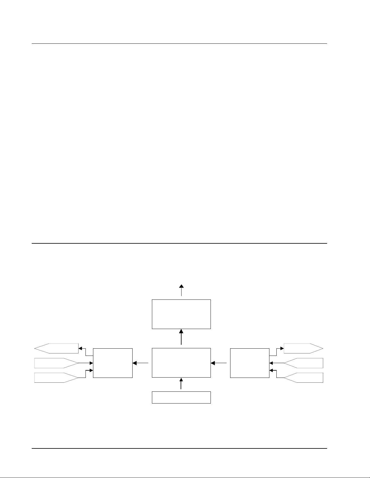
DMC-1500 Functional Elements
The DMC-1500 circuitry can be divided into the following functional groups as shown in Figure 1.1
and discussed in the following.
To
RS-232 / RS-422
Communication
80
8 Digital
8 Analog
8 TTL
I/
Interfac
Figure 1.1 - DMC-1500 Functional Elements
6834
Microcompute
256K
64K
128K EEPROM
Watch
Timer
To
GL-
4-
Motor/Encode
Interfac
Fro
Limit
Fro
Encoder
2 • Chapter 1 Overview DMC-1500
Page 15
Microcomputer Section
The main processing unit of the DMC-1500 is a specialized 32-bit Motorola 68340 Series
Microcomputer with 256K RAM, 64 K EPROM and 128 K bytes EEPROM. The RAM provides
memory for variables, array elements and application programs. The EPROM stores the firmware of
the DMC-1500. The EEPROM allows parameters and programs to be saved in non-volatile memory
upon power down.
Motor Interface
For each axis, a GL-1800 custom gate array performs quadrature decoding of the encoders at up to 8
MHz, generates the +/-10 Volt analog signal (16 Bit DAC) for input to a servo amplifier, and
generates step and direction signal for step motor drivers.
Communication
Communication to the DMC-1500 is via two separately addressable RS232 ports. The ports may also
be configured by the factory for RS422. The serial ports may be daisy-chained to other DMC-1500
controllers.
General I/O
The DMC-1500 provides interface circuitry for eight optoisolated inputs, eight general outputs and
seven analog inputs (12 Bit ADC with option for 16 Bit ADC).
1580
An auxiliary board, the DB-15072 provides interface to up to three OPTO 22 racks with 24 I/O
modules each. 24 bits can be configured for interface to output or input modules and the remaining 48
for input modules.
Controllers with 5 or more axes provide 24 inputs and 16 outputs.
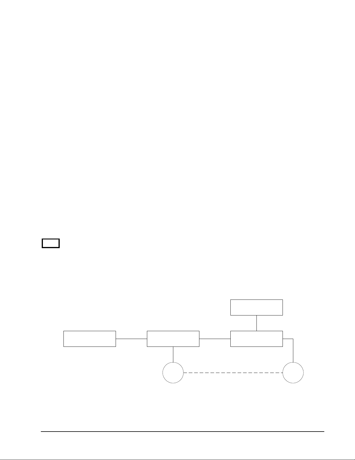
System Elements
As shown in Fig. 1.2, the DMC-1500 is part of a motion control system which includes amplifiers,
motors and encoders. These elements are described below
Power Supply
Computer DMC-1500 Controller Driver
Encoder Motor
Figure 1.2 - Elements of Servo systems
DMC-1500 Chapter 1 Overview • 3
Page 16

Motor
A motor converts current into torque which produces motion. Each axis of motion requires a motor
sized properly to move the load at the desired speed and acceleration. Galil's Motion Component
Selector software can help you calculate motor size and drive size requirements. Contact Galil at 800377-6329 if you would like this product.
The motor may be a step or servo motor and can be brush-type or brushless, rotary or linear. For step
motors, the controller can be configured to control full-step, half-step, or microstep drives.
Amplifier (Driver)
For each axis, the power amplifier converts a +/-10 Volt signal from the controller into current to
drive the motor. The amplifier should be sized properly to meet the power requirements of the motor.
For brushless motors, an amplifier that provides electronic commutation is required. The amplifiers
may be either pulse-width-modulated (PWM) or linear. They may also be configured for operation
with or without a tachometer. For current amplifiers, the amplifier gain should be set such that a 10
Volt command generates the maximum required current. For example, if the motor peak current is
10A, the amplifier gain should be 1 A/V. For velocity mode amplifiers, 10 Volts should run the motor
at the maximum speed.
For stepper motors, the amplifier converts step and direction signals into current.
Encoder or Position Sensor
An encoder translates motion into electrical pulses which are fed back into the controller. The DMC1500 accepts feedback from either a rotary or linear encoder. Typical encoders provide two channels
in quadrature, known as CHA and CHB. This type of encoder is known as a quadrature encoder.
Quadrature encoders may be either single-ended (CHA and CHB) or differential (CHA,CHA,CHB,CHB-). The DMC-1500 decodes either type into quadrature states or four times the number of
cycles. Encoders may also have a third channel (or index) for synchronization.
The DMC-1500 can also interface to encoders with pulse and direction signals.
There is no limit on encoder line density, however, the input frequency to the controller must not
exceed 2,000,000 full encoder cycles/second or 8,000,000 quadrature counts/sec. For example, if the
encoder line density is 10,000 cycles per inch, the maximum speed is 200 inches/second.
The standard voltage level is TTL (zero to five volts), however, voltage levels up to 12 Volts are
acceptable. If using differential signals, 12 Volts can be input directly to the DMC-1500. Singleended 12 Volt signals require a bias voltage input to the complementary inputs.
The DMC-1500 can accept analog feedback instead of an encoder for any axis. Note: the DMC-1580
controller must be modified by the factory to allow for analog feedback on axis H. For more
information see description of analog feedback in Chapter 2 under section entitled "Test the encoder
operation".
To interface with other types of position sensors such as resolvers or absolute encoders, Galil can
customize the controller and command set. Please contact Galil to talk to one of our applications
engineers about your particular system requirements.
Watch Dog Timer
The DMC-1500 provides an internal watch dog timer which checks for proper microprocessor
operation. The timer toggles the Amplifier Enable Output (AEN) which can be used to switch the
amplifiers off in the event of a serious DMC-1500 failure. The AEN output is normally high. During
power-up and if the microprocessor ceases to function properly, the AEN output will go low. The
4 • Chapter 1 Overview DMC-1500
Page 17

error light for each axis will also turn on at this stage. A reset is required to restore the DMC-1500 to
normal operation. Consult the factory for a Return Materials Authorization (RMA) Number if your
DMC-1500 is damaged.
DMC-1500 Chapter 1 Overview • 5
Page 18

THIS PAGE LEFT BLANK INTENTIONALLY
6 • Chapter 1 Overview DMC-1500
Page 19

Chapter 2 Getting Started
Elements You Need
Before you start, you will need the following system elements:
1. DMC-1500 Motion Controller and included cables, RS232, 60 pin ribbon cable and 26-pin
ribbon cable.
1a. For stepper motor operation, you will need an additional 20-pin ribbon cable, J4.
2. Servo motors with Optical Encoder (one per axis) or step motors
3. Power Amplifiers for motors
4. Power Supply for Amplifiers
5. PC (Personal Computer with RS232 port)
Software from Galil (Optional - but strongly recommended for first time users)
Communication Disk (COMMdisk)
-AND WSDK-16 Servo Design Software for Windows 3.1, and 3.11 for Workgroups
-OR WSDK-32 for Windows 95 or NT
ICM-1100 Interface Module (Optional, but strongly recommended). The Galil ICM-1100 is an
interconnect module with screw type terminals that directly interfaces to the DMC-1500 controller.
Note: An additional ICM-1100 is required for the DMC-1550 through DMC-1580.
The motors may be servo (brush type or brushless) or steppers. The amplifiers should be suitable for
the motor and may be linear or pulse-width-modulated. An amplifier may have current feedback or
voltage feedback.
For servo motors, the amplifiers should accept an analog signal in the +/-10 Volt range as a command.
The amplifier gain should be set so that a +10V command will generate the maximum required
current. For example, if the motor peak current is 10A, the amplifier gain should be 1 A/V. For
velocity mode amplifiers, a command signal of 10 Volts should run the motor at the maximum
required speed.
For step motors, the amplifiers should accept step and direction signals.
The WSDK software is highly recommended for first time users of the DMC-1500. It provides stepby-step instructions for system connection, tuning and analysis.
DMC-1500 Chapter 2 Getting Started • 7
Page 20

Installing the DMC-1500
Installation of a complete, operational DMC-1500 system consists of 9 steps.
Step 1. Determine overall motor configuration.
Step 2. Install jumpers on the DMC-1500.
Step 3. Configure the DIP switches on the DMC-1500.
Step 4. Connect AC power to controller
Step 5. Install communications software.
Step 6. Establish communications with Galil Software.
Step 7. Connect amplifiers and Encoders.
Step 8a. Connect standard servo motors.
Step 8b. Connect step motors.
Step 9. Tune the servo system
Step 1. Determine Overall Motor Configuration
Before setting up the motion control system, the user must determine the desired motor configuration.
The DMC-1500 can control any combination of standard servo motors, and stepper motors. Other
types of actuators, such as hydraulics can also be controlled, please consult Galil.
The following configuration information is necessary to determine the proper motor configuration:
1580
Standard Servo Motor Operation:
The DMC-1500 has been setup by the factory for standard servo motor operation providing an analog
command signal of +/- 10V. No hardware or software configuration is required for standard servo
motor operation.
Stepper Motor Operation:
To configure the DMC-1500 for stepper motor operation, the controller requires a jumper for each
stepper motor and the command, MT, must be given. The installation of the stepper motor jumper is
discussed in the following section entitled "Installing Jumpers on the DMC-1500". Further
instruction for stepper motor connections are discussed in Step 8b.
Step 2. Install Jumpers on the DMC-1500
The DMC-1500 has jumpers inside the controller box which may need to be installed. To access these
jumpers, the cover of the controller box must be removed. The following describes each of the
jumpers.
WARNING: Never open the controller box when AC power is applied to it.
For each axis that will be driving a stepper motor, a stepper mode (SM) jumper must be connected.
If you using a controller with more than 4 axis, you will have two pc-cards inside the controller box.
In this case, you will have 2 sets of stepper motor jumpers, one on each card. The jumpers on the
bottom card will be for axes X,Y,Z and W (or A,B,C, and D) and the top will be E,F,G and H. To
access the bottom card, the top card must be carefully removed.
8 • Chapter 2 Getting Started DMC-1500
Page 21

The stepper mode jumpers are located next to the GL-1800 which is the largest IC on the board. The
jumper set is labeled JP40 and the individual stepper mode jumpers are labeled SMX, SMY, SMZ,
SMW. The fifth jumper of the set, OPT, is for use by Galil technicians only.
The jumper set, J41, can be used to connect the controllers internal power supply to the optoisolated
inputs. This may be desirable if your system will be using limit switches, home inputs digital inputs,
or hardware abort and optoisolation is not necessary for your system. For a further explanation, see
section Bypassing the Opto-Isolation in Chapter 3.
Step 3. Configure DIP switches on the DMC-1500
Located on the outside of the controller box is a set of 5 DIP switches.
Switch 1 is the Master Reset switch. When this switch is on, the controller will perform a master reset
upon PC power up. Whenever the controller has a master reset, all programs and motion control
parameters stored in EEPROM will be ERASED. During normal operation, this switch should be off.
Switch 2,3 and 4 are used to configure the baud rate of the main RS232 serial port. See section
Configuration in Chapter 4.
Switch 5 is used to configure both serial ports for hardware handshake mode. Set this switch on for
handshake mode. Please note that the Galil communication software requires that hardware handshake
mode be enabled.
Step 4. Connect AC Power to the Controller
Before applying power, connect the 60-pin and 26-pin ribbons between the DMC-1500 and ICM-1100
interconnect module. The DMC-1500 requires a single AC supply voltage, single phase, 50 Hz or 60
Hz. from 90 volts to 260 volts.
WARNING: Dangerous voltages, current, temperatures and energy levels exist in this product
and in its associated amplifiers and servo motor(s). Extreme caution should be exercised in the
application of this equipment. Only qualified individuals should attempt to install, set up and
operate this equipment.
WARNING: Never open the controller box when AC power is applied to it.
Applying power will turn on the green light power indicator.
Step 5. Install Communications Software
After you have installed the DMC-1500 controller and turned the power on to your computer, you
should install software that enables communication between the controller and PC. There are several
ways to do this. The easiest way is to use the communication disks available from Galil
(COMMDISK VOL1 FOR DOS AND VOL2 FOR WINDOWS).
Using the COMMdisk Vol1 for Dos:
To use this disk, insert the COMMDISK VOL 1 in drive A. Type INSTALL and follow the
directions.
Using the COMMdisk Vol2 for Windows (16 bit and 32 bit versions):
For Windows3.x, run the installation program, setup16.exe. For Windows 95 or Windows NT, run
the installation program, setup32.exe.
DMC-1500 Chapter 2 Getting Started • 9
Page 22

Step 6. Establish Communications with Galil Software
Use the supplied 9-pin RS232 ribbon cable to connect the MAIN DMC-1500 serial port to your
computer or terminal at COMPORT 1. The DMC-1500 main serial port is configured as DATASET.
Your computer or terminal must be configured as a DATATERM for full duplex, no parity, 8 bits
data, one start bit and one stop bit.
Select the baud rate switches for 19.2 KB, 9600 B or 1200 B. The default setting is 19.2 KB.
Your computer needs to be configured as a "dumb" terminal which sends ASCII characters as they are
typed to the DMC-1500. The COMMdisk from Galil provides a terminal emulator program for your
computer. Follow the steps below to install and run the terminal emulator.
Dos Users:
To communicate with the DMC-1500, type TALK2DMC at the prompt. Once you have established
communication, the terminal display should show a colon, :. If you do not receive a colon, press the
carriage return. If a colon prompt is not returned, there is most likely an incorrect setting of the serial
communications port. The user must ensure that the correct communication port and baud rate are
specified when attempting to communicate with the controller. Please note that the serial port on the
controller must be set for handshake mode for proper communication with Galil software. The user
must also insure that the proper serial cable is being used, see appendix for pin-out of serial cable.
Windows Users:
In order for the windows software to communicate with a Galil controller, the controller must be
registered in the Galil Registry. The Galil Registry is simply a list of controllers. Registration consists
of telling the software the model of the controller, the address of the controller, and other information.
To do this, run the program DMCREG16 for Windows 3.x or DMCREG32 for Windows 95 and NT.
The DMCREG window will appear. Select Registry from the menu.
Note: If you are using DMCREG for the first time, no controllers will exist in the Ga lil Register. This
is normal.
The registry window is equipped with buttons to Add, Change, or Delete a controller. Pressing any
of these buttons will bring up the Set Registry Information window. (It should be noted that if you
wish to change information on any existing controller, it should be selected before clicking Change,
even if it is the only controller listed in the Registry.)
Use the Add button to add a new entry to the Registry. You will need to supply the Galil Controller
type. For any address changes to take effect, a model number must be entered. If you are changing an
existing controller, this field will already have an entry. If you are adding a controller, it will not.
Pressing the down arrow to the right of this field will reveal a menu of valid controller types. You
should choose DMC-1500. The registry information will show a default comm port of 2 and a default
baud rate of 9600 appears. This information should be changed as necessary to reflect the computers
comm port and the baud rate as set by the controller's DIP switches. The registry entry also displays
timeout and delay information. These are advanced parameters which should only be modified by
advanced users (see software documentation for more information).
Once you have set the appropriate Registry information for your controller, exit from the DMCREG
program. You will now be able to run communication software.
If you are using Windows 3.x, run the program DTERM16.EXE and if you are using Windows 95 or
Windows NT, run the program DTERM32.EXE. From the file menu, select Startup. You will now
see the registry information. Select the entry for your controller. Note: If you have only one entry,
you still must select this controller for the software to establish communications. Once the entry has
been selected, click on the OK button. If the software has successfully established communications
with the controller, the registry entry will be displayed at the top of the screen.
10 • Chapter 2 Getting Started DMC-1500
Page 23

If you are not properly communicating with the controller, the program will pause for 3-15 seconds.
The top of the screen will display the message “Status: not connected with Galil motion controller”
and the following error will appear: “STOP - Unable to establish communication with the Galil
controller. A time-out occurred while waiting for a response from the Galil controller.” If this
message appears, you must click OK. In this case, there is most likely an incorrect setting of the serial
communications port. The user must ensure that the correct communication port and baud rate are
specified when attempting to communicate with the controller. Please note that the serial port on the
controller must be set for handshake mode for proper communication with Galil software. The user
must also insure that the proper serial cable is being used, see appendix for pin-out of serial cable.
Once you establish communications, click on the menu for terminal and you will receive a colon
prompt. Communicating with the controller is described in later sections.
Sending Test Commands to the Terminal:
After you connect your terminal, press <carriage return> or the <enter> key on your keyboard. In
response to carriage return (CR), the controller responds with a colon, :
Now type
TPX (CR)
This command directs the controller to return the current position of the X axis. The controller should
respond with a number such as
0000000
The RS232 communication is established.
1580
Step 7. Connect Amplifiers and Encoders.
Once you have established communications between the software and the DMC-1500, you are ready
to connect the rest of the motion control system. The motion control system typically consists of an
ICM-1100 Interface Module, an amplifier for each axis of motion, and a motor to transform the current
from the amplifier into torque for motion. Galil also offers the AMP-11X0 series Interface Modules
which are ICM-1100’s equipped with servo amplifiers for brush type DC motors.
If you are using an ICM-1100, connect the 100-pin ribbon cable to the DMC-1500 and to the
connector located on the AMP-11X0 or ICM-1100 board. The ICM-1100 provides screw terminals
for access to the connections described in the following discussion.
Motion Controllers with more than 4 axes require a second ICM-1100 or AMP-11X0 and second 100pin cable.
System connection procedures will depend on system components and motor types. Any combination
of motor types can be used with the DMC-1500.
Here are the first steps for connecting a motion control system:
Step A. Connect the motor to the amplifier with no connection to the controller. Consult the
amplifier documentation for instructions regarding proper connections. Connect and
turn-on the amplifier power supply. If the amplifiers are operating properly, the motor
should stand still even when the amplifiers are powered up.
Step B. Connect the amplifier enable signal.
Before making any connections from the amplifier to the controller, you need to verify
that the ground level of the amplifier is either floating or at the same potential as earth.
WARNING: When the amplifier ground is not isolated from the power line or when it has a different
potential than that of the computer ground, serious damage may result to the computer controller
and amplifier.
DMC-1500 Chapter 2 Getting Started • 11
Page 24

If you are not sure about the potential of the ground levels, connect the two ground
signals (amplifier ground and earth) by a 10 KΩ resistor and measure the voltage across
the resistor. Only if the voltage is zero, connect the two ground signals directly.
The amplifier enable signal is used by the controller to disable the motor. It will disable
the motor when the watchdog timer activates, the motor-off command, MO, is given, or
the position error exceeds the error limit with the "Off-On-Error" function enabled (see
the command OE for further information).
The standard configuration of the AEN signal is TTL active high. In other words, the
AEN signal will be high when the controller expects the amplifier to be enabled. The
polarity and the amplitude can be changed if you are using the ICM-1100 interface
board. To change the polarity from active high (5 volts = enable, zero volts = disable) to
active low (zero volts = enable, 5 volts = disable), replace the 7407 IC with a 7406. Note
that many amplifiers designate the enable input as ‘inhibit’.
To change the voltage level of the AEN signal, note the state of the resistor pack on the
ICM-1100. When Pin 1 is on the 5V mark, the output voltage is 0-5V. To change to 12
volts, pull the resistor pack and rotate it so that Pin 1 is on the 12 volt side. If you
remove the resistor pack, the output signal is an open collector, allowing the user to
connect an external supply with voltages up to 24V.
On the ICM-1100, the amplifier enable signal is labeled AENX for the X axis. Connect
this signal to the amplifier (figure 2.3) and issue the command, MO, to disable the motor
amplifiers - often this is indicated by an LED on the amplifier.
Step C. Connect the encoders
For stepper motor operation, an encoder is optional.
For servo motor operation, if you have a preferred definition of the forward and reverse
directions, make sure that the encoder wiring is consistent with that definition.
The DMC-1500 accepts single-ended or differential encoder feedback with or without an
index pulse. If you are not using the AMP-11X0 or the ICM-1100 you will need to
consult the appendix for the encoder pinouts for connection to the motion controller. The
AMP-11X0 and the ICM-1100 can accept encoder feedback from a 10-pin ribbon cable
or individual signal leads. For a 10-pin ribbon cable encoder, connect the cable to the
protected header connector labeled X ENCODER (repeat for each axis necessary). For
individual wires, simply match the leads from the encoder you are using to the encoder
feedback inputs on the interconnect board. The signal leads are labeled XA+ (channel
A), XB+ (channel B), and XI+. For differential encoders, the complement signals are
labeled XA-, XB-, and XI-.
Note: When using pulse and direction encoders, the pulse signal is connected to CHA
and the direction signal is connected to CHB. The controller must be configured for
pulse and direction with the command CE. See the command summary for further
information on the command CE.
Step D. Verify proper encoder operation.
Start with the X encoder first. Once it is connected, turn the motor shaft and interrogate
the position with the instruction TPX <return>. The controller response will vary as the
motor is turned.
At this point, if TPX does not vary with encoder rotation, there are three possibilities:
1. The encoder connections are incorrect - check the wiring as necessary.
2. The encoder has failed - using an oscilloscope, observe the encoder signals. Verify that both channels
A and B have a peak magnitude between 5 and 12 volts. Note that if only one encoder channel fails,
12 • Chapter 2 Getting Started DMC-1500
Page 25

the position reporting varies by one count only. If the encoder failed, replace the encoder. If you
cannot observe the encoder signals, try a different encoder.
3. There is a hardware failure in the controller- connect the same encoder to a different axis. If the
problem disappears, you probably have a hardware failure. Consult the factory for help.
Step 8a. Connect Standard Servo Motors
The following discussion applies to connecting the DMC-1500 controller to standard servo motor
amplifiers:
The motor and the amplifier may be configured in the torque or the velocity mode. In the torque
mode, the amplifier gain should be such that a 10 Volt signal generates the maximum required current.
In the velocity mode, a command signal of 10 Volts should run the motor at the maximum required
speed.
Step by step directions on servo system setup are also included on the WSDK (Windows Servo Design
Kit) software offered by Galil. See section on WSDK for more details.
Step A. Check the Polarity of the Feedback Loop
It is assumed that the motor and amplifier are connected together and that the encoder is
operating correctly (Step B). Before connecting the motor amplifiers to the controller,
read the following discussion on setting Error Limits and Torque Limits. Note that this
discussion only uses the X axis as an examples.
Step B. Set the Error Limit as a Safety Precaution
Usually, there is uncertainty about the correct polarity of the feedback. The wrong
polarity causes the motor to run away from the starting position. Using a terminal
program, such as DMCTERM, the following parameters can be given to avoid system
damage:
Input the commands:
ER 2000 <CR> Sets error limit on the X axis to be 2000 encoder counts
OE 1 <CR> Disables X axis amplifier when excess position error exists
If the motor runs away and creates a position error of 2000 counts, the motor amplifier
will be disabled. Note: This function requires the AEN signal to be connected from the
controller to the amplifier.
Step C. Set Torque Limit as a Safety Precaution
To limit the maximum voltage signal to your amplifier, the DMC-1500 controller has a
torque limit command, TL. This command sets the maximum voltage output of the
controller and can be used to avoid excessive torque or speed when initially setting up a
servo system.
When operating an amplifier in torque mode, the voltage output of the controller will b e
directly related to the torque output of the motor. The user is responsible for determining
this relationship using the documentation of the motor and amplifier. The torque limit
can be set to a value that will limit the motors output torque.
When operating an amplifier in velocity or voltage mode, the voltage output of the
controller will be directly related to the velocity of the motor. The user is responsible for
determining this relationship using the documentation of the motor and amplifier. The
torque limit can be set to a value that will limit the speed of the motor.
For example, the following command will limit the output of the controller to 1 volt on
the X axis:
DMC-1500 Chapter 2 Getting Started • 13
Page 26

TL 1 <CR>
Note: Once the correct polarity of the feedback loop has been determined, the torque limit
should, in general, be increased to the default value of 9.99. The servo will not operate
properly if the torque limit is below the normal operating range. See description of TL in
the command reference.
Step D. Connect the Motor
Once the parameters have been set, connect the analog motor command signal (ACMD)
to the amplifier input.
To test the polarity of the feedback, command a move with the instruction:
PR 1000 <CR> Position relative 1000 counts
BGX <CR> Begin motion on X axis
When the polarity of the feedback is wrong, the motor will attempt to run away. The
controller should disable the motor when the position error exceeds 2000 counts. If the
motor runs away, the polarity of the loop must be inverted.
Note: Inverting the Loop Polarity
When the polarity of the feedback is incorrect, the user must invert the loop polarity and
this may be accomplished by several methods. If you are driving a brush-type DC motor,
the simplest way is to invert the two motor wires (typically red and black). For example,
switch the M1 and M2 connections going from your amplifier to the motor. When
driving a brushless motor, the polarity reversal may be done with the encoder. If you are
using a single-ended encoder, interchange the signal CHA and CHB. If, on the other
hand, you are using a differential encoder, interchange only CHA+ and CHA-. The loop
polarity and encoder polarity can also be affected through software with the MT, and CE
commands. For more details on the MT command or the CE command, see the
Command Reference section.
Note: Reversing the Direction of Motion
If the feedback polarity is correct but the direction of motion is opposite to the desired
direction of motion, reverse the motor leads AND the encoder signals.
When the position loop has been closed with the correct polarity, the next step is to adjust the PID
filter parameters, KP, KD and KI. It is necessary to accurately tune your servo system to ensure
fidelity of position and minimize motion oscillation as described in the next section .
14 • Chapter 2 Getting Started DMC-1500
Page 27
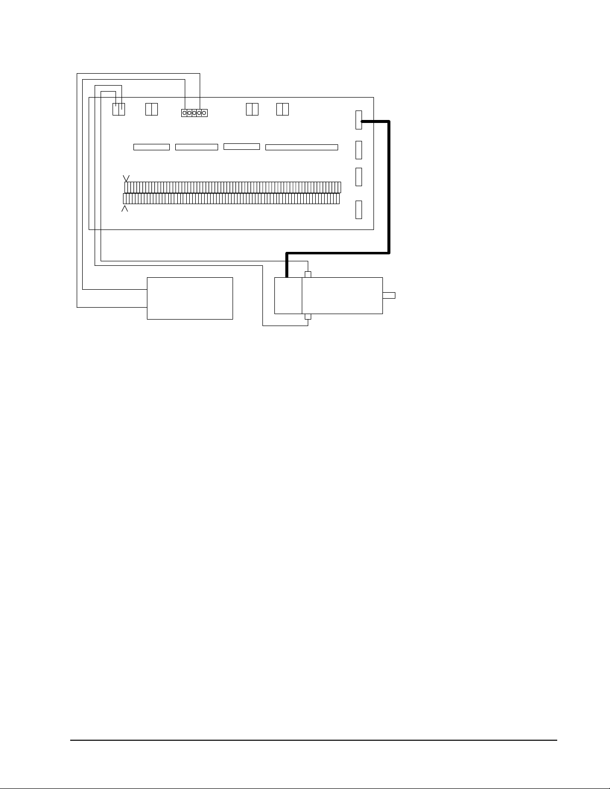
ICM-1100
J4
J5
J3
J2
Pin 2
Pin 1
red wire
black wire
+
CPS Power Supply
-
Screw Terminals
Encoder Ribbon Cable
(Typically Black Connector)
-
Galil
DC Servo Motor
Encoder
(Typically Red Connector)
+
W Encoder Z Encoder Y Encoder X Encoder
Figure 2-2 - System Connections with the AMP-1100Amplifier. Note: this figure shows a Galil Motor and
Encoder which uses a flat ribbon cable to connect to the AMP-1100 unit.
DMC-1500 Chapter 2 Getting Started • 15
Page 28
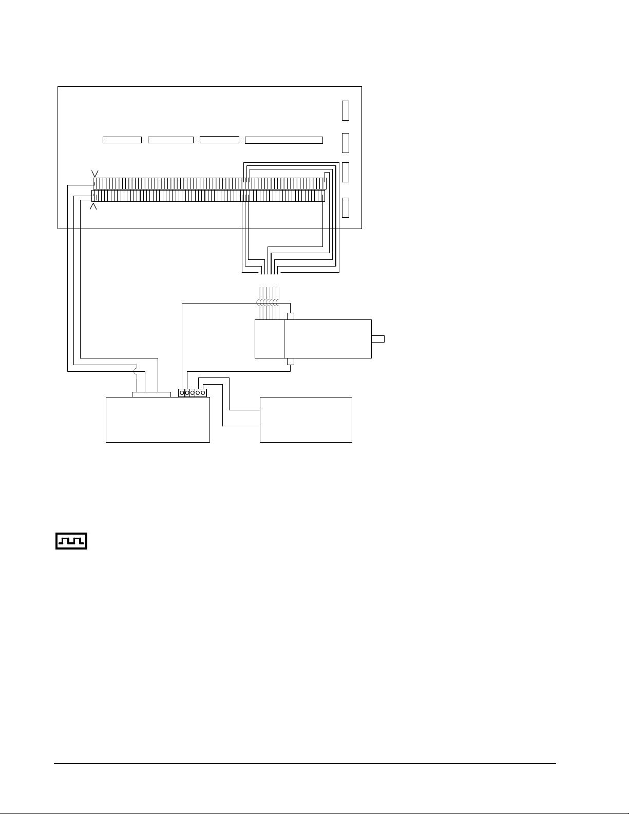
ICM-1100
ACMDX
GND
AENX
Pin 2
Pin 1
J4
J5
Screw Terminals
Encoder Wire Connections
Encoder: ICM-1100:
Channel A(+) XA+
Channel B(+) XB+
Channel A- XAChannel B- XBIndex Pulse XI+
Index Pulse - XI-
+Ref In 4
Inhibit* 11
Signal Gnd 2
MSA 12-80
Motor + 1
Motor - 2
Power Gnd 4
High Volt 5
J3
XI+ (81)
XB+ (79)
XA+ (77)
Encoder Wires
black wire
red wire
J2
+5V (103)
GND (104)
XI- (82)
XB- (80)
XA- (78)
(Typically Red Connector)
+
DC Servo Motor
Encoder
(Typically Black Connector)
-
-
CPS Power Supply
+
W Encoder Z Encoder Y Encoder X Encoder
Figure 2-3 System Connections with a separate amplifier (MSA 12-80). This diagram shows
the connections for a standard DC Servo Motor and encoder.
Step 8b. Connect Step Motors
In Stepper Motor operation, the pulse output signal has a 50% duty cycle. Step motors operate open
loop and do not require encoder feedback. When a stepper is used, the auxiliary encoder for the
corresponding axis is unavailable for an external connection. If an encoder is used for position
feedback, connect the encoder to the main encoder input corresponding to that axis. The commanded
position of the stepper can be interrogated with RP or DE. The encoder position can be interrogated
with TP.
The frequency of the step motor pulses can be smoothed with the filter parameter, KS. The KS
parameter has a range between 0.5 and 8, where 8 implies the largest amount of smoothing. See
Command Reference regarding KS.
The DMC-1500 profiler commands the step motor amplifier. All DMC-1500 motion commands apply
such as PR, PA, VP, CR and JG. The acceleration, deceleration, slew speed and smoothing are also
used. Since step motors run open-loop, the PID filter does not function and the position error is not
generated.
16 • Chapter 2 Getting Started DMC-1500
Page 29

To connect step motors with the DMC-1500 you must follow this procedure:
Step A. Install SM jumpers
Each axis of the DMC-1500 that will operate a stepper motor must have the
corresponding stepper motor jumper installed. For a discussion of SM jumpers, see step
2.
Step B. Connect step and direction signals.
Make connections from controller to motor amplifiers. (These signals are labeled
PULSX and DIRX for the x-axis on the ICM-1100). Consult the documentation for your
step motor amplifier.
Step C. Configure DMC-1500 for motor type using MT command. You can configure the
DMC-1500 for active high or active low pulses. Use the command MT 2 for active high
step motor pulses and MT -2 for active low step motor pulses. See description of the MT
command in the Command Reference.
Step 9. Tune the Servo System
Adjusting the tuning parameters is required when using servo motors. The system compensation
provides fast and accurate response. The following presentation suggests a simple and easy way for
compensation. More advanced design methods are available with software design tools from Galil,
such as the Servo Design Kit (SDK software )
The filter has three parameters: the damping, KD; the proportional gain, KP; and the integrator, KI.
The parameters should be selected in this order.
To start, set the integrator to zero with the instruction
KI 0 (CR) Integrator gain
and set the proportional gain to a low value, such as
KP 1 (CR) Proportional gain
KD 100 (CR) Derivative gain
For more damping, you can increase KD (maximum is 4095). Increase gradually and stop after the
motor vibrates. A vibration is noticed by audible sound or by interrogation. If you send the command
TE X (CR) Tell error
a few times, and get varying responses, especially with reversing polarity, it indicates system
vibration. When this happens, simply reduce KD.
Next you need to increase the value of KP gradually (maximum allowed is 1023). You can monitor the
improvement in the response with the Tell Error instruction
KP 10 (CR) Proportion gain
TE X (CR) Tell error
As the proportional gain is increased, the error decreases.
Again, the system may vibrate if the gain is too high. In this case, reduce KP. Typically, KP should
not be greater than KD/4. (Only when the amplifier is configured in the current mode).
Finally, to select KI, start with zero value and increase it gradually. The integrator eliminates the
position error, resulting in improved accuracy. Therefore, the response to the instruction
TE X (CR)
becomes zero. As KI is increased, its effect is amplified and it may lead to vibrations. If this occurs,
simply reduce KI. Repeat tuning for the Y, Z and W axes.
DMC-1500 Chapter 2 Getting Started • 17
Page 30

For a more detailed description of the operation of the PID filter and/or servo system theory, see
Chapter 10 - Theory of Operation.
Design Examples
Here are a few examples for tuning and using your controller. These examples have remarks next to
each command - these remarks must not be included in the actual program.
Example 1 - System Set-up
This example assigns the system filter parameters, error limits and enables the automatic error shut-off.
Instruction Interpretation
KP10,10,10,10,10,10,10,10 Set gains for A,B,C,D,E,and H axes
KP10,10,10,10,10,10,10,10 Set gains for A,B,C,D,E,and H axes
KP*=10 Alternate method for setting gain on all axes
KPX=10 Alternate method for setting X (or A) axis gain
KPA=10 Alternate method for setting A (or X) axis gain
1580
The X,Y,Z and W axes can also be referred to as the A,B,C, and D axes.
Instruction Interpretation
OE 1,1,1,1,1,1,1,1 Enable automatic Off on Error function for all axes
ER*=1000 Set error limit for all axes to 1000 counts
KP10,10,10,10,10,10,10,10 Set gains for A,B,C,D,E,and H axes
KP*=10 Alternate method for setting gain on all axes
KPX=10 Alternate method for setting X (or A) axis gain
KPA=10 Alternate method for setting A (or X) axis gain
KPZ=10 Alternate method for setting Z axis gain
KPD=10 Alternate method for setting D axis gain
KPH=10 Alternate method for setting H axis gain
Example 2 - Profiled Move
Objective: Rotate the X axis a distance of 10,000 counts at a slew speed of 20,000 counts/sec and an
acceleration and deceleration rates of 100,000 counts/s2. In this example, the motor turns and stops:
Instruction Interpretation
PR 10000 Distance
SP 20000 Speed
DC 100000 Deceleration
AC 100000 Acceleration
BG X Start Motion
18 • Chapter 2 Getting Started DMC-1500
Page 31

Example 3 - Multiple Axes
Objective: Move the four axes independently.
Instruction Interpretation
PR 500,1000,600,-400 Distances of X,Y,Z,W
SP 10000,12000,20000,10000 Slew speeds of X,Y,Z,W
AC 100000,10000,100000,100000 Accelerations of X,Y,Z,W
DC 80000,40000,30000,50000 Decelerations of X,Y,Z,W
BG XZ Start X and Z motion
BG YW Start Y and W motion
Example 4 - Independent Moves
The motion parameters may be specified independently as illustrated below.
Instruction Interpretation
PR ,300,-600 Distances of Y and Z
SP ,2000 Slew speed of Y
DC ,80000 Deceleration of Y
AC, 100000 Acceleration of Y
SP ,,40000 Slew speed of Z
AC ,,100000 Acceleration of Z
DC ,,150000 Deceleration of Z
BG Z Start Z motion
BG Y Start Y motion
Example 5 - Position Interrogation
The position of the four axes may be interrogated with the instruction, TP.
Instruction Interpretation
TP Tell position all four axes
TP X Tell position - X axis only
TP Y Tell position - Y axis only
TP Z Tell position - Z axis only
TP W Tell position - W axis only
The position error, which is the difference between the commanded position and the actual position
can be interrogated with the instruction TE.
Instruction Interpretation
TE Tell error - all axes
DMC-1500 Chapter 2 Getting Started • 19
Page 32

TE X Tell error - X axis only
TE Y Tell error - Y axis only
TE Z Tell error - Z axis only
TE W Tell error - W axis only
Example 6 - Absolute Position
Objective: Command motion by specifying the absolute position.
Instruction Interpretation
DP 0,2000 Define the current positions of X,Y as 0 and 2000
PA 7000,4000 Sets the desired absolute positions
BG X Start X motion
BG Y Start Y motion
After both motions are complete, the X and Y axes can be command back to zero:
PA 0,0 Move to 0,0
BG XY Start both motions
Example 7 - Velocity Control
Objective: Drive the X and Y motors at specified speeds.
Instruction Interpretation
JG 10000,-20000 Set Jog Speeds and Directions
AC 100000, 40000 Set accelerations
DC 50000,50000 Set decelerations
BG XY Start motion
after a few seconds, send the following command:
JG -40000 New X speed and Direction
TV X Returns X speed
and then
JG ,20000 New Y speed
TV Y Returns Y speed
These cause velocity changes including direction reversal. The motion can be stopped with the
instruction
ST Stop
Example 8 - Operation Under Torque Limit
The magnitude of the motor command may be limited independently by the instruction TL.
Instruction Interpretation
TL 0.2 Set output limit of X axis to 0.2 volts
JG 10000 Set X speed
BG X Start X motion
In this example, the X motor will probably not move since the output signal will not be sufficient to
overcome the friction. If the motion starts, it can be stopped easily by a touch of a finger.
20 • Chapter 2 Getting Started DMC-1500
Page 33

Increase the torque level gradually by instructions such as
Instruction Interpretation
TL 1.0 Increase torque limit to 1 volt.
TL 9.98 Increase torque limit to maximum, 9.98 Volts.
The maximum level of 10 volts provides the full output torque.
Example 9 - Interrogation
The values of the parameters may be interrogated. Some examples …
Instruction Interpretation
KP ? Return gain of X axis.
KP ,,? Return gain of Z axis.
KP ?,?,?,? Return gains of all axes.
Many other parameters such as KI, KD, FA, can also be interrogated. The command reference denotes
all commands which can be interrogated.
Example 10 - Operation in the Buffer Mode
The instructions may be buffered before execution as shown below.
Instruction Interpretation
PR 600000 Distance
SP 10000 Speed
WT 10000 Wait 10000 milliseconds before reading the next instruction
BG X Start the motion
Example 11 - Motion Programs
Motion programs may be edited and stored in the controllers on-board memory.
The instruction
ED Edit mode
moves the operation to the editor mode where the program may be written and edited. The ed itor
provides the line number. For example, in response to the first ED command, the first line is zero.
Line # Instruction Interpretation
000 #A Define label
001 PR 700 Distance
002 SP 2000 Speed
003 BGX Start X motion
004 EN End program
To exit the editor mode, input <cntrl>Q. The program may be executed with the command.
XQ #A Start the program running
DMC-1500 Chapter 2 Getting Started • 21
Page 34

Example 12 - Motion Programs with Loops
Motion programs may include conditional jumps as shown below.
Instruction Interpretation
#A Label
DP 0 Define current position as zero
V1=1000 Set initial value of V1
#Loop Label for loop
PA V1 Move X motor V1 counts
BG X Start X motion
AM X After X motion is complete
WT 500 Wait 500 ms
TP X Tell position X
V1=V1+1000 Increase the value of V1
JP #Loop,V1<10001 Repeat if V1<10001
EN End
After the above program is entered, quit the Editor Mode, <cntrl>Q. To start the motion, command:
XQ #A Execute Program #A
Example 13 - Motion Programs with Trippoints
The motion programs may include trippoints as shown below.
Instruction Interpretation
#B Label
DP 0,0 Define initial positions
PR 30000,60000 Set targets
SP 5000,5000 Set speeds
BGX Start X motion
AD 4000 Wait until X moved 4000
BGY Start Y motion
AP 6000 Wait until position X=6000
SP 2000,50000 Change speeds
AP ,50000 Wait until position Y=50000
SP ,10000 Change speed of Y
EN End program
To start the program, command:
XQ #B Execute Program #B
Example 14 - Control Variables
Objective: To show how control variables may be utilized.
Instruction Interpretation
#A;DP0 Label; Define current position as zero
PR 4000 Initial position
22 • Chapter 2 Getting Started DMC-1500
Page 35

SP 2000 Set speed
BGX Move X
AMX Wait until move is complete
WT 500 Wait 500 ms
#B
V1 = _TPX Determine distance to zero
PR -V1/2 Command X move 1/2 the distance
BGX Start X motion
AMX After X moved
WT 500 Wait 500 ms
V1= Report the value of V1
JP #C, V1=0 Exit if position=0
JP #B Repeat otherwise
#C Label #C
EN End of Program
To start the program, command
XQ #A Execute Program #A
This program moves X to an initial position of 1000 and returns it to zero on increments of half the
distance. Note, _TPX is an internal variable which returns the value of the X position. Internal
variables may be created by preceding a DMC-1500 instruction with an underscore, _.
Example 15 - Linear Interpolation
Objective: Move X,Y,Z motors distance of 7000,3000,6000, respectively, along linear trajectory.
Namely, motors start and stop together.
Instruction Interpretation
LM XYZ Specify linear interpolation axes
LI 7000,3000,6000 Relative distances for linear interpolation
LE Linear End
VS 6000 Vector speed
VA 20000 Vector acceleration
VD 20000 Vector deceleration
BGS Start motion
Example 16 - Circular Interpolation
Objective: Move the XY axes in circular mode to form the path shown on Fig. 2-4. Note that the
vector motion starts at a local position (0,0) which is defined at the beginning of any vector motion
sequence. See application programming for further information.
Instruction Interpretation
VM XY Select XY axes for circular interpolation
VP -4000,0 Linear segment
CR 2000,270,-180 Circular segment
VP 0,4000 Linear segment
DMC-1500 Chapter 2 Getting Started • 23
Page 36

Y
CR 2000,90,-180 Circular segment
VS 1000 Vector speed
VA 50000 Vector acceleration
VD 50000 Vector deceleration
VE End vector sequence
BGS Start motion
(-4000,4000) (0,4000)
R=2000
Figure 2-4 Motion Path for Example 16
(0,0) local zero(-4000,0)
X
24 • Chapter 2 Getting Started DMC-1500
Page 37

Chapter 3 Connecting Hardware
Overview
The DMC-1500 provides optoisolated digital inputs for forward limit, reverse limit, home, and abort
signals. The controller also has 8 optoisolated, uncommitted inputs (for general use) as well as 8 TTL
outputs and 7 analog inputs configured for voltages between +/- 10 volts.
1580
Controllers with 5 or more axes have an additional 8 TTL level inputs and 8 TTL level outputs.
This chapter describes the inputs and outputs and their proper connection.
To access the analog inputs or general inputs 5-8 or all outputs except OUT1, connect the 26-pin
ribbon cable to the 26-pin J5 IDC connector from the DMC-1500 to the AMP-11X0 or ICM-1100
board.
If you plan to use the auxiliary encoder feature of the DMC-1500, you must also connect a 20-pin
ribbon cable from the 20-pin J3 header connector on the DMC-1500 to the 26-pin J3 header connector
on the AMP-11X0 or ICM-1100. This cable is not shipped unless requested when ordering.
Using Opto-isolated Inputs
Limit Switch Input
The forward limit switch (FLSx) inhibits motion in the forward direction immediately upon activation
of the switch. The reverse limit switch (RLSx) inhibits motion in the reverse direction immediately
upon activation of the switch. If a limit switch is activated during motion, the controller will make a
decelerated stop using the deceleration rate previously set with the DC command. The motor will
remain in a servo state after the limit switch has been activated and will hold motor position.
When a forward or reverse limit switch is activated, the current application program that is running
will be interrupted and the controller will automatically jump to the #LIMSWI sub routine if one exists.
This is a subroutine which the user can include in any motion control program and is useful for
executing specific instructions upon activation of a limit switch.
After a limit switch has been activated, further motion in the direction of the limit switch will not be
possible until the logic state of the switch returns back to an inactive state. This usually involves
physically opening the tripped switch. Any attempt at further motion before the logic state has been
reset will result in the following error: “022 - Begin not possible due to limit switch” error.
The operands, _LFx and _LRx, return the state of the forward and reverse limit switches, respectively
(x represents the axis, X,Y,Z,W etc.). The value of the operand is either a ‘0’ or ‘1’ corresponding to
the logic state of the limit switch. Using a terminal program, the state of a limit switch can be printed
to the screen with the command, MG _LFx or MG _LFx. This prints the value of the limit switch
operands for the 'x' axis. The logic state of the limit switches can also be interro gated with the TS
command. For more details on TS see the Command Reference.
DMC-1500 Chapter 3 Connecting Hardware • 25
Page 38

Home Switch Input
The Home inputs are designed to provide mechanical reference points for a motion control application.
A transition in the state of a Home input alerts the controller that a particular reference point has been
reached by a moving part in the motion control system. A reference point can be a point in space or an
encoder index pulse.
The Home input detects any transition in the state of the switch and toggles between logic states 0 and
1 at every transition. A transition in the logic state of the Home input will cause the controller to
execute a homing routine specified by the user.
There are three homing routines supported by the DMC-1500: Find Edge (FE), Find Index (FI), and
Standard Home (HM).
The Find Edge routine is initiated by the command sequence: FEX <return>, BGX <return>. The Find
Edge routine will cause the motor to accelerate, then slew at constant speed until a transition is
detected in the logic state of the Home input. The motor will then decelerate to a stop. The
acceleration rate, deceleration rate and slew speed are specified by the user, prior to the movement,
using the commands AC, DC, and SP. It is recommended that a high deceleration value be used so
the motor will decelerate rapidly after sensing the Home switch.
The Find Index routine is initiated by the command sequence: FIX <return>, BGX <return>. Find
Index will cause the motor to accelerate to the user-defined slew speed (SP) at a rate specified by the
user with the AC command and slew until the controller senses a change in the index pulse signal from
low to high. The motor then decelerates to a stop at the rate previously specified by the user with the
DC command. Although Find Index is an option for homing, it is not dependent upon a transition in
the logic state of the Home input, but instead is dependent upon a transition in the level of the index
pulse signal.
The Standard Homing routine is initiated by the sequence of commands HMX <return>, BGX
<return>. Standard Homing is a combination of Find Edge and Find Index homing. Initiating the
standard homing routine will cause the motor to slew until a transition is detected in the logic state of
the Home input. The motor will accelerate at the rate specified by the command, AC, up to the slew
speed. After detecting the transition in the logic state on the Home Input, the motor will decelerate to
a stop at the rate specified by the command, DC. After the motor has decelerated to a stop, it switches
direction and approaches the transition point at the speed of 256 counts/sec. When the logic state
changes again, the motor moves forward (in the direction of increasing encoder count) at the same
speed, until the controller senses the index pulse. After detection, it decelerates to a stop and defines
this position as 0. The logic state of the Home input can be interrogated with the command MG
_HMX. This command returns a 0 or 1 if the logic state is low or high, respectively. The state of the
Home input can also be interrogated indirectly with the TS command.
For examples and further information about Homing, see command HM, FI, FE of the Command
Reference and the section entitled ‘Homing’ in the Programming Motion Section of this manual.
Abort Input
The function of the Abort input is to immediately stop the controller upon transition of the logic state.
NOTE: The response of the abort input is significantly different from the response of an activated
limit switch. When the abort input is activated, the controller stops generating motion commands
immediately, whereas the limit switch response causes the controller to make a decelerated stop.
NOTE: The effect of an Abort input is dependent on the state of the off-on-error function for each
axis. If the Off-On-Error function is enabled for any given axis, the motor for that axis will be turned
off when the abort signal is generated. This could cause the motor to ‘coast’ to a stop since it is no
longer under servo control. If the Off-On-Error function is disabled, the motor will decelerate to a
stop as fast as mechanically possible and the motor will remain in a servo state.
26 • Chapter 3 Connecting Hardware DMC-1500
Page 39

All motion programs that are currently running are terminated when a transition in the Abort input is
detected. For information on setting the Off-On-Error function, see the Command Reference, OE.
NOTE: The error LED does not light up when the Abort Input is active.
Uncommitted Digital Inputs
The DMC-1500 has 8 uncommitted opto-isolated inputs. These inputs are specified as INx where x
specifies the input number, 1 through 24. These inputs allow the user to monitor events external to the
controller. For example, the user may wish to have the x-axis motor move 1000 counts in the positive
direction when the logic state of IN1 goes high.
1580
Controllers with 5 or more axes have 16 opto-isolated inputs and 8 TTL level inputs. .
For controllers with more than 4 axes, the inputs 9-16 and the limit switch inputs for the additional
axes are accessed through the second 100-pin connector.
IN9-IN16 INCOM
FLE,RLE,HOMEE
FLF,RLF,HOMEF
FLG,RLG,HOMEG
FLH,RLH,HOMEH
A logic zero is generated when at least 1mA of current flows from the common to the input. A
positive voltage (with respect to the input) must be supplied at the common. This can be accomplished
by connecting a voltage in the range of +5V to +28V into INCOM of the input circuitry from a
separate power supply.
Wiring the Optoisolated Inputs
The default state of the controller configures all inputs to be interpreted as a logic one without any
connection. The inputs must be brought low to be interpreted as a zero. With regard to limit switches,
a limit switch is considered to be activated when the input is brought low (or a switch is closed to
ground). Some inputs can be configured to be active when the input is high - see section Changing
Optoisolated Inputs from Active High to Active Low.
The optoisolated inputs are organized into groups. For example, the general inputs, IN1-IN8, and the
ABORT input are one group. Each group has a common signal which supplies current for the inputs
in the group. In order to use an input, the associated common signal must be connected to voltage
between +5 and +28 volts, see discussion below.
LSCOM
The optoisolated inputs are connected in the following groups (these inputs are accessed through the
26-pin J5 header).
Group Common Signal
IN1-IN8, ABORT INCOM
FLX,RLX,HOMEX
FLY,RLY,HOMEY
FLZ,RLZ,HOMEZ
FLW,RLW,HOMEW
LSCOM
1580
For controllers with more than 4 axes, the inputs 9-16 and the limit switch inputs for the additional axes
are accessed through a separate connector, JD5.
Group Common Signal
DMC-1500 Chapter 3 Connecting Hardware • 27
Page 40

IN9-IN16 INCOM
FLE,RLE,HOMEE
FLF,RLF,HOMEF
FLG,RLG,HOMEG
FLH,RLH,HOMEH
A logic zero is generated when at least 1mA of current flows from the common signal to the input. A
positive voltage (with respect to the input) must be supplied at the common. This can be accomplished
by connecting a voltage in the range of +5V to +28V into INCOM of the input circuitry from a
separate power supply
LSCOM
LSCOM
FLSX
RLSX
HOMEX
FLSY
RLSY
HOMEY
INCOM
IN1 IN2 IN3 IN4 IN5 IN6
Figure 3-1. The Optoisolated Inputs
IN7 IN8 ABORT
Using an Isolated Power Supply
To take full advantage of opto-isolation, an isolated power supply should be used to provide the
voltage at the input common connection. When using an isolated power supply, do not connect the
ground of the isolated power to the ground of the controller. A power supply in the voltage range
between 5 to 28 Volts may be applied directly (see Figure 3-2). For voltages greater than 28 Volts, a
resistor, R, is needed in series with the input such that
28 • Chapter 3 Connecting Hardware DMC-1500
Page 41

1 mA < V supply/(R + 2.2KΩ) < 15 mA
y
f
(For Voltages > +28V)
LSCOM
2.2K
FLS
Figure 3-2. Connecting a single Limit or Home Switch to an Isolated Supply
Isolated
Suppl
NOTE: As stated in Chapter 2, the wiring is simplified when using the ICM-1100 or AMP-11x0
interface board. This board accepts the signals from the ribbon cables of the DMC-1500 and provides
phoenix-type screw terminals. A picture of the ICM-1100 can be seen on pg. 2-14. The user must
wire the system directly off the ribbon cable if the ICM-1100 or equivalent breakout board is not
available.
Bypassing the Opto-Isolation:
If no isolation is needed, the internal 5 Volt supply may be used to power the switches, as shown in
Figure 3-3. This can be done by connecting a jumper between the pins LSCOM or INCOM and 5V,
labeled J9. These jumpers can be added on either the ICM-1100 or the DMC-1500. This can also be
done by connecting wires between the 5V supply and common signals using the screw terminals on
the ICM-1100 or AMP-11x0.
To close the circuit, wire the desired input to any ground (GND) terminal.
DMC-1500 Chapter 3 Connecting Hardware • 29
Page 42

5V
LSCOM
FLS
GND
Figure 3-3 - Connecting Limit switches to the internal 5V supply
Changing Optoisolated Inputs From Active Low to Active High
Some users may prefer that the optoisolated inputs be active high. For example, the user may wish to
have the inputs be activated with a logic one signal. The limit, home and latch inputs can be
configured through software to be active high or low with the CN command. For more details on the
CN see Command Reference manual.
The Abort input cannot be configured in this manner.
Amplifier Interface
The DMC-1500 analog command voltage, ACMD, ranges between +/-10V. This signal, along with
GND, provides the input to the power amplifiers. The power amplifiers must be sized to drive the
motors and load. For best performance, the amplifiers should be configured for a current mode of
operation with no additional compensation. The gain should be set such that a 10 Volt input results in
the maximum required current.
The DMC-1500 also provides an amplifier enable signal, AEN. This signal changes under the
following conditions: the watchdog timer activates, the motor-off command, MO, is given, or the
OE1command (Enable Off-On-Error) is given and the position error exceeds the error limit. As
shown in Figure 3-4, AEN can be used to disable the amplifier for these conditions.
The standard configuration of the AEN signal is TTL active high. In other words, the AEN signal will
be high when the controller expects the amplifier to be enabled. The polarity and the amplitude can be
changed if you are using the ICM-1100 interface board. To change the polarity from active high (5
volts = enable, zero volts = disable) to active low (zero volts = enable, 5 volts= disable), replace the
7407 IC with a 7406. Note that many amplifiers designate the enable input as ‘inhibit’.
30 • Chapter 3 Connecting Hardware DMC-1500
Page 43

To change the voltage level of the AEN signal, note the state of the resistor pack on the ICM-1100.
r
When Pin 1 is on the 5V mark, the output voltage is 0-5V. To change to 12 volts, pull the resistor
pack and rotate it so that Pin 1 is on the 12 volt side. If you remove the resistor pack, the output signal
is an open collector, allowing the user to connect an external supply with voltages up to 24V.
7407 Open Collector
Buffer. The Enable signal
can be inverted by using
a 7406.
100-PIN
RIBBON
ICM-1100DMC-1500
+5V+12V
Connection to +5V or +12V made through
Resistor pack RP1. Removing the resistor
pack allows the user to connect their own
resistor to the desired voltage level ( Up to24V).
SERVO
AMPENX
MOTOR
AMPLIFIER
GND
ACMDX
Analog Switch
Figure 3-4 - Connecting AEN to the motor amplifier
TTL Inputs
1580
As previously mentioned, the DMC-1500 has 8 uncommitted TTL level inputs for controllers with 5 o
more axes. These are specified as INx where x ranges from 17 thru 24. The reset input is also a TTL
level, non-isolated signal and is used to locally reset the DMC-1500 without resetting the PC.
Analog Inputs
The DMC-1500 has seven analog inputs configured for the range between -10V and 10V. The inputs
are decoded by a 12-bit A/D converter giving a voltage resolution of approximately .005V. The
impedance of these inputs is 10 KΩ. The analog inputs are specified as AN[x] where x is a number 1
thru 7. Galil can supply the DMC-1500 with a 16-bit A/D converter as an option.
DMC-1500 Chapter 3 Connecting Hardware • 31
Page 44

TTL Outputs
The DMC-1500 provides eight general use outputs and an error signal output.
The general use outputs are TTL and are accessible by connections to OUT1 thru OUT8. These
outputs can be turned On and Off with the commands, SB (Set Bit), CB (Clear Bit), OB (Output Bit),
and OP (Output Port). For more information about these commands, see the Command Summary.
The value of the outputs can be checked with the operand _OP and the function @OUT[] (see Chapter
7, Mathematical Functions and Expressions).
1580
Controllers with 5 or more axes have an additional eight general use TTL outputs (connector JD5).
The error signal output is available on the main connector (J2, pin 3). This is a TTL signal which is
low when the controller has an error. This signal is not available through the phoenix connectors of
the ICM-1100.
Note: When the error signal is active, the LED on the controller will be on. An error condition
indicates one of the following conditions:
1. At least one axis has a position error greater than the error limit. The error limit is set by using the
command ER.
2. The reset line on the controller is held low or is being affected by noise.
3. There is a failure on the controller and the processor is resetting itself.
4. There is a failure with the output IC which drives the error signal.
Offset Adjustment
For each axis, the DMC-1500 provides offset correction potentiometers to compensate for any offset
in the analog output. These potentiometers have been adjusted at the factory to produce 0 Volts output
for a zero digital motor command. Before making any adjustment to the offset, send the motor off
command, MO, to the DMC-1500. This causes a zero digital motor command. Connect an
oscilloscope or voltmeter to the motor command pin. You should measure zero volts. If not, adjust
the offset potentiometer on the DMC-1500 until zero volts is observed.
32 • Chapter 3 Connecting Hardware DMC-1500
Page 45

Chapter 4 Communication
Introduction
The DMC-1500 has two RS232 ports. The main port is the data set and the auxiliary port is the data
term. The main port can be configured through the switches on the front panel, and the auxiliary port
can be configured with the software command CC. The auxiliary port can either be configur ed as a
general port or for daisy-chain communications. The auxiliary port configuration can be saved using
the Burn (BN) instruction. The RS232 ports also have a clock synchronizing line that allows
synchronization of motion on more than one controller.
RS232 Ports
The RS232 pin-out description for the main and auxiliary port is given below. Note, the auxiliary port
is essentially the same as the main port except inputs and outputs are reversed. The DMC-1500 may
also be configured by the factory for RS422. These pin-outs are also listed below.
Note: If you are connecting the RS232 auxiliary port to a terminal or any device which is a
DATATERM, it is necessary to use a connector adapter, which changes a dataterm to a dataset . This
cable is also known as a 'null' modem cable.
RS232 - Main Port {P1} DATATERM
1 CTS - output 6 CTS - output
2 Transmit Data - output 7 RTS - input
3 Receive Data - input 8 CTS - output
4 RTS - input 9 No connect (Can be connected to +5V or sample clock with jumpers)
5 Ground
RS232 - Auxiliary Port {P2} DATASET
1 CTS - input 6 CTS - input
2 Transmit Data - input 7 RTS - output
3 Receive Data - output 8 CTS - input
4 RTS - output 9 5V (Can be disconnected or connected to sample clock with jumpers)
5 Ground
*RS422 - Main Port {P1}
1 CTS - output 6 CTS+ output
2 Transmit Data - output 7 Transmit+ output
DMC-1500 Chapter 4 Communication • 33
Page 46

3 Receive Data - input 8 Receive+ input
4 RTS - input 9 RTS+ input
5 Ground
*RS422 - Auxiliary Port {P2}
1 CTS - input 6 CTS+ input
2 Receive Data - input 7 Receive+ input
3 Transmit Data - output 8 Transmit+ output
4 RTS - output 9 RTS+ output
5 Ground
*Default configuration is RS232. RS422 configuration available by factory.
Configuration
Configure your PC for 8-bit data, one start-bit, one stop-bit, full duplex and no parity. The baud rate
for the RS232 communication can be selected by setting the proper switch configuration on the front
panel according to the table below.
Baud Rate Selection
Switch Setting Interpretation
1200 9600 19.2K
ON ON OFF 300 Baud rate
ON OFF OFF 1200 Baud rate
ON OFF ON 4800 Baud rate
OFF ON OFF 9600 Baud rate
OFF OFF ON 19200 Baud rate
OFF ON ON 38400 Baud
ON ON ON SELF TEST
The RS232 main port can be configured for handshake or non-handshake mode. Set the HSHK switch
to ON to select the handshake mode. In this mode, the RTS and CTS lines are used. The CTS line
will go high whenever the DMC-1500 is not ready to receive additional characters. The RTS line will
inhibit the DMC-1500 from sending additional characters. Note, the RTS line goes high for inhibit.
The handshake should be turned on to ensure proper communication especially at higher baud rates.
The auxiliary port of the DMC-1500 can be configured either as a general port or for the daisy-chain.
When configured as a general port, the port can be commanded to send ASCII messages to another
DMC-1500 controller or to a display terminal or panel.
(Configure Communication ) at port 2. The command is in the format of:
CC m,n,r,p
where m sets the baud rate, n sets for either handshake or non-handshake mode, r sets for general port
or the auxiliary port, and p turns echo on or off.
m - Baud Rate - 300,1200,4800,9600,19200,38400
n - Handshake - 0=No; 1=Yes
r - Mode - 0=General Port; 1=Daisy-chain
34 • Chapter 4 Communication DMC-1500
Page 47

p - Echo - 0=Off; 1=On; Valid only if r=0
Note, for the handshake of the auxiliary port, the roles for the RTS and CTS lines are rev ersed .
Example:
CC 1200,0,0,1
Configure auxiliary communication port for 1200 baud, no handshake, general port
mode and echo turned on.
Daisy-Chaining
Up to eight DMC-1500 controllers may be connected in a daisy-chain allowing for multiple controllers
to be commanded from a single serial port. One DMC-1500 is connected to the host terminal via the
RS232 at port 1 or the main port. Port 2 or the auxiliary port of that DMC-1500 is then brought into
port 1 of the next DMC-1500, and so on. The address of each DMC-1500 is configured by setting the
three address jumpers (ADR4,ADR2,ADR1) located inside the box near the main processor IC.
When connecting multiple controllers in a daisy-chain, the cable between controllers should be made
to female 0.89 with all wires connected straight through.
0
2
ADR1 represents the
eight possible addresses, 0 through 7, are set as follows:
ADR4 ADR2 ADR1 ADDRESS
bit, ADR2 represents 21 bit, and ADR4 represents 22 bit of the address. The
OFF OFF OFF 0
OFF OFF ON 1
OFF ON OFF 2
OFF ON ON 3
ON OFF OFF 4
ON OFF ON 5
ON ON OFF 6
ON ON ON 7
To communicate with any one of the DMC-1500 units, give the command “%A”, where A is the
address of the board. All instructions following this command will be sent only to the board with that
address. Only when a new %A command is given will the instruction be sent to another board. The
only exception is "!" command. To talk to all the DMC-1500 boards in the daisy-chain at one time,
insert the character "!" before the software command. All boards receive the command, but only
address 0 will echo.
Note: The CC command must be specified to configure the port P2 of each unit.
Daisy Chain Example:
Objective: Control a 7-axis motion system using two controllers, a DMC-1540 4 axis controller and a
DMC-1530 3 axis controller. Address 0 is the DMC-1540 and address 1 is the DMC-1530.
Desired motion profile:
Address 0 (DMC-1540) X Axis is 500 counts
Y Axis is 1000 counts
Z Axis is 2000 counts
W Axis is 1500 counts
Address 1 (DMC-1530) X Axis is 700 counts
Y Axis is 1500 counts
DMC-1500 Chapter 4 Communication • 35
Page 48

Command Interpretation
%0 Talk only to controller 0 (DMC-1540)
PR 500,1000,2000,1500 Specify X,Y,Z,W distances
%1 Talk only to controller board 1 (DMC-1530)
PR 700,1500,2500 Specify X,Y,Z distances
!BG Begin motion on both controllers
Synchronizing Sample Clocks
It is possible to synchronize the sample clocks of all DMC-1500's in the daisy-chain. This involves
burning in the command, TM-1, in all DMC-1500's except for one DMC-1500 which will be the
source. It is also necessary to put a jumper on pins 7 and 9 of the JP30 and JP31 jumper blocks.
Controller Response to DATA
Most DMC-1500 instructions are represented by two characters followed by the appropriate
parameters. Each instruction must be terminated by a carriage return or semicolon.
Instructions are sent in ASCII, and the DMC-1500 decodes each ASCII character (one byte) one at a
time. It takes approximately .5 msec for the controller to decode each command. However, the PC
can send data to the controller at a much faster rate because of the FIFO buffer.
Z Axis is 2500 counts
After the instruction is decoded, the DMC-1500 returns a colon (:) if the instruction was valid or a
question mark (?) if the instruction was not valid.
For instructions that return data, such as Tell Position (TP), the DMC-1500 will return the data
followed by a carriage return, line feed and : .
It is good practice to check for : after each command is sent to prevent errors. An echo function is
provided to enable associating the DMC-1500 response with the data sent. The echo is enabled by
sending the command EO 1 to the controller.
Galil Software Tools and Libraries
API (Application Programming Interface) software is available from Galil. The API software is
written in C and is included in the Galil COMM disks. They can be used for development under DOS
and Windows environments (16 and 32 bit Windows). With the API's, the user can incorporate
already existing library functions directly into a C program.
Galil has also developed a Visual Basic Toolkit. This provides VBXs, 16-bit OCXs and 3 2-bit OCXs
for handling all of the DMC-1500 communications including support of interrupts. These objects
install directly into Visual Basic and are part of the run-time environment. For more information,
contact Galil.
36 • Chapter 4 Communication DMC-1500
Page 49

Chapter 5 Command Basics
Introduction
The DMC-1500 provides over 100 commands for specifying motion and machine parameters.
Commands are included to initiate action, interrogate status and config ure the digital filter.
The DMC-1500 instruction set is BASIC-like and easy to use. Instructions consist of two uppercase
letters that correspond phonetically with the appropriate function. For example, the instruction BG
begins motion, and ST stops the motion.
Commands can be sent "live" over the bus for immediate execution by the DMC-1500, or an entire
group of commands can be downloaded into the DMC-1500 memory for execution at a later time.
Combining commands into groups for later execution is referred to as Applications Programming and
is discussed in the following chapter.
This section describes the DMC-1500 instruction set and syntax. A summary of commands as well as
a complete listing of all DMC-1500 instructions is included in the Command Reference Manual.
Command Syntax
DMC-1500 instructions are represented by two ASCII upper case characters followed by applicable
arguments. A space may be inserted between the instruction and arguments. A semicolon or <enter>
is used to terminate the instruction for processing by the DMC-1500 command interpreter. Note: If
you are using a Galil terminal program, commands will not be processed until an <enter> command is
given. This allows the user to separate many commands on a single line and not begin execution until
the user gives the <enter> command.
IMPORTANT: All DMC-1500 commands must be sent in upper case.
For example, the command
PR 4000 <enter> Position relative
PR is the two character instruction for position relative. 4000 is the argument which represents the
required position value in counts. The <enter> terminates the instruction. The space between PR and
4000 is optional.
For specifying data for the X,Y,Z and W axes, commas are used to separate the axes. If no data is
specified for an axis, a comma is still needed as shown in the examples below. If no data is specified
for an axis, the previous value is maintained. The space between the data and instruction is optional.
For controllers with 5 or more axes, the axes are referred to as A,B,C,D,E,F,G,H where X,Y,Z,W and
A,B,C,D may be used interchangeably.
The DMC-1500 provides an alternative method for specifying data. Here data is specified individually
using a single axis specifier such as X,Y,Z or W (or A,B,C,D,E,F,G or H for the DMC-1580). An
equals sign is used to assign data to that axis. For example:
DMC-1500 Chapter 5 Command Basics • 37
Page 50

PRX=1000 Specify a position relative movement for the X axis of 1000
ACY=200000 Specify acceleration for the Y axis as 200000
Instead of data, some commands request action to occur on an axis or group of axes. For example, ST
XY stops motion on both the X and Y axes. Commas are not required in this case since the particular
axis is specified by the appropriate letter X Y Z or W. If no parameters follow the instruction, action
will take place on all axes. Here are some examples of syntax for requesting action:
BG X Begin X only
BG Y Begin Y only
BG XYZW Begin all axes
BG YW Begin Y and W only
BG Begin all axes
1580
For controllers with 5 or more axes, the axes are referred to as A,B,C,D,E,F,G,H. The specifiers
X,Y,Z,W and A,B,C,D may be used interchangeably:
BG ABCDEFGH Begin all axes
BG D Begin D only
Coordinated Motion with more than 1 axis
When requesting action for coordinated motion, the letter S is used to specify the coordinated motion.
For example:
BG S Begin coordinated sequence
BG SW Begin coordinated sequence and W axis
Program Syntax
Chapter 7 explains the how to write and execute motion control programs.
Controller Response to DATA
The DMC-1500 returns a : for valid commands.
The DMC-1500 returns a ? for invalid commands.
For example, if the command BG is sent in lower case, the DMC-1500 will return a ?.
:bg <enter> invalid command, lower case
? DMC-1500 returns a ?
When the controller receives an invalid command the user can request the error code. The error code
will specify the reason for the invalid command response. To request the error code type the
command: TC1 For example:
38 • Chapter 5 Command Basics DMC-1500
Page 51

?TC1 <enter> Tell Code command
1 Unrecognized command Returned response
There are many reasons for receiving an invalid command response. The most common reasons are:
unrecognized command (such as typographical entry or lower case), command given at improper time
(such as during motion), or a command out of range (such as exceeding maximum speed). A complete
list of all error codes can be found with the description of the TC command in the Command
Reference Manual.
Interrogating the Controller
Interrogation Commands
The DMC-1500 has a set of commands that directly interrogate the controller. When the command is
entered, the requested data is returned in decimal format on the next line followed by a carriage return
and line feed. The format of the returned data can be changed using the Position Format (PF),
Variable Format (VF) and Leading Zeros (LZ) command. See Chapter 7 and the Command Reference
Manual.
Summary of Interrogation Commands
RP Report Command Position
RL Report Latch
∧R ∧
V
SC Stop Code
TB Tell Status
TC Tell Error Code
TD Tell Dual Encoder
TE Tell Error
TI Tell Input
TP Tell Position
TR Trace
TS Tell Switches
TT Tell Torque
TV Tell Velocity
Firmware Revision Information
For example, the following example illustrates how to display the current position of the X axis:
TP X <enter> Tell position X
0000000000 Controllers Response
TP XY <enter> Tell position X and Y
0000000000,0000000000 Controllers Response
DMC-1500 Chapter 5 Command Basics • 39
Page 52

Additional Interrogation Methods.
Most commands can be interrogated by using a question mark. For information specific to a particular
axis, type the command followed by a ? for each axis requested.
PR ?,?,?,? Request X,Y,Z,W values
PR ,? Request Y value only
The controller can also be interrogated with operands.
Operands
Most DMC-1500 commands have corresponding operands that can be used for interrogation.
Operands must be used inside of valid DMC expressions. For example, to display the value of an
operand, the user could use the command:
MG ‘operand’ where 'operand' is a valid DMC operand
All of the command operands begin with the underscore character (_). For example, the value of the
current position on the X axis can be assigned to the variable, V, with the command:
V=_TPX
The Command Reference denotes all commands which have an equivalent operand as "Used as an
Operand". For further information, see description of operands in Chapter 7.
Command Summary
For a complete command summary, see Command Reference manual.
40 • Chapter 5 Command Basics DMC-1500
Page 53

Chapter 6 Programming Motion
Overview
The DMC-1500 can be commanded to do the following modes of motion: Absolute and relative
independent positioning, jogging, linear interpolation (up to 8 axes), linear and circular interpolation
(2 axes with 3
These modes are discussed in the following sections.
The DMC-1510 is a single axis controller and uses X-axis motion only. Likewise, the DMC-1520
uses X and Y, the DMC-1530 uses X,Y and Z, and the DMC-1540 uses X,Y,Z and W. The DMC1550 uses A,B,C,D, and E. The DMC-1560 uses A,B,C,D,E, and F. The DMC-1570 uses
A,B,C,D,E,F and G. The DMC-1580 uses the axes A,B,C,D,E,F,G, and H.
The example applications described below will help guide you to the appropriate mode of motion.
rd
axis of tangent motion), electronic gearing, electronic cam motion and contouring.
1580
For controllers with 5 or more axes, the specifiers, ABCDEFGH, are used. XYZ and W may be
interchanged with ABCD.
Independent Axis Positioning
In this mode, motion between the specified axes is independent, and each axis follows its own profile.
The user specifies the desired absolute position (PA) or relative position (PR), slew speed (SP),
acceleration ramp (AC), and deceleration ramp (DC), for each axis. On begin (BG), the DMC-1500
profiler generates the corresponding trapezoidal or triangular velocity profile and position trajectory.
The controller determines a new command position along the trajectory every sample period until the
specified profile is complete. Motion is complete when the last position command is sent by the
DMC-1500 profiler. Note: The actual motor motion may not be complete when the profile has been
completed, however, the next motion command may be specified.
The Begin (BG) command can be issued for all axes either simultaneously or independently. XYZ or
W axis specifiers are required to select the axes for motion. When no axes are specified, this causes
motion to begin on all axes.
The speed (SP) and the acceleration (AC) can be changed at any time during motion, however, the
deceleration (DC) and position (PR or PA) cannot be changed until motion is complete. Remember,
motion is complete when the profiler is finished, not when the actual motor is in position. The Stop
command (ST) can be issued at any time to decelerate the motor to a stop before it reaches its final
position.
An incremental position movement (IP) may be specified during motion as long as the additional move
is in the same direction. Here, the user specifies the desired position increment, n. The new target is
equal to the old target plus the increment, n. Upon receiving the IP command, a revised profile will be
generated for motion towards the new end position. The IP command does not require a begin. Note:
If the motor is not moving, the IP command is equivalent to the PR and BG command combination.
DMC-1500 Chapter 6 Programming Motion • 41
Page 54

Command Summary - Independent Axis
COMMAND DESCRIPTION
PR X,Y,Z,W Specifies relative distance
PA x,y,z,w Specifies absolute position
SP x,y,z,w Specifies slew speed
AC x,y,z,w Specifies acceleration rate
DC x,y,z,w Specifies deceleration rate
BG XYZW Starts motion
ST XYZW Stops motion before end of move
IP x,y,z,w Changes position target
IT x,y,z,w Time constant for independent motion smoothing
AM XYZW Trippoint for profiler complete
MC XYZW Trippoint for "in position"
The lower case specifiers (x,y,z,w) represent position values for each axis. For controllers with more
than 4 axes, the position values would be represented as a,b,c,d,e,f,g,h.
Operand Summary - Independent Axis
OPERAND DESCRIPTION
_ACx Return acceleration rate for the axis specified by ‘x’
_DCx Return deceleration rate for the axis specified by ‘x’
_SPx Returns the speed for the axis specified by ‘x’
_PAx Returns current destination if ‘x’ axis is moving, otherwise returns the current commanded
position if in a move.
_PRx Returns current incremental distance specified for the ‘x’ axis
Example - Absolute Position Movement
PA 10000,20000 Specify absolute X,Y position
AC 1000000,1000000 Acceleration for X,Y
DC 1000000,1000000 Deceleration for X,Y
SP 50000,30000 Speeds for X,Y
BG XY Begin motion
42 • Chapter 6 Programming Motion DMC-1500
Page 55

Example - Multiple Move Sequence
Required Motion Profiles:
X-Axis 500 counts Position
10000 count/sec Speed
500000 counts/sec2 Acceleration
Y-Axis 1000 counts Position
15000 count/sec Speed
500000 counts/sec2 Acceleration
Z-Axis 100 counts Position
5000 counts/sec Speed
500000 counts/sec Acceleration
This example will specify a relative position movement on X, Y and Z axes. The movement on each
axis will be separated by 20 msec. Fig. 6.1 shows the velocity profiles for the X,Y and Z axis.
#A Begin Program
PR 2000,500,100 Specify relative position movement of 1000, 500 and 100 counts for X,Y and Z
axes.
SP 15000,10000,5000 Specify speed of 10000, 15000, and 5000 counts / sec
AC 500000,500000,500000 Specify acceleration of 500000 counts / sec
DC 500000,500000,500000 Specify deceleration of 500000 counts / sec
BG X Begin motion on the X axis
WT 20 Wait 20 msec
BG Y Begin motion on the Y axis
WT 20 Wait 20 msec
BG Z Begin motion on Z axis
EN End Program
VELOCITY
(COUNTS/SEC)
2
for all axes
2
for all axes
X axis velocity profile
20000
Y axis velocity profile
15000
Z axis velocity profile
10000
5000
TIME (ms)
0
20
40 60
80
100
Figure 6.1 - Velocity Profiles of XYZ
DMC-1500 Chapter 6 Programming Motion • 43
Page 56

Notes on fig 6.1: The X and Y axis have a ‘trapezoidal’ velocity profile, while the Z axis has a
‘triangular’ velocity profile. The X and Y axes accelerate to the specified speed, move at this constant
speed, and then decelerate such that the final position agrees with the command position, PR. The Z
axis accelerates, but before the specified speed is achieved, must begin deceleration such that the axis
will stop at the commanded position. All 3 axes have the same acceleration and deceleration rate,
hence, the slope of the rising and falling edges of all 3 velocity profiles are the same.
Independent Jogging
The jog mode of motion allows the user to change speed, direction and acceleration during motion.
The user specifies the jog speed (JG), acceleration (AC), and the deceleration (DC) rate for each axis.
The direction of motion is specified by the sign of the JG parameters. When the begin command is
given (BG), the motor accelerates up to speed and continues to jog at that speed until a new speed or
stop (ST) command is issued. If the jog speed is changed during motion, the controller will make a
accelerated (or decelerated) change to the new speed.
An instant change to the motor position can be made with the use of the IP command. Upon receiving
this command, the controller commands the motor to a position which is equal to the specified
increment plus the current position. This command is useful when trying to synchronize the position
of two motors while they are moving.
Note that the controller operates as a closed-loop position controller while in the jog mode. The
DMC-1500 converts the velocity profile into a position trajectory and a new position target is
generated every sample period. This method of control results in precise speed regulation with phase
lock accuracy.
Command Summary - Jogging
COMMAND DESCRIPTION
AC x,y,z,w Specifies acceleration rate
BG X,Y,Z,W Begins motion
DC x,y,z,w Specifies deceleration rate
IP x,y,z,w Increments position instantly
IT x,y,z,w Time constant for independent motion smoothing
JG +/-x,y,z,w Specifies jog speed and direction
ST XYZW Stops motion
Parameters can be set with individual axes specifiers such as JGY+2000(set jog speed for X axis to
2000) or ACYH=40000 (set acceleration for Y and H axes to 400000) .
Operand Summary - Independent Axis
OPERAND DESCRIPTION
_ACx Return acceleration rate for the axis specified by ‘x’
_DCx Return deceleration rate for the axis specified by ‘x’
_SPx Returns the jog speed for the axis specified by ‘x’
_TVx Returns the actual velocity of the axis specified by ‘x’ (averaged over.25 sec)
44 • Chapter 6 Programming Motion DMC-1500
Page 57

Example - Jog in X Only
Jog X motor at 50000count/s. After X motor is at its jog speed, begin jogging Z in reverse direction at
25000 count/s.
#A
AC 20000,,20000 Specify X,Z acceleration of 20000 cts/sec
DC 20000,,20000 Specify X,Z deceleration of 20000 cts/sec
JG 50000,,-25000 Specify jog speed and direction for X and Z axis
BG XY Begin X motion
AS X Wait until X is at speed
BG Z Begin Z motion
EN
Example - Joystick Jogging
The jog speed can also be changed using an analog input such as a joystick. Assume that for a 10 Volt
input the speed must be 50000 counts/sec.
#JOY Label
JG0 Set in Jog Mode
BGX Begin motion
#B Label for Loop
V1 = @AN[1] Read analog input
VEL = V1*50000/2047 Compute speed
JG VEL Change JG speed
JP #B Loop
Linear Interpolation Mode
The DMC-1500 provides a linear interpolation mode for 2 or more axes (up to 8 axes for the DMC-
1580). In linear interpolation mode, motion between the axes is coordinated to maintain the prescribed
vector speed, acceleration, and deceleration along the specified path. The motion path is described in
terms of incremental distances for each axis. An unlimited number of incremental segments may be
given in a continuous move sequence, making the linear interpolation mode ideal for following a
piece-wise linear path. There is no limit to the total move length.
The LM command selects the Linear Interpolation mode and axes for interpolation. For example, LM
YZ selects only the Y and Z axes for linear interpolation.
When using the linear interpolation mode, the LM command only needs to be specified once unless
the axes for linear interpolation change.
Specifying Linear Segments
The command LI x,y,z,w or LI a,b,c,d,e,f,g,h specifies the incremental move distance for each axis.
This means motion is prescribed with respect to the current axis position. Up to 511 incremental move
segments may be given prior to the Begin Sequence (BGS) command. Once motion has begun,
additional LI segments may be sent to the controller.
The clear sequence (CS) command can be used to remove LI segments stored in the buffer prior to the
start of the motion. To stop the motion, use the instructions STS or AB. The command, ST, causes a
decelerated stop. The command, AB, causes an instantaneous stop and aborts the program, and the
command AB1 aborts the motion only.
DMC-1500 Chapter 6 Programming Motion • 45
Page 58

The Linear End (LE) command must be used to specify the end of a linear move sequence. This
command tells the controller to decelerate to a stop following the last LI command. If an LE
command is not given, an Abort AB1 must be used to abort the motion sequence.
It is the responsibility of the user to keep enough LI segments in the DMC-1500 sequence buffer to
ensure continuous motion. If the controller receives no additional LI segments and no LE command,
the controller will stop motion instantly at the last vector. There will be no controlled deceleration.
LM? or _LM returns the available spaces for LI segments that can be sent to the buffer. 511 returned
means the buffer is empty and 511 LI segments can be sent. A zero means the buffer is full and no
additional segments can be sent. As long as the buffer is not full, additional LI segments can be sent at
PC bus speeds.
The instruction _CS returns the segment counter. As the segments are processed, _CS increases,
starting at zero. This function allows the host computer to determine which segment is being
processed.
Specifying Vector Acceleration, Deceleration and Speed:
The commands VS n, VA n, and VD n are used to specify the vector speed, acceleration and
deceleration. The DMC-1500 computes the vector speed based on the axes specified in the LM mode.
For example, LM XYZ designates linear interpolation for the X,Y and Z axes. The vector speed for
this example would be computed using the equation:
VS2=XS2+YS2+ZS2, where XS, YS and ZS are the speed of the X,Y and Z axes.
The controller always uses the axis specifications from LM, not LI, to compute the speed.
In cases where the acceleration causes the system to 'jerk', the DMC-1500 provides a vector motion
smoothing function. VT is used to set the S-curve smoothing constant for coordinated moves.
Additional Commands
The DMC-1500 provides commands for additional control of vector motion and program control.
Note: Many of the commands used in Linear Interpolation motion also applies Vector motion
described in the next section.
Trippoints
The command AV n is the ‘After Vector’ trippoint, which halts program execution until the vector
distance of n has been reached.
In this example, the XY system is required to perform a 90
the corner, we use the AV 4000 trippoint, which slows the speed to 1000 count/s. Once the motors
reach the corner, the speed is increased back to 4000 cts / s.
Instruction Interpretation
#LMOVE Label
DP ,,0,0 Define position of Z and W axes to be 0
LMXY Define linear mode between X and Y axes.
LI 5000,0 Specify first linear segment
LI 0,5000 Specify second linear segment
LE End linear segments
VS 4000 Specify vector speed
BGS Begin motion sequence
° turn. In order to slow the speed around
46 • Chapter 6 Programming Motion DMC-1500
Page 59

AV 4000 Set trippoint to wait until vector distance of 4000 is reached
VS 1000 Change vector speed
AV 5000 Set trippoint to wait until vector distance of 5000 is reached
VS 4000 Change vector speed
EN Program end
Specifying Vector Speed for Each Segment
The instruction VS has an immediate effect and, therefore, must be given at the required time. In some
applications, such as CNC, it is necessary to attach various speeds to different motion segments. This
can be done by the instruction
LI x,y,z,w < n
This instruction attaches the vector speed, n, to the motion segment LI. As a consequence, the
program #LMOVE can be written in the alternative form:
Instruction Interpretation
#ALT Label for alternative program
DP 0,0 Define Position of X and Y axis to be 0
LMXY Define linear mode between X and Y axes.
LI 4000,0 <4000 Specify first linear segment with a vector speed of 4000
LI 1000,0 < 1000 Specify second linear segment with a vector speed of 1000
LI 0,5000 < 4000 Specify third linear segment with a vector speed of 4000
LE End linear segments
BGS Begin motion sequence
EN Program end
Changing Feedrate:
The command VR n allows the feedrate, VS, to be scaled between 0 and 10 with a resolution of .0001.
This command takes effect immediately and causes VS to be scaled. VR also applies when the vector
speed is specified with the ‘<’ operator. This is a useful feature for feedrate override. VR does not
ratio the accelerations. For example, VR .5 results in the specification VS 2000 to be divided in half.
Command Summary - Linear Interpolation
COMMAND DESCRIPTION
LM xyzw
LM abcdefgh
LM? Returns number of available spaces for linear segments in DMC-1500 sequence buffer.
LI x,y,z,w < n
LI a,b,c,d,e,f,g,h < n
VS n Specify vector speed
VA n Specify vector acceleration
VD n Specify vector deceleration
VR n Specify the vector speed ratio
BGS Begin Linear Sequence
CS Clear sequence
Specify axes for linear interpolation
(same) controllers with 5 or more axes
Zero means buffer full. 512 means buffer empty.
Specify incremental distances relative to current position, and assign vector speed n.
DMC-1500 Chapter 6 Programming Motion • 47
Page 60

LE Linear End- Required at end of LI command sequence
S
LE? Returns the length of the vector (resets after 2147483647)
AMS Trippoint for After Sequence complete
AV n Trippoint for After Relative Vector Distance, n
VT S curve smoothing constant for vector moves
Operand Summary - Linear Interpolation
OPERAND DESCRIPTION
_AV Return distance traveled
_CS Segment counter - returns number of the segment in the sequence, starting at zero.
_LE Returns length of vector (resets after 2147483647)
_LM Returns number of available spaces for linear segments in DMC-1500 sequence buffer.
Zero means buffer full. 512 means buffer empty.
_VPm Return the absolute coordinate of the last data point along the trajectory.
(m=X,Y,Z or W or A,B,C,D,E,F,G or H)
To illustrate the ability to interrogate the motion status, consider the first motion segment of our
example, #LMOVE, where the X axis moves toward the point X=5000. Suppose that when X=3000,
the controller is interrogated using the command ‘MG _AV’. The returned value will be 3000. The
value of _CS, _VPX and _VPY will be zero.
Now suppose that the interrogation is repeated at the second segment when Y=2000. The value of
_AV at this point is 7000, _CS equals 1, _VPX=5000 and _VPY=0.
Example - Linear Move
Make a coordinated linear move in the ZW plane. Move to coordinates 40000,30000 counts at a
vector speed of 100000 counts/sec and vector acceleration of 1000000 counts/sec2.
Instruction Interpretation
#TEST Label
LM ZW Specify axes for linear interpolation
LI,,40000,30000 Specify ZW distances
LE Specify end move
VS 100000 Specify vector speed
VA 1000000 Specify vector acceleration
VD 1000000 Specify vector deceleration
BGS Begin sequence
AMS After motion sequence ends
EN End program
Note that the above program specifies the vector speed, VS, and not the actual axis speeds VZ and
VW. The axis speeds are determined by the DMC-1500 from:
V
48 • Chapter 6 Programming Motion DMC-1500
22
VZ VW=+
Page 61

The resulting profile is shown in Figure 6.2.
30000
27000
POSITIO N W
3000
0
FEEDRATE
VELOCITY
Z-AXIS
VELOCITY
W-AXIS
0 40000
0 0.1 0.5 0.6
4000 36000
POSITIO N Z
TIME (sec)
TIME (sec)
TIME (sec)
Figure 6.2 - Linear Interpolation
Example - Multiple Moves
This example makes a coordinated linear move in the XY plane. The Arrays VX and VY are used to
store 750 incremental distances which are filled by the program #LOAD.
Instruction Interpretation
DMC-1500 Chapter 6 Programming Motion • 49
Page 62

#LOAD Load Program
DM VX [750],VY [750] Define Array
COUNT=10 Initialize Counter
N=10 Initialize position increment
#LOOP LOOP
VX [COUNT]=N Fill Array VX
VY [COUNT]=N Fill Array VY
N=N+10 Increment position
COUNT=COUNT+1 Increment counter
JP #LOOP,COUNT<750 Loop if array not full
#A Label
LM XY Specify linear mode for XY
COUNT=0 Initialize array counter
#LOOP2;JP#LOOP2,_LM=0 If sequence buffer full, wait
JS#C,COUNT=500 Begin motion on 500th segment
LI
VX[COUNT],VY[COUNT]
COUNT=COUNT+1 Increment array counter
JP #LOOP2,COUNT<750 Repeat until array done
LE End Linear Move
AMS After Move sequence done
MG "DONE" Send Message
EN End program
#C;BGS;EN Begin Motion Subroutine
Specify linear segment
Vector Mode: Linear and Circular Interpolation Motion
The DMC-1500 allows a long 2-D path consisting of linear and arc segments to be prescribed. Motion
along the path is continuous at the prescribed vector speed even at transitions between linear and
circular segments. The DMC-1500 performs all the complex computations of linear and circular
interpolation, freeing the host PC from this time intensive task.
The coordinated motion mode is similar to the linear interpolation mode. Any pair of two axes may be
selected for coordinated motion consisting of linear and circular segments. In addition, a third axis can
be controlled such that it remains tangent to the motion of the selected pair of axes. Note that only one
pair of axes can be specified for coordinated motion at any given time.
The command VM m,n,p where ‘m’ and ‘n’ are the coordinated pair and p is the tangent axis (Note:
the commas which separate m,n and p are not necessary). For example, VM XWZ selects the XW
axes for coordinated motion and the Z-axis as the tangent.
Specifying Vector Segments
The motion segments are described by two commands; VP for linear segments and CR for circular
segments. Once a set of linear segments and/or circular segments have been specified, the sequence is
ended with the command VE. This defines a sequence of commands for coordinated motion.
Immediately prior to the execution of the first coordinated movement, the controller defines the current
position to be zero for all movements in a sequence. Note: This ‘local’ definition of zero does not
affect the absolute coordinate system or subsequent coordinated motion sequences.
50 • Chapter 6 Programming Motion DMC-1500
Page 63

The command, VP xy specifies the coordinates of the end points of the vector movement with respect
to the starting point. Non-sequential axes do not require comma delineation. The command, CR r,q,d
define a circular arc with a radius r, starting angle of q, and a traversed angle d. The notation for q is
that zero corresponds to the positive horizontal direction, and for both q and d, the counter-clockwise
(CCW) rotation is positive.
Up to 511 segments of CR or VP may be specified in a single sequence and must be ended with the
command VE. The motion can be initiated with a Begin Sequence (BGS) command. Once motion
starts, additional segments may be added.
The Clear Sequence (CS) command can be used to remove previous VP and CR commands which
were stored in the buffer prior to the start of the motion. To stop the motion, use the in structions STS
or AB1. ST stops motion at the specified deceleration. AB1 aborts the motion instantaneously.
The Vector End (VE) command must be used to specify the end of the coordinated motion. This
command requires the controller to decelerate to a stop following the last motion requirement. If a VE
command is not given, an Abort (AB1) must be used to abort the coordinated motion sequence.
It is the responsibility of the user to keep enough motion segments in the DMC-1500 sequence buffer
to ensure continuous motion. If the controller receives no additional motion segments and no VE
command, the controller will stop motion instantly at the last vector. There will be no controlled
deceleration. LM? or _LM returns the available spaces for motion segments that can be sent to the
buffer. 511 returned means the buffer is empty and 511 segments can be sent. A zero means the
buffer is full and no additional segments can be sent. As long as the buffer is not full, additional
segments can be sent at PC bus speeds.
The operand _CS can be used to determine the value of the segment counter.
Specifying Vector Acceleration, Deceleration and Speed:
The commands VS n, VA n, and VD n are used to specify the vector speed, acceleration and
deceleration. The DMC-1500 computes the vector speed based on the two axes specified in the VM
mode. For example, VM YZ designates vector mode for the Y and Z axes. The vector speed for this
example would be computed using the equation:
VS2=YS2+ZS2, where YS and ZS are the speed of the Y and Z axes.
In cases where the acceleration causes the system to 'jerk', the DMC-1500 provides a vector motion
smoothing function. VT is used to set the S-curve smoothing constant for coordinated moves.
Additional Commands
The DMC-1500 provides commands for additional control of vector motion and program control.
Note: Many of the commands used in Vector Mode motion also applies Linear Interpolation motion
described in the previous section.
Trippoints
The command AV n is the ‘After Vector’ trippoint, which halts program execution until the vector
distance of n has been reached.
Specifying Vector Speed for Each Segment
The vector speed may be specified by the immediate command VS. It can also be attached to a motion
segment with the instructions
VP x,y, < n
CR r,
DMC-1500 Chapter 6 Programming Motion • 51
θ,δ < n
Page 64

Both cases assign a vector speed of n count/s to the corresponding motion segment.
Changing Feedrate:
The command VR n allows the feedrate, VS, to be scaled between 0 and 10 with a resolution of .0001.
This command takes effect immediately and causes VS scaled. VR also applies when the vector speed
is specified with the ‘<’ operator. This is a useful feature for feedrate override. VR does not ratio the
accelerations. For example, VR .5 results in the specification VS 2000 to be divided in half.
Compensating for Differences in Encoder Resolution:
By default, the DMC-1500 uses a scale factor of 1:1 for the encoder resolution when used in vector
mode. If this is not the case, the command, ES can be used to scale the encoder counts. The ES
command accepts two arguments which represent the number of counts for the two encoders used for
vector motion. The smaller ratio of the two numbers will be multiplied by the higher resolution
encoder. For more information, see ES command in Chapter 11, Command Summary.
Tangent Motion:
Several applications, such as cutting, require a third axis (i.e. a knife blade), to remain tangent to the
coordinated motion path. To handle these applications, the DMC-1500 allows one axis to be specified
as the tangent axis. The VM command provides parameter specifications for describing the
coordinated axes and the tangent axis.
VM m,n,p m,n specifies coordinated axes p specifies tangent axis such as X,Y,Z,W or
A,B,C,D,E,F,G,H p=N turns off tangent axis
Before the tangent mode can operate, it is necessary to assign an axis via the VM command and define
its offset and scale factor via the TN m,n command. m defines the scale factor in counts/degree and n
defines the tangent position that equals zero degrees in the coordinated motion plane. The _TN can be
used to return the initial position of the tangent axis.
Example - XY Table Control
Assume an XY table with the Z-axis controlling a knife. The Z-axis has a 2000 quad counts/rev
encoder and has been initialized after power-up to point the knife in the +Y direction. A 180
cut is desired, with a radius of 3000, center at the origin and a starting point at (3000,0). The motion is
CCW, ending at (-3000,0). Note that the 0
corresponds to the position -500 in the Z-axis, and defines the offset. The motion has two parts. First,
X,Y and Z are driven to the starting point, and later, the cut is performed. Assume that the knife is
engaged with output bit 0.
Instruction Interpretation
#EXAMPLE Example program
VM XYZ XY coordinate with Z as tangent
TN 2000/360,-500 2000/360 counts/degree, position -500 is 0 degrees in XY plane
CR 3000,0,180 3000 count radius, start at 0 and go to 180 CCW
VE End vector
CB0 Disengage knife
PA 3000,0,_TN Move X and Y to starting position, move Z to initial tangent position
BG XYZ Start the move to get into position
° position in the XY plane is in the +X direction. This
° circular
52 • Chapter 6 Programming Motion DMC-1500
Page 65

AM XYZ When the move is complete
SB0 Engage knife
WT50 Wait 50 msec for the knife to engage
BGS Do the circular cut
AMS After the coordinated move is complete
CB0 Disengage knife
MG "ALL DONE"
EN End program
Command Summary - Vector Mode Motion
COMMAND DESCRIPTION
VM m,n Specifies the axes for the planar motion where m and n represent the planar axes and p is
the tangent axis.
VP m,n Return coordinate of last point, where m=X,Y,Z or W.
CR r,Θ, ±ΔΘ Specifies arc segment where r is the radius, Θ is the starting angle and ΔΘ is the travel
angle. Positive direction is CCW.
VS n Specify vector speed or feedrate of sequence.
VA n Specify vector acceleration along the sequence.
VD n Specify vector deceleration along the sequence.
VR n Specify vector speed ratio
BGS Begin motion sequence.
CS Clear sequence.
AV n Trippoint for After Relative Vector distance, n.
AMS Holds execution of next command until Motion Sequence is complete.
TN m,n Tangent scale and offset.
ES m,n Ellipse scale factor.
VT S curve smoothing constant for coordinated moves
LM? Return number of available spaces for linear and circular segments in DMC-1500
sequence buffer. Zero means buffer is full. 512 means buffer is empty.
Operand Summary - Vector Mode Motion
OPERAND DESCRIPTION
_VPM The absolute coordinate of the axes at the last intersection along the sequence.
_AV Distance traveled.
_LM Number of available spaces for linear and circular segments in DMC-1500 sequence
buffer. Zero means buffer is full. 512 means buffer is empty.
_CS Segment counter - Number of the segment in the sequence, starting at zero.
_VE Vector length of coordinated move sequence.
When AV is used as an operand, _AV returns the distance traveled along the sequence.
The operands _VPX and _VPY can be used to return the coordinates of the last point specified along
the path.
DMC-1500 Chapter 6 Programming Motion • 53
Page 66

Example:
Traverse the path shown in Fig. 6.3. Feedrate is 20000 counts/sec. Plane of motion is XY
Instruction Interpretation
VM XY Specify motion plane
VS 20000 Specify vector speed
VA 1000000 Specify vector acceleration
VD 1000000 Specify vector deceleration
VP -4000,0 Segment AB
CR 1500,270,-180 Segment BC
VP 0,3000 Segment CD
CR 1500,90,-180 Segment DA
VE End of sequence
BGS Begin Sequence
The resulting motion starts at the point A and moves toward points B, C, D, A. Suppose that we
interrogate the controller when the motion is halfway between the points A and B.
The value of _AV is 2000
The value of _CS is 0
_VPX and _VPY contain the absolute coordinate of the point A
Suppose that the interrogation is repeated at a point, halfway between the points C and D.
The value of _AV is 4000+1500
The value of _CS is 2
_VPX,_VPY contain the coordinates of the point C
C (-4000,3000)
R = 1500
B (-4000,0)
Figure 6.3 - The Required Path
Electronic Gearing
π+2000=10,712
D (0,3000)
A (0,0)
This mode allows up to 8 axes to be electronically geared to one master axis. The master may rotate in
both directions and the geared axes will follow at the specified gear ratio. The gear ratio may be
different for each axis and changed during motion.
54 • Chapter 6 Programming Motion DMC-1500
Page 67

The command GAX or GAY or GAZ or GAW (or GAA or GAB or GAC or GAD or GAE or GAF or
GAG or GAH for DMC-1580) specifies the master axis. There may only be one master. GR x,y,z,w
specifies the gear ratios for the slaves where the ratio may be a number between +/-127.9999 with a
fractional resolution of .0001. GR 0,0,0,0 turns off electronic gearing for any set of axes. A limit
switch will also disable electronic gearing for that axis. GR causes the specified axes to be geared to
the actual position of the master. The master axis is commanded with motion commands such as PR,
PA or JG.
When the master axis is driven by the controller in the jog mode or an independent motion mode, it is
possible to define the master as the command position of that axis, rather than the actual position. The
designation of the commanded position master is by the letter, C. For example, GACX indicates that
the gearing is the commanded position of X.
An alternative gearing method is to synchronize the slave motor to the commanded vector motion of
several axes performed by GAS. For example, if the X and Y motor form a circular motion, the Z axis
may move in proportion to the vector move. Similarly, if X,Y and Z perform a linear interpolation
move, W can be geared to the vector move.
Electronic gearing allows the geared motor to perform a second independent or coordinated move in
addition to the gearing. For example, when a geared motor follows a master at a ratio of 1:1, it may be
advanced an additional distance with PR, or JG, commands, or VP, or LI.
Command Summary - Electronic Gearing
COMMAND DESCRIPTION
GA n Specifies master axis for gearing where:
n = X,Y,Z or W or A,B,C,D,E,F,G,H for main encoder as master
n = XC,YC,ZC or WC or AC, BC, CC, DC, EC, FC,GC,HC for commanded position.
n = DX,DY,DZ or DW or DA, DB, DC, DD, DE, DF,DG,DH for auxiliary encoders
n = S vector move as master
GR x,y,z,w Sets gear ratio for slave axes. 0 disables electronic gearing for specified axis.
GR a,b,c,d,e,f,g,h Sets gear ratio for slave axes. 0 disables electronic gearing for specified axis.
MR x,y,z,w Trippoint for reverse motion past specified value. Only one field may be used.
MF x,y,z,w Trippoint for forward motion past specified value. Only one field may be used.
Operand Summary - Electronic Gearing
COMMAND DESCRIPTION
GA n Specifies master axis for gearing where:
n = X,Y,Z or W or A,B,C,D,E,F,G,H for main encoder as master
n = XC,YC,ZC or WC or AC, BC, CC, DC, EC, FC,GC,HC for commanded position.
n = DX,DY,DZ or DW or DA, DB, DC, DD, DE, DF,DG,DH for auxiliary encoders
n = S vector move as master
GR x,y,z,w Sets gear ratio for slave axes. 0 disables electronic gearing for specified axis.
GR a,b,c,d,e,f,g,h Sets gear ratio for slave axes. 0 disables electronic gearing for specified axis.
MR x,y,z,w Trippoint for reverse motion past specified value. Only one field may be used.
MF x,y,z,w Trippoint for forward motion past specified value. Only one field may be used.
DMC-1500 Chapter 6 Programming Motion • 55
Page 68

Example - Simple Master Slave
Master axis moves 10000 counts at slew speed of 100000 counts/sec. Y is defined as the master.
X,Z,W are geared to master at ratios of 5,-.5 and 10 respectively.
Instruction Interpretation
GAY Specify master axes as Y
GR 5,,-.5,10 Set gear ratios
PR ,10000 Specify Y position
SP ,100000 Specify Y speed
BGY Begin motion
Example - Electronic Gearing
Objective: Run two geared motors at speeds of 1.132 and -0.045 times the speed of an external master.
The master is driven at speeds between 0 and 1800 RPM (2000 counts/rev encoder).
Solution: Use a DMC-1530 controller, where the Z-axis is the master and X and Y are the geared
axes.
MO Z Turn Z off, for external master
GA Z Specify master axis
GR 1.132,-.045 Specify gear ratios
Now suppose the gear ratio of the X-axis is to change on-the-fly to 2. This can be achieved by
commanding:
GR 2 Specify gear ratio for X axis to be 2
In applications where both the master and the follower are controlled by the DMC-1500 controller, it
may be desired to synchronize the follower with the commanded position of the master, rather than the
actual position. This eliminates the coupling between the axes which may lead to oscillations.
For example, assume that a gantry is driven by two axes, X,Y, on both sides. The X-axis is the master
and the Y-axis is the follower. To synchronize Y with the commanded position of X, use the
instructions:
GA XC Specify master as commanded position of X
GR,1 Set gear ratio for Y as 1:1
PR 3000 Command X motion
BG X Start motion on X axis
You may also perform profiled position corrections in the electronic gearing mode. Suppose, for
example, that you need to advance the slave 10 counts. Simply command
IP ,10 Specify an incremental position movement of 10 on Y axis.
Under these conditions, this IP command is equivalent to:
PR,10 Specify position relative movement of 10 on Y axis
BGY Begin motion on Y axis
Often the correction is quite large. Such requirements are common when synchronizing cutting knives
or conveyor belts.
Example - Synchronize two conveyor belts with trapezoidal velocity correction.
Instruction Interpretation
56 • Chapter 6 Programming Motion DMC-1500
Page 69

GAX Define master axis as X
GR,2 Set gear ratio 2:1 for Y
PR,300 Specify correction distance
SP,5000 Specify correction speed
AC,100000 Specify correction acceleration
DC,100000 Specify correction deceleration
BGY Start correction
Electronic Cam
The electronic cam is a motion control mode which enables the periodic synchronization of several
axes of motion. Up to 7 axes can be slaved to one master axis. The master axis encoder must be input
through a main encoder port.
The electronic cam is a more general type of electronic gearing which allows a table-based relationship
between the axes. It allows synchronizing all the controller axes. For example, the DMC-1580
controller may have one master and up to seven slaves. To simplify the presentation, we will limit the
description to a 4-axis controller.
To illustrate the procedure of setting the cam mode, consider the cam relationship for th e slave axis Y,
when the master is X. Such a graphic relationship is shown in Figure 6.8.
Step 1. Selecting the master axis
The first step in the electronic cam mode is to select the master axis. This is done with the instruction
EAp where p = X,Y,Z,W
p is the selected master axis
Step 2. Specify the master cycle and the change in the slave axis(es).
In the electronic cam mode, the position of the master is always expressed modulo one cycle. In this
example, the position of x is always expressed in the range between 0 and 6000. Similarly, the slave
position is also redefined such that it starts at zero and ends at 1500. At the end of a cycle when the
master is 6000 and the slave is 1500, the positions of both x and y are redefined as zero. To specify
the master cycle and the slave cycle change, we use the instruction EM.
EM x,y,z,w
where x,y,z,w specify the cycle of the master and the total change of the slaves over one cycle.
The cycle of the master is limited to 8,388,607 whereas the slave change per cycle is limited to
2,147,483,647. If the change is a negative number, the absolute value is specified. For the given
example, the cycle of the master is 6000 counts and the change in the slave is 1500. Therefore, we use
the instruction:
DMC-1500 Chapter 6 Programming Motion • 57
Page 70

EM 6000,1500
Step 3. Specify the master interval and starting point.
Next we need to construct the ECAM table. The table is specified at uniform intervals of master
positions. Up to 256 intervals are allowed. The size of the master interval and the starting point are
specified by the instruction:
EP m,n
where m is the interval width in counts, and n is the starting point.
For the given example, we can specify the table by specifying the position at the master points of 0,
2000, 4000 and 6000. We can specify that by
EP 2000,0
Step 4. Specify the slave positions.
Next, we specify the slave positions with the instruction
ET[n]=x,y,z,w
where n indicates the order of the point.
The value, n, starts at zero and may go up to 256. The parameters x,y,z,w indicate the corresponding
slave position. For this example, the table may be specified by
ET[0]=,0
ET[1]=,3000
ET[2]=,2250
ET[3]=,1500
This specifies the ECAM table.
Step 5. Enable the ECAM
To enable the ECAM mode, use the command
EB n
58 • Chapter 6 Programming Motion DMC-1500
Page 71

where n=1 enables ECAM mode and n=0 disables ECAM mode.
Step 6. Engage the slave motion
To engage the slave motion, use the instruction
EG x,y,z,w
where x,y,z,w are the master positions at which the corresponding slaves must be engaged.
If the value of any parameter is outside the range of one cycle, the cam engages immediately. When
the cam is engaged, the slave position is redefined, modulo one cycle.
Step 7. Disengage the slave motion
To disengage the cam, use the command
EQ x,y,z,w
where x,y,z,w are the corresponding slave axes are disengaged.
3000
2250
1500
0
This disengages the slave axis at a specified master position. If the parameter is outside the master
cycle, the stopping is instantaneous.
2000 6000
Figure 6.8: Electronic Cam Example
Master X4000
Programmed start and stop can be used only when the master moves forward.
Some Examples
To illustrate the complete process, consider the cam relationship described by
DMC-1500 Chapter 6 Programming Motion • 59
Page 72

the equation:
Y = 0.5 * X + 100 sin (0.18*X) where X is the master, with a cycle of 2000 counts.
The cam table can be constructed manually, point by point, or automatically by a program. The
following program includes the set-up.
The instruction EAX defines X as the master axis. The cycle of the master is
2000. Over that cycle, X varies by 1000. This leads to the instruction EM 2000,1000.
Suppose we want to define a table with 100 segments. This implies increments of 20 counts each. If
the master points are to start at zero, the required instruction is EP 20,0.
The following routine computes the table points. As the phase equals 0.18X and X varies in
increments of 20, the phase varies by increments of 3.6°. The program then computes the values of Y
according to the equation and assigns the values to the table with the instruction ET[N] = ,Y.
Instruction Interpretation
#SETUP Label
EAX Select X as master
EM 2000,1000 Cam cycles
EP 20,0 Master position increments
N = 0 Index
#LOOP Loop to construct table from equation
P = N
∗
3.6 Note 3.6 = 0.18∗20
S = @SIN [P] *100 Define sine position
Y = N *10+S Define slave position
ET [N] =, Y Define table
N = N+1
JP #LOOP, N<=100 Repeat the process
EN
Now suppose that the slave axis is engaged with a start signal, input 1, but that both the engagement
and disengagement points must be done at the center of the cycle: X = 1000 and Y = 500. This
implies that Y must be driven to that point to avoid a jump.
This is done with the program:
Instruction Interpretation
#RUN Label
EB1 Enable cam
PA,500 starting position
SP,5000 Y speed
BGY Move Y motor
AM After Y moved
AI1 Wait for start signal
EG,1000 Engage slave
AI - 1 Wait for stop signal
EQ,1000 Disengage slave
EN End
60 • Chapter 6 Programming Motion DMC-1500
Page 73

Command Summary - ECAM Mode
command description
EA ABCDEFG or H Specify ECAM master axis
EB n (n = 0 or 1) Enable ECAM
EG a,b,c,d,e,f,g,h ECAM go - Specifies position for engaging ECAM
EM a,b,c,d,e,f,g,h Specify cam cycle
EP m,n Specifies cam table interval and starting point
EQ a,b,c,d,e,f,g,h Quit ECAM
ET[n] Specify ECAM table entry
Operand Summary - ECAM Mode
operand Description
_EB Contains the state of ECAM mode (0 = disabled, 1 = enabled)
_EGx Contains ecam status for specified axis (0 = engaged, 1= disengaged)
_EMx Contains the cycle of the specified axis
_EP Contains the value of the interval
_EQx Contains status of ECAM mode for specified axis
Example - Using ECAM
The following example illustrates a cam program with a master axis, Z, and two slaves, X and Y.
Instruction Interpretation
#A;V1=0
PA 0,0;BGXY;AMXY
EA Z
EM 0,0,4000
EP400,0
ET[0]=0,0
ET[1]=40,20
ET[2]=120,60
ET[3]=240,120
ET[4]=280,140
ET[5]=280,140
ET[6]=280,140
ET[7]=240,120
ET[8]=120,60
ET[9]=40,20
ET[10]=0,0
EB 1
JGZ=4000
EG 0,0
BGZ
#LOOP;JP#LOOP,V1=0
Label; Initialize variable
Go to position 0,0 on X and Y axes
Z axis as the Master for ECAM
Change for Z is 4000, zero for X, Y
ECAM interval is 400 counts with zero start
When master is at 0 position; 1st point.
2nd point in the ECAM table
3rd point in the ECAM table
4th point in the ECAM table
5th point in the ECAM table
6th point in the ECAM table
7th point in the ECAM table
8th point in the ECAM table
9th point in the ECAM table
10th point in the ECAM table
Starting point for next cycle
Enable ECAM mode
Set Z to jog at 4000
Engage both X and Y when Master = 0
Begin jog on Z axis
Loop until the variable is set
DMC-1500 Chapter 6 Programming Motion • 61
Page 74

EQ2000,2000
MF,, 2000
ST Z
EB 0
EN
Disengage X and Y when Master = 2000
Wait until the Master goes to 2000
Stop the Z axis motion
Exit the ECAM mode
End of the program
The above example shows how the ECAM program is structured and how the commands can be given
to the controller. The next page provides the results captured by the WSDK program. This shows
how the motion will be seen during the ECAM cycles. The first graph is for the X axis, the second
graph shows the cycle on the Y axis and the third graph shows the cycle of the Z axis.
62 • Chapter 6 Programming Motion DMC-1500
Page 75

Contour Mode
The DMC-1500 also provides a contouring mode. This mode allows any arbitrary position curve to be
prescribed for 1 to 8 axes. This is ideal for following computer generated paths such as parabolic,
spherical or user-defined profiles. The path is not limited to straight line and arc segments and the
path length may be infinite.
Specifying Contour Segments
The Contour Mode is specified with the command, CM. For example, CMXZ specifies contouring on
the X and Z axes. Any axes that are not being used in the contouring mode may be operated in other
modes.
A contour is described by position increments which are described with the command, CD x,y,z,w
over a time interval, DT n. The parameter, n, specifies the time interval. The time interval is defined
as 2n ms, where n is a number between 1 and 8. The controller performs linear interpolation between
the specified increments, where one point is generated for each millisecond.
Consider, for example, the trajectory shown in Fig. 6.4. The position X may be described by the
points:
Point 1 X=0 at T=0ms
Point 2 X=48 at T=4ms
Point 3 X=288 at T=12ms
Point 4 X=336 at T=28ms
The same trajectory may be represented by the increments
Increment 1 DX=48 Time=4 DT=2
Increment 2 DX=240 Time=8 DT=3
Increment 3 DX=48 Time=16 DT=4
When the controller receives the command to generate a trajectory along these points, it interpolates
linearly between the points. The resulting interpolated points include the position 12 at 1 msec,
position 24 at 2 msec, etc.
The programmed commands to specify the above example are:
Instruction Interpretation
#A
CMX Specifies X axis for contour mode
DT 2 Specifies first time interval, 2
CD 48;WC Specifies first position increment
DT 3 Specifies second time interval, 2
CD 240;WC Specifies second position increment
DT 4 Specifies the third time interval, 2
CD 48;WC Specifies the third position increment
DT0;CD0 Exits contour mode
EN
2
ms
3
ms
4
ms
DMC-1500 Chapter 6 Programming Motion • 63
Page 76

POSITION
(COUNTS)
336
288
240
192
96
48
TIME (ms)
0
SEGMENT 1 SEGMENT 2 SEGMENT 3
48
12
Figure 6.4 - The Required Trajectory
16
20 24
28
Additional Commands
The command, WC, is used as a trippoint "When Complete". This allows the DMC-1500 to use the
next increment only when it is finished with the previous one. Zero parameters for DT followed by
zero parameters for CD exit the contour mode.
If no new data record is found and the controller is still in the contour mode, the controller waits for
new data. No new motion commands are generated while waiting. If bad data is received, the
controller responds with a ?.
Command Summary - Contour Mode
COMMAND DESCRIPTION
CM XYZW Specifies which axes for contouring mode. Any non-contouring axes may be operated in
other modes.
CM
ABCDEFGH
CD x,y,z,w Specifies position increment over time interval. Range is +/-32,000. Zero ends contour
CD
a,b,c,d,e,f,g,h
DT n Specifies time interval 2n msec for position increment, where n is an integer between 1 and
WC Waits for previous time interval to be complete before next data record is processed.
64 • Chapter 6 Programming Motion DMC-1500
Contour axes for DMC-1580
mode.
Position increment data for DMC-1580
8. Zero ends contour mode. If n does not change, it does not need to be specified with each
CD.
Page 77

General Velocity Profiles
π
The Contour Mode is ideal for generating any arbitrary velocity profiles. The velocity profile can be
specified as a mathematical function or as a collection of points.
The design includes two parts: Generating an array with data points and running the program.
Generating an Array - An Example
Consider the velocity and position profiles shown in Fig. 6.5. The objective is to rotate a motor a
distance of 6000 counts in 120 ms. The velocity profile is sinusoidal to reduce the jerk and the system
vibration. If we describe the position displacement in terms of A counts in B milliseconds, we can
describe the motion in the following manner:
Α
ωπ
Note:
In the given example, A=6000 and B=120, the position and velocity profiles are:
=−
()
Β
ATBA
Χ= −
sin( )
2
π
ω is the angular velocity; X is the position; and T is the variable, time, in milliseconds.
Β12cos( )
B
2
X = 50T - (6000/2
Note that the velocity,
ω = 50 [1 - cos 2π T/120]
ω, in count/ms, is
Figure 6.5 - Velocity Profile with Sinusoidal Acceleration
π) sin (2π T/120)
The DMC-1500 can compute trigonometric functions. However, the argument must be expressed in
degrees. Using our example, the equation for X is written as:
X = 50T - 955 sin 3T
A complete program to generate the contour movement in this example is given below. To generate
an array, we compute the position value at intervals of 8 ms. This is stored at the array POS. Then,
DMC-1500 Chapter 6 Programming Motion • 65
Page 78

the difference between the positions is computed and is stored in the array DIF. Finally the motors are
run in the contour mode.
Contour Mode Example
Instruction Interpretation
#POINTS Program defines X points
DM POS[16] Allocate memory
DM DIF[15]
C=0 Set initial conditions, C is index
T=0 T is time in ms
#A
V1=50*T
V2=3*T Argument in degrees
V3=-955*@SIN[V2]+V1 Compute position
V4=@INT[V3] Integer value of V3
POS[C]=V4 Store in array POS
T=T+8
C=C+1
JP #A,C<16
#B Program to find position differences
C=0
#C
D=C+1
DIF[C]=POS[D]-POS[C] Compute the difference and store
C=C+1
JP #C,C<15
EN End first program
#RUN Program to run motor
CMX Contour Mode
DT3 4 millisecond intervals
C=0
#E
CD DIF[C] Contour Distance is in DIF
WC Wait for completion
C=C+1
JP #E,C<15
DT0
CD0 Stop Contour
EN End the program
Teach (Record and Play-Back)
Several applications require teaching the machine a motion trajectory. Teaching can be accomplished
using the DMC-1500 automatic array capture feature to capture position data. The captured data may
then be played back in the contour mode. The following array commands are used:
66 • Chapter 6 Programming Motion DMC-1500
Page 79

DM C[n] Dimension array
RA C[] Specify array for automatic record (up to 8 arrays)
RD _TPX Specify data for capturing (such as _TPX or _TPZ)
RC n,m Specify capture time interval where n is 2n msec, m is number of records to be captured
RC? or _RC Returns a 1 if recording
Record and Playback Example:
Instruction Interpretation
#RECORD Begin Program
DP0 Define position for X axis to be 0
DA*[ ] De-allocate all arrays
DM XPOS [501] Dimension 501 element array called XPOS
RA XPOS [ ] Record Elements into XPOS array
RD_TPX Element to be recorded is encoder position of X axis
MOX Motor off for X axis
RC2 Begin Recording with a sample rate of 2 msec
#LOOP1;JP#LOOP1,_RC=1 Loop until all elements have been recorded
#COMPUTE Routine to determine the difference between consecutive points
DM DX [500] Dimension a 500 element array to hold contour points
I = 0 Set loop counter
#LOOP2 Loop to calculate the difference
DX[I]=XPOS[I+1]-XPOS[I] Calculate difference
I=I+1 Update loop counter
JP#LOOP2,I<500 Continue looping until DX is full
#PLAYBK Routine to play back motion that was recorded
SHX Servo Here
WT1000 Wait 1 sec (1000 msec)
CMX Specify contour mode on X axis
DT2 Set contour data rate to be 2 msec
I=0 Set array index to 0
#LOOP3 Subroutine to execute contour points
CD DX[I];WC Contour data command; Wait for next contour point
I=I+1 Update index
JP#LOOP3,I<500 Continue until all array elements have been executed
DT0 Set contour update rate to 0
CD0 Disable the contour mode (combination of DT0 and CD0)
EN End program
For additional information about Automatic Array Capture, see Chapter 7, Arrays.
Stepper Motor Operation
When configured for stepper motor operation, several commands are interpreted differently than from
servo mode. The following describes operation with stepper motors.
DMC-1500 Chapter 6 Programming Motion • 67
Page 80

Specifying Stepper Motor Operation
In order to command stepper motor operation, the appropriate stepper mode jumpers must be installed.
See chapter 2 for this installation.
Stepper motor operation is specified by the command MT. The argument for MT is as follows:
2 specifies a stepper motor with active low step output pulses
-2 specifies a stepper motor with active high step output pulses
2.5 specifies a stepper motor with active low step output pulses and reversed direction
-2.5 specifies a stepper motor with active high step output pulse and reversed direction
Stepper Motor Smoothing
The command, KS, provides stepper motor smoothing. The effect of the smoothing can be thought of
as a simple Resistor-Capacitor (single pole) filter. The filter occurs after the motion profiler and has
the effect of smoothing out the spacing of pulses for a more smooth operation of the stepper motor.
Use of KS is most applicable when operating in full step or half step operation. KS will cause the step
pulses to be delayed in accordance with the time constant specified.
When operating with stepper motors, you will always have some amount of stepper motor smoothing,
KS. Since this filtering effect occurs after the profiler, the profiler may be ready for additional moves
before all of the step pulses have gone through the filter. It is important to consider this effect since
steps may be lost if the controller is commanded to generate an additional move before the previous
move has been completed. See the discussion below,
Pulses.
Monitoring Generated Pulses vs Commanded
The general motion smoothing command, IT, can also be used. The purpose of the command, IT, is to
smooth out the motion profile and decrease 'jerk' due to acceleration.
Monitoring Generated Pulses vs Commanded Pulses
For proper controller operation, it is necessary to make sure that the controller has completed
generating all step pulses before making additional moves. This is most particularly important if you
are moving back and forth. For example, when operating with servo motors, the trippoint AM (After
Motion) is used to determine when the motion profiler is complete and is prepared to execute a new
motion command. However when operating in stepper mode, the controller may still be generating
step pulses when the motion profiler is complete. This is caused by the stepper motor smoothing filter,
KS. To understand this, consider the steps the controller executes to generate step pulses:
First, the controller generates a motion profile in accordance with the motion commands.
Second, the profiler generates pulses as prescribed by the motion profile. The pulses that are
generated by the motion profiler can be monitored by the command, RP (Reference Position). RP
gives the absolute value of the position as determined by the motion profiler. The command, DP, can
be used to set the value of the reference position. For example, DP 0, defines the reference position of
the X axis to be zero.
Third, the output of the motion profiler is filtered by the stepper smoothing filter. This filter adds a
delay in the output of the stepper motor pulses. The amount of delay depends on the parameter which
is specified by the command, KS. As mentioned earlier, there will always be some amount of stepper
motor smoothing. The default value for KS is 2 which corresponds to a time constant of 6 sample
periods.
Fourth, the output of the stepper smoothing filter is buffered and is available for input to the stepper
motor driver. The pulses which are generated by the smoothing filter can be monitored by the
command, TD (Tell Dual). TD gives the absolute value of the position as determined by actual output
68 • Chapter 6 Programming Motion DMC-1500
Page 81

of the buffer. The command, DP sets the value of the step count register as well as the value of the
reference position. For example, DP 0, defines the reference position of the X axis to be zero.
Motion Profiler
Stepper Smoothing Filter
(Adds a Delay)
Output Buffer
Output
(To Stepper Driver)
Step Count Register (TD)Reference Position (RP)
Motion Complete Trippoint
When used in stepper mode, the MC command will hold up execution of the proceeding commands
until the controller has generated the same number of steps out of the step count register as specified in
the commanded position. The MC trippoint (Motion Complete) is generally more useful than AM
trippoint (After Motion) since the step pulses can be delayed from the commanded position due to
stepper motor smoothing.
Using an Encoder with Stepper Motors
An encoder may be used on a stepper motor to check the actual motor position with the commanded
position. If an encoder is used, it must be connected to the main encoder input. Note: The auxiliary
encoder is not available while operating with stepper motors. The position of the encoder can be
interrogated by using the command, TP. The position value can be defined by using the command,
DE. Note: Closed loop operation with a stepper motor is not possible.
Command Summary - Stepper Motor Operation
COMMAND DESCRIPTION
DE Define Encoder Position (When using an encoder)
DP Define Reference Position and Step Count Register
IT Motion Profile Smoothing - Independent Time Constant
KS Stepper Motor Smoothing
MT Motor Type (2,-2,2.5 or -2.5 for stepper motors)
RP Report Commanded Position
TD Report number of step pulses generated by controller
TP Tell Position of Encoder
Operand Summary - Stepper Motor Operation
OPERAND DESCRIPTION
_DEx Contains the value of the step count register
_DPx Contains the value of the main encoder
_ITx Contains the value of the Independent Time constant for the 'x' axis
_KS Contains the value of the Stepper Motor Smoothing Constant for the 'x' axis
_MT Contains the motor type value for the 'x' axis
_RP Contains the commanded position generated by the profiler
_TD Contains the value of the step count register
DMC-1500 Chapter 6 Programming Motion • 69
Page 82

_TP Contains the value of the main encoder
Dual Loop (Auxiliary Encoder)
The DMC-1500 provides an interface for a second encoder for each axis except for axes configured
for stepper motor operation. When used, the second encoder is typically mounted on the motor or the
load, but may be mounted in any position. The most common use for the second encoder is backlash
compensation, described below.
The auxiliary encoder may also be used for gearing. In this case, the auxiliary encoder input is used to
monitor an encoder which is not under control of the DMC-1500. To use the auxiliary encoder for
gearing, the master axis is specified as the auxiliary encoder and GR is used to specify the gear ratios.
For more information, see previous section
The second encoder may be a standard quadrature type, or it may provide pulse and direction. The
controller also offers the provision for inverting the direction of the encoder rotation. The main and
the auxiliary encoders are configured with the CE command. The command form is CE x,y,z,w (or
a,b,c,d,e,f,g,h for controllers with more than 4 axes) where the parameters x,y,z,w each equal the sum
of two integers m and n. m configures the main encoder and n configures the auxiliary enco der.
Using the CE Command
m= Main Encoder n= Second Encoder
0 Normal quadrature 0 Normal quadrature
1 Pulse & direction 4 Pulse & direction
2 Reverse quadrature 8 Reversed quadrature
3 Reverse pulse & direction 12 Reversed pulse & direction
Electronic Gearing on page 54.
For example, to configure the main encoder for reversed quadrature, m=2, and a second encoder of
pulse and direction, n=4, the total is 6, and the command for the X axis is
CE 6
Additional Commands for the Auxiliary Encoder
The command, DE x,y,z,w, can be used to define the position of the auxiliary encoders. For example,
DE 0,500,-30,300
sets their initial values.
The positions of the auxiliary encoders may be interrogated with the command, DE?. For example
DE ?,,?
returns the value of the X and Z auxiliary encoders.
The auxiliary encoder position may be assigned to variables with the instructions
V1= _DEX
The command, TD XYZW, returns the current position of the auxiliary encoder.
The command, DV XYZW, configures the auxiliary encoder to be used for backlash compensation.
Backlash Compensation
There are two methods for backlash compensation using the auxiliary encoders:
70 • Chapter 6 Programming Motion DMC-1500
Page 83

Continuous dual loop
Sampled dual loop
To illustrate the problem, consider a situation in which the coupling between the motor and the load
has a backlash. To compensate for the backlash, position encoders are mounted on both the motor and
the load.
The continuous dual loop combines the two feedback signals to achieve stability. This method
requires careful system tuning, and depends on the magnitude of the backlash. However, once
successful, this method compensates for the backlash continuously.
The second method, the sampled dual loop, reads the load encoder only at the end point and performs
a correction. This method is independent of the size of the backlash. However, it is effective only in
point-to-point motion systems which require position accuracy only at the endpoint.
Example - Continuous Dual Loop
Note: In order to have a stable continuous dual loop system, the encoder on the motor must be of
equal or higher resolution than the encoder on the load.
Connect the load encoder to the main encoder port and connect the motor encoder to the dual encoder
port. The dual loop method splits the filter function between the two encoders. It applies the KP
(proportional) and KI (integral) terms to the position error, based on the load encoder, and applies the
KD (derivative) term to the motor encoder. This method results in a stable system.
The dual loop method is activated with the instruction DV (Dual Velocity), where
DV 1,1,1,1
activates the dual loop for the four axes and
DV 0,0,0,0
disables the dual loop.
Note that the dual loop compensation depends on the backlash magnitude, and in extreme cases will
not stabilize the loop. The proposed compensation procedure is to start with KP=0, KI=0 and to
maximize the value of KD under the condition DV1. Once KD is found, increase KP gradually to a
maximum value, and finally, increase KI, if necessary.
Example - Sampled Dual Loop
In this example, we consider a linear slide which is run by a rotary motor via a lead screw. Since the
lead screw has a backlash, it is necessary to use a linear encoder to monitor the pos ition of the slide.
For stability reasons, it is best to use a rotary encoder on the motor.
Connect the rotary encoder to the X-axis and connect the linear encoder to the auxiliary encoder of X.
Assume that the required motion distance is one inch, and that this corresponds to 40,000 counts of the
rotary encoder and 10,000 counts of the linear encoder.
The design approach is to drive the motor a distance, which corresponds to 40,000 rotary counts.
Once the motion is complete, the controller monitors the position of the linear encoder and performs
position corrections.
This is done by the following program.
Instruction Interpretation
#DUALOOP Label
CE 0 Configure encoder
DE0 Set initial value
PR 40000 Main move
DMC-1500 Chapter 6 Programming Motion • 71
Page 84

BGX Start motion
#Correct Correction loop
AMX Wait for motion completion
V1=10000-_DEX Find linear encoder error
V2=-_TEX/4+V1 Compensate for motor error
JP#END,@ABS[V2]<2 Exit if error is small
PR V2*4 Correction move
BGX Start correction
JP#CORRECT Repeat
#END
EN
Command Summary - Using the Auxiliary Encoder
COMMAND DESCRIPTION
CE Configure Encoder Type
DE Define dual (auxiliary) encoder position
DV Set continuous dual loop mode - see description below
GA Set master axis for gearing - the auxiliary encoder input can be used for gearing
GR Set gear ratio for gearing - the auxiliary encoder input can be used for gearing
TD Tell dual (auxiliary) encoder input position.
Operand Summary - Using the Auxiliary Encoder
OPERAND DESCRIPTION
_CEx Contains the encoder configuration for the specified axis
_DEx Contains the current position of the specified auxiliary encoder
_DVx Contains a '1' or '0' if the specified axis is in continuous dual loop operation.
_GRx Contains the value of the gear ratio for the specified axis
_TDx Contains the position of the specified auxiliary encoder.
Motion Smoothing
The DMC-1500 controller allows the smoothing of the velocity profile to reduce the mechanical
vibration of the system.
Trapezoidal velocity profiles have acceleration rates which change abruptly from zero to maximum
value. The discontinuous acceleration results in jerk which causes vibration. The smoothing of the
acceleration profile leads to a continuous acceleration profile and reduces the mechanical shock and
vibration.
Using the IT and VT Commands (S curve profiling):
When operating with servo motors, motion smoothing can be accomplished with the IT and VT
command. These commands filter the acceleration and deceleration functions to produce a smooth
velocity profile. The resulting velocity profile, known as S curve, has continuous acceleration and
results in reduced mechanical vibrations.
72 • Chapter 6 Programming Motion DMC-1500
Page 85

The smoothing function is specified by the following commands:
IT x,y,z,w Independent time constant
VT n Vector time constant
The command, IT, is used for smoothing independent moves of the type JG, PR, PA and the
command, VT, is used to smooth vector moves of the type VM and LM.
The smoothing parameters, x,y,z,w and n are numbers between 0 and 1 and determine the degree of
filtering. The maximum value of 1 implies no filtering, resulting in trapezoidal velocity prof iles.
Smaller values of the smoothing parameters imply heavier filtering and smoother moves.
The following example illustrates the effect of smoothing. Fig. 6.6 shows th e trapezoidal velocity
profile and the modified acceleration and velocity.
Note that the smoothing process results in longer motion time.
Example - Smoothing
Instruction Interpretation
PR 20000 Position
AC 100000 Acceleration
DC 100000 Deceleration
SP 5000 Speed
IT .5 Filter for S-curve
BG X Begin
ACCELERATION
VELOCITY
VELOCITY
ACCELERATION
VELOCITY
DMC-1500 Chapter 6 Programming Motion • 73
Page 86

Figure 6.6 - Trapezoidal velocity and smooth velocity profiles
Using the KS Command (Step Motor Smoothing):
When operating with step motors, motion smoothing can be accomplished with the command, KS.
The KS command smoothes the frequency of step motor pulses. Similar to the commands, IT and VT,
this produces a smooth velocity profile.
The step motor smoothing is specified by the following command:
KS x,y,z,w where x,y,z,w is an integer from 1 to 16 and represents the amount of smoothing
The command, IT, is used for smoothing independent moves of the type JG, PR, PA and the
command, VT, is used to smooth vector moves of the type VM and LM.
The smoothing parameters, x,y,z,w and n are numbers between 0 and 16 and determine the degree of
filtering. The minimum value of 1 implies no filtering, resulting in trapezoidal velocity profiles.
Larger values of the smoothing parameters imply heavier filtering and smoother moves.
Note that KS is valid only for step motors.
Homing
The Find Edge (FE) and Home (HM) instructions may be used to home the motor to a mechanical
reference. This reference is connected to the Home input line. The HM command initializes the motor
to the encoder index pulse in addition to the Home input. The configure command (CN) is used to
define the polarity of the home input.
The Find Edge (FE) instruction is useful for initializing the motor to a home switch. The home switch
is connected to the Homing Input. When the Find Edge command and Begin is used, the motor will
accelerate up to the slew speed and slew until a transition is detected on the Homing line. The motor
will then decelerate to a stop. A high deceleration value must be input before the find edge command
is issued for the motor to decelerate rapidly after sensing the home switch. The velocity profile
generated is shown in Fig. 6.7.
The Home (HM) command can be used to position the motor on the index pulse after the home switch
is detected. This allows for finer positioning on initialization. The command sequence HM and BG
causes the following sequence of events to occur.
Upon begin, motor accelerates to the slew speed. The direction of its motion is determined
by the state of the homing input. A zero (GND) will cause the motor to start in the
forward direction; +5V will cause it to start in the reverse direction. The CN command is
used to define the polarity of the home input.
Upon detecting the home switch changing state, the motor begins decelerating to a stop.
The motor then traverses very slowly back until the home switch toggles again.
The motor then traverses forward until the encoder index pulse is detected.
The DMC-1500 defines the home position (0) as the position at which the index was detected.
74 • Chapter 6 Programming Motion DMC-1500
Page 87

Example 1 - Using Home Command
Instruction Interpretation
#HOME Label
AC 1000000 Acceleration Rate
DC 1000000 Deceleration Rate
SP 5000 Speed for Home Search
HM X Home X
BG X Begin Motion
AM X After Complete
MG "AT HOME" Send Message
EN End
Example 2 - Using Find Edge Command
Instruction Interpretation
#EDGE Label
AC, 2000000 Acceleration rate
DC, 2000000 Deceleration rate
SP, 8000 Speed
FE Y Find edge command
BG Y Begin motion
AM Y After complete
MG "FOUND HOME" Print message
DP,0 Define position as 0
EN End
MOTION BEGINS
TOWARD HOME
DIRECTION
MOTION REVERSE
TOWARD HOME
DIRECTION
POSITION
POSITION
DMC-1500 Chapter 6 Programming Motion • 75
MOTION TOWARD INDEX
DIRECTION
Page 88

Figure 6.7 - Motion intervals in the Home sequence
76 • Chapter 6 Programming Motion DMC-1500
Page 89

High Speed Position Capture (The Latch Function)
Often it is desirable to capture the position precisely for registration applications. The DMC-1500
provides a position latch feature. This feature allows the position of X,Y,Z or W to be captured within
25 microseconds of an external low input signal. The general inputs 1 through 4, and 9 through 12
correspond to each axis.
IN1 X-axis latch IN 9 E-axis latch
IN2 Y-axis latch IN10 F-axis latch
IN3 Z-axis latch IN11 G-axis latch
IN4 W-axis latch IN12 H-axis latch
Note: To insure a position capture within 25 microseconds, the input signal must be a transition from
high to low.
The DMC-1500 software commands, AL and RL, are used to arm the latch and report the latched
position. The steps to use the latch are as follows:
Give the AL XYZW command, or ABCDEFGH for DMC-1580, to arm the latch for the
specified axis or axes.
Test to see if the latch has occurred (Input goes low) by using the _AL X or Y or Z or W
command. Example, V1=_ALX returns the state of the X latch into V1. V1 is 1 if the
latch has not occurred.
After the latch has occurred, read the captured position with the RL XYZW command or _RL
XYZW.
Note: The latch must be re-armed after each latching event.
Example - Using Position Capture Function
Instruction Interpretation
#Latch Latch program
JG,5000 Jog Y
BG Y Begin motion on Y axis
AL Y Arm Latch for Y axis
#Wait #Wait label for loop
JP #Wait,_ALY=1 Jump to #Wait label if latch has not occurred
Result=_RLY Set value of variable ‘Result’ equal to the report position of y axis
Result= Print result
EN End
DMC-1500 Chapter 6 Programming Motion • 77
Page 90

THIS PAGE LEFT BLANK INTENTIONALLY
78 • Chapter 6 Programming Motion DMC-1500
Page 91

Chapter 7 Application Programming
Overview
The DMC-1500 provides a powerful programming language that allows users to customize the
controller for their particular application. Programs can be downloaded into the DMC-1500 memory
freeing the host computer for other tasks. However, the host computer can send commands to the
controller at any time, even while a program is being executed.
In addition to standard motion commands, the DMC-1500 provides commands that allow the DMC1500 to make its own decisions. These commands include conditional jumps, event triggers and
subroutines. For example, the command JP#LOOP, n<10 causes a jump to the label #LOOP if the
variable n is less than 10.
For greater programming flexibility, the DMC-1500 provides user-defined variables, arrays and
arithmetic functions. For example, with a cut-to-length operation, the length can be specified as a
variable in a program which the operator can change as necessary.
The following sections in this chapter discuss all aspects of creating applications programs.
Using the DMC-1500 Editor to Enter Programs
Application programs for the DMC-1500 may be created and edited either locally using the DMC1500 editor or remotely using another editor and then downloading the program into the controller.
(Galil's Terminal and SDK software provides an editor and UPLOAD and DOWNLOAD utilities).
The DMC-1500 provides a line Editor for entering and modifying programs. The Edit mode is entered
with the ED instruction. The ED command can only be given when the controller is not running a
program.
In the Edit Mode, each program line is automatically numbered sequentially starting with 000. If no
parameter follows the ED command, the editor prompter will default to the last line of the program in
memory. If desired, the user can edit a specific line number or label by specifying a line number or
label following ED.
Instruction Interpretation
ED Puts Editor at end of last program
ED 5 Puts Editor at line 5
ED #BEGIN Puts Editor at label #BEGIN
The program memory space for the DMC-1500 is 1000 lines x 80 characters per line
DMC-1500 Chapter 7 Application Programming • 79
Page 92

Line numbers appear as 000,001,002 and so on. Program commands are entered following the line
numbers. Multiple commands may be given on a single line as long as the total number of characters
doesn't exceed the limits given above.
While in the Edit Mode, the programmer has access to special instructions for saving, inserting and
deleting program lines. These special instructions are listed below:
Edit Mode Commands
<RETURN>
Typing the return or enter key causes the current line of entered instructions to be saved. The editor
will automatically advance to the next line. Thus, hitting a series of <RETURN> will cause the ed itor
to advance a series of lines. Note, changes on a program line will not be saved unless a <return> is
given.
<cntrl>P
The <cntrl>P command moves the editor to the previous line.
<cntrl>I
The <cntrl>I command inserts a line above the current line. For example, if the editor is at line
number 2 and <cntrl>I is applied, a new line will be inserted between lines 1 and 2. This new line will
be labeled line 2. The old line number 2 is renumbered as line 3.
<cntrl>D
The <cntrl>D command deletes the line currently being edited. For example, if the editor is at line
number 2 and <cntrl>D is applied, line 2 will be deleted. The previous line number 3 is now
renumbered as line number 2.
<cntrl>Q
The <cntrl>Q quits the editor mode. In response, the DMC-1500 will return a colon.
After the Edit session is over, the user may list the entered program using the LS command. If no
number or label follows the LS command, the entire program will be listed. The user can start listing
at a specific line or label. A range of program lines can also be displayed. For example;
Instruction Interpretation
LS List entire program
LS 5 Begin listing at line 5
LS 5,9 List lines 5 through 9
LS #A,9 List line label #A through line 9
80 • Chapter 7 Application Programming DMC-1500
Page 93

Program Format
A DMC-1500 program consists of DMC-1500 instructions combined to solve a machine control
application. Action instructions, such as starting and stopping motion, are combined with Program
Flow instructions to form the complete program. Program Flow instructions evaluate real-time
conditions, such as elapsed time or motion complete, and alter program flow accordingly.
Each DMC-1500 instruction in a program must be separated by a delimiter. Valid delimiters are the
semicolon (;) or carriage return. The semicolon is used to separate multiple instructions on a single
program line where the maximum number of instructions on a line is limited by 38 characters. A
carriage return enters the final command on a program line.
Using Labels in Programs
All DMC-1500 programs must begin with a label and end with an End (EN) statement. Labels start
with the pound (#) sign followed by a maximum of seven characters. The first character must be a
letter; after that, numbers are permitted. Spaces are not permitted.
The maximum number of labels allowed on the DMC-1500 series controller is 254.
Valid Labels
Label
#BEGIN
#SQUARE
#X1
#Begin1
Invalid Labels
Label Problem
#1Square Can not use number to begin a label
#SQUAREPEG Can not use more than 7 characters in a label
Program Example:
Instruction Interpretation
#START Beginning of the Program
PR 10000,20000 Specify relative distances on X and Y axes
BG XY Begin Motion
AM Wait for motion complete
WT 2000 Wait 2 sec
JP #START Jump to label START
EN End of Program
The above program moves X and Y 10000 and 20000 units. After the motion is complete, the motors
rest for 2 seconds. The cycle repeats indefinitely until the stop command is issued.
Special Labels
The DMC-1500 has some special labels, which are used to define input interrupt subroutines, limit
switch subroutines, error handling subroutines, and command error subroutines. See section on
Automatic Subroutines for Monitoring Conditions” on page 95.
”
DMC-1500 Chapter 7 Application Programming • 81
Page 94

#AUTO Label for auto program start
#ININT Label for Input Interrupt subroutine
#LIMSWI Label for Limit Switch subroutine
#POSERR Label for excess Position Error subroutine
#MCTIME Label for timeout on Motion Complete trip point
#CMDERR Label for incorrect command subroutine
#COMINT Label for communication interrupt subroutine
Commenting Programs
There are two methods for commenting programs. The first method uses the NO command and allows
for comments to be embedded into Galil programs. The second method used the REM statement and
requires the use of Galil software.
Using the Command, NO
The DMC-1500 provides a command, NO, for commenting programs. This command allows the user
to include up to 77 characters on a single line after the NO command and can be used to include
comments from the programmer as in the following example:
#PATH
NO 2-D CIRCULAR PATH
VMXY
NO VECTOR MOTION ON X AND Y
VS 10000
NO VECTOR SPEED IS 10000
VP -4000,0
NO BOTTOM LINE
CR 1500,270,-180
NO HALF CIRCLE MOTION
VP 0,3000
NO TOP LINE
CR 1500,90,-180
NO HALF CIRCLE MOTION
VE
NO END VECTOR SEQUENCE
BGS
NO BEGIN SEQUENCE MOTION
EN
NO END OF PROGRAM
Note: The NO command is an actual controller command. Therefore, inclusion of the NO commands
will require process time by the controller.
Using REM Statements with the Galil Terminal Software.
If you are using Galil software to communicate with the DMC-1500 controller, you may also include
REM statements. ‘REM’ statements begin with the word ‘REM’ and may be followed by any
comments which are on the same line. The Galil terminal software will remove these statements when
the program is downloaded to the controller. For example:
82 • Chapter 7 Application Programming DMC-1500
Page 95

#PATH
REM 2-D CIRCULAR PATH
VMXY
REM VECTOR MOTION ON X AND Y
VS 10000
REM VECTOR SPEED IS 10000
VP -4000,0
REM BOTTOM LINE
CR 1500,270,-180
REM HALF CIRCLE MOTION
VP 0,3000
REM TOP LINE
CR 1500,90,-180
REM HALF CIRCLE MOTION
VE
REM END VECTOR SEQUENCE
BGS
REM BEGIN SEQUENCE MOTION
EN
REM END OF PROGRAM
These REM statements will be removed when this program is downloaded to the controller.
Executing Programs & Multitasking
The DMC-1500 can run up to four independent programs simultaneously. These programs are called
threads and are numbered 0 through 3, where 0 is the main one. Multitasking is useful for executing
independent operations such as PLC functions that occur independently of motion.
The main thread differs from the others in the following ways:
1. Only the main thread may use the input command, IN.
2. When input interrupts are implemented for limit switches, position errors or command
errors, the automatic subroutines, #LIMSWI, #POSERR, and #CMDERR are executed in
thread 0. For more information, see section "
Conditions" on page
To begin execution of the various programs, use the following instruction:
XQ #A, n
Where n indicates the thread number. If the XQ command is given with no parameters, the first
program in memory will be executed in thread 0.
To halt the execution of any thread, use the instruction
HX n
where n is the thread number.
95.
Automatic Subroutines for Monitoring
Note that both the XQ and HX commands can be performed by an executing program.
DMC-1500 Chapter 7 Application Programming • 83
Page 96

Multitasking Example: Producing Waveform on Output 1 Independent of a Move.
Instruction Interpretation
#TASK1 Task1 label
AT0 Initialize reference time
CB1 Clear Output 1
#LOOP1 Loop1 label
AT 10 Wait 10 msec from reference time
SB1 Set Output 1
AT -40 Wait 40 msec from reference time, then initialize reference
CB1 Clear Output 1
JP #LOOP1 Repeat Loop1
#TASK2 Task2 label
XQ #TASK1,1 Execute Task1
#LOOP2 Loop2 label
PR 1000 Define relative distance
BGX Begin motion
AMX After motion done
WT 10 Wait 10 msec
JP #LOOP2,@IN[2]=1 Repeat motion unless Input 2 is low
HX Halt all tasks
The program above is executed with the instruction XQ #TASK2,0 which designates TASK2 as the
main thread (i.e. Thread 0). #TASK1 is executed within TASK2.
Debugging Programs
The DMC-1500 provides commands and operands which are useful in debugging application
programs. These commands include interrogation commands to monitor program execution,
determine the state of the controller and the contents of the controllers program, array, and variable
space. Operands also contain important status information which can help to debug a program.
Trace Commands
The trace command causes the controller to send each line in a program to the host computer
immediately prior to execution. Tracing is enabled with the command, TR1. TR0 turns the trace
function off. Note: When the trace function is enabled, the line numbers as well as the command line
will be displayed as each command line is executed.
Data which is output from the controller is stored in an output FIFO buffer. The output FIFO buffer
can store up to 512 characters of information. In normal operation, the controller places output into
the FIFO buffer. The software on the host computer monitors this buffer and reads information as
needed. When the trace mode is enabled, the controller will send information to the FIFO buffer at a
very high rate. In general, the FIFO will become full since the software is unable to read the
information fast enough. When the FIFO becomes full, program execution will be delayed until it is
cleared. If the user wants to avoid this delay, the command CW,1 can be given. This command
causes the controller to throw away the data which can not be placed into the FIFO. In this case, the
controller does not delay program execution.
84 • Chapter 7 Application Programming DMC-1500
Page 97

Error Code Command
When there is a program error, the DMC-1500 halts the program execution at the point where the error
occurs. To display the last line number of program execution, issue the command, MG _ED.
The user can obtain information about the type of error condition that occurred by using the command,
TC1. This command reports back a number and a text message which describes the error condition.
The command, TC0 or TC, will return the error code without the text message. For more information
about the command, TC, see the Command Reference.
Stop Code Command
The status of motion for each axis can be determined by using the stop code command, SC. This can
be useful when motion on an axis has stopped unexpectedly. The command SC will return a number
representing the motion status. See the command reference for further information. The command
SC1 will return the number and the textual explanation of the motion status.
RAM Memory Interrogation Commands
For debugging the status of the program memory, array memory, or variable memory, the DMC-1500
has several useful commands. The command, DM ?, will return the number of array elements
currently available. The command, DA ?, will return the number of arrays which can be currently
defined. For example, a standard DMC-1500 controller will have a maximum of 8000 array elements
in up to 30 arrays. If an array of 100 elements is defined, the command DM ? will return the value
7900 and the command DA ? will return 29.
To list the contents of the variable space, use the interrogation command LV (List Variables). To list
the contents of array space, use the interrogation command, LA (List Arrays). To list the contents of
the Program space, use the interrogation command, LS (List). To list the application program labels
only, use the interrogation command, LL (List Labels).
Operands
In general, all operands provide information which may be useful in debugging an application
program. Below is a list of operands which are particularly valuable for program debugging. To
display the value of an operand, the message command may be used. For example, since the operand,
_ED contains the last line of program execution, the command MG _ED will display this line number.
_ED contains the last line of program execution. Useful to determine where program stopped.
_DL contains the number of available labels.
_UL contains the number of available variables.
_DA contains the number of available arrays.
_DM contains the number of available array elements.
_AB contains the state of the Abort Input
_FLx contains the state of the forward limit switch for the 'x' axis
_RLx contains the state of the reverse limit switch for the 'x' axis
Debugging Example:
The following program has an error. It attempts to specify a relative movement while the X-axis is
already in motion. When the program is executed, the controller stops at line 003. The user can then
query the controller using the command, TC1. The controller responds with the corresponding
explanation:
DMC-1500 Chapter 7 Application Programming • 85
Page 98

:ED Edit Mode
000 #A Program Label
001 PR1000 Position Relative 1000
002 BGX Begin
003 PR5000 Position Relative 5000
004 EN End
<cntrl> Q Quit Edit Mode
:XQ #A Execute #A
?003 PR5000 Error on Line 3
:TC1 Tell Error Code
?7 Command not valid
while running.
:ED 3 Edit Line 3
003 AMX;PR5000;BGX Add After Motion Done
<cntrl> Q Quit Edit Mode
:XQ #A Execute #A
Debugging Programs
Command not valid while running
Commands
The DMC-1500 provides trace and error code commands which are used in debugging programs. The
trace command causes the controller to send each line in a program to the host computer immediately
prior to execution. Tracing is enabled with the command, TR1. TR0 turns the trace function off.
Note: When the trace function is enabled, the line numbers as well as the command line will be
displayed as each command line is executed.
When there is a program error, the DMC-1500 halts the program execution at the point where the error
occurs. The line number is then displayed.
The user can obtain information about the type of error condition that occurred by using the command,
TC1. This command reports back a number and a text message which describes the error condition.
The command, TC0 or TC, will return the error code without the text message. For more information
about the command, TC, see the Command Reference.
The DMC-1500 provides the capability to check the available program memory and array memory.
The command, DM ?, will return the number of array elements currently available. The command,
DA ?, will return the number of arrays currently available. For example, a standard DMC-1510 will
have a maximum of 8000 array elements in up to 30 arrays. If an array of 100 elements is defined, the
command DM ? will return the value 1500 and the command DA ? will return 13.
Operands
The operand _ED will return the value of the last line executed and can be used to determine where an
error occurred. For example, the command MG _ED will display the line number in the program that
failed.
The operand _DL returns the number of available labels.
The operand _UL returns the number of available variables.
The operand _DA returns the number of available arrays.
86 • Chapter 7 Application Programming DMC-1500
Page 99

The operand _DM returns the number of available array elements.
Debugging Example:
The following program has an error. It attempts to specify a relative movement while the X-axis is
already in motion. When the program is executed, the controller stops at line 003. The user can then
query the controller using the command, TC1. The controller responds with the corresponding
explanation:
Instruction Interpretation
:ED Edit Mode
000 #A Program Label
001 PR1000 Position Relative 1000
002 BGX Begin
003 PR5000 Position Relative 5000
004 EN End
<cntrl> Q Quit Edit Mode
:XQ #A Execute #A
?003 PR5000 Error on Line 3
:TC1 Tell Error Code
?7 Command not valid
while running.
:ED 3 Edit Line 3
003 AMX;PR5000;BGX Add After Motion Done
<cntrl> Q Quit Edit Mode
:XQ #A Execute #A
Command not valid while running
Program Flow Commands
The DMC-1500 provides instructions to control program flow. The DMC-1500 program sequencer
normally executes program instructions sequentially. The program flow can be altered with the use of
event triggers, trippoints, and conditional jump statements.
Event Triggers & Trippoints
To function independently from the host computer, the DMC-1500 can be programmed to make
decisions based on the occurrence of an event. Such events include waiting for motion to be complete,
waiting for a specified amount of time to elapse, or waiting for an input to change logic levels.
The DMC-1500 provides several event triggers that cause the program sequencer to halt until the
specified event occurs. Normally, a program is automatically executed sequentially one line at a time.
When an event trigger instruction is decoded, however, the actual program sequence is halted. The
program sequence does not continue until the event trigger is "tripped". Fo r example, the motion
complete trigger can be used to separate two move sequences in a program. The commands for the
second move sequence will not be executed until the motion is complete on the first motion sequence.
In this way, the DMC-1500 can make decisions based on its own status or external events without
intervention from a host computer.
DMC-1500 Chapter 7 Application Programming • 87
Page 100

DMC-1500 Event Triggers
Command Function
AM X Y Z W or S
(A B C D E F G H)
AD X or Y or Z or W
(A or B or C or D or E or F or G or H)
AR X or Y or Z or W
(A or B or C or D or E or F or G or H)
AP X or Y or Z or W
(A or B or C or D or E or F or G or H)
MF X or Y or Z or W
(A or B or C or D or E or F or G or H)
MR X or Y or Z or W
(A or B or C or D or E or F or G or H)
MC X or Y or Z or W
(A or B or C or D or E or F or G or H)
AI +/- n Halts program execution until after specified input is at
AS X Y Z W S
(A B C D E F G H)
AT +/-n Halts program execution until n msec from reference time.
AV n Halts program execution until specified distance along a
WT n Halts program execution until specified time in msec has
Halts program execution until motion is complete on the
specified axes or motion sequence(s). AM with no parameter
tests for motion complete on all axes. This command is
useful for separating motion sequences in a program.
Halts program execution until position command has reached
the specified relative distance from the start of the move.
Only one axis may be specified at a time.
Halts program execution until after specified distance from
the last AR or AD command has elapsed. Only one axis may
be specified at a time.
Halts program execution until after absolute position occurs.
Only one axis may be specified at a time.
Halt program execution until after forward motion reached
absolute position. Only one axis may be specified. If
position is already past the point, then MF will trip
immediately. Will function on geared axis.
Halt program execution until after reverse motion reached
absolute position. Only one axis may be specified. If
position is already past the point, then MR will trip
immediately. Will function on geared axis.
Halt program execution until after the motion profile has
been completed and the encoder has entered or passed the
specified position. TW x,y,z,w sets timeout to declare an
error if not in position. If timeout occurs, then the trippoint
will clear and the stopcode will be set to 99. An application
program will jump to label #MCTIME.
specified logic level. n specifies input line. Positive is high
logic level, negative is low level. n=1 through 24.
Halts program execution until specified axis has reached its
slew speed.
AT 0 sets reference. AT n waits n msec from reference. AT n waits n msec from reference and sets new reference after
elapsed time.
coordinated path has occurred.
elapsed.
Event Trigger Examples:
Event Trigger - Multiple Move Sequence
The AM trippoint is used to separate the two PR moves. If AM is not used, the controller returns a ?
for the second PR command because a new PR cannot be given until motion is complete.
88 • Chapter 7 Application Programming DMC-1500
 Loading...