

Page 1

DMC-13X8
Manual Rev. 1.0e
By Galil Motion Control, Inc.
USER MANUAL
Galil Motion Control, Inc.
3750 Atherton Road
Rocklin, California 95765
Phone: (916) 626-0101
Fax: (916) 626-0102
Internet Address: support@galilmc.com
URL: www.galilmc.com
Rev Date: 5-06
Page 2

Using This Manual
This user manual provides information for proper operation of the DMC-13X8 controller. The
appendix to this manual contains information regarding the accessories to these controllers. A separate
supplemental manual, the Command Reference, contains a description of the commands available for
use with the controller.
Your motion controller has been designed to work with both servo and stepper type motors.
Installation and system setup will vary depending upon whether the controller will be used with
stepper motors or servo motors. To make finding the appropriate instructions faster and easier, icons
will be next to any information that applies exclusively to one type of system. Otherwise, assume that
the instructions apply to all types of systems. The icon legend is shown below.
Attention: Pertains to servo motor use.
Attention: Pertains to stepper motor use.
Please note that many examples are written for the DMC-1348 four-axes controller. Users of the
DMC-1338 3-axis controller, DMC-1328 2-axes controller, or DMC-1318 1-axis controller should
note that the DMC-1338 uses the axes denoted as XYZ, the DMC-1328 uses the axes denoted as XY,
and the DMC-1318 uses the X-axis only. The axes A,B,C,D may be used interchangeably with
X,Y,Z,W for any of the DMC-13X8 regardless of the number of axes.
This manual was written for the DMC-13X8 firmware revision 1.1 and later. For a DMC-13X8
controller with firmware previous to revision 1.1, please consult the original manual for your
hardware.
WARNING: Machinery in motion can be dangerous! It is the responsibility of the user to design
effective error handling and safety protection as part of the machine. Galil shall not
responsible for any incidental or consequential damages.
be liable or
Page 3

Contents
Using This Manual ....................................................................................................................2
Chapter 1 Overview 9
Introduction ...............................................................................................................................9
Overview of Motor Types..........................................................................................................9
DMC-13X8 Functional Elements............................................................................................10
Chapter 2 Getting Started 15
The DMC-13X8 Motion Controller.........................................................................................15
Elements You Need.................................................................................................................16
Installing the DMC-13X8........................................................................................................17
Design Examples.....................................................................................................................30
Standard Servo Motor with +/- 10 Volt Command Signal........................................10
Brushless Servo Motor with Sinusoidal Commutation..............................................10
Stepper Motor with Step and Direction Signals........................................................10
Microcomputer Section.............................................................................................11
Motor Interface..........................................................................................................11
Communication.........................................................................................................11
General I/O................................................................................................................11
System Elements.......................................................................................................12
Motor.........................................................................................................................12
Amplifier (Driver).....................................................................................................12
Encoder......................................................................................................................13
Watch Dog Timer......................................................................................................13
Step 1. Determine Overall Motor Configuration.......................................................17
Step 2. Install Jumpers on the DMC-13X8................................................................18
Step 3. Install the DMC-13X8 in the VME Host.......................................................19
Step 4. Establish Communication with the Galil controller ......................................19
Step 5. Determine the Axes to be Used for Sinusoidal Commutation.......................19
Step 6. Make Connections to Amplifier and Encoder...............................................20
Step 7a. Connect Standard Servo Motors..................................................................22
Step 7b. Connect Sinusoidal Commutation Motors...................................................26
Step 7C. Connect Step Motors ..................................................................................29
Step 8. Tune the Servo System..................................................................................29
Example 1 - System Set-up.......................................................................................30
Example 2 - Profiled Move .......................................................................................31
Example 3 - Multiple Axes........................................................................................31
Example 4 - Independent Moves...............................................................................31
Example 5 - Position Interrogation............................................................................31
Example 6 - Absolute Position..................................................................................32
Example 7 - Velocity Control....................................................................................32
Example 8 - Operation Under Torque Limit.............................................................33
Example 9 - Interrogation..........................................................................................33
Example 10 - Operation in the Buffer Mode.............................................................33
Example 11 - Using the On-Board Editor.................................................................33
USER MANUAL Contents • 3
Page 4

Example 12 - Motion Programs with Loops..............................................................34
Example 13 - Motion Programs with Trippoints.......................................................34
Example 14 - Control Variables................................................................................35
Example 15 - Linear Interpolation.............................................................................35
Example 16 - Circular Interpolation..........................................................................35
Chapter 3 Connecting Hardware 37
Overview .................................................................................................................................37
Using Optoisolated Inputs .......................................................................................................37
Limit Switch Input.....................................................................................................37
Home Switch Input....................................................................................................38
Abort Input................................................................................................................38
Uncommitted Digital Inputs......................................................................................39
Wiring the Optoisolated Inputs................................................................................................39
Using an Isolated Power Supply................................................................................40
Bypassing the Opto-Isolation:...................................................................................41
Analog Inputs ..........................................................................................................................41
Amplifier Interface..................................................................................................................41
TTL Inputs...............................................................................................................................42
TTL Outputs............................................................................................................................43
Chapter 4 Communication 45
Introduction .............................................................................................................................45
Communication with Controller..............................................................................................45
Communication Registers .........................................................................................45
Simplified Communication Procedure......................................................................46
Advanced Communication Techniques.....................................................................46
Communication with Controller - Secondary FIFO channel...................................................47
Polling FIFO..............................................................................................................47
DMA / Secondary FIFO Memory Map.....................................................................48
Explanation of Status Information and Axis Switch Information..............................50
Notes Regarding Velocity and Torque Information..................................................51
Interrupts..................................................................................................................................51
Setting up Interrupts..................................................................................................51
Configuring Interrupts...............................................................................................51
Servicing Interrupts...................................................................................................53
Example - Interrupts..................................................................................................53
Controller Response to DATA ................................................................................................54
Chapter 5 Command Basics 55
Introduction .............................................................................................................................55
Command Syntax - ASCII.......................................................................................................55
Coordinated Motion with more than 1 axis...............................................................56
Command Syntax – Binary......................................................................................................57
Binary Command Format..........................................................................................57
Binary command table...............................................................................................58
Controller Response to DATA ................................................................................................59
Interrogating the Controller.....................................................................................................59
Interrogation Commands...........................................................................................59
Summary of Interrogation Commands......................................................................60
Interrogating Current Commanded Values................................................................60
Operands....................................................................................................................60
Command Summary..................................................................................................61
4 • Contents USER MANUAL
Page 5

Chapter 6 Programming Motion 63
Overview .................................................................................................................................63
Independent Axis Positioning..................................................................................................64
Command Summary - Independent Axis..................................................................65
Operand Summary - Independent Axis.....................................................................65
Independent Jogging ................................................................................................................67
Command Summary - Jogging..................................................................................67
Operand Summary - Independent Axis.....................................................................67
Linear Interpolation Mode.......................................................................................................68
Specifying Linear Segments......................................................................................68
Command Summary - Linear Interpolation...............................................................70
Operand Summary - Linear Interpolation..................................................................71
Example - Linear Move.............................................................................................71
Example - Multiple Moves........................................................................................72
Vector Mode: Linear and Circular Interpolation Motion.........................................................73
Specifying the Coordinate Plane...............................................................................73
Specifying Vector Segments .....................................................................................73
Additional commands................................................................................................74
Command Summary - Coordinated Motion Sequence..............................................76
Operand Summary - Coordinated Motion Sequence.................................................76
Electronic Gearing...................................................................................................................77
Command Summary - Electronic Gearing................................................................78
Electronic Cam........................................................................................................................79
Command Summary - Electronic CAM....................................................................83
Operand Summary - Electronic CAM.......................................................................84
Example - Electronic CAM.......................................................................................84
Contour Mode..........................................................................................................................85
Specifying Contour Segments...................................................................................85
Additional Commands...............................................................................................87
Command Summary - Contour Mode.......................................................................87
Operand Summary - Contour Mode..........................................................................87
Stepper Motor Operation.........................................................................................................91
Specifying Stepper Motor Operation.........................................................................91
Using an Encoder with Stepper Motors.....................................................................92
Command Summary - Stepper Motor Operation.......................................................93
Operand Summary - Stepper Motor Operation..........................................................93
Stepper Position Maintenance Mode (SPM)............................................................................93
Error Limit.................................................................................................................94
Correction..................................................................................................................94
Dual Loop (Auxiliary Encoder)...............................................................................................98
Backlash Compensation ............................................................................................99
Motion Smoothing.................................................................................................................100
Using the IT and VT Commands:............................................................................100
Using the KS Command (Step Motor Smoothing):.................................................101
Homing..................................................................................................................................102
Command Summary - Homing Operation...............................................................104
Operand Summary - Homing Operation..................................................................104
High Speed Position Capture (The Latch Function)..............................................................104
Fast Update Rate Mode .........................................................................................................105
Chapter 7 Application Programming 107
Overview ...............................................................................................................................107
Using the DMC-13X8 Editor to Enter Programs...................................................................107
Edit Mode Commands.............................................................................................108
USER MANUAL Contents • 5
Page 6

Program Format.....................................................................................................................108
Using Labels in Programs .......................................................................................109
Special Labels..........................................................................................................109
Commenting Programs............................................................................................110
Executing Programs - Multitasking.......................................................................................110
Debugging Programs.............................................................................................................111
Program Flow Commands.....................................................................................................113
Event Triggers & Trippoints....................................................................................113
Event Trigger Examples:.........................................................................................115
Conditional Jumps...................................................................................................117
Using If, Else, and Endif Commands......................................................................119
Subroutines..............................................................................................................121
Stack Manipulation..................................................................................................121
Auto-Start Routine ..................................................................................................121
Automatic Subroutines for Monitoring Conditions.................................................122
Mathematical and Functional Expressions............................................................................125
Mathematical Operators ..........................................................................................125
Bit-Wise Operators..................................................................................................125
Functions.................................................................................................................126
Variables................................................................................................................................127
Programmable Variables.........................................................................................127
Operands ................................................................................................................................129
Special Operands (Keywords).................................................................................129
Arrays ....................................................................................................................................130
Defining Arrays.......................................................................................................130
Assignment of Array Entries...................................................................................130
Automatic Data Capture into Arrays.......................................................................131
Deallocating Array Space........................................................................................133
Input of Data (Numeric and String).......................................................................................133
Input of Data............................................................................................................133
Output of Data (Numeric and String)....................................................................................134
Sending Messages ...................................................................................................134
Displaying Variables and Arrays.............................................................................135
Interrogation Commands.........................................................................................136
Formatting Variables and Array Elements..............................................................137
Converting to User Units.........................................................................................138
Hardware I/O......................................................................................................................... 138
Digital Outputs........................................................................................................138
Digital Inputs...........................................................................................................139
Input Interrupt Function ..........................................................................................140
Analog Inputs..........................................................................................................141
Example Applications............................................................................................................142
Wire Cutter..............................................................................................................142
X-Y Table Controller ..............................................................................................143
Speed Control by Joystick.......................................................................................145
Position Control by Joystick....................................................................................146
Backlash Compensation by Sampled Dual-Loop....................................................146
Chapter 8 Hardware & Software Protection
Introduction ...........................................................................................................................149
Hardware Protection..............................................................................................................149
Output Protection Lines...........................................................................................149
Input Protection Lines .............................................................................................150
Software Protection ...............................................................................................................150
Programmable Position Limits................................................................................150
6 • Contents USER MANUAL
149
Page 7

Off-On-Error ...........................................................................................................151
Automatic Error Routine.........................................................................................151
Limit Switch Routine ..............................................................................................151
Chapter 9 Troubleshooting 153
Overview ...............................................................................................................................153
Installation.............................................................................................................................153
Communication......................................................................................................................154
Stability..................................................................................................................................155
Operation...............................................................................................................................155
Chapter 10 Theory of Operation 157
Overview ...............................................................................................................................157
Operation of Closed-Loop Systems.......................................................................................159
System Modeling...................................................................................................................160
Motor-Amplifier......................................................................................................161
Encoder....................................................................................................................163
DAC ........................................................................................................................164
Digital Filter............................................................................................................164
ZOH.........................................................................................................................165
System Analysis.....................................................................................................................165
System Design and Compensation.........................................................................................167
The Analytical Method............................................................................................167
Appendices 171
Electrical Specifications ........................................................................................................171
Servo Control ..........................................................................................................171
Stepper Control........................................................................................................171
Input/Output............................................................................................................171
Power.......................................................................................................................172
Performance Specifications ...................................................................................................172
Connectors for DMC-13X8 Main Board...............................................................................173
Pin-Out Description for DMC-13X8.....................................................................................174
Accessories and Options........................................................................................................175
ICM-1900 Interconnect Module............................................................................................176
ICM-1900 Drawing ...............................................................................................................180
AMP-19X0 Mating Power Amplifiers...................................................................................180
ICM-2900 Interconnect Module............................................................................................181
Opto-Isolated Outputs ICM-1900 / ICM-2900 (-Opto option)..............................................184
Standard Opto-isolation and High Current Opto-isolation:.....................................184
64 Extended I/O of the DMC-13X8 Controller.....................................................................184
Configuring the I/O of the DMC-13X8...................................................................185
Connector Description:............................................................................................186
IOM-1964 Opto-Isolation Module for Extended I/O Controllers..........................................189
Description:............................................................................................................. 189
Overview................................................................................................................. 190
Configuring Hardware Banks..................................................................................190
Digital Inputs...........................................................................................................191
High Power Digital Outputs....................................................................................193
Standard Digital Outputs.........................................................................................194
Electrical Specifications..........................................................................................195
Relevant DMC Commands......................................................................................196
Screw Terminal Listing...........................................................................................196
Coordinated Motion - Mathematical Analysis.......................................................................198
USER MANUAL Contents • 7
Page 8

DMC-13X8/DMC-1300 Comparison....................................................................................202
List of Other Publications......................................................................................................202
Training Seminars..................................................................................................................203
Contacting Us ........................................................................................................................204
WARRANTY........................................................................................................................205
Index 207
8 • Contents USER MANUAL
Page 9

Chapter 1 Overview
Introduction
The DMC-13X8 series motion control cards install directly into the VME bus. This controller series
offers many enhanced features including high-speed communications, non-volatile program memory,
faster encoder speeds, and improved cabling for EMI reduction.
The DMC-13X8 provides two channels for high speed communication. Both controllers use a high
speed main FIFO for sending and receiving commands. Additionally, the DMC-13X8 provides a
secondary polling FIFO for instant access to controller status and parameters. The controller allows
for high-speed servo control up to 12 million encoder counts/sec and step motor control up to 3 million
steps per second. Sample rates as low as 62.5μsec per axis are available.
A 2 meg Flash EEPROM provides non-volatile memory for storing application programs, parameters,
arrays, and firmware. New firmware revisions are easily upgraded in the field without removing the
controller from the VME backplane.
The DMC-13X8 is available with up to four axes on a single VME card. The DMC-1318, 1328, 1338
and 1348 controllers fit on a single 6U format VME card.
Designed to solve complex motion problems, the DMC-13X8 can be used for applications involving
jogging, point-to-point positioning, vector positioning, electronic gearing, multiple move sequences
and contouring. The controller eliminates jerk by programmable acceleration and deceleration with
profile smoothing. For smooth following of complex contours, the DMC-13X8 provides continuous
vector feed of an infinite number of linear and arc segments. The controller also features electronic
gearing with multiple master axes as well as gantry mode operation.
For synchronization with outside events, the DMC-13X8 provides uncommitted I/O, including 8 optoisolated digital inputs, 8 digital outputs and 8 analog inputs for interface to joysticks, sensors, and
pressure transducers. The DMC-13X8 controller also comes standard with an additional 64
configurable I/O. Dedicated optoisolat e d input s are provided on all DMC-13X8 controllers for
forward and reverse limits, abort, home, and definable input interrupts. The DMC-13X8 is addressed
through the 16 bit short I/O space of your VME system. Vectored hardware interrupts are available to
coordinate events on the controller with the rest of the VME system. Commands can be sent in either
Binary or ASCII.
Overview of Motor Types
The DMC-13X8 can provide the following types of motor control:
1. Standard servo motors with +/- 10 volt command signals
2. Brushless servo motors with sinusoidal commutation
3. Step motors with step and direction signals
USER MANUAL Chapter 1 Overview • 9
Page 10

4. Other actuators such as hydraulics - For more information, contact Galil.
The user can configure each axis for any combination of motor types, providing maximum flexibility.
Standard Servo Motor with +/- 10 Volt Command Signal
The DMC-13X8 achieves superior precision through use of a 16-bi t m ot or com m a nd output DAC and
a sophisticated PID filter that features velocity and acceleration feedforward, an extra pole and notch
filter, and integration limits.
The controller is configured by the factory for standard servo motor operation. In this configuration,
the controller provides an analog signal (+/- 10Volt) to connect to a servo amplifier. This connection
is described in Chapter 2.
Brushless Servo Motor with Sinusoidal Commutation
The DMC-13X8 can provide sinusoidal commutation for brushless motors (BLM). In this
configuration, the controller generates two sinusoidal signals for connection with amplifiers
specifically designed for this purpose.
Note: The task of generating sinusoidal commutation may also be accomplished in the brushless motor
amplifier. If the amplifier generates the sinusoidal commutation signals, only a single command signal
is required and the controller should be configured for a standard servo motor (described above).
Sinusoidal commutation in the controller can be used with linear and rotary BLMs. However, the
motor velocity should be limited such that a magnetic cycle lasts at least 6 milliseconds*. For faster
motors, please contact the factory.
To simplify the wiring, the controller provides a one-time, automatic set-up procedure. The
parameters determined by this procedure can then be saved in non-volatile memory to be used
whenever the system is powered on.
The DMC-13X8 can control BLMs equipped with or without Hall sensors. If hall sensors are
available, once the controller has been setup, the controller will automatically estimate the
commutation phase upon reset. This allows the motor to function immediately upon power up. The
hall effect sensors also provides a method for setting the precise commutation phase. Chapter 2
describes the proper connection and procedure for using sinusoidal commutation of brushless motors.
* 6 Milliseconds per magnetic cycle assumes a servo update of 1 msec (default rate).
Stepper Motor with Step and Direction Signals
The DMC-13X8 can control stepper motors. In this mode, the controller provides two signals to
connect to the stepper motor: Step and Direction. For stepper motor operation, the controller does not
require an encoder and operates the stepper motor in an open loop fashion. Chapter 2 describes the
proper connection and procedure for using stepper motors.
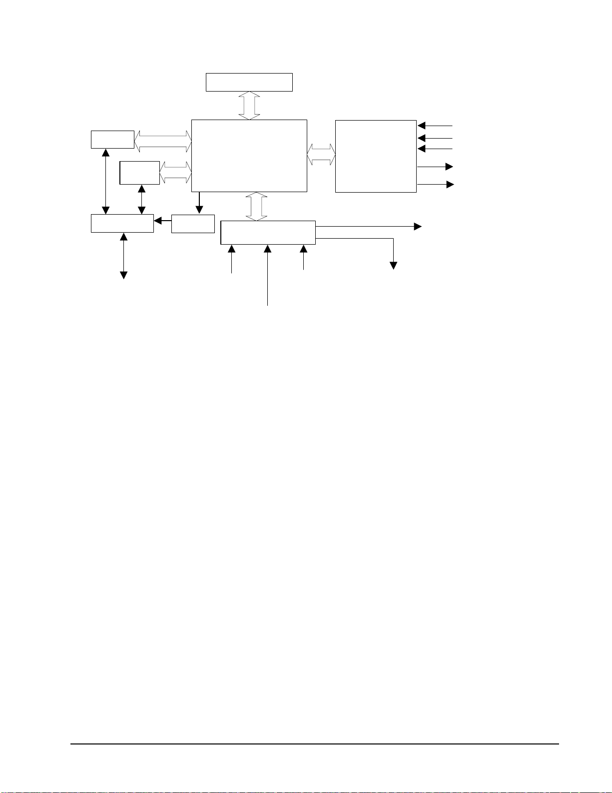
DMC-13X8 Functional Elements
The DMC-13X8 circuitry can be divided into the following functional groups as shown in Figure 1.1
and discussed below.
Chapter 1 Overview • 10 USER MANUAL
Page 11
2ND FIFO
Primary
FIFO
VME HOST
INTERRUPTS
WATCHDOG TIMER
68331
MICROCOMPUTER
WITH
2 Meg RAM
2 Meg FLASH EEPROM
I/O INTERFACE
HIGH-SPEED
MOTOR/ENCODER
INTERFACE
FOR
X,Y,Z,W
ISOLATED LIMITS AND
HOME INPUTS
MAIN ENCODERS
AUXILIARY ENCODERS
+/- 10 VOLT OUTPUT FOR
SERVO MOTORS
PULSE/DIRECTION OUTPUT
FOR STEP MOTORS
HIGH SPEED ENCODER
COMPARE OUTPUT
USER INTERFACE
8 UNCOMMITTED
ANALOG IN PUTS
HIGH-SPEED LATCH FOR EACH AXIS
8 PROGRAMMABLE,
OPTOISOLATED
INPUTS
8 PROGRAMMABLE
OUTPUTS
Figure 1.1 - DMC-13X8 Functional Elements
Microcomputer Section
The main processing unit of the controller is a specialized 32-bit Motorola 68331 Series
Microcomputer with 2M RAM and 2M Flash EEPROM. The RAM provides memory for variables,
array elements, and application programs. The flash EEPROM provides non-volatile storage of
variables, programs, and arrays. It also contains the firmware of the controller.
Motor Interface
Galil’s GL-1800 custom, sub-micron gate array performs quadrature decoding of each encoder at up to
12 MHz. For standard servo operation, the controller generates a +/-10 Volt analog signal (16 Bit
DAC). For sinusoidal commutation operation, the controller uses 2 DACs to generate 2 +/-10Volt
analog signals. For stepper motor operation the controller generates a step and direction signal.
Communication
The DMC-13X8 is an A16D08(O) 6U VME card. The communication interface with the VME host
contains a primary and secondary communication channel. The primary channel uses a bi-directional
FIFO (AM4701). The secondary channel is a 512 byte Polling FIFO (IDT7201) where data is placed
into the controller’s FIFO buffer. The DMC- 13 X 8 uses vectored hardware interrupts throug h t he
VME host.
General I/O
The controller provides interface circuitry for 8 bi-directional, optoisolated inputs, 8 TTL outputs, and
8 analog inputs with 12-Bit ADC (16-bit optional). The general inputs can also be used for triggering a
high-speed positional latch for each axis.
USER MANUAL Chapter 1 Overview • 11
Page 12
The DMC-13X8 also provides standard 64 extended I/O points. These TTL I/O points are software
configurable in banks of 8 points, and can be brought out directly on the IOM-1964 I/O module.
Each axis on the controller has 2 encoders, the main encoder and an auxiliary encoder. Each unused
auxiliary encoder provides 2 additional inputs available for general use (except when configured for
stepper motor operation).
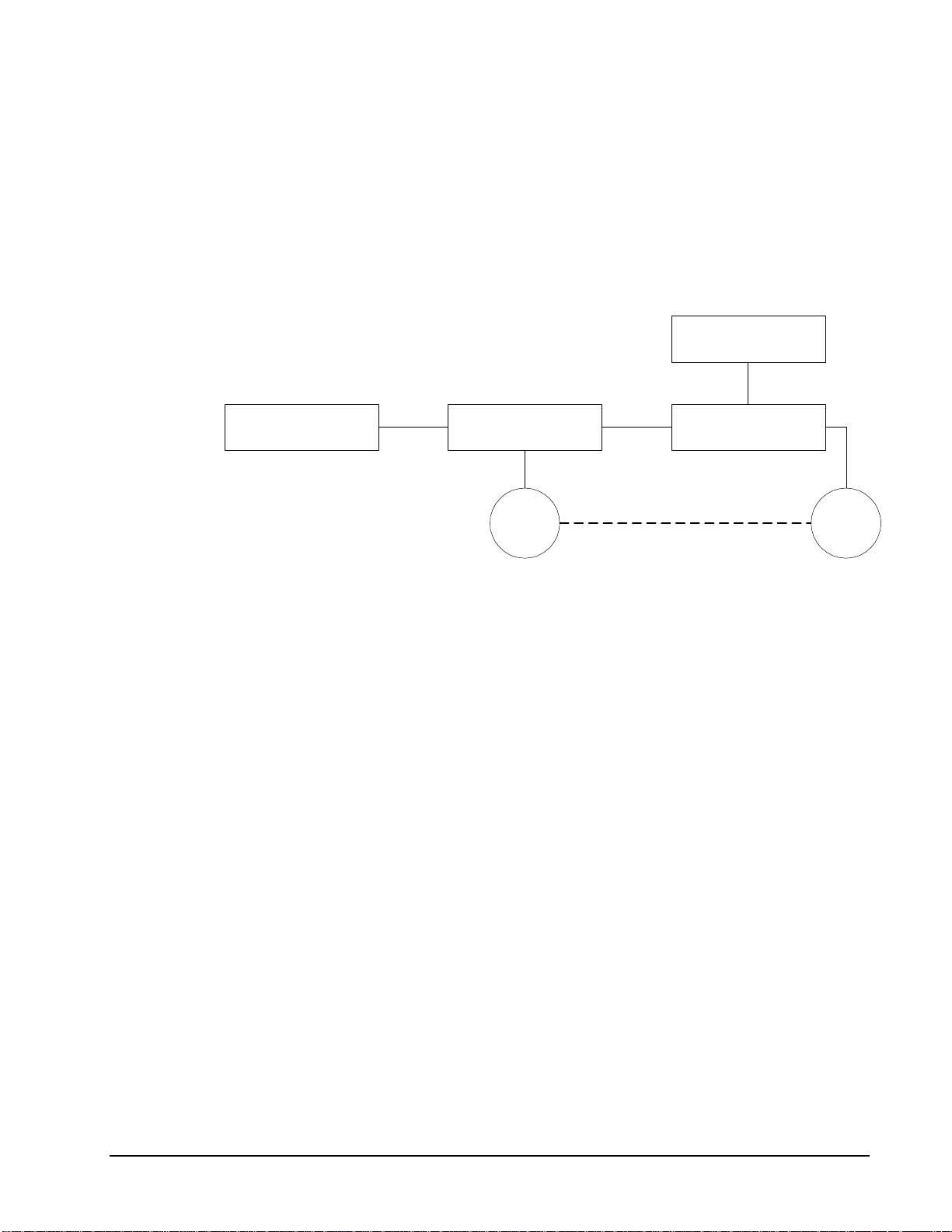
System Elements
As shown in Fig. 1.2, the DMC-13X8 is part of a motion control system which includes amplifiers,
motors, and encoders. These elements are described below.
Power Supply
Computer
Figure 1.2 - Elements of Servo systems
DMC-1700/1800
Controller
Encoder Motor
Driver
Motor
A motor converts current into torque which produces motion. Each axis of motion requires a motor
sized properly to move the load at the required speed and acceleration. (Galil's "Motion Component
Selector" software can help you with motor sizing). Contact Galil at 800-377-6329 if you would like
this product.
The motor may be a step or servo motor and can be brush-type or brushless, rotary or linear. For step
motors, the controller can operate full-step, half-step, or microstep drives. An encoder is not required
when step motors are used.
Amplifier (Driver)
For each axis, the power amplifier converts a +/-10 Volt signal from the controller into current to
drive the motor. For stepper motors, the amplifier converts step and direction signals into current.
The amplifier should be sized properly to meet the power requirements of the motor. For brushless
motors, an amplifier that provides electronic commutation is required or the controller must be
configured to provide sinusoidal commutation. The amplifiers may be either pulse-width-modulated
(PWM) or linear. They may also be configured for operation with or without a tachometer. For
current amplifiers, the amplifier gain should be set such that a 10 Volt command generates the
maximum required current. For example, if the motor peak current is 10A, the amplifier gain should
be 1 A/V. For velocity mode amplifiers, 10 Volts should run the motor at the maximum speed.
Chapter 1 Overview • 12 USER MANUAL
Page 13

Encoder
An encoder translates motion into electrical pulses which are fed back into the controller. The DMC13X8 accepts feedback from either a rotary or linear encoder. Typical encoders provide two channels in
quadrature, known as CHA and CHB. This type of encoder is known as a quadrature encoder.
Quadrature encoders may be either single-ended (CHA and CHB) or differential (CHA, CHA-, CHB,
CHB-). The controller decodes either type into quadrature states or four times the number of cycles.
Encoders may also have a third channel (or index) for synchronization.
The DMC-13X8 can also interface to encoders with pulse and direction signals.
There is no limit on encoder line density; however, the input frequency to the controller must not
exceed 3,000,000 full encoder cycles/second (12,000,000 quadrature counts/sec). For example, if the
encoder line density is 10,000 cycles per inch, the maximum speed is 300 inches/second. If higher
encoder frequency is required, please consult the factory.
The standard voltage level is TTL (zero to five volts), however, voltage levels up to 12 Volts are
acceptable. (If using differential signals, 12 Volts can be input directly to the DMC-13X8. Singleended 12 Volt signals require a bias voltage input to the complementary inputs).
The DMC-13X8 can accept analog feedback instead of an encoder for any axis. For more information
see the command AF in the command reference.
To interface with other types of position sensors such as resolvers or absolute encoders, Galil can
customize the controller and command set. Please contact Galil to talk to one of our applications
engineers about your particular system requirements.
Watch Dog Timer
The DMC-13X8 provides an internal watchdog timer which checks for proper microprocessor
operation. The timer toggles the Amplifier Enable Output (AEN), which can be used to switch the
amplifiers off in the event of a serious controller failure. The AEN output is normally high. During
power-up and if the microprocessor ceases to function properly, the AEN output will go low. The
error light for each axis will also turn on at this stage. A reset is required to restore the controller to
normal operation. Consult the factory for a Return Materials Authorization (RMA) Number if your
DMC-13X8 is damaged.
USER MANUAL Chapter 1 Overview • 13
Page 14

THIS PAGE LEFT BLANK INTENTIONALLY
Chapter 1 Overview • 14 USER MANUAL
Page 15
Chapter 2 Getting Started
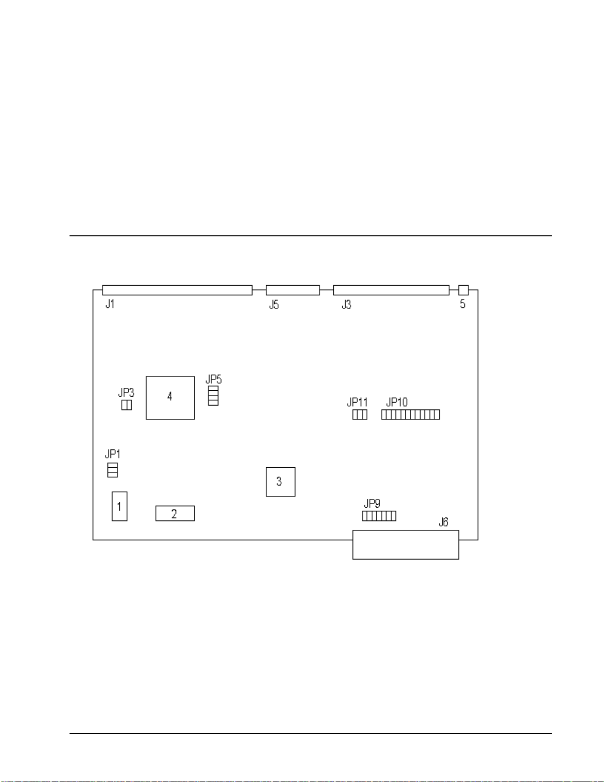
The DMC-13X8 Motion Controller
Figure 2-1 - Outline of the DMC-13X8
USER MANUAL Chapter 2 Getting Started • 15
Page 16

1 Flash EEPROM J6 VME Connector
2 RAM JP1 Master Reset & UPGRD jumpers
3 Motorola 68331 microprocessor JP3 INCOM & LSCOM jumpers. Used for
bypassing opto-isolation for the limit, home, and
abort switches and the digital inputs IN1 - IN8.
See section “Bypassing Opto-Isolation”, Chap3.
4 GL-1800 custom gate array JP5 Jumpers used for configuring stepper motor
operation on axes 1-4.
5 Error LED JP9 IRQ jumper. Interrupts may be set on IRQ 1–7.
J1 100-pin high density connector for axes 1-4.
(Part number Amp #2-178238-9)
J3 80 Pin high-density connector for 64
extended I/O points.
J5 26-pin header connector for the auxiliary
encoder cable. (Axes 1-4)
Note: Above schematics are for most current controller revision. For older revision boards, please refer to Appendix.
JP10 Address jumpers. The base address of the
controller is FFF0. Address jumpers A4-A15
may be set as offsets to that address
JP11 IAD1-IAD4 allows transfer of the IRQ between
the controller and host. This three bit binary
combination must be set equal to the IRQ line
chosen.
Elements You Need
Before you start, you must get all the necessary system elements. These include:
1. DMC-13X8, (1) 100-pin cable and (1) ICM-1900. Connection to the exten ded I/O can be
made through the IOM-1964 opto-isolation module. Using the IOM-1964 requires (1)
IOM-1964, (1) CB-50-100 and (1) 100 pin cable.
2. Servo motors with Optical Encoder (one per axis) or step motors.
3. Power Amplifiers.
4. Power Supply for Amplifiers.
5. VME host and user interface.
The motors may be servo (brush type or brushless) or steppers. The amplifiers should be suitable for
the motor and may be linear or pulse-width-modulated. An amplifier may have current feedback,
voltage feedback or velocity feedback.
Chapter 2 Getting Started • 16 USER MANUAL
For servo motors in current mode, the amplifiers should accept an analog signal in the +/-10 Volt range
as a command. The amplifier gain should be set such that a +10V command will generate the
maximum required current. For example, if the motor peak current is 10A, the amplifier gain should
be 1 A/V. For velocity mode amplifiers, a command signal of 10 Volts should run the motor at the
maximum required speed. Set the velocity gain so that an input signal of 10V, runs the motor at the
maximum required speed.
For step motors, the amplifiers should accept step and direction signals. For start-up of a step motor
system refer to Step 7c “Connecting Step Motors”.
Page 17

Installing the DMC-13X8
Installation of a complete, operational DMC-13X8 system consists of 8 steps.
Step 1. Determine overall motor configuration.
Step 2. Install Jumpers on the DMC-13X8.
Step 3. Install the DMC-13X8 in the PC.
Step 4. Establish communications with the Galil controller.
Step 5. Determine the Axes to be used for sinusoidal commutation.
Step 6. Make connections to amplifier and encoder.
Step 7a. Connect standard servo motors.
Step 7b. Connect sinusoidal commutation motors.
Step 7c. Connect step motors.
Step 8. Tune the servo system.
Step 1. Determine Overall Motor Configuration
Before setting up the motion control system, the user must determine the desired motor configuration.
The DMC-13X8 can control any combination of standard servo motors, sinusoidally commutated
brushless motors, and stepper motors. Other types of actuators, such as hydraulics can also be
controlled. Please consult Galil for more information.
The following configuration information is necessary to determine the proper motor configuration:
Standard Servo Motor Operation:
The DMC-13X8 has been setup by the factory for standard servo motor operation providing an analog
command signal of +/- 10V. No hardware or software configuration is required for standard servo
motor operation.
Sinusoidal Commutation:
Sinusoidal commutation is configured through a single software command, BA. This configuration
causes the controller to reconfigure the number of available control axes.
Each sinusoidally commutated motor requires two DAC's. In standard servo operation, the DMC13X8 has one DAC per axis. In order to have the additional DAC for sinusoidal commutation, the
controller must be designated as having one additional axis for each sinusoidal commutation axis. For
example, to control two standard servo axes and one axis of sinusoidal commutation, the controller
will require a total of four DAC's and the controller must be a DMC-1348.
Sinusoidal commutation is configured with the command, BA. For example, BAX sets the X axis to
be sinusoidally commutated. The second DAC for the sinusoidal signal will be the highest available
DAC on the controller. For example: Using a DMC-1348, the command BAX will configure the X
axis to be the main sinusoidal signal and the 'W' axis to be the second sinuso idal signal.
The BA command also reconfigures the controller to indicate that the controller has one less axis of
'standard' control for each axis of sinusoidal commutation. For example, if the command BAX is
given to a DMC-1348 controller, the controller will be re-configured to a DMC-1338 controller. By
definition, a DMC-1338 controls 3 axes: X,Y and Z. The 'W' axis is no longer available since the
output DAC is being used for sinusoi dal c om mutation.
Further instruction for sinusoidal commutation connections are discussed in Step 5.
USER MANUAL Chapter 2 Getting Started • 17
Page 18

Stepper Motor Operation:
To configure the DMC-13X8 for stepper motor operation, the controller requires a jumper for each
stepper motor and the command, MT, must be given. The installation of the stepper motor jumper is
discussed in the following section entitled "Installing Jumpers on the DMC-13X8". Further
instruction for stepper motor connections are disc usse d in St ep 7c.
Step 2. Install Jumpers on the DMC-13X8
Address Jumpers
The DMC-13X8 resides in the 16-bit short I/O space of the VME system. The base address of the
DMC-13X8 is set at FFF0. The address jumpers at JP10 are used to select the specific address for the
DMC-13X8 in the VME system. Placing a jumper on an address A4 through A15 makes that location
a 0.
For example, to set the controller address to FFE0, a jumper is placed on location A4.
Master Reset and Upgrade Jumpers
JP1 contains two jumpers, MRST and UPGRD. The MRST jumper is the Master Reset jumper. With
MRST connected, the controller will perform a master reset upon PC power up or upon the reset input
going low. Whenever the controller has a master reset, all programs, arrays, variables, and motion
control parameters stored in EEPROM will be ERASED.
The UPGRD jumper enables the user to unconditionally update the controller’s firmware. This jumper
is not necessary for firmware updates when the controller is operating normally, but may be necessary
in cases of corrupted EEPROM. EEPROM corruption should never occur, however, it is possible if
there is a power fault during a firmware update. If EEPROM corruption occurs, your controller may
not operate properly. In this case, install the UPGRD Jumper and use the update firmware function on
the Galil Terminal to re-load the system firmware.
Opto Isolation Jumpers
The inputs and limit switches are optoisolated. If you are not using an isolated supply, the internal
+5V supply from the PC may be used to power the optoisolators. This is done by installing jumpers on
JP3.
For each axis that will be used for stepper motor operation, the corresponding stepper mode (SM)
jumper must be connected. The stepper motor jumpers, labeled JP5, are located directly beside the
GL-1800 IC on the main board (see the diagram for the DMC-13X8). The individual jumpers are
labeled SMX, SMY, SMZ and SMW.
Stepper Motor Jumpers
Hardware IRQ (Interrupt) Jumpers
The DMC-13X8 controller supports vectored hardware interrupts. The jumper locations JP9 and JP11
are used to select the IRQ line which will interrupt the bus. IRQ1 through IRQ7 are available to the
user as hardware interrupts, and are set at location JP9. The second set of jumpers located at JP11 are
labeled IAD4, IAD2 and IAD1. The summation of these jumpers should be set equal to the IRQ
selected on JP9.
For example, suppose the VME host for a certain system requires a hardware interrupt on IRQ 5. A
jumper would therefore be placed at location JP9 on the pins labeled IRQ5. In addition, IAD4 and
IAD1, which add up to 5, will be jumpered at location JP11.
The vector and the conditions triggering the hardware interrupt on the DMC-13X8 are set through
software using the EI or the UI command. The DMC-13X8 will provide the hardware interrupt to the
Chapter 2 Getting Started • 18 USER MANUAL
Page 19

system upon the specified conditions. It is up to the user to supply an appropriate interrupt handling
routine for the VME host.
(Optional) Motor Off Jumpers
The state of the motor upon power up may be selected with the placement of a hardware jumper on the
controller. With a jumper installed at the OPT location, the controller will be powered up in the ‘motor
off’ state. The SH command will need to be issued in order for the motor to be enabled. With no
jumper installed, the controller will immediately enable the motor upon power up. The MO command
will need to be issued to turn the motor off.
The OPT jumper is always located on the same block of jumpers as the stepper motor jumpers (SM).
This feature is only available to newer revision controllers. Please consult Galil for adding this
functionality to older revision controllers.
Step 3. Install the DMC-13X8 in the VME Host
The DMC-13X8 is installed directly into the VME bus. The procedure is outlined below.
Step A. Make sure the VME host is in the power-off condition.
Step B. Insert DMC-13X8 card into a slot in the VME bus.
Step E. Attach 100-pin cable to your controller card. If you are using a Galil ICM-1900 or
AMP-19X0, this cable connects into the J2 connection on the interconnect module. If
you are not using a Galil interconnect module, you will need to appropriately terminate
the cable to your system components, see the appendix for cable pin outs. The auxiliary
encoder connections are accessed through the 36-pin high-density connector, which will
mate via the CB-36-25 to the ICM-1900.
Step 4. Establish Communication with the Galil controller
The customer will be required to provide a communication interface for the DMC-13X8 and their
specified host VME system. For development of the software interface, refer to Chapter 4 to find
information on the communication registers of the controller.
NOTE: It is highly recommended that communication be established with the controller prior to
applying any power to the amplifiers or other components.
Step 5. Determine the Axes to be Used for Sinusoidal Commutation
* This step is only required when the controller will be used to control a brushless motor(s) with
sinusoidal commutation.
The command, BA is used to select the axes of sinusoidal commutation. For example, BAXZ sets X
and Z as axes with sinusoidal commutation.
Notes on Configuring Sinusoidal Commutation:
The command, BA, reconfigures the controller such that it has one less axis of 'standard' control for
each axis of sinusoidal commutation. For example, if the command BAX is given to a DMC-1338
controller, the controller will be re-configured to be a DMC-1328 controller. In this case the highest
axis is no longer available except to be used for the 2
the highest axis on a controller can never be configured for sinusoidal commutation.
The first phase signal is the motor command signal. The second phase is derived from the highest
DAC on the controller. When more than one axis is configured for sinusoidal commutation, the
highest sinusoidal commutation axis will be assigned to the highest DAC and the lowest sinusoidal
commutation axis will be assigned to the lowest available DAC. Note the lowest axis is the X axis.
nd
phase of the sinusoidal commutation. Note that
USER MANUAL Chapter 2 Getting Started • 19
Page 20

Example: Sinusoidal Commutation Configuration using a DMC-1348
BAXZ
This command causes the controller to be reconfigured as a DMC-1328 controller. The X and Z axes
are configured for sinusoidal commutation. The first phase of the X axis will be the motor command
X signal. The second phase of the X axis will be Y signal. The first phase of the Z axis will be the
motor command Z signal. The second phase of the Z axis will be the motor command W signal.
Step 6. Make Connections to Amplifier and Encoder.
Once you have established communications between the software and the DMC-13X8, you are ready
to connect the rest of the motion control system. The motion control system typically consists of an
ICM-1900 Interface Module, an amplifier for each axis of motion, and a motor to transform the current
from the amplifier into torque for motion. Galil also offers the AMP-19X0 series Interface Modules
which are ICM-1900’s equipped with servo amplifiers for brush type DC motors.
If you are using an ICM-1900, connect the 100-pin high-density cable to the D MC-13X8 and to the
connector located on the AMP-19x0 or ICM-1900 board. The ICM-1900 provides screw terminals for
access to the connections described in the following discussion.
System connection procedures will depend on system components and motor types. Any combination
of motor types can be used with the DMC-13X8. If sinusoidal commutation is to be used, special
attention must be paid to the reconfiguration of axes.
Here are the first steps for connecting a motion control system:
Step A. Connect the motor to the amplifier with no connection to the controller. Consult the
amplifier documentation for instructions regard ing proper connections. Connect and
turn-on the amplifier power supply. If the amplifiers are operating properly, the motor
should stand still even when the amplifiers are powered up.
Step B. Connect the amplifier enable signal.
Before making any connections from the amplifier to the controller, you need to verify
that the ground level of the amplifier is either floating or at the same potential as earth.
WARNING: When the amplifier ground is not isolated from the power line or when it has a different potential
than that of the computer ground, serious damage may result to the computer controller and amplifier.
If you are not sure about the potential of the ground levels, connect the two ground
signals (amplifier ground and earth) by a 10 KΩ resistor and measure the voltage across
the resistor. Only if the voltage is zero, connect the two ground signals directly.
The amplifier enable signal is used by the controller to disable the motor. This signal is
labeled AMPENX for the X axis on the ICM-1900 and should be connected to the enable
signal on the amplifier. Note that many amplifiers designate this signal as the INHIBIT
signal. Use the command, MO, to disable the motor amplifiers - check to insure that the
motor amplifiers have been disabled (often this is indicated by an LED on the amplifier).
This signal changes under the following conditions: the watchdog timer activates, the
motor-off command, MO, is given, or the OE1 command (Enable Off-On-Error) is given
and the position error exceeds the error limit. As shown in Figure 3-3, AEN can be used
to disable the amplifier for these conditions.
The standard configuration of the AEN signal is TTL active high. In other words, the
AEN signal will be high when the controller expects the amplifier to be enabled . The
polarity and the amplitude can be changed if you are using the ICM-1900 interface board.
To change the polarity from active high (5 volts = enable, zero volts = disable) to active
low (zero volts = enable, 5 volts = disable), replace the 7407 IC with a 7406. Note that
many amplifiers designate the enable input as ‘inhibit’.
Chapter 2 Getting Started • 20 USER MANUAL
Page 21

To change the voltage level of the AEN signal, note the state of the resistor pack on the
ICM-1900. When Pin 1 is on the 5V mark, the output voltage is 0-5V. To change to 12
volts, pull the resistor pack and rotate it so that Pin 1 is on the 12 volt side. If you
remove the resistor pack, the output signal is an open collector, allowing the user to
connect an external supply with voltages up to 24V.
Step C. Connect the encoders
For stepper motor operation, an encoder is optional.
For servo motor operation, if you have a preferred definition of the forward and reverse
directions, make sure that the encoder wiring is consistent with that definition.
The DMC-13X8 accepts single-ended or differential encoder feedback with or without an
index pulse. If you are not using the AMP-19x0 or the ICM-1900 you will need to
consult the appendix for the encoder pinouts for connection to the motion controller. The
AMP-19x0 and the ICM-1900 can accept encoder feedback from a 10-pin ribbon cable or
individual signal leads. For a 10-pin ribbo n cable encoder, connect the cable to the
protected header connector labeled X ENCODER (repeat for each axis necessary). For
individual wires, simply match the leads from the encoder you are using to the encoder
feedback inputs on the interconnect board. The signal leads are labeled CHA (channel
A), CHB (channel B), and INDEX. For differential encoders, the complement signals are
labeled CHA-, CHB-, and INDEX-.
Note: When using pulse and direction encoders, the pulse signal is connected to CHA
and the direction signal is connected to CHB. The controller must be configured for
pulse and direction with the command CE. See the command summary for further
information on the command CE.
Step D. Verify proper encoder operation.
Start with the X encoder first. Once it is connected, turn the motor shaft and interrogate
the position with the instruction TPX <return>. The controller response will vary as the
motor is turned.
At this point, if TPX does not vary with encoder rotation, there are three possibilities:
1. The encoder connections are incorrect - check the wiring as necessary.
2. The encoder has failed - using an oscilloscope, observe the encoder signals. Verify
that both channels A and B have a peak magnitude between 5 and 12 volts. Note
that if only one encoder channel fails, the position reporting varies by one count
only. If the encoder failed, replace the encoder. If you cannot observe the encoder
signals, try a different encoder.
3. There is a hardware failure in the controller - connect the same encoder to a different
axis. If the problem disappears, you probably have a hardware failure. Consult the
factory for help.
Step E. Connect Hall Sensors if available.
Hall sensors are only used with sinusoidal commutation and are not necessary for proper
operation. The use of hall sensors allows the controller to automatically estimate the
commutation phase upon reset and also provides the controller the ability to set a more
precise commutation phase. Without hall sensors, the commutation phase must be
determined manually.
The hall effect sensors are connected to the digital inputs of the controller. These inputs
can be used with the general use inputs (bits 1-8), the auxiliary encoder inputs (bits 81-
96), or the extended I/O inputs of the DMC-13X8 controller (bits 17-80). Note: The
general use inputs are optoisolated and require a voltage connection at the INCOM point
- for more information regarding the digital inputs, see Chapter 3, Connecting H ardware.
USER MANUAL Chapter 2 Getting Started • 21
Page 22

Each set of sensors must use inputs that are in consecutive order. The input lines are
specified with the command, BI. For example, if the Hall sensors of the Z axis are
connected to inputs 6, 7 and 8, use the instruction:
BI ,, 6
or
BIZ = 6
Step 7a. Connect Standard Servo Motors
The following discussion applies to connecting the DMC-13X8 controller to standard servo motor
amplifiers:
The motor and the amplifier may be configured in the torque or the velocity mode. In the torque
mode, the amplifier gain should be such that a 10 Volt signal generates the maximum required current.
In the velocity mode, a command signal of 10 Volts should run the motor at the maximum required
speed.
Check the Polarity of the Feedback Loop
It is assumed that the motor and amplifier are connected together and that the encoder is operating
correctly (Step B). Before connecting the motor amplifiers to the controller, read the following
discussion on setting Error Limits and Torque Limits. Note that this discussion only uses the X axis as
an example.
Step A. Set the Error Limit as a Safety Precaution
Usually, there is uncertainty about the correct polarity of the feedback. The wrong
polarity causes the motor to run away from the starting position. Using a terminal
program, such as DMCTERM, the following parameters can be given to avoid system
damage:
Input the commands:
ER 2000 <CR> Sets error limit on the X axis to be 2000 encoder counts
OE 1 <CR> Disables X axis amplifier when excess position error exists
If the motor runs away and creates a position error of 2000 counts, the motor amplifier
will be disabled. Note: This function requires the AEN signal to be connected from the
controller to the amplifier.
Step B. Set Torque Limit as a Safety Precaution
To limit the maximum voltage signal to your amplifier, the DMC-13X8 controller has a
torque limit command, TL. This command sets the maximum voltage output of the
controller and can be used to avoid excessive torque or speed when initially setting up a
servo system.
When operating an amplifier in torque mode, the v
voltage output of the controller will be directly related to the torque output of the motor.
The user is responsible for determining this relationship using the documentation of the
motor and amplifier. The torque limit can be set to a value that will limit the motors
output torque.
When operating an amplifier in velocity or voltage mode, the voltage output of the
controller will be directly related to the velocity of the motor. The user is responsible for
determining this relationship using the documentation of the motor and amplifier. The
torque limit can be set to a value that will limit the speed of the motor.
Chapter 2 Getting Started • 22 USER MANUAL
Page 23

For example, the following command will limit the output of the controller to 1 volt on
the X axis:
TL 1 <CR>
Note: Once the correct polarity of the feedback loop has been determined, the torque limit
should, in general, be increased to the default value of 9.99. The servo will not operate
properly if the torque limit is below the normal operating range. See description of TL in
the command reference.
Step C. Enable Off-On-Error as a safety precaution. To limit the maximum distance the
motor will move from the commanded position, enable the Off-On-Error function using
the command , OE 1. If the motor runs away due to positive feedback or another
systematic problem the controller will disable the amplifier when the position error
exceeds the value set by the command, ER.
Step D. Disable motor with the command MO (Motor off).
Step E. Connect the Motor and issue SH
Once the parameters have been set, connect the analog motor command signal (ACMD)
to the amplifier input.
To test the polarity of the feedback, command a move with the instruction:
PR 1000 <CR> Position relative 1000 counts
BGX <CR> Begin motion on X axis
When the polarity of the feedback is wrong, the motor will attempt to run away. The
controller should disable the motor when the position error exceeds 2000 counts. If the
motor runs away, the polarity of the loop must be inverted.
Inverting the Loop Polarity
When the polarity of the feedback is incorrect, the user must invert the loop polarity and this may be
accomplished by several methods. If you are driving a brush-type DC motor, the simplest way is to
invert the two motor wires (typically red and black). For example, switch the M1 and M2 connections
going from your amplifier to the motor. When driving a brushless motor, the polarity reversal may be
done with the encoder. If you are using a single-ended encoder, interchange the signal CHA and CHB.
If, on the other hand, you are using a differential encoder, interchange only CHA+ and CHA-. The
loop polarity and encoder polarity can also be affected through software with the MT, and CE
commands. For more details on the MT command or the CE command, see the Command Reference
section.
Sometimes the feedback polarity is correct (the motor does not attempt to run away) but the direction
of motion is reversed with respect to the commanded motion. If this is the case, reverse the motor
leads AND the encoder signals.
If the motor moves in the required direction but stops short of the target, it is most likely due to
insufficient torque output from the motor command signal ACMD. This can be alleviated by reducing
system friction on the motors. The instruction:
TTX (CR) Tell torque on X
reports the level of the output signal. It will show a non-zero value that is below the friction level.
Once you have established that you have closed the loop with the correct polarity, you can move on to
the compensation phase (servo system tuning) to adjust the PID filter parameters, KP, KD and KI. It is
necessary to accurately tune your servo system to ensure fidelity of position and minimize motion
oscillation as described in the next section.
USER MANUAL Chapter 2 Getting Started • 23
Page 24
AUX encoder
input connector
DB25 female
AUX encoder
input connector
26 pin header
Reset Sw it ch Error LED
100 pin high density connector
AMP part # 2-178238-9
Filter
Chokes
J7
J51
J6
X
M1X
M2X
Y
LSCOM
INCOM
VCC
VCC
REV B
MADE IN USA
M1Y
M2Y
ICM/ AMP-1900
GALIL MOTION CONTROL
GND
EARTH
GND
VAMP
VAMP
Z
W
M1W
M1Z
M2Z
M2W
+
+
DC Power Supply
-
Encoder
DC Servo Motor
-
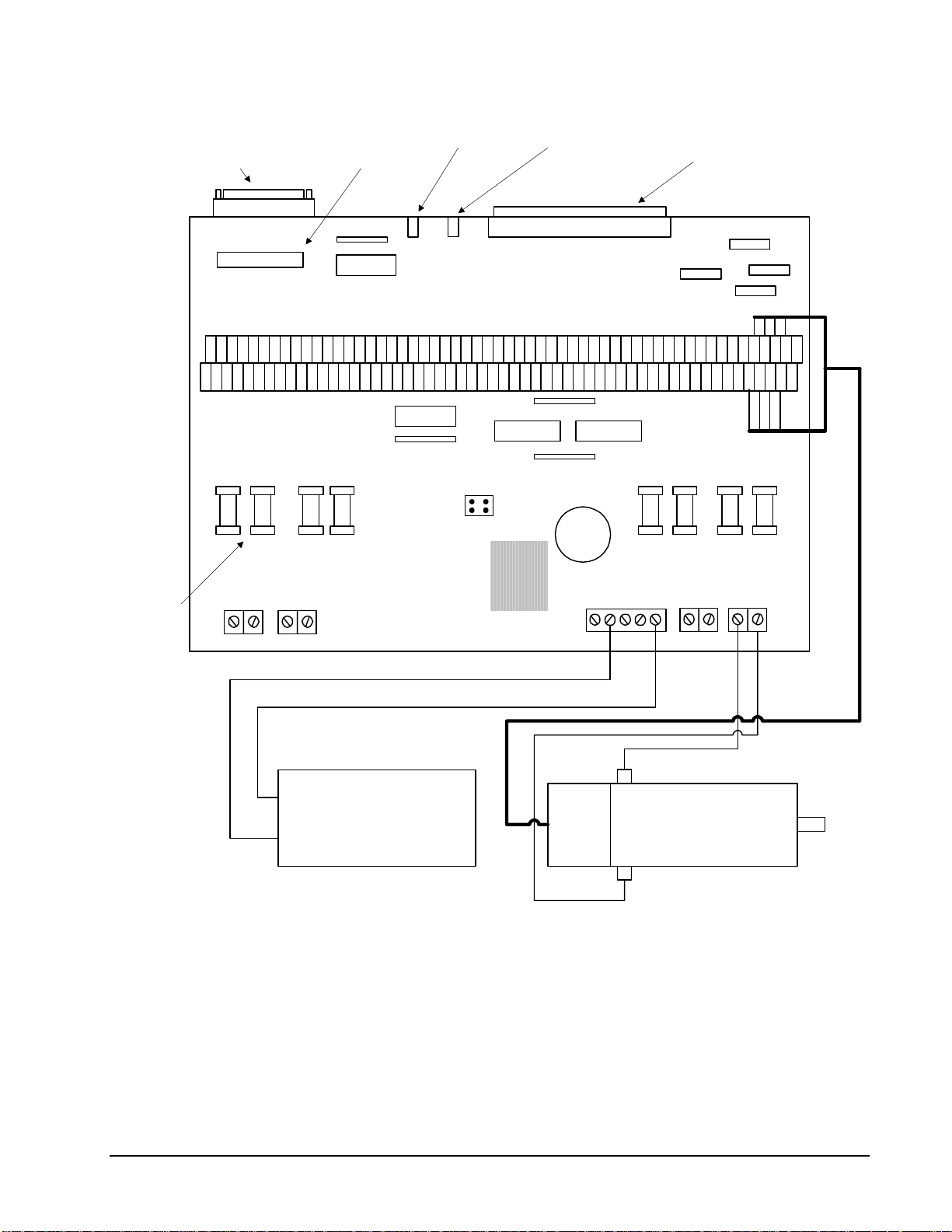
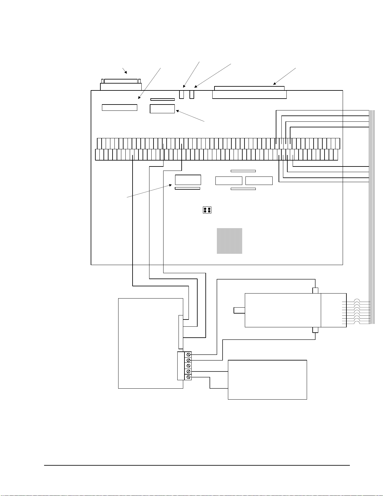
Figure 2-2 - System Connections with the AMP-1900 Amplifier. Note: this figure shows a Galil Motor and
Encoder which uses a flat ribbon cable for connection to the AMP-1900 unit.
Chapter 2 Getting Started • 24 USER MANUAL
Page 25
AUX encoder
input connector
DB25 female
AUX encoder
input connector
26 pin header
Rese t Swi t ch
Error LED
100 pin high density connector
AMP part # 2-178238-9
J7
J51
Amp enable
buffer circuit
RP2
ADG202
U1
U6RP1
7407
GND
MOCMDX
AMPENX
REV D
ICM/ AM P -1900
GALIL MOTION CONTROL
J6
Motor Command
buffer circuit
LSCOM
INCOM
VCC
VCC
MADE IN USA
-MAX
-MBX
-INX
+5 VDC
GND
+INX
+MBX
+MAX
Encoder Wire Connections
Encoder: ICM-1900:
Channel A+ +MAX
Channel A- -MAX
Channel B+ +MBX
Channel B- -MBX
Index Channel + +INX
Index Channel - -INX
+
Encoder
DC Brush
Signal Gnd 2
BRUSH-TYPE
PWM SERVO
AMPLIFIER
MSA 12-80
+Ref In 4
Inhibit 11
Motor + 1
Motor - 2
Power Gnd 3
Power Gnd 4
High Volt 5
+
DC Power Supply
-
Figure 2-3 System Connections with a separate amplifier (MSA 12-80). This diagram shows the connections for a
standard DC Servo Motor and encoder
USER MANUAL Chapter 2 Getting Started • 25
Serv o Motor
-
Page 26

Step 7b. Connect Sinusoidal Commutation Motors
When using sinusoidal commutation, the parameters for the commutation must be determined
and saved in the controllers non-volatile memory. The servo can then be tuned as
described in Step 8.
Step A. Disable the motor amplifier
Use the command, MO, to disable the motor amplifiers. For example, MOX will turn the
X axis motor off.
Step B. Connect the motor amplifier to the controller.
The sinusoidal commutation amplifier requires 2 signals, usually denoted as Phase A &
Phase B. These inputs should be connected to the two sinusoidal signals generated by the
controller. The first signal is the axis specified with the command, BA (Step 5). The
second signal is associated with the highest analog command signal available on the
controller - note that this axis was made unavailable for standard servo operation by the
command BA.
When more than one axis is configured for sinusoidal commutation, the controller will
assign the second phase to the command output which has been made available through
the axes reconfiguration. The 2
be the highest command output and the 2
axis will be the lowest command output.
It is not necessary to be concerned with cross-wiring the 1
is incorrect, the setup procedure will alert the user (Step D).
nd
phase of the highest sinusoidal commutation axis will
nd
phase of the lowest sinusoidal commutation
st
and 2nd signals. If this wiring
Example: Sinusoidal Commutation Configuration using a
DMC-1348
BAXZ
This command causes the controller to be reconfigu red as a DMC-13X8 controller. The
X and Z axes are configured for sinusoidal commutation. The first phase of the X axis
will be the motor command X signal. The second phase of the X axis will be the motor
command the motor command Y signal. The first phase of the Z axis will be the motor
command Z signal. The second phase of the Z axis will be the motor command W signal.
Step C. Specify the Size of the Magnetic Cycle.
Use the command, BM, to specify the size of the brushless motors magnetic cycle in
encoder counts. For example, if the X axis is a linear motor where the magnetic cycle
length is 62 mm, and the encoder resolution is 1 micron, the cycle equals 62,000 counts.
This can be commanded with the command.
BM 62000
On the other hand, if the Z axis is a rotary motor with 4000 counts per revolution and 3
magnetic cycles per revolution (three pole pairs) the command is
BM,, 1333.333
Step D. Test the Polarity of the DACs and Hall Sensor Configuration.
Use the brushless motor setup command, BS, to test the polarity of the output DACs.
This command applies a certain voltage, V, to each phase for some time T, and checks to
see if the motion is in the correct direction.
The user must specify the value for V and T. For example, the command
BSX = 2,700
Chapter 2 Getting Started • 26 USER MANUAL
Page 27

will test the X axis with a voltage of 2 volts, applying it for 700 millisecond for each
phase. In response, this test indicates whether the DAC wiring is correct and will
indicate an approximate value of BM. If the wiring is correct, the approximate value for
BM will agree with the value used in the previous step.
Note: In order to properly conduct the brushless setup, the motor must be allowed to
move a minimum of one magnetic cycle in both directions.
Note: When using Galil Windows software, the timeout must be set to a minimum of 10
seconds (time-out = 10000) when executing the BS command. This allows the software
to retrieve all messages returned from the controller.
If Hall Sensors are Available:
Since the Hall sensors are connected randomly, it is very likely that they are wired in the
incorrect order. The brushless setup command indicates the correct wiring of the Hall
sensors. The hall sensor wires should be re-configured to reflect the results of this test.
The setup command also reports the position offset of the hall transition point and the
zero phase of the motor commutation. The zero transition of the Hall sensors typically
occur at 0°, 30° or 90° of the phase commutation. It is necessary to inform the
controller about the offset of the Hall sensor and this is done with the instruction, BB.
Step E. Save Brushless Motor Configuration
It is very important to save the brushless motor configuration in non-volatile memory.
After the motor wiring and setup parameters have been properly configured, the burn
command, BN, should be given.
If Hall Sensors are Not Available:
Without hall sensors, the controller will not be able to estimate the commutation phase of
the brushless motor. In this case, the controller could become unstable until the
commutation phase has been set using the BZ command (see next step). It is highly
recommended that the motor off command be give n before executing the BN command.
In this case, the motor will be disabled upon power up or reset and the commutation
phase can be set before enabling the motor.
Step F. Set Zero Commutation Phase
When an axis has been defined as sinusoidally commutated, the controller must have an
estimate for commutation phase. When hall sensors are used, the controller automatically
estimates this value upon reset of the controller. If no hall sensors are used, the controller
will not be able to make this estimate and the commutation phase must be set before
enabling the motor.
If Hall Sensors are Not Available:
To initialize the commutation without Hall effect sensor use the command, BZ. This
function drives the motor to a position where the commutation phase is zero, and sets the
phase to zero.
The BZ command argument is a real number which represents the voltage to be applied
to the amplifier during the initialization. When the voltage is specified by a positive
number, the initialization process ends up in the motor off (MO) state. A negative
number causes the process to end in the Servo Here (SH) state.
Warning: This command must move the motor to find the zero commutation phase.
This movement is instantaneous and will cause the system to jerk. Larger applied
voltages will cause more severe motor jerk. The applied voltage will typically be
sufficient for proper operation of the BZ command. For systems with significant friction,
USER MANUAL Chapter 2 Getting Started • 27
Page 28

this voltage may need to be increased and for systems with very small motors, this value
should be decreased.
For example,
BZ -2
will drive the X axis to zero, using a 2V signal. The controller will then leave the motor
enabled. For systems that have external forces working against the motor, such as
gravity, the BZ argument must provide a torque 10x the external force. If the torque is
not sufficient, the commutation zero may not be accurate.
If Hall Sensors are Available:
The estimated value of the commutation phase is good to within 30°. This estimate can
be used to drive the motor but a more accurate estimate is needed for efficient motor
operation. There are 3 possible methods for commutation phase initialization:
Method 1. Use the BZ command as described above.
Method 2. Drive the motor close to commutation phase of zero and then use BZ
command. This method decreases the amount of system jerk by moving the motor close
to zero commutation phase before executing the BZ command. The controller makes an
estimate for the number of encoder counts between the current position and the position
of zero commutation phase. This value is stored in the operand _BZx. Using this
operand the controller can be commanded to move the motor. The BZ command is then
issued as described above. For example, to initialize the X axis motor upon power or
reset, the following commands may be given:
SHX ;Enable X axis motor
PRX=-1*(_BZX) ;Move X motor close to zero commutation phase
BGX ;Begin motion on X axis
AMX ;Wait for motion to complete on X axis
BZX=-1 ;Drive motor to commutation phase zero and leave
;motor on
Method 3. Use the command, BC. This command uses the hall transitions to determine
the commutation phase. Ideally, the hall sensor transitions will be separated by exactly
60° and any deviation from 60° will affect the accuracy of this method. If the hall
sensors are accurate, this method is recommended. The BC command monitors the hall
sensors during a move and monitors the Hall sensors for a transition point. When that
occurs, the controller computes the commutation phase and sets it. For example, to
initialize the X axis motor upon power or reset, the following commands may be given:
SHX ;Enable X axis motor
BCX ;Enable the brushless calibration command
PRX=50000 ;Command a relative position movement on X axis
BGX ;Begin motion on X axis. When the hall sensors
detect a phase transition, the commutation phase is re-set.
Chapter 2 Getting Started • 28 USER MANUAL
Page 29

Step 7C. Connect Step Motors
In Stepper Motor operation, the pulse output signal has a 50% duty cycle. Step motors operate open
loop and do not require encoder feedback. When a stepper is used, the auxiliary encoder for the
corresponding axis is unavailable for an external connection. If an encoder is used for position
feedback, connect the encoder to the main encoder input corresponding to that axis. The commanded
position of the stepper can be interrogated with RP o r DE. The encod er position can b e interrogated
with TP.
The frequency of the step motor pulses can be smoothed with the filter parameter, KS. The KS
parameter has a range between 0.5 and 8, where 8 implies the largest amount of smoothing. See
Command Reference regarding KS.
The DMC-13X8 profiler commands the step motor amplifier. All DMC-13X8 motion commands
apply such as PR, PA, VP, CR and JG. The acceleration, deceleration, slew speed and smoothing are
also used. Since step motors run open-loop, the PID filter does not function and the position error is
not generated.
To connect step motors with the DMC-13X8 you must follow this proc edure:
Step A. Install SM jumpers
Each axis of the DMC-13X8 that will operate a stepper motor must hav e the
corresponding stepper motor jumper installed. For a discussion of SM jumpers, see
section “Step 2. Install Jumpers on the DMC-13X8”.
Step B. Connect step and direction signals
For each axis of stepper control, connect the step and direction signals from the controller
to respective signals on your step motor amplifier. (These signals are labeled PULSX
and DIRX for the X-axis on the ICM-1900). Consult the documentation for your step
motor amplifier.
Step C. Configure DMC-13X8 for motor type using MT command. You can configure the
DMC-13X8 for active high or active low pulses. Use the command MT 2 for active high
step motor pulses and MT -2 for active low step motor pulses. See description of the MT
command in the Command Reference.
Step 8. Tune the Servo System
The final step for setting up the motion control system is adjusting the tuning parameters for optimal
performance of the servo motors (standard or sinusoidal commutation). The system compensation
provides fast and accurate response and the following presentation suggests a simple and easy way for
compensation.
The filter has three parameters: the damping, KD; the proportional gain, KP; and the integrator, KI.
The parameters should be selected in this order.
To start, set the integrator to zero with the instruction
KI 0 (CR) Integrator gain
and set the proportional gain to a low value, such as
KP 1 (CR) Proportional gain
KD 100 (CR) Derivative gain
For more damping, you can increase KD (maximum is 4095). Increase gradually and stop after the
motor vibrates. A vibration is noticed by audible sound or by interrogation. If you send the command
USER MANUAL Chapter 2 Getting Started • 29
Page 30

TE X (CR) Tell error
a few times, and get varying responses, especially with reversing polarity, it indicates system vibration.
When this happens, simply reduce KD.
Next you need to increase the value of KP gradually (maximum allowed is 1023). You can monitor the
improvement in the response with the Tell Error instruction
KP 10 (CR) Proportion gain
TE X (CR) Tell error
As the proportional gain is increased, the error decreases.
Again, the system may vibrate if the gain is too high. In this case, reduce KP. Typically, KP should
not be greater than KD/4. (Only when the amplifier is configured in the current mode).
Finally, to select KI, start with zero value and increase it gradually. The integrator eliminates the
position error, resulting in improved accuracy. Therefore, the response to the instruction
TE X (CR)
becomes zero. As KI is increased, its effect is amplified and it may lead to vibrations. If this occurs,
simply reduce KI. Repeat tuning for the Y, Z and W axes.
For a more detailed description of the operation of the PID filter and/or servo system theory, see
Chapter 10 - Theory of Operation.
Design Examples
Here are a few examples for tuning and using your controller. These examples have remarks next to
each command - these remarks must not be included in the actual program.
Example 1 - System Set-up
This example assigns the system filter parameters, error limits and enables the automatic error shut-off.
Instruction Interpretation
KP10,10,10,10 Set gains for a,b,c,d (or X,Y,Z,W axes)
KP*=10 Alternate method for setting gain on all axes
KPX=10 Alternate method for setting X (or A) axis gain
KPA=10 Alternate method for setting A (or X) axis gain
KP, 20 Set Y axis gain only
Instruction Interpretation
OE 1,1,1,1 Enable automatic Off on Error function for all axes
ER*=1000 Set error limit for all axes to 1000 counts
KP10,10,10,10 Set gains for a,b,c and d axes
KP*=10 Alternate method for setting gain on all axes
KPX=10 Alternate method for setting X (or A) axis gain
KPA=10 Alternate method for setting A (or X) axis gain
KP,,10 Set Z axis gain only
KPZ=10 Alternate method for setting Z axis gain
Chapter 2 Getting Started • 30 USER MANUAL
Page 31

KPD=10 Alternate method for setting D axis gain
Example 2 - Profiled Move
Objective: Rotate the X axis a distance of 10,000 counts at a slew speed of 20,000 counts/sec and an
acceleration and deceleration rates of 100,000 counts/s2. In this example, the motor turns and stops:
Instruction Interpretation
PR 10000 Distance
SP 20000 Speed
DC 100000 Deceleration
AC 100000 Acceleration
BG X Start Motion
Example 3 - Multiple Axes
Objective: Move the four axes independently.
Instruction Interpretation
PR 500,1000,600,-400 Distances of X,Y,Z,W
SP 10000,12000,20000,10000 Slew speeds of X,Y,Z,W
AC 100000,10000,100000,100000 Accelerations of X,Y,Z,W
DC 80000,40000,30000,50000 Decelerations of X,Y,Z,W
BG XZ Start X and Z motion
BG YW Start Y and W motion
Example 4 - Independent Moves
The motion parameters may be specified independently as illustrated below.
Instruction Interpretation
PR ,300,-600 Distances of Y and Z
SP ,2000 Slew speed of Y
DC ,80000 Deceleration of Y
AC, 100000 Acceleration of Y
SP ,,40000 Slew speed of Z
AC ,,100000 Acceleration of Z
DC ,,150000 Deceleration of Z
BG Z Start Z motion
BG Y Start Y motion
Example 5 - Position Interrogation
The position of the four axes may be interrogated with the instruction, TP.
Instruction Interpretation
TP Tell position all four axes
TP X Tell position - X axis only
USER MANUAL Chapter 2 Getting Started • 31
Page 32

TP Y Tell position - Y axis only
TP Z Tell position - Z axis only
TP W Tell position - W axis only
The position error, which is the difference between the commanded position and the actual position
can be interrogated with the instruction TE.
Instruction Interpretation
TE Tell error - all axes
TE X Tell error - X axis only
TE Y Tell error - Y axis only
TE Z Tell error - Z axis only
TE W Tell error - W axis only
Example 6 - Absolute Position
Objective: Command motion by specifying the absolute position.
Instruction Interpretation
DP 0,2000 Define the current positions of X,Y as 0 and 2000
PA 7000,4000 Sets the desired absolute positions
BG X Start X motion
BG Y Start Y motion
After both motions are complete, the X and Y axes can be command back to zero:
PA 0,0 Move to 0,0
BG XY Start both motions
Example 7 - Velocity Control
Objective: Drive the X and Y motors at specified speeds.
Instruction Interpretation
JG 10000,-20000 Set Jog Speeds and Directions
AC 100000, 40000 Set accelerations
DC 50000,50000 Set decelerations
BG XY Start motion
after a few seconds, command:
JG -40000 New X speed and Direction
TV X Returns X speed
and then
JG ,20000 New Y speed
TV Y Returns Y speed
These cause velocity changes including direction reversal. The motion can be stopped with the
instruction
ST Stop
Chapter 2 Getting Started • 32 USER MANUAL
Page 33

Example 8 - Operation Under Torque Limit
The magnitude of the motor command may be limited independently by the instruction TL.
Instruction Interpretation
TL 0.2 Set output limit of X axis to 0.2 volts
JG 10000 Set X speed
BG X Start X motion
In this example, the X motor will probably not move since the output signal will not be sufficient to
overcome the friction. If the motion starts, it can be stopped easily by a touch of a finger.
Increase the torque level gradually by instructions such as
Instruction Interpretation
TL 1.0 Increase torque limit to 1 volt.
TL 9.98 Increase torque limit to maximum, 9.98 Volts.
The maximum level of 9.998 volts provides the full output torque.
Example 9 - Interrogation
The values of the parameters may be interrogated. Some examples …
Instruction Interpretation
KP ? Return gain of X axis.
KP ,,? Return gain of Z axis.
KP ?,?,?,? Return gains of all axes.
Many other parameters such as KI, KD, FA, can also be interrogated. The command reference denotes
all commands which can be interrogated.
Example 10 - Operation in the Buffer Mode
The instructions may be buffered before execution as shown below.
Instruction Interpretation
PR 600000 Distance
SP 10000 Speed
WT 10000 Wait 10000 milliseconds before reading the next instruction
BG X Start the motion
Example 11 - Using the On-Board Editor
Motion programs may be edited and stored in the controller’s on-board memory. When the command,
ED is given from communications software, the controller’s editor will be started.
The instruction
ED Edit mode
moves the operation to the editor mode where the program may be written and edited. The ed itor
provides the line number. For example, in response to the first ED command, the first line is zero.
Line # Instruction Interpretation
000 #A Define label
001 PR 700 Distance
002 SP 2000 Speed
USER MANUAL Chapter 2 Getting Started • 33
Page 34

003 BGX Start X motion
004 EN End program
To exit the editor mode, input <cntrl>Q. The program may be executed with the command.
XQ #A Start the program running
Example 12 - Motion Programs with Loops
Motion programs may include conditional jumps as shown below.
Instruction Interpretation
#A Label
DP 0 Define current position as zero
V1=1000 Set initial value of V1
#Loop Label for loop
PA V1 Move X motor V1 counts
BG X Start X motion
AM X After X motion is complete
WT 500 Wait 500 ms
TP X Tell position X
V1=V1+1000 Increase the value of V1
JP #Loop,V1<10001 Repeat if V1<10001
EN End
After the above program is entered, quit the Editor Mode, <cntrl>Q. To start the motion, command:
XQ #A Execute Program #A
Example 13 - Motion Programs with Trippoints
The motion programs may include trippoints as shown below.
Instruction Interpretation
#B Label
DP 0,0 Define initial positions
PR 30000,60000 Set targets
SP 5000,5000 Set speeds
BGX Start X motion
AD 4000 Wait until X moved 4000
BGY Start Y motion
AP 6000 Wait until position X=6000
SP 2000,50000 Change speeds
AP ,50000 Wait until position Y=50000
SP ,10000 Change speed of Y
EN End program
To start the program, command:
XQ #B Execute Program #B
Chapter 2 Getting Started • 34 USER MANUAL
Page 35

Example 14 - Control Variables
Objective: To show how control variables may be utilized.
Instruction Interpretation
#A;DP0 Label; Define current position as zero
PR 4000 Initial position
SP 2000 Set speed
BGX Move X
AMX Wait until move is complete
WT 500 Wait 500 ms
#B
V1 = _TPX Determine distance to zero
PR -V1/2 Command X move 1/2 the distance
BGX Start X motion
AMX After X moved
WT 500 Wait 500 ms
V1= Report the value of V1
JP #C, V1=0 Exit if position=0
JP #B Repeat otherwise
#C Label #C
EN End of Program
To start the program, command
XQ #A Execute Program #A
This program moves X to an initial position of 1000 and returns it to zero on increments of half the
distance. Note, _TPX is an internal variable which returns the value of the X position. Internal
variables may be created by preceding a DMC-13X8 instruction with an underscore, _.
Example 15 - Linear Interpolation
Objective: Move X,Y,Z motors distance of 7000,3000,6000, respectively, along linear trajectory.
Namely, motors start and stop together.
Instruction Interpretation
LM XYZ Specify linear interpolation axes
LI 7000,3000,6000 Relative distances for linear interpolation
LE Linear End
VS 6000 Vector speed
VA 20000 Vector acceleration
VD 20000 Vector deceleration
BGS Start motion
Example 16 - Circular Interpolation
Objective: Move the XY axes in circular mode to form the path shown on Fig. 2-4. Note that the
vector motion starts at a local position (0,0) which is defined at the beginning of any vector motion
sequence. See application programming for further i nf ormation.
USER MANUAL Chapter 2 Getting Started • 35
Page 36

Instruction Interpretation
VM XY Select XY axes for circular interpolation
VP –4000,0 Linear segment
CR 2000,270,-180 Circular segment
VP 0,4000 Linear segment
CR 2000,90,-180 Circular segment
VS 1000 Vector speed
VA 50000 Vector acceleration
VD 50000 Vector deceleration
VE End vector sequence
BGS Start motion
Y
(0,4000)(-4000,4000)
R=2000
(-4000,0)
Figure 2-4 Motion Path for Example 16
(0,0) local zero
X
Chapter 2 Getting Started • 36 USER MANUAL
Page 37

Chapter 3 Connecting Hardware
Overview
The DMC-13X8 provides optoisolated digital inputs for forward limit, reverse limit, home, and
abort signals. The controller also has 8 optoisolated, uncommitted inputs (for general use) as well
as 8 TTL outputs and 8 analog inputs configured for voltages between +/- 10 volts.
The DMC-13X8 also have an additional 64 configurable TTL I/O which can be connected to the IOM-
1964 optoisolation module or to OPTO-22 I/O racks. Configuration information for the extended I/O
may be found in the appendix.
This chapter describes the inputs and outputs and their proper connection.
If you plan to use the auxiliary encoder feature of the DMC-13X8, you must also order and connect the
36 pin high-density cable. This cable connects from the auxiliary encoder connector on the DMC13X8 to either the ICM-1900 via the CB-36-25 or to the ICM-2908.
Using Optoisolated Inputs
Limit Switch Input
The forward limit switch (FLSx) inhibits motion in the forward direction immediately upon activation
of the switch. The reverse limit switch (RLSx) inhibits motion in the reverse direction immediately
upon activation of the switch. If a limit switch is activated during motion, the controller will make a
decelerated stop using the deceleration rate previously set with the DC command. The motor will
remain on (in a servo state) after the limit switch has been activated and will hold motor position.
When a forward or reverse limit switch is activated, the current application program that is running
will be interrupted and the controller will automatically jump to the #LIMSWI subroutine if one exists.
This is a subroutine which the user can include in any motion control program and is usefu l for
executing specific instructions upon activation of a limit switch. Automatic Subroutines are discussed
in Chapter 6.
After a limit switch has been activated, further motion in the direction of the limit switch will not be
possible until the logic state of the switch returns back to an inactive state. This usually involves
physically opening the tripped switch. Any attempt at further motion before the logic state has been
reset will result in the following error: “022 - Begin not possible due to limit switch” error.
The operands, _LFx and _LRx, contain the state of the forward and reverse limit switches, respectively
(x represents the axis, X,Y,Z,W etc.). The value of the operand is either a ‘0’ or ‘1’ corresponding to
the logic state of the limit switch. Using a terminal program, the state of a limit switch can be printed
to the screen with the command, MG _LFx or MG _LFx. This prints the value of the limit switch
operands for the 'x' axis. The logic state of the limit switches can also be interrogated with the TS
command. For more details on TS see the Command Reference.
USER MANUAL Chapter 3 Connecting Hardware • 37
Page 38

Home Switch Input
Homing inputs are designed to provide mechanical reference points for a motion control application.
A transition in the state of a Home input alerts the controller that a particular reference point has been
reached by a moving part in the motion control system. A reference point can be a point in space or an
encoder index pulse.
The Home input detects any transition in the state of the switch and toggles between logic states 0 and
1 at every transition. A transition in the logic state of the Home input will cause the controller to
execute a homing routine specified by the user.
There are three homing routines supported by the DMC-13X8 : Find Edge (FE), Find Index (FI), and
Standard Home (HM).
The Find Edge routine is initiated by the command sequence: FEX <return>, BGX <return>. The Find
Edge routine will cause the motor to accelerate, then slew at constant speed until a transition is
detected in the logic state of the Home input. The direction of the FE motion is dependent on the state
of the home switch. High level causes forward motion. The motor will then decelerate to a stop. The
acceleration rate, deceleration rate and slew speed are specified by the user, prior to the movement,
using the commands AC, DC, and SP. It is recommended that a high deceleration value be used so the
motor will decelerate rapidly after sensing the Home switch.
The Find Index routine is initiated by the command sequence: FIX <return>, BGX <return>. Find
Index will cause the motor to accelerate to the user-defined slew speed (SP) at a rate specified by the
user with the AC command and slew until the controller senses a change in the index pulse signal fro m
low to high. The motor then decelerates to a stop at the rate previously specified by the user with the
DC command. Although Find Index is an option for homing, it is not dependent upon a transition in
the logic state of the Home input, but instead is dependent upon a transition in the level of the index
pulse signal.
The Standard Homing routine is initiated by the sequence of commands HMX <return>, BGX
<return>. Standard Homing is a combination of Find Edge and Find Index homing. Initiating the
standard homing routine will cause the motor to slew until a transition is detected in the logic state of
the Home input. The motor will accelerate at the rate specified by the command, AC, up to the slew
speed. After detecting the transition in the logic state on the Home Input, the motor will decelerate to
a stop at the rate specified by the command, DC. After the motor has decelerated to a stop, it switches
direction and approaches the transition point at the speed of 256 counts/sec. When the logic state
changes again, the motor moves forward (in the direction of increasing encoder count) at the same
speed, until the controller senses the index pulse. After detection, it decelerates to a stop and defines
this position as 0. The logic state of the Home input can be interrogated with the command MG
_HMX. This command returns a 0 or 1 if the logic state is low or high, respectively. The state of the
Home input can also be interrogated indirectly with the TS command.
For examples and further information about Homing, see command HM, FI, FE of the Command
Reference and the section entitled ‘Homing’ in the Programming Motion Section of this manual.
Abort Input
The function of the Abort input is to immediately stop the controller upon transition of the logic state.
NOTE: The response of the abort input is significantly different from the response of an activated
limit switch. When the abort input is activated, the controller stops generating motion commands
immediately, whereas the limit switch response causes the controller to make a decelerated stop.
NOTE: The effect of an Abort input is dependent on the state of the off-on-error function for each
axis. If the Off-On-Error function is en abled for any given axis, the motor for that axis will be turned
off when the abort signal is generated. This could cause the motor to ‘coast’ to a stop since it is no
longer under servo control. If the Off-On-Error function is disabled, the motor will decelerate to a stop
as fast as mechanically possible and the motor will remain in a servo state.
Chapter 3 Connecting Hardware • 38 USER MANUAL
Page 39

All motion programs that are currently running are terminated when a transition in the Abort input is
detected. For information on setting the Off-On-Error function, see the Command Reference, OE.
Uncommitted Digital Inputs
The DMC-13X8 has 8 opto-isolated inputs. These inputs can be read individually using the function @
IN[x] where x specifies the input number (1 thru 8). These inputs are uncommitted an d can allow the
user to create conditional statements related to events external to the controller. For example, the user
may wish to have the x-axis motor move 1000 counts in the positive direction when the logic state of
IN1 goes high.
This can be accomplished by connecting a voltage in the range of +5V to +28V into INCOM of the
input circuitry from a separate power supply.
DMC-13X8 controllers have 64 additional TTL I/O. The CO commands configures each set of 8 I/O
as inputs or outputs. The DMC-13X8 extended I/O points uses the Cable-80 which connects directly
to the IOM-1964, or via the CB-50-80 to an OPTO 22 (24 I/O) or Grayhill Opto rack (32 I/O).
Information and configuration for the extended I/O may be found in the appendix.
The function “@IN[n]” (where n is 1-80) can be used to check the state of the inputs 1 thru 80.
Wiring the Optoisolated Inputs
Bi-Directional Capability.
All inputs can be used as active high or low. If you are using an isolated power supply you can
connect +5V to INCOM or supply the isolated gro und to INCOM. Connecting +5V to INCOM
configures the inputs for active low. Connecting ground to INCOM configures the inputs for active
high.
* INCOM can be located on the DMC-13X8 directly or on the ICM-1900 or AMP-19X0. The jumper
is labeled INCOM, and will tie the input common to the internal +5V.
The optoisolated inputs are configured into groups. For example, the general inputs, IN1-IN8, and the
ABORT input are one group. Figure 3.1 illustrates the internal circuitry. The INCOM signal is a
common connection for all of the inputs in this group.
The optoisolated inputs are connected in the following groups
Group (Controllers with 1- 4 Axes) Common Signal
IN1-IN8, ABORT INCOM
FLX,RLX,HOMEX
FLY,RLY,HOMEY
FLZ,RLZ,HOMEZ
FLW,RLW,HOMEW
LSCOM
USER MANUAL Chapter 3 Connecting Hardware • 39
Page 40

LSCOM
Additional Limit
Switches(Dependent on
Number of Axes)
INCOM
FLSX
IN1 IN2 IN3 IN4 IN5 IN6 IN7 IN8 ABORT
(XLATCH) (YLATCH) (ZLATCH) (WLATCH)
Figure 3-1. The Optoisolated Inputs.
RLSX HOMEX FLSY RLSY HOMEY
Using an Isolated Power Supply
To take full advantage of opto-isolation, an isolated power supply should be used to provide the
voltage at the input common connection. When using an isolated power supply, do not connect the
ground of the isolated power to the ground of the controller. A power supply in the voltage range
between 5 to 24 Volts may be applied directly (see Figure 3-2). For voltages greater than 24 Volts, a
resistor, R, is needed in series with the input such that
1 mA < V supply/(R + 2.2K
Ω) < 11 mA
Chapter 3 Connecting Hardware • 40 USER MANUAL
Page 41

External Resisto r Need ed for
Voltages > 24V
LSCOM
External Resistor Need ed for
Voltages > 24V
LSCOM
FLSX
Configuration to source current at the
LSCOM terminal and sink current at
switch inputs
Figure 3-2. Connecting a single Limit or Home Switch to an Isolated Supply. This diagram only shows the
connection for the forward limit switch of the X axis.
NOTE: As stated in Chapter 2, the wiring is simplified when using the ICM-1900 or AMP-19X0
interface board. This board accepts the signals from the ribbon cables of the DMC-13X8 and provides
phoenix-type screw terminals. A picture of the ICM-1900 can be seen in Chapter 2. If an ICM-1900
is not used, an equivalent breakout board will be required to connect signals from the DMC-13X8.
Bypassing the Opto-Isolation:
If no isolation is needed, the internal 5 Volt supply may be used to power the switches. This can be
done by connecting a jumper between the pins LSCOM or INCOM and 5V, labeled JP3. These
jumpers can be added on either the ICM-1900 (J52) or the DMC-13X8. This can also be done by
connecting wires between the 5V supply and common signals using the screw terminals on the ICM1900 or AMP-19X0.
2.2K
2.2K
FLSX
Configuration to sink current at the
LSCOM terminal and source current at
switch inputs
To close the circuit, wire the desired input to any ground (GND) terminal or pin out.
Analog Inputs
The DMC-13X8 has eight analog inputs configured for the range between -10V and 10V. The inputs
are decoded by a 12-bit A/D decoder giving a volt age resolution of approximately .005 V. A 16-bit
ADC is available as an option. The impedence of these inputs is 10 KΩ. The analog inputs are
specified as AN[x] where x is a number 1 thru 8.
Amplifier Interface
The DMC-13X8 analog command voltage, MOCM D, ranges between +/-10V. This signal, along with
GND, provides the input to the power amplifiers. The power amplifiers must be sized to drive the
motors and load. For best performance, the amplifiers should be configured for a current mode of
operation with no additional compensation. The gain should be set such that a 10 Volt input results in
the maximum required current.
The DMC-13X8 also provides an amplifier enable signal, AEN. This signal changes under the
following conditions: the watchdog timer activates, the motor-off command, MO, is given, or the
OE1command (Enable Off-On-Error) is given and the position error exceeds the error limit. As
shown in Figure 3-3, AEN can be used to disable the amplifier for these conditions.
USER MANUAL Chapter 3 Connecting Hardware • 41
Page 42

The standard configuration of the AEN signal is TTL active high. In other words, the AEN signal will
be high when the controller expects the amplifier to be enabled. The polarity and the amplitude can be
changed if you are using the ICM-1900interface board. To change the polarity from active high (5
volts= enable, zero volts = disable) to active low (zero volts = enable, 5 volts= disable), replace the
7407 IC with a 7406. Note that many amplifiers designate the enable input as ‘inhibit’.
To change the voltage level of the AEN signal, note the state of the resistor pack on the ICM-1900.
When Pin 1 is on the 5V mark, the output voltage is 0-5V. To change to 12 volts, pull the resistor pack
and rotate it so that Pin 1 is on the 12 volt side. If you remove the resistor pack, the output signal is an
open collector, allowing the user to connect an external supply with voltages up to 24V.
ICM-1900/2900DMC-1700/1800
Connection to +5V or +12V made
+5V+12V
through Resistor pack RP1. Removing
the resistor pack allows the user to
connect their own resistor to the desired
voltage level (Up to24V). Accessed by
removi ng Interconnect cover.
SERVO MOTOR
AMPLIFIER
7407 Open Collector
Buffer. The Enable
signal can be inverted
by using a 7406.
Accessed by removing
Interconnect cover.
AMPENX
GND
100-PIN
HIGH
DENSITY
CABLE
MOCMDX
Analog Switch
Figure 3-3 - Connecting AEN to the motor amplifier
TTL Inputs
The reset is a TTL level, non-isolated signal and is used to locally reset the DMC-13X8 without
resetting the PC.
The firmware of the controllers allows unused auxiliary encoder inputs to be used as general purpose
inputs. These buffered inputs give an additional 2 inputs per unused auxiliary encoder input. On a
four axis controller, these inputs can be queried using @IN[81] - @IN[88]. Hardware connection of
these inputs is made through the A and B channels of the corresponding auxiliary encoder axis.
Chapter 3 Connecting Hardware • 42 USER MANUAL
Page 43

TTL Outputs
The DMC-13X8 provides eight general use outputs, an output compare and an error signal output.
The general use outputs are TTL and are accessible through the ICM-1900 as OUT1 thru OUT8.
These outputs can be turned On and Off with the commands, SB (Set Bit), CB (Clear Bit), OB (Output
Bit), and OP (Output Port). For more information about these commands, see the Command
Summary. The value of the outputs can be checked with the operand _OP and the function @OUT[x]
(see Chapter 7, Mathematical Functions and Expressions).
NOTE: For systems using the ICM-1900 interconnect module, the ICM-1900 has an option to provide
optoisolation on the outputs. In this case, the user provides a an isolated power supply (+5volts to
+24volts and ground). For more information, consult Galil.
The output compare signal is TTL and is available on the ICM-1900 as CMP. Output compare is
controlled by the position of any of the main encoders on the controller. The output can be
programmed to produce an active low pulse (1usec) based on an incremental encoder value or to
activate once when an axis position has been passed. For further information, see the command OC in
the Command Reference.
The error signal output is available on the interconnect module as ERROR. This is a TTL signal which
is low when the controller has an error.
Note: When the error signal is low, the LED on the controller will be on, indicating one of the
following error conditions:
1. At least one axis has a position error greater than the error limit. The error limit is set by using the
command ER.
2. The reset line on the controller is held low or is being affected by noise.
3. There is a failure on the controller and the processor is resetting itself.
4. There is a failure with the output IC which drives the error signal.
USER MANUAL Chapter 3 Connecting Hardware • 43
Page 44

THIS PAGE LEFT BLANK INTENTIONALLY
Chapter 3 Connecting Hardware • 44 USER MANUAL
Page 45

Chapter 4 Communication
Introduction
The DMC-13X8 receives commands from the VME host. The controller is configured as a standard
6U VME style card that resides in the 16 bit short I/O space. Communication between the DMC-13X8
and the computer is in the form of ASCII or binary characters where data is sent and received via
READ and WRITE registers on the DMC-13X8. A handshake is required for sending and receiving
data.
For communication, the DMC-13X8 contains a 512 character write FIFO buffer. This permits sending
commands at high speeds ahead of their actual processing by the DMC-13X8. The DMC-13X8
contains a 512 character read buffer. The DMC-13X8 also provides a secondary, read-only
communication channel for fast access to data. The second communication channel is used as a
Polling FIFO for high speed access to parameters or system information.
The DMC-13X8 may be addressed in either the supervisory or user modes. To address this space, the
address modifier lines of the VME Bus must be set to the following.
AM5 AM4 AM3 AM2 AM1 AM0
1 0 1 X 0 1
Every VME CPU can do this but it is necessary to consult your specific CPU board’s manual for
proper configuration of address modifiers.
This chapter discusses Address Selection, Communication Register Description, A Simplified Method
of Communication, Advanced Communication Techniques, and Bus Interrupts.
Communication with Controller
Communication Registers
Register Description Address Read/Write
READ for receiving data N+1 Read only
WRITE for transmitting data N+1 Write only
CONTROL for status control N+3 Read and Write
The DMC-13X8 provides three registers used for communication. The READ register and WRITE
register occupy address N+1 and the CONTROL register occupies address N+3 in the I/O space. The
READ register is used for receiving data from the DMC-13X8. The WRITE register is used to send
USER MANUAL Chapter 4 Communication • 45
Page 46

data to the DMC-13X8. The CONTROL register may be read or written to and is used for controlling
communication, flags and interrupts.
Simplified Communication Procedure
The simplest approach for communicating with the DMC-13X8 is to check bits 4 and 5 of the
CONTROL register at address N+3. Bit 4 is for WRITE STATUS and bit 5 is for READ STATUS.
Status Bit Name Logic State Meaning
5 READ 0 Data to be read
5 READ 1 No data to be read
4 WRITE 0 Buffer not full, OK to write up to 16 characters
4 WRITE 1 Buffer almost full. Do not send data
Read Procedure
To receive data from the DMC-13X8, read the CONTROL register at address N+3 and check bit 5. If
bit 5 is zero, the DMC-13X8 has data to be read in the READ register at address N+1. Bit 5 must be
checked for every character read and should be read until it signifies empty. Reading data from the
READ register when the register is empty will result in reading an FF hex.
Write Procedure
To send data to the DMC-13X8, read the CONTROL register at address N+3 and check bit 4. If bit 4
is zero, the DMC-13X8 FIFO buffer is not almost full and up to 16 characters may be written to the
WRITE register at address N+1. If bit 4 is one, the buffer is almost full and no additional data should
be sent. The size of the buffer may be changed (See the following section “Changing Almost Full
Flags”).
Any high-level computer language such as C, Basic, Pascal or Assembly may be used to communicate
with the DMC-13X8 as long as the READ/WRITE procedure is followed as described above. The
specific communications interface used will be determined by the customer and the host VME in the
system.
Advanced Communication Techniques
Changing Almost Full Flags
The Almost Full flag (Bit 4 of the control register) can be configured to change states at a different
level from the default level of 16 characters.
The level, m, can be changed from 16 up to 256 in multiples of 16 as follows:
1. Write a 5 to the CONTROL register at address N+3.
2. Write the number m-16 to the CONTROL register where m is the desired Almost Full level
between 16 and 256.
For example, to extend the Almost Full level to 256 bytes, write a 5 to address N+3. Then write a 240
to address N+3.
Clearing FIFO Buffer
The FIFO buffer may be cleared by writing the following sequence:
Read N+3 address
Chapter 4 Communication • 46 USER MANUAL
Page 47

Send 01H to N+3 address
Send 80H to N+3 address
Send 01H to N+3 address
Send 80H to N+3 address
Read N+3 address (Bit 7 will be 1)
It is a good idea to clear any control data before attempting this procedure. Send a no-op instruction,
by reading N+3 address, before you start. All data, including data from the DMC-13X8, will then be
cleared.
Clearing the FIFO is useful for emergency resets or Abort. For example, to Reset the controller, clear
the FIFO, then send the RS command.
Communication with Controller - Secondary FIFO channel
The DMC-13X8 secondary communication channel is used as a Polling FIFO to provide a status
record on demand.
In this mode, the record is in binary format and contains information on position, position error, torque,
velocity, switches, inputs, outputs and status. The secondary communication is NOT ACTIVE by
default and must be enabled with the DR command which activates the polling FIFO and sets the rate
of data update.
Polling FIFO
The Polling FIFO mode puts a record into the secondary FIFO of the controller at a fixed rate. The
data should be retrieved from the FIFO usin g the specifi c handshake procedure provided below. To
prevent conflicts, this procedure does no t allow the FIFO to be updated while being read. If the data is
not read, the FIFO is updated with new data.
The polling FIFO mode is activated with the command DR-n where n sets the FIFO update rate. This
rate is 2
1. Read bit 2 of address N+7 until it is equal to 1. When it is 1 data is available for reading off the
2. Send 00H to address N+5. This will prevent the controller from updating the record once the
3. Read bit 0 of address N+7 until it is 0. This bit is set to zero by the controller when the data record
4. Read byte at address N+5. This is the data.
5. Repeat step 4 until all of the desired records have been read. Do not read past the end of the data
6. Send 00H to address N+5. This allows the controller to resume updating the record.
n
samples between updates. DR 0 turns off the Polling FIFO mode.
Polling Mode Read Procedure
nd
FIFO
2
nd
current record has been sent to the 2
nd
has been sent to the 2
FIFO and is ready to be read.
record - this condition can be tested by monitoring the 'Not Empty' status bit. This can be done by
reading bit 2 of address N+7. If this bit is equal to 1, the FIFO is not empty. If this bit is 0, the
FIFO is empty. The status byte is described below.
FIFO.
Note: Data loss can occur if the above procedure is not followed.
USER MANUAL Chapter 4 Communication • 47
Page 48

Overview of Secondary FIFO Procedure:
When using the Secondary FIFO, the user reads the 8-bit data and 8-bit status values at the address
N+5 and N+7 (N is the base communication address). The status byte consists of 3 bits of information.
Bit 0 is the 'busy' bit, Bit 1 is the 'freeze' bit and Bit 2 is the 'not empty' bit. The additional bits are not
used. The following is an explanation of these three status bits:
Bit 0 (Busy Bit) - A '1' signifies that the controller is still sending data to the FIFO. The controller sets
this bit to 0 when it is done.
Bit 1 (Freeze Bit) - This bit is '1' when the controller is not sending data to the FIFO and '0' when the
controller is sending data to the FIFO. When any value is written to the register N+7, this bit will be
set to '1' and the controller will send the rest of the current record then stop sending data to the FIFO.
When any value is written to the register N+5, the freeze bit will be set to '0' and the controller will
resume its updates to the FIFO. The record must be frozen while reading the record so that it does not
change during the read.
Bit 2 (Not Empty Bit) - When this bit is set to '1' by the controller, there is data in the FIFO to be read.
Operation Register (address) Value
Read N+5 Data Byte
Read N+7 Status Byte
bit 0 = busy
bit 1 = freeze
bit 2 = not empty
bit 3- 7 = Not Used
Write N+5 Any Value - Sets freeze bit
Write N+7 Any Value - Clears freeze bit
DMA / Secondary FIFO Memory Map
ADDR TYPE ITEM
00-01 UW sample number
02 UB general input 0
03 UB general input 1
04 UB general input 2
05 UB general input 3
06 UB general input 4
07 UB general input 5
08 UB general input 6
09 UB general input 7
10 UB general input 8
11 UB general input 9
12 UB general output 0
13 UB general output 1
14 UB general output 2
15 UB general output 3
16 UB general output 4
17 UB general output 5
18 UB general output 6
Chapter 4 Communication • 48 USER MANUAL
Page 49

19 UB general output 7
20 UB general output 8
21 UB general output 9
22 UB error code
23 UB general status
24-25 UW segment count of coordinated move for S plane
26-27 UW coordinated move status for S plane
28-31 SL distance traveled in coordinated move for S plane
32-33 UW segment count of coordinated move for T plane
34-35 UW coordinated move status for T plane
36-39 SL distance traveled in coordinated move for T plane
40-41 UW x,a axis status
42 UB x,a axis switches
43 UB x,a axis stopcode
44-47 SL x,a axis reference position
48-51 SL x,a axis motor position
52-55 SL x,a axis position error
56-59 SL x,a axis auxiliary position
60-63 SL x,a axis velocity
64-65 SW x,a axis torque
66-67 SW x,a axis analog input
68-69 UW y,b axis status
70 UB y,b axis switches
71 UB y,b axis stopcode
72-75 SL y,b axis reference position
76-79 SL y,b axis motor position
80-83 SL y,b axis position error
84-87 SL y,b axis auxiliary position
88-91 SL y,b axis velocity
92-93 SW y,b axis torque
94-95 SW y,b axis analog input
96-97 UW z,c axis status
98 UB z,c axis switches
99 UB z,c axis stopcode
100-103 SL z,c axis reference position
104-107 SL z,c axis motor position
108-111 SL z,c axis position error
112-115 SL z,c axis auxiliary position
116-119 SL z,c axis velocity
120-121 SW z,c axis torque
122-123 SW z,c axis analog input
USER MANUAL Chapter 4 Communication • 49
Page 50

124-125 UW w,d axis status
126 UB w,d axis switches
127 UB w,d axis stopcode
128-131 SL w,d axis reference position
132-135 SL w,d axis motor position
136-139 SL w,d axis position error
140-143 SL w,d axis auxiliary position
144-147 SL w,d axis velocity
148-149 SW w,d axis torque
150-151 SW w,d axis analog input
Note: UB = Unsigned Byte, UW = Unsigned Word, SW = Signed Word, SL = Signed Long Word
Explanation of Status Information and Axis Switch Information
General Status Information (1 Byte)
BIT 7 BIT 6 BIT 5 BIT 4 BIT 3 BIT 2 BIT 1 BIT 0
Program
Running
N/A N/A N/A N/A Waiting
Trace On Echo On
for input
from IN
command
Axis Switch Information (1 Byte)
BIT 7 BIT 6 BIT 5 BIT 4 BIT 3 BIT 2 BIT 1 BIT 0
Latch
Occurred
State of
Latch
Input
N/A N/A State of
Forward
Limit
State of
Reverse
Limit
State of
Home
Input
SM
Jumper
Installed
Axis Status Information (2 Byte)
BIT 15 BIT 14 BIT 13 BIT 12 BIT 11 BIT 10 BIT 9 BIT 8
Move in
Progress
BIT 7 BIT 6 BIT 5 BIT 4 BIT 3 BIT 2 BIT 1 BIT 0
Negative
Direction
Move
Mode of
Motion
PA or PR
Mode of
Motion
Contour
Mode of
Motion
PA only
Motion is
slewing
(FE) Find
Edge in
Progress
Motion is
stopping
due to ST
or Limit
Home
(HM) in
Progress
Motion is
making
final
decel.
1st Phase
of HM
complete
Latch is
armed
Switch
nd
Phase
2
of HM
complete
FI
or
command
issued
Off-On-
Error
occurred
Mode of
Motion
Coord.
Motion
Motor Off
Coordinated Motion Status Information for S or T plane (2 Byte)
BIT 15 BIT 14 BIT 13 BIT 12 BIT 11 BIT 10 BIT 9 BIT 8
Chapter 4 Communication • 50 USER MANUAL
Page 51

Move in
Progress
BIT 7 BIT 6 BIT 5 BIT 4 BIT 3 BIT 2 BIT 1 BIT 0
Notes Regarding Velocity and Torque Information
The velocity information that is returned in the data record is 64 times larger than the value returned
when using the command TV (Tell Velocity). See command reference for more information about
TV.
The Torque information is represented as a number in the range of +/-32767. Maximum negative
torque is -32767. Maximum positive torque is 32767. Zero torque is 0.
Interrupts
The DMC-13X8 provides 7 hardware interrupt lines that will, when enabled, interrupt the VME host.
Interrupts free the host from having to poll for the occurrence of certain events such as motion
complete or excess position error.
Interrupts on the DMC-13X8 are vectored, allowing the controller to interrupt on multiple conditions.
The vector and the interrupting event are specified by the EI command. The vector must be sent prior
to an interrupt occurring, regardless of the interrupt being UI or conditional.
The DMC-13X8 provides an interrupt buffer that is eight levels deep. This allows for multiple
interrupt conditions to be stored in sequence of occurrence without loss of data. The EI0 clears the
interrupt queue.
Motion is
slewing
Motion is
stopping
due to ST
or Limit
Switch
Motion is
making
final
decel.
Setting up Interrupts
To set the controller up for interrupts, the appropriate hardware jumpers must be placed on the
controller to select the specific IRQ. Hardware configuration for the interrupts is described in Step 2,
Chapter 2 of this manual. Once the IRQ line, along with the corresponding IAD jumpers, have been
selected, the data 2 and 4 should be written to the CONTROL register at address N + 3. An interrupt
service routine must also be incorporated in your host program.
After the interrupt has been set up, the EI command is used to specify the event which will cause the
interrupt, as well as the vector on which the interrupt will occur. The events that will cause an
interrupt are listed below in the Configuring Interrupts section.
Interrupts may also be sent by the user, specified by the UI command. There are 16 of these User
Interrupts that can be sent from the controller, either through a program or through the command line.
The EI command must be used to specify the vector to be used by the UI.
Configuring Interrupts
The events which will cause the controller to send an interrupt are as follows:
The * conditions must be re-enabled after each occurrence.
USER MANUAL Chapter 4 Communication • 51
Page 52

Bit Number (m) Condition
0 X motion complete
1 Y motion complete
2 Z motion complete
3 W motion complete
4 E motion complete
5 F motion complete
6 G motion complete
7 H motion complete
8 All axes motion complete
9 Excess position error*
10 Limit switch
11 Watchdog timer
12 Reserved
13 Application program stopped
14 Command done
15 Inputs* (uses n for mask)
When any one of these 8 inputs generate an interrupt, the EI command must be given again to reenable the interrupts on other specified inputs.
Bit number (n) Input
0 Input 1
1 Input 2
2 Input 3
3 Input 4
4 Input 5
5 Input 6
6 Input 7
7 Input 8
and M = Σ 2
m
N = Σ 2n
The vector chosen for the specific interrupt is entered into the third data field (o) of the EI command.
The vector is selected as a value between 8 and 255.
For example, to select an interrupt for the conditions X motion complete, Z motion complete, excess
position error and a vector of 16, you would enable bits 0, 2 and 9.
9
M = 2
+ 22 + 20 = 512 + 4 + 1 = 517
EI 517,,16
If you want an interrupt for Input 2 only with vector of 8, you would enable bit 15 for the m parameter
and bit 1 for the n parameter.
15
M = 2
Chapter 4 Communication • 52 USER MANUAL
= 32,768
Page 53

N = 21 = 2
EI 32768,2,8
Servicing Interrupts
Once an interrupt occurs, the host computer can read information about the interrupt by first writing
the data 6 to the CONTROL register at address N + 3. Then the host reads the control register data.
The returned data has the following meaning:
Hex Data Condition
00 No interrupt
D9 Watchdog timer activated
DA Command done
DB Application program done
F0 thru FF User interrupt
E1 thru E8 Input interrupt
C0 Limit switch occurred
C8 Excess position error
D8 All axis motion complete
D7 E axis motion complete
D6 F axis motion complete
D5 G axis motion complete
D4 H axis motion complete
D3 W axis motion complete
D2 Z axis motion complete
D1 Y axis motion complete
D0 X axis motion complete
Example - Interrupts
1) Interrupt on Y motion complete on IRQ5 with vector 255.
Select IRQ5 on DMC-13X8
Install interrupt service routine in host program
Write data 2, then 4 to address N + 3
1
Enable bit 1 on EI command, m = 2
PR,5000
BGY
Now, when the motion is complete, IRQ5 will go high with a vector of 255, triggering the interrupt
service routine. Write a 6 to address N + 3. Then read N + 3 to receive the data D1 hex.
2) Send User Interrupt when at speed
#I Label
PR 1000 Position
SP 5000 Speed
BGX Begin
ASX At speed
USER MANUAL Chapter 4 Communication • 53
= 2; EI 2,,255
Page 54

UI1 Send interrupt
EN End
This program sends an interrupt when the X axis is at its slew speed. After a 6 is written to address N
+ 3, the data F1 will be read at address N + 3.
F1 corresponds to UI1.
Controller Response to DATA
Instructions to the DMC-13X8 may be sent in Binary or ASCII format. Binary communication allows
for faster data processing.
In the ASCII mode, instructions are represented by two characters followed by the appropriate
parameters. Each instruction must be terminated by a carriage return or semicolon.
The DMC-13X8 decodes each ASCII character (one byte) one at a time. It takes approximately .350
msec for the controller to decode each ASCII command. However, the VME host can send data to the
controller at a much faster rate because of the FIFO buffer. Binary commands are processed
approximately 30% faster than their corresponding ASCII commands.
After the instruction is decoded, the DMC-13X8 returns a colon (:) if the instruction was valid or a
question mark (?) if the instruction was not valid.
For instructions that return data, such as Tell Position (TP), the DMC-13X8 will return the data
followed by a carriage return, line feed and : .
It is good practice to check for : after each command is sent to prevent errors. An echo function is
provided to enable associating the DMC-13X8 response with the data sent. The echo is enabled by
sending the command EO 1 to the controller.
Chapter 4 Communication • 54 USER MANUAL
Page 55

Chapter 5 Command Basics
Introduction
The DMC-13X8 provides over 100 commands for specifying motion and machine parameters.
Commands are included to initiate action, interrogate status and configure the digital filter. These
commands can be sent in ASCII or binary.
In ASCII, the DMC-13X8 instruction set is BASIC-like and easy to use. Instructions consist of two
uppercase letters that correspond phonetically with the appropriate function. For example, the
instruction BG begins motion, and ST stops the motion. In binary , commands are represented by a
binary code ranging from 80 to FF.
ASCII commands can be sent "live" over the bus for immediate execution by the DMC-13X8, or an
entire group of commands can be download ed int o the controller’s memory for execution at a later
time. Combining commands into groups for later execution is referred to as Applications
Programming and is discussed in the following chapter. Binary commands cannot be used in
Applications programming.
This section describes the DMC-13X8 instruction set and syntax. A summary of commands as well as
a complete listing of all DMC-13X8 instructions is included in the Command Reference.
Command Syntax - ASCII
DMC-13X8 instructions are represented by two ASCII upper case char acters followed by applicable
arguments. A space may be inserted between the instruction and arguments. A semicolon or <enter>
is used to terminate the instruction for processing by the DMC-13X8 command interpreter. Note: If
you are using a Galil terminal program, commands will not be processed until an <enter> command is
given. This allows the user to separate many commands on a single line and not begin execution until
the user gives the <enter> command.
IMPORTANT: All DMC-13X8 or DMC-13X8 commands are sent in upper case.
For example, the command
PR 4000 <enter> Position relative
PR is the two character instruction for position relative. 4000 is the argument which represents the
required position value in counts. The <enter> terminates the instruction. For specifying data for the
X,Y,Z and W axes, commas are used to separate the axes. If no data is specified for an axis, a comma
is still needed as shown in the examples below. If no data is specified for an axis, the previous value is
maintained.
USER MANUAL Chapter 5 Command Basics • 55
Page 56

To view the current values for each command, type the command followed by a ? for each axis
requested.
PR 1000 Specify X only as 1000
PR ,2000 Specify Y only as 2000
PR ,,3000 Specify Z only as 3000
PR ,,,4000 Specify W only as 4000
PR 2000, 4000,6000, 8000 Specify X Y Z and W
PR ,8000,,9000 Specify Y and W only
PR ?,?, ?,? Request X,Y,Z,W values
PR ,? Request Y value only
The DMC-13X8 provides an alternative method for specifying data. Here data is specified
individually using a single axis specifier such as X,Y,Z or W. An equals sign is used to assign data to
that axis. For example:
PRX=1000 Specify a position relative movement for the X axis of 1000
ACY=200000 Specify acceleration for the Y axis as 200000
Instead of data, some commands request action to occur on an axis or group of axes. For example, ST
XY stops motion on both the X and Y axes. Commas are not required in this case since the particular
axis is specified by the appropriate letter X Y Z or W. If no parameters follow the instruction, action
will take place on all axes. Here are some examples of syntax for requesting action:
BG X Begin X only
BG Y Begin Y only
BG XYZW Begin all axes
BG YW Begin Y and W only
BG Begin all axes
Coordinated Motion with more than 1 axis
When requesting action for coordinated motion, the letter S or T is used to specify the coordinated
motion. This allows for coordinated motion to be setup for two separate coordinate systems. Refer to
the CA command in the Command Reference for more information on specifying a coordinate system.
For example:
BG S Begin coordinated sequence on S coordinate system.
BG TW Begin coordinated sequence on T coordinate system and W axis
Chapter 5 Command Basics • 56 USER MANUAL
Page 57

Command Syntax – Binary
Some commands have an equivalent binary value. Binary communication mode can be executed much
faster than ASCII commands. Binary format can only be used when commands are sent from the PC
and cannot be embedded in an application program.
Binary Command Format
All binary commands have a 4 byte header and is followed by data fields. The 4 bytes are specified in
hexadecimal format.
Header Format:
Byte 1 specifies the command number between 80 to FF. The complete binary command number table
is listed below.
Byte 2 specifies the # of bytes in each field as 0,1,2,4 or 6 as follows:
00 No datafields (i.e. SH or BG)
01 One byte per field
02 One word (2 bytes per field)
04 One long word (4 bytes) per field
06 Galil real format (4 bytes integer and 2 bytes fraction)
Byte 3 specifies whether the command applies to a coordinated move as follows:
00 No coordinated motion movement
01 Coordinated motion movement
For example, the command STS designates motion to stop on a vector move, S coordinate system. The
third byte for the equivalent binary command would be 01.
Byte 4 specifies the axis # or data field as follows
th
Bit 7 = H axis or 8
Bit 6 = G axis or 7
Bit 5 = F axis or 6
Bit 4 = E axis or 5
Bit 3 = D axis or 4
Bit 2 = C axis or 3
Bit 1 = B axis or 2
Bit 0 = A axis or 1
data field
th
data field
th
data field
th
data field
th
data field
rd
data field
nd
data field
st
data field
Datafields Format
Datafields must be consistent with the format byte and the axes byte. For example, the command PR
1000,, -500 would be
A7 02 00 05 03 E8 FE 0C
where A7 is the command number for PR
02 specifies 2 bytes for each data field
00 S is not active for PR
USER MANUAL Chapter 5 Command Basics • 57
Page 58

05 specifies bit 0 is active for A axis and bit 2 is active for C axis (20 + 22=5)
03 E8 represents 1000
FE OC represents -500
Example
The command ST XYZS would be
A1 00 01 07
where A1 is the command number for ST
00 specifies 0 data fields
01 specifies stop the coordinated axes S
07 specifies stop X (bit 0), Y (bit 1) and Z (bit 2) 2
0+21+23
=7
Binary command table
Command No. Command No. Command No.
reserved 80 reserved ab reserved d6
KP 81 reserved ac reserved d7
KI 82 reserved ad RP d8
KD 83 reserved ae TP d9
DV 84 reserved af TE da
AF 85 LM b0 TD db
KF 86 LI b1 TV dc
PL 87 VP b2 RL dd
ER 88 CR a3 TT de
IL 89 TN b4 TS df
TL 8a LE, VE b5 TI e0
MT 8b VT b6 SC e1
CE 8c VA b7 reserved e2
OE 8d VD b8 reserved e3
FL 8e VS b9 reserved e4
BL 8f VR ba TM e5
AC 90 reserved bb CN e6
DC 91 reserved bc LZ e7
SP 92 CM bd OP e8
IT 93 CD be OB e9
FA 94 DT bf SB ea
FV 95 ET c0 CB eb
GR 96 EM c1 I I ec
DP 97 EP c2 EI ed
DE 98 EG c3 AL ee
Chapter 5 Command Basics • 58 USER MANUAL
Page 59

OF 99 EB c4 reserved ef
GM 9a EQ c5 reserved f0
reserved 9b EC c6 reserved f1
reserved 9c reserved c7 reserved f2
reserved 9d AM c8 reserved f3
reserved 9e MC c9 reserved f4
reserved 9f TW ca reserved f5
BG a0 MF cb reserved f6
ST a1 MR cc reserved f7
AB a2 AD cd reserved f8
HM a3 AP ce reserved f9
FE a4 AR cf reserved fa
FI a5 AS d0 reserved fb
PA a6 AI d1 reserved fc
PR a7 AT d2 reserved fd
JG a8 WT d3 reserved fe
MO a9 WC d4 reserved ff
SH aa reserved d5
Controller Response to DATA
The DMC-13X8 returns a : for valid commands.
The DMC-13X8 returns a ? for invalid commands.
For example, if the command BG is sent in lower case, the DMC-13X8 will return a ?.
:bg <enter> invalid command, lower case
? DMC-13X8 returns a ?
When the controller receives an invalid command the user can request the error code. The error code
will specify the reason for the invalid command response. To request the error code type the
command: TC1 For example:
?TC1 <enter> Tell Code command
1 Unrecognized command Returned response
There are many reasons for receiving an invalid command response. The most common reasons are:
unrecognized command (such as typographical entry or lower case), command given at improper time
(such as during motion), or a command out of range (such as exceeding maximum speed). A complete
listing of all codes is listed in the TC command in the Command Reference section.
Interrogating the Controller
Interrogation Commands
The DMC-13X8 has a set of commands that directly interrogate the controller. When the command is
entered, the requested data is returned in decimal format on the next line followed by a carriage return
USER MANUAL Chapter 5 Command Basics • 59
Page 60

and line feed. The format of the returned data can be changed using the Position Format (PF), Variable
Format (VF) and Leading Zeros (LZ) command. See Chapter 7 and the Command Reference.
Summary of Interrogation Commands
RP Report Command Position
RL Report Latch
∧R ∧
V
SC Stop Code
TB Tell Status
TC Tell Error Code
TD Tell Dual Encoder
TE Tell Error
TI Tell Input
TP Tell Position
TR Trace
TS Tell Switches
TT Tell Torque
TV Tell Velocity
Firmware Revision Information
For example, the following example illustrates how to display the current position of the X axis:
TP X <enter> Tell position X
0000000000 Controllers Response
TP XY <enter> Tell position X and Y
0000000000,0000000000 Controllers Response
Interrogating Current Commanded Values.
Most commands can be interrogated by using a question mark (?) as the axis specifier. Type the
command followed by a ? for each axis requested.
PR ?,?,?,? Request X,Y,Z,W values
PR ,? Request Y value only
The controller can also be interrogated wi th operands.
Operands
Most DMC-13X8 commands have corresponding operands that can be used for interrogation.
Operands must be used inside of valid DMC expressions. For example, to display the value of an
operand, the user could use the command:
MG ‘operand’ where ‘operand’ is a valid DMC operand
All of the command operands begin with the underscore character (_). For example, the value of the
current position on the X axis can be assigned to the variable ‘V’ with the command:
V=_TPX
The Command Reference denotes all commands which have an equivalent operand as "Used as an
Operand". Also, see description of operands in Chapter 7.
Chapter 5 Command Basics • 60 USER MANUAL
Page 61

Command Summary
For a complete command summary, see the Command Reference manual.
USER MANUAL Chapter 5 Command Basics • 61
Page 62

THIS PAGE LEFT BLANK INTENTIONALLY
Chapter 5 Command Basics • 62 USER MANUAL
Page 63

Chapter 6 Programming Motion
Overview
The DMC-13X8 provides several modes of motion, including independent positioning and jogging,
coordinated motion, electronic cam motion, and electronic gearing. Each one of these modes is
discussed in the following sections.
The DMC-1318 is a single axis controller and uses only X-axis motion. Likewise, the DMC-1328 uses
X and Y, the DMC-1338 uses X, Y and Z and the DMC-1348 uses X, Y, Z and W.
The example applications described below will help guide you to the appropriate mode of motion.
Example Application Mode of Motion Commands
Absolute or relative positioning where each axis is
independent and follows prescribed velocity profile.
Velocity control where no final endpoint is prescribed.
Motion stops on Stop command.
Motion Path described as incremental position points versus
time.
2,3 or 4 axis coordinated motion where path is described by
linear segments.
2-D motion path consisting of arc segments and linear
segments, such as engraving or quilting.
Third axis must remain tangent to 2-D motion path, such as
knife cutting.
Independent Axis Positioning PA,PR
SP,AC,DC
Independent Jogging JG
AC,DC
ST
Contour Mode CM
CD
DT
WC
Linear Interpolation LM
LI,LE
VS,VR
VA,VD
Coordinated Motion VM
VP
CR
VS,VR
VA,VD
VE
Coordinated motion with tangent axis specified VM
VP
CR
VS,VA,VD
TN
VE
USER MANUAL Chapter 6 Programming Motion • 63
Page 64

Electronic gearing where slave axes are scaled to master axis
which can move in both directions.
Master/slave where slave axes must follow a master such as
conveyer speed.
Moving along arbitrary profiles or mathematically
prescribed profiles such as sine or cosine trajectories.
Teaching or Record and Play Back Contour Mode with Automatic Array Capture CM
Backlash Correction Dual Loop DV
Following a trajectory based on a master encoder position Electronic Cam EA
Smooth motion while operating in independent axis
positioning
Smooth motion while operating in vector or linear
interpolation positioning
Smooth motion while operating with stepper motors Stepper Motor Smoothing KS
Gantry - two axes are coupled by gantry Gantry Mode GR
Electronic Gearing GA
GR
GM (if gantry)
Electronic Gearing GA
GR
Contour Mode CM
CD
DT
WC
CD
DT
WC
RA
RD
RC
EM
EP
ET
EB
EG
EQ
Independent Motion Smoothing IT
Vector Smoothing VT
GM
Independent Axis Positioning
In this mode, motion between the specified axes is independent, and each axis follows its own profile.
The user specifies the desired absolute position (PA) or relative position (PR), slew speed (SP),
acceleration ramp (AC), and deceleration ramp (DC), for each axis. On begin (BG), the DMC-13X8
profiler generates the corresponding trapezoidal or triangular velocity profile and position trajectory.
The controller determines a new command position along the trajectory every sample period until the
specified profile is complete. Motion is complete when the last position command is sent by the
DMC-13X8 profiler. Note: The actual motor motion may not be complete when the profile has been
completed, however, the next motion command may be specified.
The Begin (BG) command can be issued for all axes either simultaneously or independently. XYZ or
W axis specifiers are required to select the axes for motion. When no axes are specified, this causes
motion to begin on all axes.
The speed (SP) and the acceleration (AC) can be changed at any time during motion, however, the
deceleration (DC) and position (PR or PA) cannot be changed until motion is complete. Remember,
motion is complete when the profiler is finished, not when the actual motor is in position. The Stop
Chapter 6 Programming Motion • 64 USER MANUAL
Page 65

command (ST) can be issued at any time to decelerate the motor to a stop before it reaches its final
position.
An incremental position movement (IP) may be specified during motion as long as the additional move
is in the same direction. Here, the user specifies the desired position increment, n. The new target is
equal to the old target plus the increment, n. Upon receiving the IP command, a revised profile will be
generated for motion towards the new end position. The IP command does not require a begin. Note:
If the motor is not moving, the IP command is equivalent to the PR and BG command combination.
Command Summary - Independent Axis
COMMAND DESCRIPTION
PR x,y,z,w Specifies relative distance
PA x,y,z,w Specifies absolute position
SP x,y,z,w Specifies slew speed
AC x,y,z,w Specifies acceleration rate
DC x,y,z,w Specifies deceleration rate
BG XYZW Starts motion
ST XYZW Stops motion before end of move
IP x,y,z,w Changes position target
IT x,y,z,w Time constant for independent motion smoothing
AM XYZW Trippoint for profiler complete
MC XYZW Trippoint for "in position"
The lower case specifiers (x,y,z,w) represent position values for each axis.
The DMC-13X8 also allows use of single axis specifiers such as PRY=2000.
Operand Summary - Independent Axis
OPERAND DESCRIPTION
_ACx Return acceleration rate for the axis specified by ‘x’
_DCx Return deceleration rate for the axis specified by ‘x’
_SPx Returns the speed for the axis specified by ‘x’
_PAx
_PRx Returns current incremental distance specified for the ‘x’ axis
Example - Absolute Position Movement
PA 10000,20000 Specify absolute X,Y position
AC 1000000,1000000 Acceleration for X,Y
DC 1000000,1000000 Deceleration for X,Y
SP 50000,30000 Speeds for X,Y
BG XY Begin motion
Returns current destination if ‘x’ axis is moving, otherwise returns the current commanded
position if in a move.
Example - Multiple Move Sequence
Required Motion Profiles:
USER MANUAL Chapter 6 Programming Motion • 65
Page 66

X-Axis 500 counts Position
10000 count/sec Speed
Y-Axis 1000 counts Position
15000 count/sec Speed
Z-Axis 100 counts Position
5000 counts/sec Speed
500000 counts/sec Acceleration
500000 counts/sec2
500000 counts/sec2
Acceleration
Acceleration
This example will specify a relative position movement on X, Y and Z axes. The movement on each
axis will be separated by 20 msec. Fig. 6.1 shows the velocity profiles for the X,Y and Z axis.
#A Begin Program
PR 2000,500,100
SP 15000,10000,5000 Specify speed of 10000, 15000, and 5000 counts / sec
AC 500000,500000,500000 Specify acceleration of 500000 counts / sec
DC 500000,500000,500000 Specify deceleration of 500000 counts / sec2 for all axes
BG X Begin motion on the X axis
WT 20 Wait 20 msec
BG Y Begin motion on the Y axis
WT 20 Wait 20 msec
BG Z Begin motion on Z axis
EN End Program
Specify relative position movement of 1000, 500 and 100 counts for X,Y and Z
axes.
2
for all axes
VELOCITY
(COUNTS/SEC)
X axis velocity profile
20000
Y axis velocity profile
15000
Z axis velocity profile
10000
5000
TIME (ms)
0
20
40 60
80
100
Figure 6.1 - Velocity Profiles of XYZ
Notes on fig 6.1: The X and Y axis have a ‘trapezoidal’ velocity profile, while the Z axis has a
‘triangular’ velocity profile. The X and Y axes accelerate to the specified speed, move at this constant
Chapter 6 Programming Motion • 66 USER MANUAL
Page 67

speed, and then decelerate such that the final position agrees with the command position, PR. The Z
axis accelerates, but before the specified speed is achieved, must begin deceleration such that the axis
will stop at the commanded position. All 3 axes have the same acceleration and deceleration rate,
hence, the slope of the rising and falling edges of all 3 velocity profiles are the same.
Independent Jogging
The jog mode of motion is very flexible because speed, direction and acceleration can be changed
during motion. The user specifies the jog speed (JG), acceleration (AC), and the deceleration (DC)
rate for each axis. The direction of motion is specified by the sign of the JG parameters. When the
begin command is given (BG), the motor accelerates up to speed and continues to jog at that speed
until a new speed or stop (ST) command is issued. If the jog speed is changed during motion , the
controller will make a accelerated (or decelerated) change to the new speed.
An instant change to the motor position can be made with the use of the IP command. Upon receiving
this command, the controller commands the motor to a position which is equal to th e specified
increment plus the current position. This command is useful when trying to synchronize the position
of two motors while they are moving.
Note that the controller operates as a closed-loop position controller while in the jog mode. The DMC13X8 converts the velocity profile into a position trajectory and a new position target is generated
every sample period. This method of control results in precise speed regulation with phase lock
accuracy.
Command Summary - Jogging
COMMAND DESCRIPTION
AC x,y,z,w Specifies acceleration rate
BG XYZW Begins motion
DC x,y,z,w Specifies deceleration rate
IP x,y,z,w Increments position instantly
IT x,y,z,w Time constant for independent motion smoothing
JG +/-x,y,z,w Specifies jog speed and direction
ST XYZW Stops motion
Parameters can be set with individual axes specifiers such as JGY=2000 (set jog speed for Y axis to
2000) or ACYH=400000 (set acceleration for Y and H axes to 400000).
Operand Summary - Independent Axis
OPERAND DESCRIPTION
_ACx Return acceleration rate for the axis specified by ‘x’
_DCx Return deceleration rate for the axis specified by ‘x’
_SPx Returns the jog speed for the axis specified by ‘x’
_TVx Returns the actual velocity of the axis specified by ‘x’ (averaged over .25 sec)
Example - Jog in X only
Jog X motor at 50000 count/s. After X motor is at its jog speed, begin jogging Z in reverse direction at
25000 count/s.
#A
USER MANUAL Chapter 6 Programming Motion • 67
Page 68

AC 20000,,20000 Specify X,Z acceleration of 20000 cts / sec
DC 20000,,20000 Specify X,Z deceleration of 20000 cts / sec
JG 50000,,-25000 Specify jog speed and direction for X and Z axis
BG X Begin X motion
AS X Wait until X is at speed
BG Z Begin Z motion
EN
Example - Joystick Jogging
The jog speed can also be changed using an analog input such as a joystick. Assume that for a 10 Volt
input the speed must be 50000 counts/sec.
#JOY Label
JG0 Set in Jog Mode
BGX Begin motion
#B Label for loop
V1 =@AN[1] Read analog input
VEL=V1*50000/10 Compute speed
JG VEL Change JG speed
JP #B Loop
Linear Interpolation Mode
The DMC-13X8 provides a linear interpolation mode for 2 or more axes. In linear interpolation mode,
motion between the axes is coordinated to maintain the prescribed vector speed, acceleration, and
deceleration along the specified path. The motion path is described in terms of incremental distances
for each axis. An unlimited number of incremental segments may be given in a continuous move
sequence, making the linear interpolation mode ideal for following a piece-wise linear path. There is
no limit to the total move length.
The LM command selects the Linear Interpolation mode and axes for interpolation. For example, LM
YZ selects only the Y and Z axes for linear interpolation.
When using the linear interpolation mode, the LM command only needs to be specified once unless the
axes for linear interpolation change.
Specifying Linear Segments
The command LI x,y,z,w specifies the incremental move distance for each axis. This means motion is
prescribed with respect to the current axis position. Up to 511 incremental move segments may be
given prior to the Begin Sequence (BGS) command. Once motion has begun, additional LI segments
may be sent to the controller.
The clear sequence (CS) command can be used to remove LI segments stored in the buffer prior to the
start of the motion. To stop the motion, use the instructions STS or AB. The command, ST, causes a
decelerated stop. The command, AB, causes an instantaneous stop and aborts the program, and the
command AB1 aborts the motion only.
The Linear End (LE) command must be used to specify the end of a linear move sequence. This
command tells the controller to decelerate to a stop following the last LI command. If an LE command
is not given, an Abort AB1 must be used to abort the motion sequence.
Chapter 6 Programming Motion • 68 USER MANUAL
Page 69

It is the responsibility of the user to keep enough LI segments in the DMC-13X8 sequence buffer to
ensure continuous motion. If the controller receives no additional LI segments and no LE command,
the controller will stop motion instantly at the last vector. There will be no controlled deceleration.
LM? or _LM returns the available spaces for LI segments that can be sent to the buffer. 511 returned
means the buffer is empty and 511 LI segments can be sent. A zero means the buffer is full and no
additional segments can be sent. As long as the buffer is not full, additional LI segments can be sent at
PC bus speeds.
The instruction _CS returns the segment counter. As the segments are processed, _CS increases,
starting at zero. This function allows the host computer to determine which segment is being
processed.
Additional Commands
The commands VS n, VA n, and VD n are used to specify the vector speed, acceleration and
deceleration. The DMC-13X8 computes the vector speed based on the axes specified in the LM mode.
For example, LM XYZ designates linear interpolation for the X,Y and Z axes. The vector speed for
this example would be computed using the equation:
VS2=XS2+YS2+ZS2, where XS, YS and ZS are the speed of the X,Y and Z axes.
The controller always uses the axis specifications from LM, not LI, to compute the speed.
VT is used to set the S-curve smoothing constant for coordinated moves. The command AV n is the
‘After Vector’ trippoint, which halts program execution until the vector distance of n has been reached.
An Example of Linear Interpolation Motion:
#LMOVE label
DP 0,0 Define position of X and Y axes to be 0
LMXY Define linear mode between X and Y axes.
LI 5000,0 Specify first linear segment
LI 0,5000 Specify second linear segment
LE End linear segments
VS 4000 Specify vector speed
BGS Begin motion sequence
AV 4000 Set trippoint to wait until vector distance of 4000 is reached
VS 1000 Change vector speed
AV 5000 Set trippoint to wait until vector distance of 5000 is reached
VS 4000 Change vector speed
EN Program end
In this example, the XY system is required to perform a 90° turn. In order to slow the speed around
the corner, we use the AV 4000 trippoint, which slows the speed to 1000 count/s. Once the motors
reach the corner, the speed is increased back to 4000 cts / s.
Specifying Vector Speed for Each Segment
The instruction VS has an immediate effect and, therefore, must be given at the required time. In some
applications, such as CNC, it is necessary to attach various speeds to different motion segments. This
can be done by two functions: < n and > m
For example: LI x,y,z,w < n >m
The first command, < n, is equivalent to commanding VSn at the start of the given segment and will
cause an acceleration toward the new commanded speeds, subjects to the other constraints.
USER MANUAL Chapter 6 Programming Motion • 69
Page 70

The second function, > m, requires the vector speed to reach the value m at the end of the segment.
Note that the function > m may start the deceleration within the given segment or during previous
segments, as needed to meet the final speed requirement, under the given values of VA and VD.
Note, however, that the controller works with one > m command at a time. As a consequence, one
function may be masked by another. For example, if the function >100000 is followed by >5000, and
the distance for deceleration is not sufficient, the second condition will not be met. The controller will
attempt to lower the speed to 5000, but will reach that at a different point.
As an example, consider the following program.
#ALT Label for alternative program
DP 0,0 Define Position of X and Y axis to be 0
LMXY Define linear mode between X and Y axes.
LI 4000,0 <4000 >1000 Specify first linear segment with a vector speed of 4000 and end speed 1000
LI 1000,1000 < 4000 >1000 Specify second linear segment with a vector speed of 4000 and end speed 1000
LI 0,5000 < 4000 >1000 Specify third linear segment with a vector speed of 4000 and end speed 1000
LE End linear segments
BGS Begin motion sequence
EN Program end
Changing Feedrate:
The command VR n allows the feedrate, VS, to be scaled between 0 and 10 with a resolution of .0001.
This command takes effect immediately and causes VS to be scaled. VR also applies when the vector
speed is specified with the ‘<’ operator. This is a useful feature for feedrate override. VR does not
ratio the accelerations. For example, VR .5 results in the specification VS 2000 to be divided in half.
Command Summary - Linear Interpolation
COMMAND DESCRIPTION
LM xyzw Specify axes for linear interpolation
LM?
LI x,y,z,w < n Specify incremental distances relative to current position, and assign vector speed n.
VS n Specify vector speed
VA n Specify vector acceleration
VD n Specify vector deceleration
VR n Specify the vector speed ratio
BGS Begin Linear Sequence
CS Clear sequence
LE Linear End- Required at end of LI command sequence
LE? Returns the length of the vector (resets after 2147483647)
AMS Trippoint for After Sequence complete
AV n Trippoint for After Relative Vector distance,n
VT S curve smoothing constant for vector moves
Returns number of available spaces for linear segments in DMC-13X8 sequence buffer.
Zero means buffer full. 512 means buffer empty.
Chapter 6 Programming Motion • 70 USER MANUAL
Page 71

Operand Summary - Linear Interpolation
S
OPERAND DESCRIPTION
_AV Return distance travelled
_CS Segment counter - returns number of the segment in the sequence, starting at zero.
_LE Returns length of vector (resets after 2147483647)
_LM
_VPm Return the absolute coordinate of the last data point along the trajectory.
Returns number of available spaces for linear segments in DMC-13X8 sequence buffer.
Zero means buffer full. 512 means buffer empty.
(m=X,Y,Z or W or A,B,C,D,E,F,G or H)
To illustrate the ability to interrogate the motion status, consider the first motion segment of our
example, #LMOVE, where the X axis moves toward the point X=5000. Suppose that when X=3000,
the controller is interrogated using the command ‘MG _AV’. The returned value will be 3000. The
value of _CS, _VPX and _VPY will be zero.
Now suppose that the interrogation is repeated at the second segment when Y =2000. The value of
_AV at this point is 7000, _CS equals 1, _VPX=5000 and _VPY=0.
Example - Linear Move
Make a coordinated linear move in the ZW plane. Move to coordinates 40000,30000 counts at a
vector speed of 100000 counts/sec and vector acceleration of 1000000 counts/sec2.
LM ZW Specify axes for linear interpolation
LI,,40000,30000 Specify ZW distances
LE Specify end move
VS 100000 Specify vector speed
VA 1000000 Specify vector acceleration
VD 1000000 Specify vector deceleration
BGS Begin sequence
Note that the above program specifies the vector speed, VS, and not the actual axis speeds VZ and
VW. The axis speeds are determined by the controller from:
V
22
VZ VW=+
The resulting profile is shown in Figure 6.2.
USER MANUAL Chapter 6 Programming Motion • 71
Page 72

30000
27000
POSITIO N W
3000
0
FEEDRATE
VELOCITY
Z-AXIS
VELOCITY
W-AXIS
0 40000
0 0.1 0.5 0.6
4000 36000
POSITIO N Z
TIME (sec)
TIME (sec)
TIME (sec)
Figure 6.2 - Linear Interpolation
Example - Multiple Moves
This example makes a coordinated linear move in the XY plane. The Arrays VX and VY are used to
store 750 incremental distances which are filled by the program #LOAD.
#LOAD Load Program
DM VX [750],VY [750] Define Array
COUNT=0 Initialize Counter
Chapter 6 Programming Motion • 72 USER MANUAL
Page 73

N=0 Initialize position increment
#LOOP LOOP
VX [COUNT]=N Fill Array VX
VY [COUNT]=N Fill Array VY
N=N+10 Increment position
COUNT=COUNT+1 Increment counter
JP #LOOP,COUNT<750 Loop if array not full
#A Label
LM XY Specify linear mode for XY
COUNT=0 Initialize array counter
#LOOP2;JP#LOOP2,_LM=0 If sequence buffer full, wait
JS#C,COUNT=500 Begin motion on 500th segment
LI VX[COUNT],VY[COUNT] Specify linear segment
COUNT=COUNT+1 Increment array counter
JP #LOOP2,COUNT<750 Repeat until array done
LE End Linear Move
AMS After Move sequence done
MG "DONE" Send Message
EN End program
#C;BGS;EN Begin Motion Subroutine
Vector Mode: Linear and Circular Interpolation Motion
The DMC-13X8 allows a long 2-D path consisting of linear and arc segments to be prescribed. Motion
along the path is continuous at the prescribed vector speed even at transitions between linear and
circular segments. The DMC-13X8 performs all the complex computations of linear and circular
interpolation, freeing the host PC from this time intensive task.
The coordinated motion mode is similar to the linear interpolation mode. Any pair of two axes may be
selected for coordinated motion consisting of linear and circular segments. In addition, a third axis can
be controlled such that it remains tangent to the motion of the selected pair of axes. Note that only one
pair of axes can be specified for coordinated motion at any given time.
The command VM m,n,p where ‘m’ and ‘n’ are the coordinated pair and p is the tangent axis (Note:
the commas which separate m,n and p are not necessary). For example, VM XWZ selects the XW
axes for coordinated motion and the Z-axis as the tangent.
Specifying the Coordinate Plane
The DMC-13X8 allows for 2 separate sets of coordinate axes for linear interpolation mode or vector
mode. These two sets are identified by the letters S and T.
To specify vector commands the coordinate plane must first be identified. This is done by issuing the
command CAS to identify the S plane or CAT to identify the T plane. All vector commands will be
applied to the active coordinate system until changed with the CA command.
Specifying Vector Segments
The motion segments are described by two commands; VP for linear segments and CR for circular
segments. Once a set of linear segments and/or circular segments have been specified, the sequence is
ended with the command VE. This defines a sequence of commands for coordinated motion.
USER MANUAL Chapter 6 Programming Motion • 73
Page 74

Immediately prior to the execution of the first coordinated movement, the controller defines the current
position to be zero for all movements in a sequence. Note: This ‘local’ definition of zero does not
affect the absolute coordinate system or subsequent coordinated motion sequences.
The command, VP xy specifies the coordinates of the end points of the vector movement with respect
to the starting point. The command, CR r,q,d define a circular arc with a radius r, starting angle of q,
and a traversed angle d. The notation for q is that zero corresponds to the positive horizontal direction,
and for both q and d, the counter-clockwise (CCW) rotation is positive.
Up to 511 segments of CR or VP may be specified in a single sequence and must be ended with the
command VE. The motion can be initiated with a Begin Sequence (BGS) command. Once motion
starts, additional segments may be added.
The Clear Sequence (CS) command can be used to remove previous VP and CR commands which
were stored in the buffer prior to the start of the motion. To stop the motion, use the instructions STS
or AB1. ST stops motion at the specified deceleration. AB1 aborts the motion instantaneously.
The Vector End (VE) command must be used to specify the end of the coordinated motion. This
command requires the controller to decelerate to a stop following the last motion requirement. If a VE
command is not given, an Abort (AB1) must be used to abort the coordinated motion sequence.
It is the responsibility of the user to keep enough motion segments in the DMC-13X8 sequence buffer
to ensure continuous motion. If the controller receives no additional motion segments and no VE
command, the controller will stop motion instantly at the last vector. There will be no controlled
deceleration. LM? or _LM returns the available spaces for motion segments that can be sent to the
buffer. 511 returned means the buffer is empty and 511 segments can be sent. A zero means the
buffer is full and no additional segments can be sent. As long as the buffer is not full, additional
segments can be sent at PC bus speeds.
The operand _CS can be used to determine the value of the segment counter.
Additional commands
The commands VS n, VA n and VD n are used for specifying the vector speed, acceleration, and
deceleration.
VT is the s curve smoothing constant used with coordinated motion.
Specifying Vector Speed for Each Segment:
The vector speed may be specified by the immediate command VS. It can also be attached to a motion
segment with the instructions
VP x,y < n >m
CR r,
The first command, <n, is equivalent to commanding VSn at the start of the giv en segment and will
cause an acceleration toward the new commanded speeds, subjects to the other constraints.
The second function, > m, requires the vector speed to reach the value m at the end of the segment.
Note that the function > m may start the deceleration within the given segment or during previous
segments, as needed to meet the final speed requirement, under the given values of VA and VD.
Note, however, that the controller works with one > m command at a time. As a consequence, one
function may be masked by another. For example, if the function >100000 is followed by >5000, and
the distance for deceleration is not sufficient, the second condition will not be met. The controller will
attempt to lower the speed to 5000, but will reach that at a different point.
θ,δ < n >m
Chapter 6 Programming Motion • 74 USER MANUAL
Page 75

Changing Feedrate:
The command VR n allows the feedrate, VS, to be scaled between 0 and 10 with a resolution of .0001.
This command takes effect immediately and causes VS scaled. VR also applies when the vector speed
is specified with the ‘<’ operator. This is a useful feature for feedrate override. VR does not ratio the
accelerations. For example, VR .5 results in the specification VS 2000 to be divided By two
Compensating for Differences in Encoder Resolution:
By default, the DMC-13X8 uses a scale factor of 1:1 for the encoder resolution when used in vector
mode. If this is not the case, the command, ES can be used to scale the encoder counts. The ES
command accepts two arguments which represent the number of counts for the two encoders used for
vector motion. The smaller ratio of the two numbers will be multiplied by the higher resolution
encoder. For more information, see ES command in Chapter 11, Command Summary.
Trippoints:
The AV n command is the After Vector trippoint, which waits for the vector relative distance of n to
occur before executing the next command in a program.
Tangent Motion:
Several applications, such as cutting, require a third axis (i.e. a knife blade), to remain tangent to the
coordinated motion path. To handle these applications, the DMC-13X8 allows one ax is to be specified
as the tangent axis. The VM command provides parameter specifications for describing the
coordinated axes and the tangent axis.
VM m,n,p
m,n specifies coordinated axes p specifies tangent axis such as X,Y,Z,W p=N
turns off tangent axis
Before the tangent mode can operate, it is necessary to assign an axis via the VM command and define
its offset and scale factor via the TN m,n command. m defines the scale factor in counts/degree and n
defines the tangent position that equals zero degrees in the coordinated motion plane. The operand
_TN can be used to return the initial position of the tangent axis.
Example:
Assume an XY table with the Z-axis controlling a knife. The Z-axis has a 2000 quad counts/rev
encoder and has been initialized after power-up to point the knife in the +Y direction. A 180
cut is desired, with a radius of 3000, center at the origin and a starting point at (3000,0). The motion is
CCW, ending at (-3000,0). Note that the 0
° position in the XY plane is in the +X direction. This
corresponds to the position -500 in the Z-axis, and defines the offset. The motion has two parts. First,
X,Y and Z are driven to the starting point, and later, the cut is performed. Assume that the knife is
engaged with output bit 0.
#EXAMPLE Example program
VM XYZ XY coordinate with Z as tangent
TN 2000/360,-500 2000/360 counts/degree, position -500 is 0 degrees in XY plane
CR 3000,0,180 3000 count radius, start at 0 and go to 180 CCW
VE End vector
CB0 Disengage knife
PA 3000,0,_TN Move X and Y to starting position, move Z to initial tangent position
BG XYZ Start the move to get into position
AM XYZ When the move is complete
SB0 Engage knife
WT50 Wait 50 msec for the knife to engage
° circular
USER MANUAL Chapter 6 Programming Motion • 75
Page 76

BGS Do the circular cut
AMS After the coordinated move is complete
CB0 Disengage knife
MG "ALL DONE"
EN End program
Command Summary - Coordinated Motion Sequence
COMMAND DESCRIPTION
VM m,n
VP m,n Return coordinate of last point, where m=X,Y,Z or W.
CR r,Θ, ±ΔΘ Specifies arc segment where r is the radius, Θ is the starting angle and ΔΘ is the travel
VS s,t Specify vector speed or feedrate of sequence.
VA s,t Specify vector acceleration along the sequence.
VD s,t Specify vector deceleration along the sequence.
VR s,t Specify vector speed ratio
BGST Begin motion sequence, S or T
CSST Clear sequence, S or T
AV s,t Trippoint for After Relative Vector distance.
AMST Holds execution of next command until Motion Sequence is complete.
TN m,n Tangent scale and offset.
ES m,n Ellipse scale factor.
VT s,t S curve smoothing constant for coordinated moves
LM?
CAS or CAT Specifies which coordinate system is to be active (S or T)
Specifies the axes for the planar motion where m and n represent the planar axes and p is
the tangent axis.
angle. Positive direction is CCW.
Return number of available spaces for linear and circular segments in DMC-13X8
sequence buffer. Zero means buffer is full. 512 means buffer is empty.
Operand Summary - Coordinated Motion Sequence
OPERAND DESCRIPTION
_VPM The absolute coordinate of the axes at the last intersection along the sequence.
_AV Distance traveled.
_LM
_CS Segment counter - Number of the segment in the sequence, starting at zero.
_VE Vector length of coordinated move sequence.
When AV is used as an operand, _AV returns the distance traveled along the sequence.
The operands _VPX and _VPY can be used to return the coordinates of the last point specified along
the path.
Chapter 6 Programming Motion • 76 USER MANUAL
Number of available spaces for linear and circular segments in DMC-13X8 sequence
buffer. Zero means buffer is full. 512 means buffer is empty.
Page 77

Example:
Traverse the path shown in Fig. 6.3. Feedrate is 20000 counts/sec. Plane of motion is XY
VM XY Specify motion plane
VS 20000 Specify vector speed
VA 1000000 Specify vector acceleration
VD 1000000 Specify vector deceleration
VP -4000,0 Segment AB
CR 1500,270,-180 Segment BC
VP 0,3000 Segment CD
CR 1500,90,-180 Segment DA
VE End of sequence
BGS Begin Sequence
The resulting motion starts at the point A and moves toward points B, C, D, A. Suppose that we
interrogate the controller when the motion is halfway between the points A and B.
The value of _AV is 200 0
The value of _CS is 0
_VPX and _VPY contain the absolute coordinate of the point A
Suppose that the interrogation is repeated at a point, halfway between the points C and D.
The value of _AV is 4000+1500
The value of _CS is 2
_VPX,_VPY contain the coordinates of the point C
C (-4000,3000)
R = 1500
B (-4000,0)
Figure 6.3 - The Required Path
Electronic Gearing
π+2000=10,712
D (0,3000)
A (0,0)
This mode allows up to 4 axes to be electronically geared to some master axes. The masters may rotate
in both directions and the geared axes will follow at the specified gear ratio. The gear ratio may be
different for each axis and changed during motion.
The command GAXYZW specifies the master axes. GR x,y,z,w specifies the gear ratios for the
slaves where the ratio may be a number between +/-127.9999 with a fractional resolution of .0001.
USER MANUAL Chapter 6 Programming Motion • 77
Page 78

There are two modes: standard gearing and gantry mode. The gantry mode is enabled with the
command GM. GR 0,0,00 turns off gearing in both modes. A limit switch or ST command disable
gearing in the standard mode but not in the gentry mode.
The command GM x,y,z,w select the axes to be controlled under the gantry mode. The parameter 1
enables gantry mode, and 0 disables it.
GR causes the specified axes to be geared to the actual position of the master. The master axis is
commanded with motion commands such as PR, PA or JG.
When the master axis is driven by the controller in the jog mode or an independent motion mode, it is
possible to define the master as the command position of that axis, rather than the actual position. The
designation of the commanded position master is by the letter, C. For example, GACX indicates that
the gearing is the commanded position of X.
An alternative gearing method is to synchronize the slave motor to the commanded vector motion of
several axes performed by GAS. For example, if the X and Y motor form a circular motion, the Z axis
may move in proportion to the vector move. Similarly, if X,Y and Z perform a linear interpolation
move, W can be geared to the vector move.
Electronic gearing allows the geared motor to perform a second independent or coordinated move in
addition to the gearing. For example, when a geared motor follows a master at a ratio of 1:1, it may be
advanced an additional distance with PR, or JG, commands, or VP, or LI.
Command Summary - Electronic Gearing
COMMAND DESCRIPTION
GA n Specifies master axes for gearing where:
n = X,Y,Z or W for main encoder as master
n = CX,CY,CZ or CW for commanded position.
n = DX,DY,DZ or DW for auxiliary encoders
n = S or T for gearing to coordinated motion.
GR x,y,z,w Sets gear ratio for slave axes. 0 disables electronic gearing for specified axis.
GM x,y,z,w X = 1 sets gantry mode, 0 disables gantry mode
MR x,y,z,w Trippoint for reverse motion past specified value. Only one field may be used.
MF x,y,z,w Trippoint for forward motion past specified value. Only one field may be used.
Example - Simple Master Slave
Master axis moves 10000 counts at slew speed of 100000 counts/sec. Y is defined as the master.
X,Z,W are geared to master at ratios of 5,-.5 and 10 respectively.
GA Y,,Y,Y Specify master axes as Y
GR 5,,-.5,10 Set gear ratios
PR ,10000 Specify Y position
SP ,100000 Specify Y speed
BGY Begin motion
Example - Electronic Gearing
Objective: Run two geared motors at speed s of 1.132 and -0.045 times the speed of an external master.
The master is driven at speeds between 0 and 1800 RPM (2000 counts/rev encoder).
Solution: Use a DMC-13X8 controller, where the Z-axis is the master and X and Y are the geared
axes.
Chapter 6 Programming Motion • 78 USER MANUAL
Page 79

MO Z Turn Z off, for external master
GA Z, Z Specify Z as the master axis for both X and Y.
GR 1.132,-.045 Specify gear ratios
Now suppose the gear ratio of the X-axis is to change on-the-fly to 2. This can be achieved by
commanding:
GR 2 Specify gear ratio for X axis to be 2
Example - Gantry Mode
In applications where both the master and the follower are controlled by the DMC-13X8 controller, it
may be desired to synchronize the follower with the commanded position of the master, rather than the
actual position. This eliminates the coupling between the axes which may lead to oscillations.
For example, assume that a gantry is driven by two axes, X,Y, on both sides. This requires the gantry
mode for strong coupling between the motors. The X-axis is the master and the Y-axis is the follower.
To synchronize Y with the commanded position of X, use the instructions:
GA, CX Specify the commanded position of X as master for Y.
GR,1 Set gear ratio for Y as 1:1
GM,1 Set gantry mode
PR 3000 Command X motion
BG X Start motion on X axis
You may also perform profiled position corrections in the electronic gearing mode. Suppose, for
example, that you need to advance the slave 10 counts. Simply command
IP ,10 Specify an incremental position movement of 10 on Y axis.
Under these conditions, this IP command is equivalent to:
PR,10 Specify position relative movement of 10 on Y axis
BGY Begin motion on Y axis
Often the correction is quite large. Such requirements are common when synchronizing cutting knives
or conveyor belts.
Example - Synchronize two conveyor belts with trapezoidal velocity
correction.
GA,X Define X as the master axis for Y.
GR,2 Set gear ratio 2:1 for Y
PR,300 Specify correction distance
SP,5000 Specify correction speed
AC,100000 Specify correction acceleration
DC,100000 Specify correction deceleration
BGY Start correction
Electronic Cam
The electronic cam is a motion control mode which enables the periodic synchronization of several
axes of motion. Up to 3 axes can be slaved to one master axis. The master axis encoder must be input
through a main encoder port.
USER MANUAL Chapter 6 Programming Motion • 79
Page 80

The electronic cam is a more general type of electronic gearing which allows a table-based relationship
between the axes. It allows synchronizing all the controller axes. For example, the DMC-1348
controller may have one master and up to three slaves.
To illustrate the procedure of setting the cam mode, consider the cam relationship for the slave axis Y,
when the master is X. Such a graphic relationship is shown in Figure 6.4.
Step 1. Selecting the master axis
The first step in the electronic cam mode is to select the master axis. This is done with the instruction
EAp where p = X,Y,Z,W
p is the selected master axis
For the given example, since the master is x, we specify EAX
Step 2. Specify the master cycle and the change in the slave axis (es).
In the electronic cam mode, the position of the master is always expressed modulo one cycle. In this
example, the position of x is always expressed in the range between 0 and 6000. Similarly, the slave
position is also redefined such that it starts at zero and ends at 1500. At the end of a cycle when the
master is 6000 and the slave is 1500, the positions of both x and y are redefined as zero. To specify the
master cycle and the slave cycle change, we use the instruction EM.
EM x,y,z,w
where x,y,z,w specify the cycle of the master and the total change of the slaves over one cycle.
The cycle of the master is limited to 8,388,607 whereas the slave change per cycle is limited to
2,147,483,647. If the change is a negative number, the absolute value is specified. For the given
example, the cycle of the master is 6000 counts and the change in the slave is 1500. Therefore, we use
the instruction:
EM 6000,1500
Step 3. Specify the master interval and starting point.
Next we need to construct the ECAM table. The table is specified at uniform intervals of master
positions. Up to 256 intervals are allowed. The size of the master interval and the starting point are
specified by the instruction:
EP m,n
where m is the interval width in counts, and n is the starting point.
For the given example, we can specify the table by specifying the position at the master points of 0,
2000, 4000 and 6000. We can specify that by
Chapter 6 Programming Motion • 80 USER MANUAL
Page 81

EP 2000,0
Step 4. Specify the slave positions.
Next, we specify the slave positions with the instruction
ET[n]=x,y,z,w
where n indicates the order of the point.
The value, n, starts at zero and may go up to 256. The parameters x,y,z,w indicate the corresponding
slave position. For this example, the table may be specified by
ET[0]=,0
ET[1]=,3000
ET[2]=,2250
ET[3]=,1500
This specifies the ECAM table.
Step 5. Enable the ECAM
To enable the ECAM mode, use the command
EB n
where n=1 enables ECAM mode and n=0 disables ECAM mode.
Step 6. Engage the slave motion
To engage the slave motion, use the instruction
EG x,y,z,w
where x,y,z,w are the master positions at which the corresponding slaves must be engaged.
If the value of any parameter is outside the range of one cycle, the cam engages immediately. When
the cam is engaged, the slave position is redefined, modulo one cycle.
Step 7. Disengage the slave motion
To disengage the cam, use the command
USER MANUAL Chapter 6 Programming Motion • 81
Page 82

EQ x,y,z,w
where x,y,z,w are the master positions at which the corresponding slave axes are disengaged.
3000
2250
1500
0
Figure 6.4: Electronic Cam Example
This disengages the slave axis at a specified master position. If the parameter is outside the master
cycle, the stopping is instantaneous.
To illustrate the complete process, consider the cam relationship described by
the equation:
Y = 0.5 * X + 100 sin (0.18*X)
where X is the master, with a cycle of 2000 counts.
The cam table can be constructed manually, point by point, or automatically by a program. The
following program includes the set-up.
The instruction EAX defines X as the master axis. The cycle of the master is
2000 6000
Master X4000
2000. Over that cycle, X varies by 1000. This leads to the instruction EM 2000,1000.
Suppose we want to define a table with 100 segments. This implies increments of 20 counts each. If
the master points are to start at zero, the required instruction is EP 20,0.
Chapter 6 Programming Motion • 82 USER MANUAL
Page 83

The following routine computes the table points. As the phase equals 0.18X and X varies in
increments of 20, the phase varies by increments of 3.6°. The program then computes t he values of Y
according to the equation and assigns the values to the table with the instruction ET[N] = ,Y.
INSTRUCTION INTERPRETATION
#SETUP Label
EAX Select X as master
EM 2000,1000 Cam cycles
EP 20,0 Master position increments
N = 0 Index
#LOOP Loop to construct table from equation
P = N
∗
3.6
S = @SIN [P] *100 Define sine position
Y = N *10+S Define slave position
ET [N] =, Y Define table
N = N+1
JP #LOOP, N<=100 Repeat the process
EN
Note 3.6 = 0.18∗20
Now suppose that the slave axis is engaged with a start signal, input 1, but that both the engagement
and disengagement points must be done at the center of the cycle: X = 1000 and Y = 500. This
implies that Y must be driven to that point to avoid a jump.
This is done with the program:
INSTRUCTION INTERPRETATION
#RUN Label
EB1 Enable cam
PA,500 starting position
SP,5000 Y speed
BGY Move Y motor
AM After Y moved
AI1 Wait for start signal
EG,1000 Engage slave
AI - 1 Wait for stop signal
EQ,1000 Disengage slave
EN End
Command Summary - Electronic CAM
COMMAND DESCRIPTION
EA p Specifies master axes for electronic cam where:
p = X,Y,Z or W for main encoder as master
EB n Enables the ECAM
EC n ECAM counter - sets the index into the ECAM table
EG x,y,z,w Engages ECAM
USER MANUAL Chapter 6 Programming Motion • 83
Page 84

EM x,y,z,w Specifies the change in position for each axis of the CAM cycle
EP m,n Defines CAM table entry size and offset
EQ m,n Disengages ECAM at specified position
ET[n] Defines the ECAM table entries
EW Widen segment (see Application Note #2444)
Operand Summary - Electronic CAM
OPERAND DESCRIPTION
_EB Contains State of ECAM
_EC Contains current ECAM index
_Egx Contains ECAM status for each axis
_EM Contains size of cycle for each axis
_EP Contains value of the ECAM table interval
_Eqx Contains ECAM status for each axis
Example - Electronic CAM
The following example illustrates a cam program with a master axis, Z, and two slaves, X and Y.
INSTRUCTION INTERPRETATION
#A;V1=0 Label; Initialize variable
PA 0,0;BGXY;AMXY Go to position 0,0 on X and Y axes
EA Z Z axis as the Master for ECAM
EM 0,0,4000 Change for Z is 4000, zero for X, Y
EP400,0 ECAM interval is 400 counts with zero start
ET[0]=0,0 When master is at 0 position; 1st point.
ET[1]=40,20 2nd point in the ECAM table
ET[2]=120,60 3rd point in the ECAM table
ET[3]=240,120 4th point in the ECAM table
ET[4]=280,140 5th point in the ECAM table
ET[5]=280,140 6th point in the ECAM table
ET[6]=280,140 7th point in the ECAM table
ET[7]=240,120 8th point in the ECAM table
ET[8]=120,60 9th point in the ECAM table
ET[9]=40,20 10th point in the ECAM table
ET[10]=0,0 Starting point for next cycle
EB 1 Enable ECAM mode
JGZ=4000 Set Z to jog at 4000
EG 0,0 Engage both X and Y when Master = 0
BGZ Begin jog on Z axis
#LOOP;JP#LOOP,V1=0 Loop until the variable is set
EQ2000,2000 Disengage X and Y when Master = 2000
MF,, 2000 Wait until the Master goes to 2000
ST Z Stop the Z axis motion
Chapter 6 Programming Motion • 84 USER MANUAL
Page 85

EB 0 Exit the ECAM mode
EN End of the program
The above example shows how the ECAM program is structured and how the commands can be given
to the controller. The next page provides the results captured by the WSDK program. This shows how
the motion will be seen during the ECAM cycles. The first graph is for the X axis, the second graph
shows the cycle on the Y axis and the third graph shows the cycle of the Z axis.
Contour Mode
The DMC-13X8 also provides a contouring mode. This mode allows any arbitrary position curve to be
prescribed for 1 to 4 axes. This is ideal for following computer generated paths such as parabolic,
spherical or user-defined profiles. The path is not limited to straight line and arc segments and the path
length may be infinite.
Specifying Contour Segments
The Contour Mode is specified with the command, CM. For example, CMXZ specifies contouring on
the X and Z axes. Any axes that are not being used in the contouring mode may be operated in other
modes.
A contour is described by position increments which are described with the command, CD x,y,z,w
over a time interval, DT n. The parameter, n, specifies the time interval. The time interval is defined
as 2n ms, where n is a number between 1 and 8. The controller performs linear interpolation between
the specified increments, where one point is generated for each millisecond.
USER MANUAL Chapter 6 Programming Motion • 85
Page 86

Consider, for example, the trajectory shown in Fig. 6.5. The position X may be described by the
points:
Point 1 X=0 at T=0ms
Point 2 X=48 at T=4ms
Point 3 X=288 at T=12ms
Point 4 X=336 at T=28ms
The same trajectory may be represented by the increments
Increment 1 DX=48 Time=4 DT=2
Increment 2 DX=240 Time=8 DT=3
Increment 3 DX=48 Time=16 DT=4
When the controller receives the command to generate a trajectory along these points, it interpolates
linearly between the points. The resulting interpolated points include the position 12 at 1 msec,
position 24 at 2 msec, etc.
The programmed commands to specify the above example are:
#A
CMX Specifies X axis for contour mode
DT 2 Specifies first time interval, 2
CD 48;WC Specifies first position increment
DT 3 Specifies second time interval, 2
CD 240;WC Specifies second position increment
DT 4 Specifies the third time interval, 2
CD 48;WC Specifies the third position increment
DT0;CD0 Exits contour mode
EN
2
ms
3
ms
4
ms
POSITION
(COUNTS)
336
288
240
192
96
48
0
SEGMENT 1 SEGMENT 2 SEGMENT 3
48
Figure 6.5 - The Required Trajectory
12
16
20 24
TIME (ms)
28
Chapter 6 Programming Motion • 86 USER MANUAL
Page 87

Additional Commands
π
The command, WC, is used as a trippoint "When Complete". This allows the DMC-13X8 to use the
next increment only when it is finished with the previous one. Zero parameters for DT followed by
zero parameters for CD exit the contour mode.
If no new data record is found and the controller is still in the contour mode, the controller waits for
new data. No new motion commands are generated while waiting. If bad data is received, the
controller responds with a ?.
Command Summary - Contour Mode
COMMAND DESCRIPTION
CM XYZW
CD x,y,z,w
DT n
WC Waits for previous time interval to be complete before next data record is processed.
Specifies which axes for contouring mode. Any non-contouring axes may be operated in
other modes.
Specifies position increment over time interval. Range is +/-32,000. Zero ends contour
mode.
Specifies time interval 2
8. Zero ends contour mode. If n does not change, it does not need to be specified with each
CD.
n
msec for position increment, where n is an integer between 1 and
Operand Summary - Contour Mode
OPERAND DESCRIPTION
_CM Contains a ‘0’ if the contour buffer is empty, otherwise contains a ‘1’.
General Velocity Profiles
The Contour Mode is ideal for generating any arbitrary velocity profiles. The velocity profile can be
specified as a mathematical function or as a collection of points.
The design includes two parts: Generating an array with data points and running the program.
Generating an Array - An Example
Consider the velocity and position profiles shown in Fig. 6.6. The objective is to ro tate a motor a
distance of 6000 counts in 120 ms. The velocity profile is sinusoidal to reduce the jerk and the system
vibration. If we describe the position displacement in terms of A counts in B milliseconds, we can
describe the motion in the following manner:
Α
ωπ
Note:
In the given example, A=6000 and B=120, the position and velocity profiles are:
X = 50T - (6000/2
Note that the velocity,
=−
()
Β
ATBA
Χ= −
sin( )
2
π
ω is the angular velocity; X is the position; and T is the variable, time, in milliseconds.
ω, in count/ms, is
ω = 50 [1 - cos 2π T/120]
Β12cos( )
B
2
π) sin (2π T/120)
USER MANUAL Chapter 6 Programming Motion • 87
Page 88

Figure 6.6 - Velocity Profile with Sinusoidal Acceleration
The DMC-13X8 can compute trigonometric functions. However, the argument must be expressed in
degrees. Using our example, the equation for X is written as:
X = 50T - 955 sin 3T
A complete program to generate the contour movement in this example is given below. To generate an
array, we compute the position value at intervals of 8 ms. This is stored at the array POS. Then, the
difference between the positions is computed and is stored in the array DIF. Finally the motors are run
in the contour mode.
Contour Mode Example
INSTRUCTION INTERPRETATION
#POINTS Program defines X points
DM POS[16] Allocate memory
DM DIF[15]
C=0 Set initial conditions, C is index
T=0 T is time in ms
#A
V1=50*T
V2=3*T Argument in degrees
V3=-955*@SIN[V2]+V1 Compute position
V4=@INT[V3] Integer value of V3
POS[C]=V4 Store in array POS
T=T+8
C=C+1
JP #A,C<16
#B Program to find position differences
Chapter 6 Programming Motion • 88 USER MANUAL
Page 89

C=0
#C
D=C+1
DIF[C]=POS[D]-POS[C] Compute the difference and store
C=C+1
JP #C,C<15
EN End first program
#RUN Program to run motor
CMX Contour Mode
DT3 4 millisecond intervals
C=0
#E
CD DIF[C] Contour Distance is in DIF
WC Wait for completion
C=C+1
JP #E,C<15
DT0
CD0 Stop Contour
EN End the program
Teach (Record and Play-Back)
Several applications require teaching the machine a motion trajectory. Teaching can be accomplished
using the DMC-13X8 automatic array capture feature to capture position data. The captured data may
then be played back in the contour mode. The following array commands are used:
DM C[n] Dimension array
RA C[] Specify array for automatic record (up to 4 for DMC-13X8)
RD _TPX Specify data for capturing (such as _TPX or _TPZ)
RC n,m
RC? or _RC Returns a 1 if recording
Specify capture time interval where n is 2n msec, m is number of records to be
captured
Record and Playback Example:
#RECORD Begin Program
DM XPOS[501] Dimension array with 501 elements
RA XPOS[] Specify automatic record
RD _TPX Specify X position to be captured
MOX Turn X motor off
RC2 Begin recording; 4 msec interval
#A;JP#A,_RC=1 Continue until done recording
#COMPUTE Compute DX
DM DX[500] Dimension Array for DX
C=0 Initialize counter
#L Label
USER MANUAL Chapter 6 Programming Motion • 89
Page 90

D=C+1
DELTA=XPOS[D]-
XPOS[C]
DX[C]=DELTA Store difference in array
C=C+1 Increment index
JP #L,C<500 Repeat until done
#PLAYBCK Begin Playback
CMX Specify contour mode
DT2 Specify time increment
I=0 Initialize array counter
#B Loop counter
CD XPOS[I];WC Specify contour data
I=I+1 Increment array counter
JP #B,I<500 Loop until done
DT 0;CD0 End contour mode
EN End program
Compute the difference
For additional information about automatic array capture, see Chapter 7, Arrays.
Virtual Axis
The DMC-13X8 controller has an additional virtual axis designated as the N axis. This axis has no
encoder and no DAC. However, it can be commanded by the commands:
AC, DC, JG, SP, PR, PA, BG, IT, GA, VM, VP, CR, ST, DP, RP.
The main use of the virtual axis is to serve as a virtual master in ECAM modes, and to perform an
unnecessary part of a vector mode. These applications are illustrated by the following examples.
ECAM Master Example
Suppose that the motion of the XY axes is constrained along a path that can be described by an
electronic cam table. Further assume that the ecam master is not an external encoder but has to be a
controlled variable.
This can be achieved by defining the N axis as the master with the command EAN and setting the
modulo of the master with a command such as EMN= 4000. Next, the table is constructed. To move
the constrained axes, simply command the N axis in the jog mode or with the PR and PA commands.
For example,
PAN = 2000
BGN
will cause the XY axes to move to the corresponding points on the motion cycle.
Sinusoidal Motion Example
The x axis must perform a sinusoidal motion of 10 cycles with an amplitude of 1000 counts and a
frequency of 20 Hz.
This can be performed by commanding the X and N axes to perform circular motion. Note that the
value of VS must be
VS=2p * R * F
where R is the radius, or amplitude and F is the frequency in Hz.
Set VA and VD to maximum values for the fastest acceleration.
Chapter 6 Programming Motion • 90 USER MANUAL
Page 91

INSTRUCTION INTERPRETATION
VMXN Select axes
VA 68000000 Maximum Acceleration
VD 68000000 Maximum Deceleration
VS 125664 VS for 20 Hz
CR 1000, -90, 3600 Ten cycles
VE
BGS
Stepper Motor Operation
When configured for stepper motor operation, several commands are interpreted differently than from
servo mode. The following describes operation with stepper motors.
Specifying Stepper Motor Operation
In order to command stepper motor operation, the appropriate stepper mode jumpers must be installed.
See chapter 2 for this installation.
Stepper motor operation is specified by the command MT. The argument for MT is as follows:
2 specifies a stepper motor with active low step output pulses
-2 specifies a stepper motor with active high step output pulses
2.5 specifies a stepper motor with active low step output pulses and reversed direction
-2.5 specifies a stepper motor with active high step output pulse and reversed direction
Stepper Motor Smoothing
The command, KS, provides stepper motor smoothing. The effect of the smoothing can be thought of
as a simple Resistor-Capacitor (single pole) filter. The filter occurs after the motion profiler and has
the effect of smoothing out the spacing of pulses for a more smooth operation of the stepper motor.
Use of KS is most applicable when operating in full step or half step operation. KS will cause the step
pulses to be delayed in accordance with the time constant specified.
When operating with stepper motors, you will always have some amount of stepper motor smoothing,
KS. Since this filtering effect occurs after the profiler, the profiler may be ready for additional moves
before all of the step pulses have gone through the filter. It is important to consider this effect since
steps may be lost if the controller is commanded to generate an additional move before the previous
move has been completed. See the discussion below,
Pulses.
The general motion smoothing command, IT, can also be used. The purpose of the command, IT, is to
smooth out the motion profile and decrease 'jerk' due to acceleration.
Monitoring Generated Pulses vs Commanded
Monitoring Generated Pulses vs Commanded Pulses
For proper controller operation, it is necessary to make sure that the controller has completed
generating all step pulses before making additional moves. This is most particularly important if you
USER MANUAL Chapter 6 Programming Motion • 91
Page 92

are moving back and forth. For example, when operating with servo motors, the trippoint AM (After
Motion) is used to determine when the motion profiler is complete and is prepared to execute a new
motion command. However when operating in stepper mode, the controller may still be generating
step pulses when the motion profiler is complete. This is caused by the stepper motor smoothing filter,
KS. To understand this, consider the steps the controller executes to generate step pulses:
First, the controller generates a motion profile in accordance with the motion commands.
Second, the profiler generates pulses as prescribed by the motion profile. The pulses that are generated
by the motion profiler can be monitored by the command, RP (Reference Position). RP gives the
absolute value of the position as determined by the motion profiler. The command, DP, can be used to
set the value of the reference position. For example, DP 0, defines the reference position of the X axis
to be zero.
Third, the output of the motion profiler is filtered by the stepper smoothing filter. This filter adds a
delay in the output of the stepper motor pulses. The amount of delay depends on the parameter which
is specified by the command, KS. As mentioned earlier, there will always be some amount of stepper
motor smoothing. The default value for KS is 2 which corresponds to a time constant of 6 sample
periods.
Fourth, the output of the stepper smoothing filter is buffered and is available for input to the stepper
motor driver. The pulses which are generated by the smoothing filter can be monitored by the
command, TD (Tell Dual). TD gives the absolute value of the position as determined by actual output
of the buffer. The command, DP sets the value of the step count register as well as the value of the
reference position. For example, DP 0, defines the reference position of the X axis to be zero.
Motion Profiler
Stepper Smoothing Filter
(Adds a Delay)
Output Buffer
Step Count Register (TD)Reference Position (RP)
Output
(To Stepper Driver)
Motion Complete Trippoint
When used in stepper mode, the MC command will hold up execution of the proceeding commands
until the controller has generated the same number of steps out of the step count register as specified in
the commanded position. The MC trippoint (Motion Complete) is generally more useful than AM
trippoint (After Motion) since the step pulses can be delayed from the commanded position due to
stepper motor smoothing.
Using an Encoder with Stepper Motors
An encoder may be used on a stepper motor to check the actual motor position with the commanded
position. If an encoder is used, it must be connected to the main encoder input. Note: The auxiliary
encoder is not available while operating with stepper motors. The position of the encod er can be
interrogated by using the command, TP. The position value can be defined by using the comman d,
DE.
Note: Closed loop operation with a stepper motor is not possible.
Chapter 6 Programming Motion • 92 USER MANUAL
Page 93

Command Summary - Stepper Motor Operation
COMMAND DESCRIPTION
DE Define Encoder Position (When using an encoder)
DP Define Reference Position and Step Count Register
IT Motion Profile Smoothing - Independent Time Constant
KS Stepper Motor Smoothing
MT Motor Type (2,-2,2.5 or -2.5 for stepper motors)
RP Report Commanded Position
TD Report number of step pulses generated by controller
TP Tell Position of Encoder
Operand Summary - Stepper Motor Operation
OPERAND DESCRIPTION
_DEx Contains the value of the step count register for the ‘x’ axis
_DPx Contains the value of the main encoder for the ‘x’ axis
_ITx Contains the value of the Independent Time constant for the 'x' axis
_KSx Contains the value of the Stepper Motor Smoothing Constant for the 'x' axis
_MTx Contains the motor type value for the 'x' axis
_RPx Contains the commanded position generated by the profiler for the ‘x’ axis
_TDx Contains the value of the step count register for the ‘x’ axis
_TPx Contains the value of the main encoder for the ‘x’ axis
Stepper Position Maintenance Mode (SPM)
The Galil controller can be set into the Stepper Position Maintenance (SPM) mode to handle the event
of stepper motor position error. The mode looks at position feedback from the main encoder and
compares it to the commanded step pulses. The position information is used to determine if there is
any significant difference between the commanded and the actual motor positions. If such error is
detected, it is updated into a command value for operator use. In addition, the SPM mode can be used
as a method to correct for friction at the end of a microstepping move. This capability provides closedloop control at the application program level. SPM mode can be used with Galil and non-Galil step
drives.
SPM mode is configured, executed, and managed with seven commands. This mode also u tilizes the
#POSERR automatic subroutine allowing for automatic user-defined handling of an error event.
Internal Controller Commands (user can query):
QS Error Magnitude (pulses)
User Configurable Commands (user can query & change):
OE Profiler Off-On Error
USER MANUAL Chapter 6 Programming Motion • 93
Page 94

YA Step Drive Resolution (pulses / full motor step)
YB Step Motor Resolution (full motor steps / revolution)
YC Encoder Resolution (counts / revolution)
YR Error Correction (pulses)
YS Stepper Position Maintenance enable, status
A pulse is defined by the resolution of the step drive being used. Therefore, one pulse could be a full
step, a half step or a microstep.
When a Galil controller is configured for step motor operation, the step pulse output by the controller
is internally fed back to the auxiliary encoder register. For SPM the feedback encoder on the stepper
will connect to the main encoder port. Enabling the SPM mode on a controller with YS=1 executes an
internal monitoring of the auxiliary and main encoder registers for that axis or axes. Position error is
then tracked in step pulses between these two registers (QS command).
YBYATP
YC
××
TDQS
−=
Where TD is the auxiliary encoder register(step pulses) and TP is the main encoder register(feedback
encoder). Additionally, YA defines the step drive resolution where YA = 1 for full stepping or YA = 2
for half stepping. The full range of YA is up to YA = 9999 for microstepping drives.
Error Limit
The value of QS is internally monitored to determine if it exceeds a preset limit of three full motor
steps. Once the value of QS exceeds this limit, the controller then performs the following actions:
The motion is maintained or is stopped, depending on the setting of the OE command. If OE=0 the
axis stays in motion, if OE=1 the axis is stopped.
YS is set to 2, which causes the automatic subroutine labeled #POSERR to be executed.
Correction
A correction move can be commanded by assigning the value of QS to the YR correction move
command. The correction move is issued only after the axis has been stopped. After an error
correction move has completed and QS is less than three full motor steps, the YS error status bit is
automatically reset back to 1 indicating a cleared error.
Example: SPM Mode Setup
The following code demonstrates what is necessary to set up SPM mode for a full step drive, a half
step drive, and a 1/64
encoder. Note the necessary difference is with the YA command.
Full-Stepping Drive, X axis:
#SETUP
th
microstepping drive for an axis with a 1.8o step motor and 4000 co unt/rev
OE1; 'SET THE PROFILER TO STOP AXIS UPON ERROR
KS16; 'SET STEP SMOOTHING
Chapter 6 Programming Motion • 94 USER MANUAL
Page 95

MT-2; 'MOTOR TYPE SET TO STEPPER
YA1; 'STEP RESOLUTION OF THE FULL-STEP DRIVE
YB200; 'MOTOR RESOLUTION (FULL STEPS PER REVOLUTION)
YC4000; 'ENCODER RESOLUTION (COUNTS PER REVOLUTION)
SHX; 'ENABLE AXIS
WT50; 'ALLOW SLIGHT SETTLE TIME
YS1; 'ENABLE SPM MODE
Half-Stepping Drive, X axis:
#SETUP
OE1; 'SET THE PROFILER TO STOP AXIS UPON ERROR
KS16; 'SET STEP SMOOTHING
MT-2; 'MOTOR TYPE SET TO STEPPER
YA2; 'STEP RESOLUTION OF THE HALF-STEP DRIVE
YB200; 'MOTOR RESOLUTION (FULL STEPS PER REVOLUTION)
YC4000; 'ENCODER RESOLUTION (COUNTS PER REVOLUTION)
SHX; 'ENABLE AXIS
WT50; 'ALLOW SLIGHT SETTLE TIME
YS1; 'ENABLE SPM MODE
th
Step Microstepping Drive, X axis:
1/64
#SETUP
OE1; 'SET THE PROFILER TO STOP AXIS UPON ERROR
KS16; 'SET STEP SMOOTHING
MT-2; 'MOTOR TYPE SET TO STEPPER
YA64; 'STEP RESOLUTION OF THE MICROSTEPPING DRIVE
YB200; 'MOTOR RESOLUTION (FULL STEPS PER REVOLUTION)
YC4000; 'ENCODER RESOLUTION (COUNTS PER REVOLUTION)
SHX; 'ENABLE AXIS
WT50; 'ALLOW SLIGHT SETTLE TIME
YS1; 'ENABLE SPM MODE
Example: Error Correction
The following code demonstrates what is necessary to set up SPM mode for the X axis, detect error,
stop the motor, correct the error, and return to the main code. The drive is a full step drive, with a 1.8
step motor and 4000 count/rev encoder.
o
USER MANUAL Chapter 6 Programming Motion • 95
Page 96

#SETUP
OE1; 'SET THE PROFILER TO STOP AXIS UPON ERROR
KS16; 'SET STEP SMOOTHING
MT-2,-2,-2,-2; 'MOTOR TYPE SET TO STEPPER
YA2; 'STEP RESOLUTION OF THE DRIVE
YB200; 'MOTOR RESOLUTION (FULL STEPS PER REVOLUTION)
YC4000; 'ENCODER RESOLUTION (COUNTS PER REVOLUTION)
SHX; 'ENABLE AXIS
WT100; 'ALLOW SLIGHT SETTLE TIME
YS1; 'ENABLE SPM MODE
#MOTION 'PERFORM MOTION
SP512; 'SET THE SPEED
PR1000; 'PREPARE MODE OF MOTION
BGX; 'BEGIN MOTION
#LOOP;JP#LOOP; 'KEEP THREAD ZERO ALIVE FOR #POSERR TO RUN IN
REM When error occurs, the axis will stop due to OE1. In
REM #POSERR, query the status YS and the error QS, correct,
REM and return to the main code.
#POSERR; 'AUTOMATIC SUBROUTINE IS CALLED WHEN YS=2
WT100; 'WAIT HELPS USER SEE THE CORRECTION
spsave=_SPX; 'SAVE CURRENT SPEED SETTING
JP#RETURN,_YSX<>2;'RETURN TO THREAD ZERO IF INVALID ERROR
SP64; 'SET SLOW SPEED SETTING FOR CORRECTION
MG"ERROR= ",_QSX
YRX=_QSX; 'ELSE, ERROR IS VALID, USE QS FOR CORRECTION
MCX; 'WAIT FOR MOTION TO COMPLETE
MG"CORRECTED, ERROR NOW= ",_QSX
WT100; 'WAIT HELPS USER SEE THE CORRECTION
#RETURN
SPX=spsave; 'RETURN THE SPEED TO PREVIOUS SETTING
RE0; 'RETURN FROM #POSERR
Chapter 6 Programming Motion • 96 USER MANUAL
Page 97

Example: Friction Correction
The following example illustrates how the SPM mode can be useful in correcting for X axis friction
after each move when conducting a reciprocating motion. The drive is a 1/64
with a 1.8
o
step motor and 4000 count/rev encoder.
th
microstepping drive
#SETUP; 'SET THE PROFILER TO CONTINUE UPON ERROR
KS16; 'SET STEP SMOOTHING
MT-2,-2,-2,-2; 'MOTOR TYPE SET TO STEPPER
YA64; 'STEP RESOLUTION OF THE MICROSTEPPING DRIVE
YB200; 'MOTOR RESOLUTION (FULL STEPS PER REVOLUTION)
YC4000; 'ENCODER RESOLUTION (COUNTS PER REVOLUTION)
SHX; 'ENABLE AXIS
WT50; 'ALLOW SLIGHT SETTLE TIME
YS1; 'ENABLE SPM MODE
#MOTION; 'PERFORM MOTION
SP16384; 'SET THE SPEED
PR10000; 'PREPARE MODE OF MOTION
BGX; 'BEGIN MOTION
MCX
JS#CORRECT; 'MOVE TO CORRECTION
#MOTION2
SP16384; 'SET THE SPEED
PR-10000; 'PREPARE MODE OF MOTION
BGX; 'BEGIN MOTION
MCX
JS#CORRECT; 'MOVE TO CORRECTION
JP#MOTION
#CORRECT; 'CORRECTION CODE
spx=_SPX
#LOOP; 'SAVE SPEED VALUE
SP2048; 'SET A NEW SLOW CORRECTION SPEED
WT100; 'STABILIZE
JP#END,@ABS[_QSX]<10;'END CORRECTION IF ERROR IS WITHIN DEFINED
'TOLERANCE
YRX=_QSX; 'CORRECTION MOVE
USER MANUAL Chapter 6 Programming Motion • 97
Page 98

MCX
WT100; 'STABILIZE
JP#LOOP; 'KEEP CORRECTING UNTIL ERROR IS WITHIN 'TOLERANCE
#END; 'END #CORRECT SUBROUTINE, RETURNING TO CODE
SPX=spx
EN
Dual Loop (Auxiliary Encoder)
The DMC-13X8 provides an interface for a second encoder for each axis except for axes configured
for stepper motor operation and axis used in circular compare. When used, the second encoder is
typically mounted on the motor or the load, but may be mounted in any position. The most common
use for the second encoder is backlash compensation, described below.
The second encoder may be a standard quadrature type, or it may provide pulse and direction. The
controller also offers the provision for inverting the direction of the encoder rotation. The main and
the auxiliary encoders are configured with the CE command. The command form is CE x,y,z,w where
the parameters x,y,z,w each equal the sum of two integers m and n. m configures the main encoder
and n configures the auxiliary encoder.
Using the CE Command
m= Main Encoder n= Second Encoder
0 Normal quadrature 0 Normal quadrature
1 Pulse & direction 4 Pulse & direction
2 Reverse quadrature 8 Reversed quadrature
3 Reverse pulse & direction 12 Reversed pulse & direction
For example, to conf igure the main encoder for reversed quadrature, m=2, and a second encoder of
pulse and direction, n=4, the total is 6, and the command for the X axis is
CE 6
Additional Commands for the Auxiliary Encoder
The command, DE x,y,z,w, can be used to define the position of the auxiliary encoders. For example,
DE 0,500,-30,300
sets their initial values.
The positions of the auxiliary encoders may be interrogated with the command, DE?. For example
DE ?,,?
returns the value of the X and Z auxiliary encoders.
The auxiliary encoder position may be assigned to variables with the instructions
V1= _DEX
The command, TD XYZW, returns the current position of the auxiliary encoder.
The command, DV XYZW, configures the auxilliary encoder to be used for backlash compensation.
Chapter 6 Programming Motion • 98 USER MANUAL
Page 99

Backlash Compensation
There are two methods for backlash compensation using the auxiliary encoders:
1. Continuous dual loop
2. Sampled dual loop
To illustrate the problem, consider a situation in which the coupling between the motor and the load
has a backlash. To compensate for the backlash, position encoders are mounted on both the motor and
the load.
The continuous dual loop combines the two feedback signals to achieve stability. This method
requires careful system tuning, and depends on the magnitude of the backlash. However, once
successful, this method compensates for the backlash continuously.
The second method, the sampled dual loop, reads the load encoder only at the end point and performs a
correction. This method is independent of the size of the backlash. However, it is effective only in
point-to-point motion systems which require position accuracy only at the endpoint.
Continuous Dual Loop - Example
Connect the load encoder to the main encoder port and connect the motor encoder to the dual encoder
port. The dual loop method splits the filter function between the two encoders. It applies the KP
(proportional) and KI (integral) terms to the position error, based on the load encoder, and applies the
KD (derivative) term to the motor encoder. This method results in a stable system.
The dual loop method is activated with the instruction DV (Dual Velocity), where
DV 1,1,1,1
activates the dual loop for the four axes and
DV 0,0,0,0
disables the dual loop.
Note that the dual loop compensation depends on the backlash magnitude, and in extreme cases will
not stabilize the loop. The proposed compensation procedure is to start with KP=0, KI=0 and to
maximize the value of KD under the condition DV1. Once KD is found, increase KP gradually to a
maximum value, and finally, increase KI, if necessary.
Sampled Dual Loop - Example
In this example, we consider a linear slide which is run by a rotary motor via a lead screw. Since the
lead screw has a backlash, it is necessary to use a linear encoder to monitor the position of the slide.
For stability reasons, it is best to use a rotary encoder on the motor.
Connect the rotary encoder to the X-axis and connect the linear encoder to the auxiliary encoder of X.
Assume that the required motion distance is one inch, and that this correspond s to 40,000 counts of the
rotary encoder and 10,000 counts of the linear encoder.
The design approach is to drive the motor a distance, which corresponds to 40,000 rotary counts. Once
the motion is complete, the controller monitors the position of the linear encoder and performs position
corrections.
This is done by the following program.
INSTRUCTION INTERPRETATION
#DUALOOP Label
CE 0 Configure encoder
DE0 Set initial value
USER MANUAL Chapter 6 Programming Motion • 99
Page 100

PR 40000 Main move
BGX Start motion
#Correct Correction loop
AMX Wait for motion completion
V1=10000-_DEX Find linear encoder error
V2=-_TEX/4+V1 Compensate for motor error
JP#END,@ABS[V2]<2 Exit if error is small
PR V2*4 Correction move
BGX Start correction
JP#CORRECT Repeat
#END
EN
Motion Smoothing
The DMC-13X8 controller allows the smoothing of the velocity profile to reduce the mechanical
vibration of the system.
Trapezoidal velocity profiles have acceleration rates which change abruptly from zero to maximum
value. The discontinuous acceleration results in jerk which causes vibration. The smoothing of the
acceleration profile leads to a continuous acceleration profile and reduces the mechanical shock and
vibration.
Using the IT and VT Commands:
When operating with servo motors, motion smoothing can be accomplished with the IT and VT
command. These commands filter the acceleration and deceleration functions to produce a smooth
velocity profile. The resulting velocity profile, has continuous acceleration and results in reduced
mechanical vibrations.
The smoothing function is specified by the following commands:
IT x,y,z,w Independent time constant
VT n Vector time constant
The command, IT, is used for smoothing independent moves of the type JG, PR, PA and the command,
VT, is used to smooth vector moves of the type VM and LM.
The smoothing parameters, x,y,z,w and n are numbers between 0 and 1 and determine the degree of
filtering. The maximum value of 1 implies no filtering, resulting in trapezoidal velocity profiles.
Smaller values of the smoothing parameters imply heavier filtering and smoother moves.
The following example illustrates the effect of smoothing. Fig. 6.7 shows the trapezoidal velocity
profile and the modified acceleration and velocity.
Note that the smoothing process results in longer motion time.
Example - Smoothing
PR 20000 Position
AC 100000 Acceleration
DC 100000 Deceleration
Chapter 6 Programming Motion • 100 USER MANUAL
 Loading...