

Page 1

with Installation Instructions
Owner’sManual
®
Banks High-Ram
Assembly
2003-2006 Ford Power Stroke 6.0L Turbo-Diesel
F250/F350/F450/F550 Trucks
THIS MANUAL IS FOR USE WITH SYSTEMS 42750 & 42751
Gale Banks Engineering
546 Duggan Avenue • Azusa, CA 91702
43
7
1
-
9600 • F
(626) 969
Product Information & Sales: (888) 635-4565
Customer Support: (888) 839-5600
Installation Support:
bankspower.com
©2006 Gale Banks Engineering
-
ax (626) 33
888) 839-2700
(
4
10/30/06 PN 96782 v
.2.0
Page 2

Dear Customer,
f you have any questions
I
oncerning the installation of
c
your Banks Techni-Cooler, please
call our Technical Service Hotline
at (888) 839-2700 between 7:00
am and 5:00 pm (PT). If you have
any questions relating to
shipping or billing, please
ontact our Customer Service
c
Department at (888) 839-5600.
Thank you.
Tools Required:
• Drive ratchet
• Ratchet extension
• Inch and metric deep sockets
• Pliers
• Phillips and flat blade screwdrivers
• Inch and metric open end wrenches
Recommended tools:
• Foot-pound torque wrench
• Inch-pound torque wrench
General Installation
Practices
1. Before starting work, familiarize
yourself with the installation
procedure by reading all of the
instructions.
2. Throughout this manual, the left
side of the vehicle refers to the
driver’s side, and the right side to the
passenger’s side.
3. Disconnect the negative (ground)
cable from the battery (or batteries, if
there are two) before beginning
work.
4. Route and tie wires and hoses a
minimum of 6” away from exhaust
heat, moving parts and sharp edges.
”
Clearance of 8
recommended where possible.
or more is
5. When raising the vehicle, support
it on properly weight-rated safety
stands, ramps or a commercial hoist.
Follow the manufacturer’s safety
recautions. Take care to balance the
p
ehicle to prevent it from slipping or
v
alling. When using ramps, be sure
f
he front wheels are centered
t
squarely on the topsides. When
raising the front of the vehicle, put
the transmission in park (automatic)
or reverse (manual), set the parking
brake, and block the rear wheels.
When raising the back of the vehicle,
e sure the vehicle is on level ground
b
nd the front wheels are blocked
a
securely.
jacks to support the vehicle while
working under it. Do not raise the
vehicle onto concrete blocks,
masonry or any other item not
intended specifically for this use.
Caution! Do not use floor
6. During installation, keep the work
area clean. Do not allow anything to
be dropped into intake, exhaust, or
lubrication system components while
performing the installation, as foreign
objects will cause immediate engine
damage upon start-up.
2 96782 v.2.0
Page 3
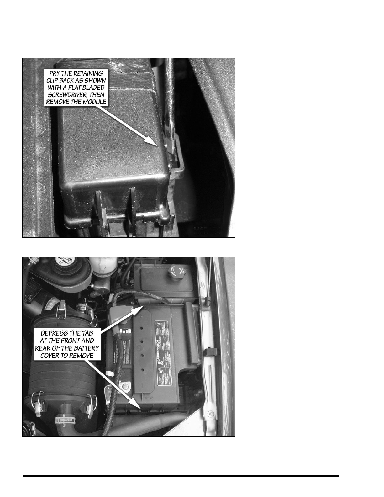
Figure 1. Electronic module near the driver side battery on 2005-06 4-wheel
drive equipped vehicles
Figure 2
emove Stock Components
R
1. Remove the (+) and (-) battery
cables from both the drivers and
assenger side batteries.
p
2. Undo the two toggle clamps at
the rear of the air box assembly.
3. Disengage the two tabs on the
lower backside of the air box
assembly from the slots on the rear
cover.
4. Remove the air box assembly and
air box front cover from the vehicle.
5. For 2005-06 4-wheel drive
equipped vehicles only:
electronics module near the driver
side battery shown in
retaining tab for the module can be
pried back with a flat blade
screwdriver as shown in the figure.
After the tab is depressed, the
module can easily be pulled away
from it's mounting bracket.
Remove the
Figure 1. The
6. Remove driver’s side plastic
battery cover. There are tabs at the
front and back of the cover that need
to be depressed to remove the cover,
as shown in
careful not to break the plastic box,
as it will be re-installed later.
Figure 2. Note: Be
7. Remove the driver’s side battery
hold down clamp (8mm socket).
8. Remove the driver’s side battery.
WARNING: When lifting a battery,
excessive pressure on the end
walls could cause acid to spew
through the vent caps, resulting in
personal injury. Lift with a battery
carrier or with hands on opposite
corners. Failure to follow these
instructions may result in
personal injury.
9. Remove the wire harness plastic
retaining clip on the back of the
plastic battery box.
10. Remove the plastic battery box
[(4x) 13mm socket].
4-wheel drive equipped vehicles only:
A small bracket used to mount an
electronic module will also be
removed with the plastic battery tr
For 2005-06
ay.
96782 v.2.0 3
Page 4
11. Locate the driver side boost
tube. Loosen the hose clamps and
remove the boost tube, hose clamps
and hose (if applicable) from engine
compartment and set aside. These
arts will not be reused.
p
12. Remove the four allen head
bolts that attach the stock intake
elbow. The intake elbow is the 90
degree transition from the driver
side boost tube to the intake
anifold.
m
13. Remove the stock intake elbow
and gasket.
14. Cover the inlet to the intake
manifold to prevent debris from
getting into this area.
Modifications to make room for
the Banks Techni-Cooler System
15. For 2005-06 4-wheel drive
equipped vehicles only:
two retaining clips that attach the
wire harness to the metal battery
tray.
Remove the
16. Remove the driver’s side metal
battery tray [(3x) 13mm socket].
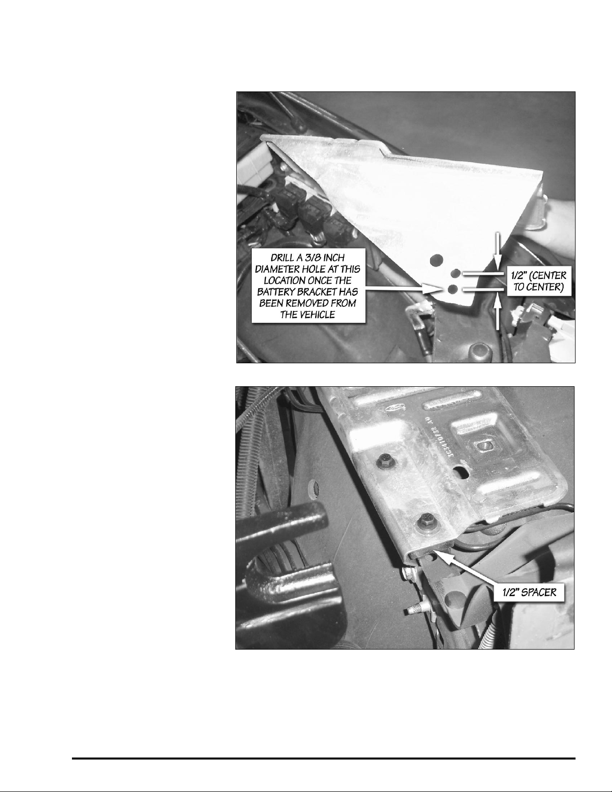
17. Drill a
Figure 3.
3
⁄8 inch hole as shown in
18. Reinstall the battery tray as
shown in
1
⁄2" spacer and longer supplied 8mm
bolts. Torque the bolts to 12 ft-lbs
Figure 4 with the supplied
Figure 3
Figure 4
4 96782 v.2.0
Page 5

igure 5
F
19. Trim the fan shroud as shown in
Figure 5 using Template 1 on page
9, to clear the Banks High Ram.
Note: 2005-06 vehicles require a
different trim to fan shroud, use
appropriate template. See
Template 1.
96782 v.2.0 5
Page 6

Figure 6 General Assembly Banks Techni-Cooler
9
9
8
10
1
5
6
7
12
13
3
2
4
15
14
11
Item Description P/N Qty
1 High-Ram Intake Manifold
2003-04 42745 1
2005-06 42746 1
2 Boost tube, left 41326 1
3 Hose, 3.5”x 3.25”, Black 94215 1
4 Hump Hose, 3” x 3”, Blue 94510 1
5 Gasket, High-Ram Intake 93038 1
6 Stud, High-Ram Air Intake M6-1.0 x 1⁄4-20 x 4.365 91534 3
7 Stud, High-Ram Air Intake M6-1.0 x 1⁄4-20 x 6.725 91535 1
Nut, Nylock
8
9 Washer, SAE Flat, Zinc 1⁄4” 91102 4
10 Washer, Thread Sealing 1⁄4”-20 91106 2
11 O-Ring. High-Ram 93606 2
12 Hose Clamp, 3.5” Spring Loaded 92897 2
13 Hose Clamp, 3.0” Spring Loaded 92860 2
14 Spacer, Battery Box 91890 1
15 Hex-Bolt, Washer Head, Black 8mm-1.25 x 30mm 91810 2
1
⁄4”
-20
1110 4
9
6 96782 v.2.0
Page 7

igure 7
NYLOCK NUT
STANDARD WASHER
THREAD SEALING
WASHER
BANKS HIGH RAM
O-RING
STUD
F
Figure 8
High-Ram Installation
pply the supplied thread locker
20. A
o the M6 threaded side of the High
t
Ram studs. The M6 thread length is
shorter than the
the opposite ends of the studs.
sing the two
21. U
provided, tighten the High Ram studs
into the intake manifold by threading
both nuts onto the stud. Tighten the
nuts against each other using two
open end wrenches, then tighten the
stud by turning the wrench on the top
nut. The stud should be torqued to 2-3
ft-lbs. Reverse the process to remove
the nut and repeat for each stud.
1
⁄4"-20 threads on
1
-20 nuts
⁄4"
22. 2003 to 2004 vehicles only.
Remove 0.75" of the split loom near the
connector shown in
provide additional clearance for the
High-Ram.
Figure 7 to
23. Install the supplied o-rings on
the two driver side studs as shown in
the exploded view in
Figure 8. Slide
96782 v.2.0 7
Page 8

he o-rings down to the base of the
t
ntake manifold.
i
24. For 2003 to 2004 vehicles,
install the factory replacement intake
manifold gasket in the groove on the
intake manifold.
ehicles,
v
eplacement intake manifold gasket
r
on the High Ram.
For 2005-06
nstall the factory
i
25. Slide the High-Ram over the
nstalled studs.
i
26. Place the thread sealing washers
on the two driver side studs. Use a
twisting motion to thread the sealing
washers over the threaded portion of
the studs to avoid tearing the seals.
Install standard flat washers on the
passenger side studs and on top of
the thread sealing washers, as shown
Figure 8.
in
27. Secure the High Ram with (4x)
1
⁄4"-20 Nylon locking nuts. Torque to
9 ft-lbs.
NOTE: Before slipping the boost tube
and the corresponding hose, into
position, ensure that all connection
ends are clean and free of any oil
residue and contaminates. Clean all
connection points with a
based solvent
Mineral Spirits, Denatured Alcohol or
Lacquer Thinner. Read and follow the
manufactures operation instruction
for non-oil based solvent cleaner.
such as Acetone,
non-oil
28. Locate the Banks boost tube,
connection hose, hump hose and
supplied hose clamps. Install hoses,
hose clamps and Banks boost tube
as shown in
Note: the connection hose should be
slid firmly against the hose stops
provided on the High Ram. Allow a
minimum
High Ram and boost tubes.
Figure 6.
1
⁄8” air gap between CAC,
igure 9
F
On 2003 to 2004 vehicles: The brake
line on the driver side may need to
be slightly bent to provide additional
clearance for the boost tube.
On 2005-06 vehicles: One of the
power steering fluid lines may need
to be bent to provide clearance for
the driver side boost tube.
29. The hose clamps on the High
Ram must be positioned as shown in
Figure 9 to avoid contact with the
hood.
30. Tighten the hose clamps to 75
inch-lbs (
not ft-lbs!).
31. Re-install the plastic driver side
battery box. Torque the attachment
bolts to 12 ft-lbs.
On 2005-06 4-wheel drive vehicles
only:
Reinstall the electronic module
mounting bracket that was removed
with the plastic battery tray.
32. Re-install the driver’s side
battery, battery hold down clamp,
and plastic battery cover. Torque the
hold down clamp retaining bolt to 89
WARNING: When lifting a
in-lbs.
battery, excessive pressure on the
end walls could cause acid to
spew through the vent caps,
resulting in personal injury. Lift
with a battery carrier or with
hands on opposite corners. Failure
to follow these instructions may
result in personal injury.
33. For 2005-06 4-wheel drive
equipped vehicles only:
electronic module near the driver
side battery
Figure 1.
The module is shown in
.
Re-install the
34. Re-install the air filter assembly
box and air box front cover.
35. Re-install the driver and
passenger (+) and (-) battery cables.
8 96782 v.2.0
Page 9

ALIGN WITH
SHROUD EDGE
03-04 SHROUD
SUPP
ORT PIN
2005-06 SHROUD
SUPP
ORT PIN
HIGH RAM
FAN
SHROUD TEMPLA
TE
SHROUD
SUPP
ORT PIN
2003-04
AREA TO T
RIM
2005-06
AREA TO T
RIM
Template 1
(fan shroud, step 19)
96782 v.2.0 9
Page 10

Notes
10 96782 v.2.0
Page 11

Notes
96782 v.2.0 11
Page 12

Gale Banks Engineering
546 Duggan Avenue • Azusa, CA 91702
(626) 969-9600 • Fax (626) 334 -1743
roduct Information & Sales: (800) 438-7693
P
Customer Support: (888) 839-5600
Installation Support: (888) 839-2700
bankspower.com
 Loading...