


with Installation Instructions
Owner’sManual
®
Banks PowerPack
System
Including:
®
Banks Stinger
Banks Git-Kit
Ford 6.8L V-10 Class-A Motorhome
System
™
THIS MANUAL IS FOR USE WITH SYSTEMS 49140, 49141, 49142, 49143,
49146, 49147, 49160 & 49161
Gale Banks Engineering
546 Duggan Avenue • Azusa, CA 91702
(626) 969-9600 • Fax (626) 334-1743
(800) 438-7693
roduct Information & Sales
P
Customer Support: (888) 839-5600
Installation Support: (888) 839-2700
bankspower
©2005 Gale Banks Engineering
.com
:
05/10/05 PN 96378 v.5.0

General Installation Practices
battery is disconnected. This is
Dear Customer,
If you have any questions
concerning the installation of
your Banks Stinger system,
please call our Technical Service
Hotline at (888) 839-2700
between 7:00 am and 5:00 pm
(PT). If you have any questions
relating to shipping or billing,
please contact our Customer
Service Department at
(888) 839-5600.
Thank you.
1. For ease of installation of you
Banks system, familiarize yourself with
the procedure by reading the entire
manual before starting work.
2. The exploded views provide only
general guidance. Refer to each step
and section diagram in this manual for
proper instruction.
3. Throughout this manual, the left
side of the vehicle refers to the
driver’s side, and the right side to the
passenger’s side.
4. Disconnect the ground cables from
the battery before beginning work. If
the vehicle has more than one battery,
be sure that the engine primary
necessary for safety and to ease the
installation of the passenger side
TorqueTube
®
exhaust manifold.
5. Route and tie wires and hoses a
minimum of 6 inches away from
exhaust heat, moving parts and sharp
edges. Clearance of 8 inches or more
is recommended where possible.
6. When raising the vehicle, support it
on properly weight-rated safety
stands, ramps or a commercial hoist.
Follow the manufacturer’s safety
precautions. Take care to balance the
vehicle to prevent it from slipping or
falling. When using ramps, be sure the
front wheels are centered squarely on
the topsides; put the transmission in
park; set the hand brake; and place
blocks behind the rear wheels. If the
vehicle is supported by a hoist, the
front wheels may be removed for
further accessibility.
use floor jacks to support the
vehicle while working under it. Do
not raise the vehicle onto concrete
blocks, masonry or any other item
not intended specifically for this
use.
7. During installation, keep the work
area clean. If foreign debris is
transferred to any Banks component.
Clean it thoroughly before installing.
CAUTION! Do not
2 96378 v.5.0

Tools Required
• 1 1⁄4” wrench
• 5mm 6 point socket
• Chisel or hacksaw
• Saw or torch
• Clean shop towels or rags
• Pry bar or channel lock pliers
1
⁄4” and 3⁄8” drive ratchets with
•
metric sockets and a
extension
• Metric combination or open-end
wrenches
• Standard and Phillips head
screwdrivers
• Penetrating oil or light lubricant
spray
• Standard and phillips head
screwdrivers
1
⁄4” drive
Table of Contents
General Assembly . . . . . . . . . . . . . . .4
Section 1 . . . . . . . . . . . . . . . . . . . . . . .6
Torquetube Manifolds
Section 2 . . . . . . . . . . . . . . . . . . . . . . .9
Monster Exhaust
Section 3 . . . . . . . . . . . . . . . . . . . . . .11
Ram Air Intake
Section 4 . . . . . . . . . . . . . . . . . . . . . .14
Ottomind Installation
Bill of Materials . . . . . . . . . . . . . . . .15
96378 v.5.0 3
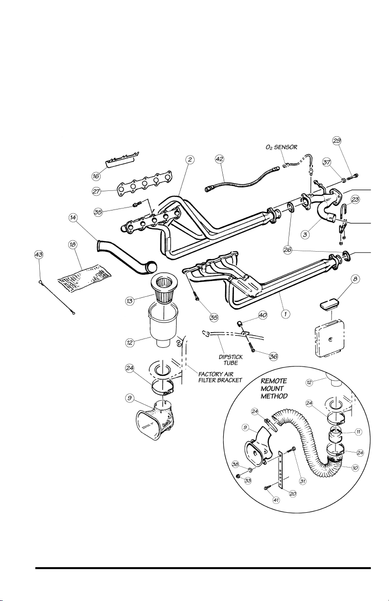
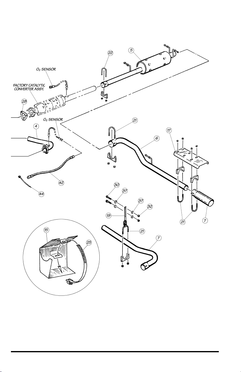
General Assembly
Figure 1 See Bill of Materials on page 15
4 96378 v.5.0
96378 v.5.0 5

Section 1
TORQUETUBE MANIFOLDS
For Git-Kit & Stinger installation,
proceed to
step 24.
1. The vehicle may have a bolted in
crossmember between the leveling
jacks at the front of the vehicle. This
will need to be removed prior to
removing the factory exhaust system
and reinstalled after the Banks
PowerPack system is place.
2. Locate the oxygen sensors in each
exhaust headpipe, downstream of the
factory exhaust manifolds. Unplug the
connectors and remove both the
oxygen sensors. Mark the sensors for
correct reinstallation.
3. Disconnect the three-bolt flange at
the front of the catalytic converter
from the factory Y-pipe assembly.
Disconnect the headpipes from the
exhaust manifolds and remove the Ypipe assembly from the vehicle.
4. On the driver’s side of the engine,
unscrew the EGR tube from the
exhaust manifold with a 1
and remove the EGR tube from the
manifold.
1
⁄4" wrench
5. Pull out the dipstick and remove
the small bolt that attaches the oil pan
dipstick tube to the cylinder head. At
the front of the vehicle, behind the
front engine cover, remove the 2
screws that retain the dipstick tube to
the radiator support. Near the exhaust
manifold, pull the dipstick tube up out
of the engine block. Check to see if
there is an O-ring on the tube. If not,
the O-ring may be stuck inside the
hole in the engine block. This O-ring
should be retrieved if necessary and
placed back onto the tube before
reinstalling it.
o remove the exhaust manifolds
6. T
use a wrench or socket to back the
nuts away from the manifolds at least
one turn,
socket to remove each stud from the
then use a 5mm 6 point
,
head. As an alternate method, take the
nuts off the studs, and then remove
the studs.
7. After the manifolds have been
removed from the vehicle, remove any
remaining studs from the heads. The
studs must be removed from the
heads in order to install the Banks
TorqueTubes.
8. On EGR models, remove the large
EGR adapter fitting from the left side
factory manifold and install it onto the
left Banks TorqueTube manifold. Reuse
the original copper washer between
the manifold and adapter. Use antiseize on the threads to prevent galling.
On non-EGR models, install the
pipe plug into the EGR fitting on the
manifold.
3
⁄4 npt
9. On the passenger side of the
engine, loosen the three rearmost
outside valve cover with bolts. Slide
the valve cover heat shield provided
under the heads of the bolts and
tighten. See
figure 2.
10. On some vehicles a wire loom
bundle runs along the top of the frame
rail adjacent to the driver’s side of the
engine. In these instances this loom
and any other wiring must be
relocated away from the exhaust
manifold heat area. Pry the wire loom
clips from the frame rail to provide
enough slack in the wire loom bundle
so it may be routed and tied up
against the underside of the floor of
the coach. The wire loom bundle may
be routed up braces adjacent to the
upper engine area and along
supporting members under the floor
with the cable ties provided.
11. Install the starter heat shield onto
the starter using the #52 hose clamp
provided.
heat shield does not come in
contact with the positive terminal
Caution: Make sure the
6 96378 v.5.0

Figure 2
of the starter once the heat shield
is tightened down. See figure 3
.
12. On some motorhomes there is a
vertical hose fitting on top of the air
conditioner compressor. (Skip this step
if your motorhome does not have the
vertical fitting.) Before installing the
right side TorqueTube, bend the hose
1
fitting
rail using a pry bar. Be careful not to
crease or puncture the fitting. This will
give clearance for the TorqueTube.
Wrap the hose with the supplied heat
shield blanket. Secure the blanket to
the hose with the supplied wire ties.
⁄4 - 1⁄2 inch towards the frame
13. Inspect the exhaust mounting
surfaces of the cylinder heads and
clean away any deposits to assure
proper sealing of the Banks
TorqueTubes. Be careful when doing
this as the cylinder heads are made
from aluminum, and can be easily
damaged. We recommend the use of a
Scotchbrite
®
pad.
14. Place a small amount of anti-seize
on the threads of each of the supplied
manifold bolts
provided when installing TorqueTubes.
Lift the Banks TorqueTube manifolds
into place and install one or two bolts
to hold them in position. Install the
remaining bolts into the heads and
Use the new gaskets
.
tighten. See
figure 1.
15. On EGR models, attach the EGR
tube to the adapter fitting in the Banks
Figure 3
96378 v.5.0 7

TorqueTube manifold. If necessary,
loosen the fitting at the top of the EGR
tube to allow the tube to be positioned
properly.
16. Make sure the O-ring is on the
dipstick tube, and reinstall it into the
hole in the engine block. Reattach the
dipstick tube bracket to the cylinder
head with the new, longer bolt and
spacer supplied. Reattach the bracket
at the radiator core support with the
original hardware and put the dipstick
back in.
17. If additional clearance at the front
of the right side TorqueTube manifold
for the air conditioning hose is needed,
very gently bend the line away from
the manifold until there is a minimum
3
of
⁄4" of clearance. Do not use a pry
bar or other tool to bend it as this may
damage the line. Wrap the air
conditioning line with the aluminum
heat shielding blanket provided, and
tie it with the supplied wire ties.
18. If it was removed, reinstall the
crossmember at the front of the
vehicle.
19. Place the new catalytic converter
flange gasket onto the studs on the
catalytic converter flange. Install the Ypipe onto the catalytic converter using
the original hardware, and the pin
hanger into the rubber hanger on the
frame of the vehicle. Place a conical
seal into the flare at the forward end
of the Y-pipe, and attach the Y-pipe to
the right side TorqueTube manifold
using the
washers provided. Do not tighten the
bolts yet.
20. Slip a 2
free end of the Y-pipe, and then slide
the Y-pipe extension into the slip joint.
With the slip joint fully seated, mark
the extension pipe with a pen so that
as the clamp is tightened, any slippage
of the joint can be observed. Place the
3
⁄8" x 13⁄4" bolts and
1
⁄2" muffler clamp over the
second conical seal onto the flare on
the extension, and attach the
extension pipe to the left side
TorqueTube with the
and washers provided. Tighten the
1
2
⁄2" clamp at the slip joint, observing
the mark to be sure the joint stays
fully seated as the clamp is tightened.
1
Up to
⁄4" slip is acceptable. Tighten
the bolts at the manifold collectors.
3
⁄8" x 13⁄4" bolts
21. Install and tighten the oxygen
sensors into the threaded bungs
provided on the Y-pipe and extension.
Use a small amount of anti seize on
the threads of the oxygen sensors. Be
careful to not get any anti-seize on the
sensor elements themselves.
22. On the connector on the oxygen
sensor and on the male connector on
the sensor extension lead, remove the
two index pins on the connector shell,
by cutting or filing. Be careful to not
damage the locking mechanism of the
connectors. See
figure 4.
23. Plug the oxygen sensor extension
leads included in the kit into the wiring
harness where each sensor was
previously connected, then plug the
sensor lead into the extension. Secure
the leads away from any pipes or
moving linkages with the cable ties
provided.
-END, SECTION 1-
Figure 4
8 96378 v.5.0

Section 2
MONSTER EXHAUST
24. Disconnect and remove the
factory tailpipe and muffler from the
rear of the factory intermediate pipe.
Start from the rear and work forward,
prying the pins from the rubber
hangers, removing the tailpipe, then
the muffler. If the slip joints will not
come apart, use a torch to heat the
connections until they separate, or cut
the pipes apart with a saw or torch,
being careful to not cut the outlet
portion of the intermediate pipe. Save
all hardware and hangers as some
items will be reused in the PowerPack
installation.
208” may need to use extension kit
P.N. 49097.
Figure 5
NOTE: Wheelbases over
25. Slide a 3" exhaust clamp over the
forward end of the Banks Dynaflow
muffler assembly and install the
assembly onto the end of the catalytic
converter outlet pipe. Position the pin
hangers on the muffler assembly into
the rubber hangers on the frame, and
adjust the rotation of the muffler as
necessary to position the hanger pins
level in the vehicle. Make sure that the
hangers are hanging forward. This will
allow the hangers to swing as the
exhaust system expands while the
engine is running. With the muffler
level and square to the frame of the
vehicle, tighten the clamp on the
muffler assembly inlet.
®
96378 v.5.0 9

26. Two tailpipe options are available
to provide either a right side or left
side tailpipe exit. Refer to the
installation steps that are appropriate
to your installation.
Left exit tailpipe: position a 31⁄2" clamp
over the muffler outlet, and place the
Banks Monster tailpipe up over the
driveshaft and slide it into the outlet of
the muffler. Place the pin hanger on
the pipe into the rubber hanger
attached to the left side of the frame.
Support the pipe level with the vehicle
and tighten the clamp.
Right exit tailpipe: place a 31⁄2" clamp
over the muffler outlet, and insert the
Banks Monster tailpipe into the end
of the muffler. Attach the universal
hanger to the tailpipe with a 3
clamp, then find a suitable hole in the
frame rail directly over the tailpipe.
With the tailpipe supported level with
the vehicle, bolt the hanger into the
1
⁄2"
5
hole with the
washers and nuts also provided.
⁄16" x 11⁄4" bolt,
27. Mount the floor heat shield and
polished tip onto the pipe using the
1
3
⁄2" clamps provided, as shown in
figure 5.
28. Lower the vehicle and reconnect
the battery cables. Start the engine
and listen for any exhaust leaks.
Tighten bolts or clamps to correct any
leaks or make adjustment as required.
It is recommended that tack welds be
placed on all slip connections to
prevent slippage.
Note: The vehicle exhaust may smoke
upon initial start-up. This is normal, as
grease used in the tube-bending
process burns out of the pipes.
For Git-Kit installation,
complete.
-END, SECTION 2-
procedure is
10 96378 v.5.0

Section 3
RAM AIR INTAKE
Figure 6
CUT OFF TOP
PORTION OF
SCOOP AT THIS
POINT
1
⁄2"
MAKE FOUR 1⁄2 -
INCH DEEP SAW
CUTS AROUND END
OF SUPERSCOOP
OUTLET
29. Inside the vehicle with the engine
cover removed, find the rubber
bellows at the inlet of the throttle
body. Loosen the clamp attaching the
plastic air inlet tube to the bellows,
loosen it and pull the plastic air inlet
tube out of the rubber bellows. At the
front of the vehicle, loosen the clamp
that holds the forward end of the air
inlet tube to the air filter housing
elbow. Remove the tube from the air
filter housing, elbow and pull the tube
forward, out of the vehicle.
30. To install the Banks Ram-Air air
inlet tube into the vehicle, place the
forward end into the air filter housing
elbow, and the rear end into the
rubber bellows on the throttle body.
Tighten both clamps.
1
⁄2"
AIR FILTER
HOUSING
MODIFIED
SUPERSCOOP
NO. 64
HOSE
CLAMP
96378 v.5.0 11

31. Unlatch the clamp that holds the
two halves of the air filter housing
together and remove the original filter.
Remove and discard the plastic cover
from around the air inlet of the lower
housing. Remove the lower housing
from the vehicle by unhooking the
rubber strap from the mounting
brackets and pulling the housing
forward so that the feet disengage
from the rubber mounting grommets.
32. Install the Banks Ram-Air filter
housing in place of the factory
housing. Make sure that the mounting
feet fully engage the rubber grommets,
and the strap is reattached. Install the
Banks Ram-Air filter into the filter
housing. Reattach the upper half,
making sure the two halves are
properly seated together and latch the
clamp.
Note: The Banks Ram-Air Super-Scoop
may be installed in one of two
configurations. One method mounts
the scoop directly to the air filter inlet
at the bottom of the filter housing. This
method is the preferred method but
can only be used if there is room
below the air filter housing to
accommodate the Super Scoop. The
other method mounts the scoop to the
grille, or directly behind it, and
connects the scoop to the air filter
housing via a flexible hose.
To mount the scoop directly to the air
filter housing, follow the directions in
step 33. To mount the scoop to the
filter via the hose, skip
follow the directions in
thru 38.
step 33 and
steps 34
33. Cut off the curved portion of the
Super Scoop outlet
edge of the inlet lip as shown in
6
. Next make four saw cuts 1⁄2 inch
equally spaced around the cut
,
deep
end of the Super Scoop outlet. Deburr
the cut edges to remove plastic chips.
1
⁄2 inch above the
figure
Slide the modified Super Scoop outlet
over the inlet of the air filter housing,
aim the scoop inlet toward the vehicle
grille, and secure with a No. 64 hose
clamp positioned over the four saw
cuts. Proceed to
step 39.
34. Install the Banks Ram-Air hose
connector onto the bottom of the air
filter housing with a #64 hose clamp.
This part adapts the 3
filter housing to the 4" Ram-Air duct.
35. Determine a location for the Ram-
Air Super-Scoop
as low as possible, directly behind the
grille, with the air inlet opening
pointing directly forward in the vehicle.
1
⁄2" outlet of the
®
. It should be placed
36. The height difference between the
Super-Scoop and the air filter inlet
should be as great as possible,to
prevent any rain water not eliminated
by the water drain hole from climbing
into the air box. The curved outlet
section of the Super-Scoop may be
trimmed back if less bend is required
to make a more streamlined hose
routing.
37. Once a location has been
determined for the Super-Scoop,
mount it using one of the methods
outlined below.
The Super-Scoop may be mounted by
several means. If the grille consists of
horizontal bars, or a perforated screen
heavy enough to support it, the SuperScoop may be secured using four 14"
nylon cable ties slipped through the
ears on the Super-Scoop and through
the grille. See
An alternate method is to mount the
Super-Scoop using the four perforated
metal straps provided. These can be
bent as required,
ears with the
nylock nuts, and
washers provided.
ackets may be attached to any
the br
figure 7.
and attached to the
1
⁄4"-20 x 1-1⁄4" bolts,
3
⁄4" OD x 5⁄16" ID flat
The other end of
12 96378 v.5.0
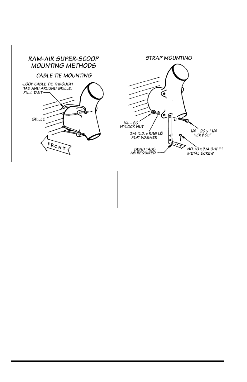
Figure 7
convenient mounting surface such as
the gravel pan, grille brackets, etc. as
required with #10 x
screws provided. A combination of
cable ties and straps may also be
used.
3
⁄4" sheet metal
38. Connect the Super-Scoop to the
hose connector using the 4" flexible
hose provided. The hose may be
shortened as needed. Secure the hose
with two #64 hose clamps.
-END, SECTION 3-
96378 v.5.0 13

Section 4
OTTOMIND INSTALLATION
39. Be certain battery ground cables
have been disconnected.
40. Locate the engine control unit
(ECU) under the dash mounted to the
left hand side of the steering column.
It will be housed in a black plastic case
bolted to the column. Loosen the bolt
attaching the electrical connector to
the ECU. This will be pointing toward
the floor of the coach.
41. Remove the bolts attaching the
1
ECU to the bracket using a
drive 5.5mm socket and ratchet. A
swivel and/or a
may be required to remove one or
more bolts. Pull off the electrical
connector and remove the plastic case
and ECU from the vehicle.
1
⁄4-inch universal joint
⁄4-inch
42. Note the code printed on the
plastic cap on the back of the ECU.
This code should compare to the code
printed on the Banks OttoMind label.
Pry the plastic cap from the rear of the
ECU using a small screwdriver,
exposing the printed circuit board
edge connector inside. Retain the
plastic cap. The connector will be
coated with grease and a clear silicone
type coating, which must be
completely removed before installing
the Banks OttoMind engine calibration
module.
43. Using a 5.5mm nut driver, loosen
and remove the six bolts that hold the
case of the ECU together. Open the
case of the ECU, being careful not to
lose the plastic spacer or damage any
circuitry inside the ECU.
44. Clean BOTH sides of the
connector. First, clean the white
grease off with a tissue. Next, scrape
the clear silicone type coating from
the connector fingers with the
THIS SCREW MAY
BE OMITTED UPON
REASSEMBL Y
LEAVE
TWO RIBS
INTACT
CUT OUT AND DIS-
CARD THIS POR
TO CLEAR OTTOMIND
14 96378 v.5.0
3/4
TION
"
LEAVE THIS
RIB INTACT

abrasive square provided. It is very
important to clean both sides of the
board in order to have a good
connection between the ECU and the
Banks OttoMind module. It is only
necessary to clean the connector
fingers. Be careful not to damage any
circuit traces on the board further
inside the ECU. Reassmeble the ECU
case and tighten the screw.
45. Orient the module so that its
edges line up with the edges of the
ECU case. If the edges do not line up,
the module is rotated 180 degrees off.
Place the OttoMind module over the
connector, and press firmly to set the
connection. DO NOT FORCE the
OttoMind onto the connector, as
damage may result to either the ECU
or the module. If the module does not
Bill of Materials
install with firm pressure, check the
orientation and try again.
46. A portion of the black plastic case
must be cut away to provide clearance
for the Ottomind module. Using
8
as a guide, cut away the portion of
the case between the first rib on the
right side and second rib on the left
3
⁄4-inch in from the corner as
side,
shown. A band saw or hack saw works
well for this job. Deburr the edges and
reinstall the ECU in the plastic case,
then reinstall ECU and case in the
vehicle. The one corner screw shown
may be omitted, as it is very difficult to
reinstall. Reattach the electrical
connector to the ECU and tighten the
retaining bolt.
-END, SECTION 4-
figure
FIG.#1 COMPONENT
1 TORQUETUBE, Left – – 3
2 TORQUETUBE, Right – – 3
3 Y-PIPE – – 3
4 Y-PIPE EXTENSION – – 3
5 DYNAFLOW MUFFLER 33 3
6 MONSTER TAILPIPE 3 3 3
7 TAIL PIPE TIP 33 3
8 OTTOMIND (Optional) – 33
9 SUPER-SCOOP – 3 3
10 HOSE, Air duct 4" x 5' – 3 3
11 CONNECTOR, Ram-Air Hose – 33
12 HOUSING, Air Filter – 33
13 AIR FILTER ELEMENT – 3 3
14 AIR INLET
15 HEAT SHIELD, Starter – – 3
16 HEAT SHIELD, Valve Cover – – 3
17 HEAT SHIELD, Tail Pipe Extension 33 3
18 HEAT SHIELD, Blanket – – 3
19 HANGER,
20 (4) MOUNTING STRAP
TUBE
Exhaust
(Right Exit Only) 3
GIT-KIT STINGER POWERPACK
–
–
3
33
3
96378 v.5.0 15
3
3

FIG.#1 COMPONENT
GIT-KIT STINGER POWERPACK
21 (3) CLAMP, Exhaust, 31⁄2” HD 33 3
22 CLAMP, Exhaust, 3” HD 33 3
23 CLAMP, Exhaust, 21⁄2” HD – – 3
24 (3) HOSE CLAMP, #64 – 33
25 HOSE CLAMP, #52 – – 3
26 (2) CONICAL SEAL, Exhaust Outlet – – 3
27 GASKET, TorqueTube – – 3
28 GASKET, Catalytic Converter – – 3
29 (4) BOLT,3⁄8” 16 x 13⁄4” Hex – – 3
30 (2) BOLT,5⁄16” 18 x 11⁄4” Hex (Right Exit Only) 33 3
31 (4) BOLT,1⁄4” 20 x 11⁄4” Hex – 33
32 (2) NUT,5⁄16” 18 Nylock (Right Exit Only) 33 3
33 (4) NUT,1⁄4” 20 Nylock – 33
34
35 (20) BOLT, 8mm x 1.25 x 30mm – – 3
36 BOLT, 6mm x 1.00 x 25mm – – 3
37 (4) WASHER,3⁄8” SAE (Right Exit Only, except PowerPack) 33 3
37 (8) WASHER,3⁄8” SAE (Right Exit Only) – – 3
38 (4) WASHER,1⁄4” USS – 33
39 WASHER, Metric 6mm – – 3
40 SPACER, Manifold Bolt – – 3
41 (4) SCREW, #10 x 3⁄4”–33
42 (2) WIRE EXTENSION, O2Sensor – – 3
43 (5) WIRE TIES – – 3
(4) CABLE TIES, 15” – 33
44 (10) CABLE TIES, 8” – 3 3
KIT, Service, Ram-Air – 33
ANTI-SEIZE, 1oz –– 3
POLISH, Metal, 3 Grams 33 3
OWNERS MANUAL 3 33
(3) UROCAL, “Banks Power” – – 3
(2) DECAL, “Banks Power”, Large 33 –
(2) DECAL, “Banks Power”, Small 33 –
WARRANTY STATEMENT 3 33
CARD, Product Registration 33 3
Gale Banks Engineering
546 Duggan Avenue • Azusa, CA 91702
(626) 969-9600 • Fax (626) 334-1743
Product Information & Sales: (800) 438-7693
Customer Support: (888) 839-5600
Installation Support: (888) 839-2700
bankspower.com
 Loading...