


________________________________________________
Preliminary
USER MANUAL FOR THE
CORNERSTONE TRANSMITTER
Model: CT-X
and the
CORNERSTONE 45 WATT AMPLIFIER
Model: CT-45
September 30, 2009
GALCOM INTERNATIONAL
115 Nebo Rd., Hamilton, Ontario, Canada, L8W 2E1
Phone: (905) 574-4626 - Fax: (905) 574-4633 - www.galcom.org
Providing durable technical equipment for communicating the Gospel worldwide
________________________________________________
1

TA B L E OFCONTENTS
TABLE OF CONTENTS .................................................................................................... 2
Section 1 – General Description ......................................................................................... 4
Section 2 – CT-X Transmitter Hardware ............................................................................ 5
2.1 Front Audio Inputs ............................................................................................... 5
2.2 Rear Audio Inputs ................................................................................................ 5
2.3 Contrast Adjustment ............................................................................................. 6
2.4 RF Output Connector ........................................................................................... 6
2.5 CT-X Digital IO Connector .................................................................................. 6
2.6 Power Socket and Switch ..................................................................................... 6
2.7 Ethernet Connection ............................................................................................. 7
2.8 Case Configuration ............................................................................................... 7
2.8.1 Rack Mount Configuration ........................................................................... 7
2.8.2 45 Degree Desktop Configuration ................................................................ 7
2.9 Cleaning the Transmitter ...................................................................................... 7
2.10 Touchscreen Display ........................................................................................ 8
Section 3 - CT-45 Hardware ............................................................................................... 8
3.1 RF Input Connector .............................................................................................. 8
3.2 RF Output Connector ........................................................................................... 8
3.3 Power Connector .................................................................................................. 8
3.4 CT-45 Digital IO Connector ................................................................................ 9
3.5 Main Power Toggle Switch .................................................................................. 9
3.6 Power Switch........................................................................................................ 9
3.7 Power LED ......................................................................................................... 10
3.8 Amplifier LED ................................................................................................... 10
Section 4 - Step by Step Installation and Setup ................................................................ 11
4.1 Installing the CT-X Transmitter ......................................................................... 11
4.1.1 Unpacking the CT-X ................................................................................... 11
4.1.2 Installing in a 19” Rack ............................................................................... 11
4.1.3 Installing the 45 Degree Wings ....................................................................... 11
4.1.4 Connecting the cables to the CT-X Transmitter ......................................... 12
4.1.5 Unpacking the CT-45 Amplifier ..................................................................... 12
4.1.6 Installing the CT-45 into a 19” Rack .......................................................... 12
4.1.7 Connecting the CT-X Transmitter to the CT-45 Amplifier ........................ 13
4.1.8 Verify the hardware installation .................................................................. 13
Section 5 – Software Operation (CT-X & CT-45) ........................................................... 14
5.1 Quick setup ......................................................................................................... 14
5.2 Views Menu ....................................................................................................... 15
5.2.1 Views / Frequency ...................................................................................... 15
5.2.2 Views / All ....................................................................................................... 15
5.2.3 Views / Temperature ....................................................................................... 16
5.2.4 Views / Levels.................................................................................................. 16
5.3 Settings Menu ..................................................................................................... 16
5.3.1 Settings / Frequency .................................................................................... 16
2

5.3.2 Settings/Input .............................................................................................. 17
5.3.3 Settings/Audio............................................................................................. 17
5.3.4 Settings/Mix ................................................................................................ 18
5.3.5 Settings/Password ....................................................................................... 18
5.3.6 Settings/Temperature .................................................................................. 18
5.3.7 Settings/Clock .................................................................................................. 19
5.3.8 Settings/Subcarrier ........................................................................................... 19
5.3.9 Settings/Files ............................................................................................... 19
5.4 Modules menu .................................................................................................... 19
5.4.1 Modules/CT-45 ........................................................................................... 20
5.5 Modes ................................................................................................................. 21
5.5.1 Modes/Advanced ........................................................................................ 21
5.5.2 Modes/Mixer ............................................................................................... 21
Section 6 – Mixer Mode ................................................................................................... 22
6.1 Operation of mixer mode ................................................................................... 22
Section 7 - Technical Specifications ................................................................................. 23
7.1 Cornerstone Transmitter CT-X ............................................................................... 23
7.2 Cornerstone Amplifier CT-45 ................................................................................. 25
3

Section 1 – General Description
Galcom’s Cornerstone Transmitter CT-X is a rugged, all digital transmitter designed for
use around the world. It is a compact unit approximately 9” x 6” x 4” (23cm. x 15cm. x
10cm.) with a small attached stand for desk operation, or attachable wings for 19” rack
mount. Inputs for microphones, CD player, MP3 player, internet connection, etc. are all
built into the unit. A touch screen display allows for immediate access and input of all
required settings as well as providing an on screen mixer.
As a stand alone unit the CT-X Transmitter can broadcast in FM 88 MHz - 108 MHz
generally to a large auditorium. This unit is ideal for use in countries where technology
and reliable electricity are limited. Its advanced digital design and user friendly touch
screen operation make it easy to install and operate. With its rugged construction, it is
designed for use in all climates and widely varying conditions.
The electrical power configuration for the CT-X operates on 100-230VAC while the CT45 operates on 110 or 220 VAC. Where reliable power is not available, with the addition
of a solar power supply, it can operate on 12-24 VDC and provide the power to the CTX.
As its name implies, the Cornerstone Transmitter is the foundational unit for several
additional amplifiers that will expand its reach to an entire city and beyond. The first
amplifier in this series is the CT-45 which only operates in conjunction with the
Cornerstone Transmitter CT-X. The expansion to a 450 Watt amplifier is planned in the
future.
Some of the features of this system include a stereo encoder, an audio processer, six
channel input, SCA, touch screen control, SWR monitoring, optional Ethernet card,
complete mixing of inputs, pre-emphasis and a “save and restore” option for all settings.
The following pages provide detailed instructions for installing and operating this system.
4
Section 2 – CT-X Transmitter Hardware
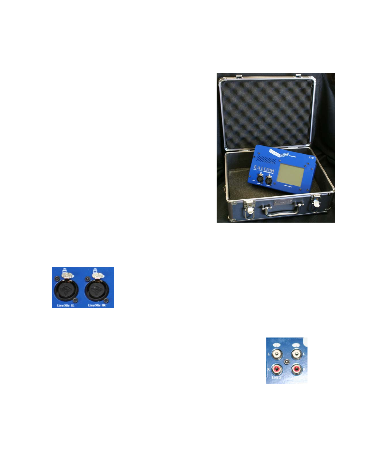
The CT-X Transmitter is a small, lightweight radio
transmitter that is ideal for transmitting a short
distance in auditoriums. With the addition of the CT45 Amplifier the signal can be boosted to 45 Watts of
power. The CT-X Transmitter is not designed for use
with amplifiers from other manufacturers.
2.1 Front Audio Inputs
There are two audio input plugs on the front of the transmitter
labeled Line/Mic 1L and Line/Mic 2L. These are balanced line
inputs. They will accept ¼” or XLR connectors, balanced or
unbalanced cables, and line level or microphone level inputs.
Ideally balanced XLR cables will be used for the input to the
transmitter.
2.2 Rear Audio Inputs
On the back of the transmitter there are an additional 4 audio
inputs labeled Line 2 L, Line 2 R, Line 3 L, and Line 3 R. These
accommodate RCA component level inputs.
5
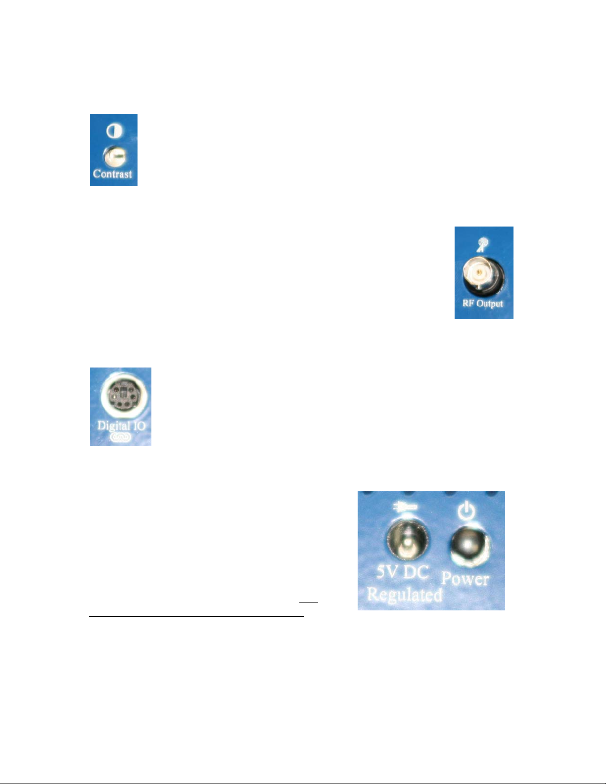
2.3 Contrast Adjustment
On the back of the transmitter there is a contrast dial that can be adjusted
with a small slot screwdriver. Turn the transmitter on and then adjust the
dial until the touchscreen display is easily visible.
2.4 RF Output Connector
On the back of the transmitter is a BNC connector labeled RF Output.
This is a 50 Ohm output port. This can be connected directly to an
antenna for broadcast to an auditorium or it can be connected to the CT-45
Amplifier.
2.5 CT-X Digital IO Connector
On the back of the transmitter there is a connector plug labeled Digital IO.
This is used when the transmitter will be controlling other devices such as
the CT-1 (this is a 1 Watt unit) or CT-45 Amplifier and also for future
options for the CT-X Transmitter.
2.6 Power Socket and Switch
On the back of the transmitter is a power socket
labeled 5VDC Regulated. The CT-X Transmitter
requires a regulated DC power supply. Use of
power adapters other than the one provided with the
Cornerstone Transmitter CT-X could cause damage
to the transmitter and to the power adapter. Use
only the power adapter supplied with the unit.
The toggle push button for turning the Cornerstone Transmitter on and off is labeled
Power and is located on the top of the unit.
6

2.7 Ethernet Connection
An Ethernet RJ-45 connector is located on the top of the transmitter. A separate network
card can be installed into the Cornerstone Transmitter which will allow for remote
monitoring and control of the Cornerstone Transmitter. Without the optional network
card installed into the CT-X, the Ethernet connection will not function.
2.8 Case Configuration
The CT-X case can be configured to sit flat on a table, to sit at a 45 degree angle or to be
installed in a standard 19” rack.
2.8.1 Rack Mount Configuration
The Cornerstone Transmitter case can be configured to be mounted on a standard 19 inch
rack. Included with the transmitter are two rack mount wings. These screw onto the
sides of the transmitter.
2.8.2 45 Degree Desktop Configuration
The Cornerstone Transmitter comes with two wings that allow it to easily be used on a
desktop. These wings screw onto either side of the Cornerstone Transmitter.
2.9 Cleaning the Transmitter
Do not use solvents, glass cleaner or abrasives on the touchscreen display. The display
screen can be damaged by harsh chemicals. To clean, gently wipe off the transmitter and
display with a damp cloth.
7
2.10 Touchscreen Display
On the front of the transmitter is a touch screen display. Included with the transmitter is a
stylus. A gentle touch with the soft plastic end of the stylus is all that is needed to control
all features of the Cornerstone Transmitter. Alternatively, the transmitter can be operated
with the touch of a finger. Avoid putting excessive pressure on the glass touch screen.
The touch screen display can be used in any lighting condition from direct sunlight to
total darkness.
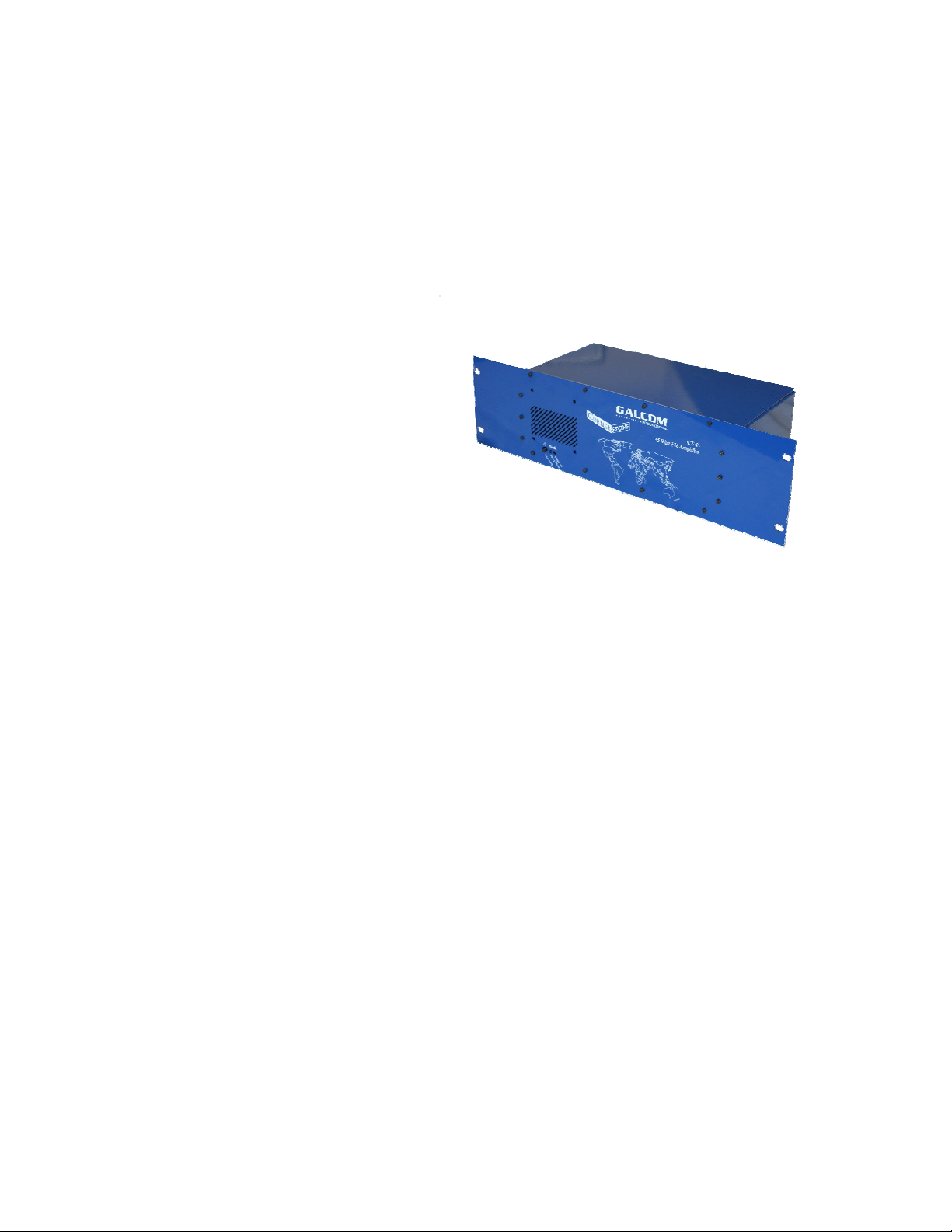
Section 3 - CT-45 Hardware
The CT-45 Amplifier is a 45 Watt RF
Amplifier. It is controlled by the CT-X
Transmitter. The touch screen on the CT-X
Amplifier must be used to control the CT-45
Amplifier.
The CT-45 Amplifier will only operate with the CT-X Transmitter. The CT-45 Amplifier
cannot be used with other manufacturers’ transmitters or exciters.
3.1 RF Input Connector
On the back of the CT-45 Amplifier is a BNC RF input connector. This is connected to
the CT-X Transmitter using 50 ohm BNC cable.
3.2 RF Output Connector
On the back of the CT-45 Amplifier there is an N-Type connector for connection to the
transmitting antenna. Using 50 ohm coax cable for the connection between the antenna
and the amplifier, it is important to ensure the cable between the antenna and the
amplifier is in good working condition. A short or open circuit can damage the CT-45
Amplifier.
3.3 Power Connector
8

The CT-45 Amplifier comes with a power cable that attaches to the power jack on the
back of the transmitter and to a North American 110 VAC power receptacle. If planning
to use the amplifier on 220 VAC toggle the switch on the back of the transmitter from the
110 position to the 220 position. Some countries may require different power cable or a
plug converter.
3.4 CT-45 Digital IO Connector
There is a round six pin connector on the back of the CT-45 Amplifier. This is used to
connect the control interface cable between the CT-45 Amplifier and the CT-X
Transmitter. This cable is a lower power data cable that enables the CT-X to monitor and
control the operation of the CT-45 Amplifier. To operate the amplifier this cable must be
connected to the transmitter. If it is unplugged while the amplifier is operating the CT-45
will turn the final output power off. In order to enable the amplifier the cable must be
reconnected and then either reboot the CT-X Transmitter or the menu option “Modules”:
click on “CT-45” and then click on “Pwr On”.
3.5 Main Power Toggle Switch
There are both a main power toggle switch and a power switch for the CT-45 Amplifier.
The main power toggle switch is located on the back of the amplifier. When this switch
is turned off all power is disconnected from the amplifier. When this switch is turned on
the amplifier will have power and if it is connected to the CT-X transmitter with the
Digital IO Cable it will be able to be monitored and controlled by the CT-X transmitter
however, to power up the amplifier both the main power toggle switch and the power
switch must be on.
3.6 Power Switch
The power switch is located on the front of
the CT-45 Amplifier and is labeled “Power
Switch”. It is a locking pushbutton switch.
It is in the “on” position if it is in and it is
“off” if it is out. Both the main power
toggle switch and the power switch must be
on for the amplifier to be able to be powered
up. Turning this switch off while the
amplifier is operating will result in the final
amp being turned off.
9

3.7 Power LED
There is a red power LED indicator on the front of the CT-45 Amplifier beside the Power
Switch. It is labeled “Power Indicator”. There are three states for this LED.
LED Off No Power - One or both of the power switches are off
LED Flashing Ready - The CT-45 has power and is ready for the
CT-X to power it up.
LED On Power On - The CT-45 is powered up
3.8 Amplifier LED
To indicate the state of the amplifier, there is a green LED located beside the power led
and labeled “Amplifier On”. This has two states.
LED off Amplifier is off
LED on Amplifier is on
The Cornerstone CT-X Software directly controls the operation of the amplifier. If the
switches are both on then the amplifier must be turned on by the CT-X Transmitter.
10

Section 4 - Step by Step Installation and Setup
4.1 Installing the CT-X Transmitter
4.1.1 Unpacking the CT-X
The CT-X comes in a metal carry case.
Please verify the following is included inside the case:
- CT-X Transmitter
- Power Supply
- BNC Telescoping Antenna
- Stylus
- Left and Right 19” Rack Mount Wings
- Left and Right 45 Degree Wings
- Instruction Manual
- Hex Key
- Keys for the Case
- Strap for the Case
4.1.2 Installing in a 19” Rack
If installing the CT-X into a 19” rack use the included hex key to remove the six screws
on either side of the transmitter. The Right 19” Rack Mount Wing is screwed onto the
right side of the CT-X with the screws that were previously removed. The Left 19” Rack
Mount wing screws onto the left side of the CT-X Transmitter using the screws that were
previously removed. Tighten the screws finger tight being careful not to over tighten and
strip the screws. It is best to leave an opening above the transmitter to make it easier to
connect cables and keep the transmitter cool. It is recommended to install the transmitter
into a 19” rack if the transmitter will be used with the CT-45 Amplifier.
4.1.3 Installing the 45 Degree Wings
Remove the six screws from both sides of the transmitter with the included hex key.
Attach the right 45 Degree Wing to the right side of the transmitter. The feet should
curve under the transmitter. Do the same for the left side of the transmitter. Tighten the
screws finger tight being careful not to over tighten and strip the screws.
11

4.1.4 Connecting the cables to the CT-X Transmitter
Plug the power adapter into a suitable power outlet. This can be 110VAC or 220VAC.
Connect the other end to the plug receptacle labeled “5V DC Regulated”.
For stereo operation connect the RIGHT balanced line output from the studio equipment
to the front of the CT-X Transmitter receptacle labeled “Line/Mic 1R”. Connect the
LEFT balanced line output from the studio equipment to the front of the CT-X
Transmitter receptacle labeled “Line/Mic 1L”.
Balanced line inputs are highly recommended however, if they are not available then
unbalanced ¼” cables can be used in the “Line/Mic 1R” and “Line/Mic1L” receptacles.
Component inputs can be used on the top of the CT-X transmitter. They are labeled
“Line 2 R”, “Line 2 L”, “Line 3 R”, and “Line 3 L”.
If the transmitter is being used as a stand alone device then connect the antenna to the
BNC jack on the top of the CT-X labeled “RF Output”.
4.1.5 Unpacking the CT-45 Amplifier
Please verify the following is included:
- CT-45 Amplifier
- Power cable for North America
- BNC Cable
- Digital IO Cable (6 pin cable)
- Instruction Manual
- Testing Results
4.1.6 Installing the CT-45 into a 19” Rack
If when the CT-45 is installed into the rack access to the back of the CT-45 will be
difficult or impossible proceed to 4.1.6 and connect the Amplifier before installing into
the rack.
We recommend leaving one rack unit open above and below the CT-45 for cooling.
Screw the CT-45 into the rack leaving one unit free above and below the CT-X
Transmitter.
12

4.1.7 Connecting the CT-X Transmitter to the CT-45 Amplifier
Connect the BNC cable supplied with the Amplifier from the “RF Output” plug on the
CT-X Transmitter to the “RF Input” plug on the CT-45 Amplifier.
Verify the position of the power supply voltage selection switch. It is either 115 Volts or
220 Volts. Connect the power cable between the amplifier and the wall receptacle.
Connect the 6 pin Digital IO Cable between the transmitter and the Amplifier.
Connect the Amplifier to the antenna cable. Make sure this is an N-Type fitting and that
the cable is properly inserted and tightened both to the Amplifier and the Antenna.
4.1.8 Verify the hardware installation
Turn on the CT-X Transmitter. It will immediately beep. The display shows the version
of the software on the top line and it will show the progress as the transmitter boots up.
Upon successful boot the transmitter will beep twice and go to the modulation display
screen.
If the CT-45 Amplifier is attached then turn the rear Main Power Toggle Switch to the
“on” position and make sure the Power Switch on the front of the CT-45 is pushed in.
Verify the red power light on the front of the CT-45 is flashing. On the CT-X
touchscreen display click on “Modules”. Verify that under the Modules menu there is an
option for “CT-45”.
13

Section 5 – Software Operation (CT-X & CT-45)
The CT-X is an entirely digital transmitter. It uses three digital signal processors to
digitally synthesize a radio wave. The main processor is responsible for the user
interface and communicating with the other two processors. The second processor of the
three is the Audio processor. This processor is responsible for the audio mixing, the
filtering, the pre-emphasis and the dynamic range control. The third processor is the RF
processor. Its entire job is to modulate the carrier wave.
5.1 Quick setup
After the CT-X is set up according to the instructions in section 4.1 it is time to configure
the transmitter using the touchscreen display. This section is intended to help get the
transmitter up and running without having to deal with all the extra options available.
For this quick setup we are assuming that the front two inputs (Line/Mic 1L and
Line/Mic 1R) are being used for the audio input from a line level balanced mixer.
Turn the Cornerstone Transmitter on and wait until it is finished booting. It will display
the menu at the top of the screen, the frequency in the middle and the modulation graph at
the bottom.
- Click on the Settings menu and then choose the option Frequency
There is a Frequency box, Stereo box and Bandwidth box
displayed
o Click on the Frequency box
There will be a number pad displayed similar to a calculator
o Enter the desired frequency and click on Enter
Note: The short left arrow is the backspace key and the large
one is the Enter key.
The backspace may need to be pressed to clear the previous
frequency
After pressing Enter you should see the new frequency in the
frequency box
o Verify the Stereo box is checked
o Verify the Bandwidth box is set to 100%
o Click OK
It will returned to the screen showing Frequency and
Modulation
- Click on the Settings menu and then choose the Input option
o Verify that the slider 1 Left and 1 Right are near the top
o Verify that both Mic level input boxes are not checked
o Click OK
14

- Click on the Settings menu and then choose the Audio option
o Verify that the FM 75 μS Pre-emphasis box is checked
o Click OK
- Click on the Settings menu and then choose the Mix option
This should show the mixing matrix
This is used to mix the various inputs to the desired outputs
o Verify that the only boxes that are checked are Input 1 Left to Output
Left and Input 1 Right to Output Right
This is the top right box and the second from the top, second
from the right
o Click OK
- Click on the Settings menu and the choose the Subcarrier option
o Verify that all of the bandwidth boxes (on the right) are set to 0
o Click OK
5.2 Views Menu
The views menu allows various screens to be selected that give information about the
transmitter.
5.2.1 Views / Frequency
This is the default display when the transmitter is turned on and when a setting is
changed.
This display shows the current frequency at the top of the screen. It shows the
modulation graph at the bottom of the screen. There is a slider on the left that controls
how quickly the modulation graph updates. The bar on the right shows the current
modulation.
5.2.2 Views / All
This view shows all the settings for the transmitter in text format.
15

5.2.3 Views / Temperature
This view shows two temperatures. The first temperature is the Direct Digital
Synthesizer temperature. This temperature should be <= 65.0 degrees Celsius.
The second temperature is the ambient temperature in the case. This temperature should
be <= 55.0 degrees Celsius.
5.2.4 Views / Levels
This view shows an overview of all of the audio input levels to quickly verify they are an
in acceptable range.
5.3 Settings Menu
The settings menu controls the operation of the Cornerstone Transmitter.
5.3.1 Settings / Frequency
This controls the carrier frequency for the transmitter. It also controls whether the
transmitter is in Stereo and whether the transmitter scales down its bandwidth.
The Frequency can be changed from 70 MHz to 108 MHz however, not all frequencies
are supported by all amplifiers. For example, the CT-45 Amplifier will only allow
frequencies in the range of 88 – 108 MHz. If you try to enable the amplifier with a
frequency outside of that range you will see an error message.
The Stereo check box is used to turn on the stereo carrier. It will inject a 19 kHz stereo
carrier at 9% total modulation. You will notice that if you turn the stereo carrier on and
then look at the Views / Frequency there will be modulation even if there is no audio
input.
The Bandwidth box is used to limit the total bandwidth. This is useful for narrow band
speech translation. Turn the stereo option off when you are using narrow band because
stereo is not support in narrow band transmission.
16

5.3.2 Settings/Input
You use the input sliders to control the input level of the audio. Sliding the slider to the
top increases the volume and sliding it to the bottom decreases the volume.
You will see the numbers 1, 2 and 3 across the top of the screen. These correspond to the
physical inputs on the Cornerstone Transmitter. Each input is broken into a Left and
Right channel. Channel 1 Left is the control for the input on the bottom right of the
Cornerstone Transmitter labeled “Line/Mic 1L”. Channel 1 Right is the control for
“Line/Mic 1R”. Channel 2 Left is the control for the white RCA input on the top of the
Cornerstone Transmitter labeled “Line 2 L”. Channel 2 Right is the red connector
labeled “Line 2 R”. Channel 3 Left controls the white RCA input labeled “Line 3 L” and
channel 3 Right controls the red RCA input labeled “Line 3 R”. Sliding the slider to the
top allows the audio into that input and sliding the slider all the way to the bottom will
mute that channel.
There are two check boxes labeled “Mic level input” under the sliders “1 Left” and “1
Right”. These are used to connect a microphone directly to the Cornerstone Transmitter.
This is useful when using the Cornerstone Transmitter for speech translation.
5.3.3 Settings/Audio
This screen allows you to control the pre-emphasis used with the transmitter. Clicking on
the 75 μS Pre-emphasis box will put a checkmark in the box and turn on the 75 μS preemphasis. Likewise, clicking on the 50 μS Pre-emphasis box will turn on the 50 μS preemphasis. To turn off the pre-emphasis click on the box that is checked to clear the
checkmark. Please note that you cannot turn on 75 μS pre-emphasis and 50 μS preemphasis at the same time.
Compression will control the audio level to maximize the volume without causing
distortion. The Compression targets 90% modulation. To enable compression click on
the compression check box as needed for FM, SCA 1 or SCA 2 and verify it has a check
mark.
DRC stands for Dynamic Range Compression. It is similar to compression but has a
quicker response time. To enable DRC click on the DRC check box for FM, SCA 1, or
SCA2 and verify there is a checkmark in that box.
We recommend having both Compression and DRC enabled.
17

5.3.4 Settings/Mix
This is likely the most difficult setting to configure however, the mixing matrix will give
you great flexibility configuring your transmitter. This is a mixing grid. It takes the
physical inputs and maps them to various possible transmitter outputs.
The inputs are listed at the top of the matrix. They are labeled 1 Left, 1 Right, 2 Left, 2
Right, 3 Left, 3 Right, and Ethernet.
The outputs are listed on the left side of the matrix. They are labeled Left, Right, SCA1,
SCA2, Ethernet.
Here is an example of how to mix input 2 Left to SCA1. Find the column under Input, 2,
Left and follow it down until you are at the row SCA2. Click on that square and verify it
now has a checkmark. Now all the audio coming into the Cornerstone transmitter
through the top connector labeled “Line 2 L” will be transmitted on the SCA2 channel.
Don’t forget to move “Input 2 Left” slider to the top under the Settings/Input menu and to
configure the SCA output under the Settings/SCA menu.
The most common configuration for this screen is to mix the input from the front two
audio inputs labeled “Line/Mic 1L” and “Line/Mic 1R” to the main radio left and right
channel.
5.3.5 Settings/Password
Use this screen to change the password for locking features on the transmitter.
5.3.6 Settings/Temperature
The transmitter will constantly monitor the DDS temperature, ambient temperature and
the temperatures for any modules attached such as the CT-45 Amplifier. You can
configure the levels here.
18

5.3.7 Settings/Clock
Set the time and date.
The time is in 24 hour format.
The date is set by day, month, year.
5.3.8 Settings/Subcarrier
The Cornerstone allows two audio subcarrier channels and an RBDS subcarrier channel.
Please note that there are limits on the subcarrier bandwidth. If you enter a combination
of bandwidths or frequencies that are above the maximum allowable bandwidth the
Cornerstone Transmitter will decrease the bandwidth to the allowable level.
For example, when in stereo mode, if you choose to have SCA1 at 67 kHz with a
bandwidth of 10% and SCA2 with a bandwidth of 30% the value for the SCA2
bandwidth will be changed to the highest allowable level and now show as 10%.
5.3.9 Settings/Files
You can save all of the changes that have been made to the transmitter in one of ten files.
To save the settings click on the slot number (0 – 9) that you want to save them in and
then click on “SAVE”.
To load a saved setting click on the slot number (0 – 9) that you want to recall and then
click “LOAD”.
Each time the transmitter is turned on it will have the same settings as when it was last
turned off.
5.4 Modules menu
The modules menu allows you to view and control other devices connected to the
Cornerstone Transmitter CT-X. This menu will be empty unless the CT-X is connected
to a module such as the CT-45 Amplifier by means of a Digital IO cable.
19

5.4.1 Modules/CT-45
The CT-45 option appears under the Modules menu only when the Cornerstone
Transmitter CT-X is turned on, the CT-45 Amplifier is turned on and the Digital IO cable
is connecting the two units.
The top of the screen shows the software version number for the CT-45
The “Target Pwr” box is used to control what wattage the amplifier will transmit. It has a
range of 0 to 50.
Under the target power box are status lines that tell what state the amplifier is in:
- “Power Ok:” this indicates the condition of the power supply. When the
power supply is off it will show the value “Low”. If the CT-45 Amplifier
detects a problem with the power it will switch to the “Low” state.
- “Enable Switch:” this indicates the position of the push button switch on the
front of the CT-45. When the switch is in it will display “Enabled” and when
the switch is out it will display “Disabled”.
- “Temperature:” this will show if a temperature error or warning has occurred.
Normally it will display “OK”.
- “PLL Lock:” this shows that the CT-45 Amplifier is locked onto the RF
signal from the CT-45 Transmitter. If the signal is ever lost and the CT-45
loses lock then the CT-45 will disable the amplifier. This displays “Locked”
or “Unlocked”.
- “Amplifier on:” this shows the state of the amplifier. When the amplifier is
on this will displayed “ON” and the green light on the front of the Amplifier
will be illuminated.
There are readings on the right of the screen:
- “SWR” this indicates the standing wave ratio at the output of the transmitter.
It is important to check the SWR at the antenna because it can be different
than the SWR reading at the transmitter due to losses in the antenna cable.
This will only display a value when the amplifier is on and the green
“Amplifer On” light on the front of the CT-45 is illuminated.
- “Fwd Pwr” this shows the output power of the CT-45 in watts.
- “Rfl Pwr” this shows the reflected power returning back to the CT-45 in watts.
- “Amb Temp” this shows the ambient temperature of the CT-45 in Celsius. It
will only display a temperature when the power is enabled.
- “Amp1 Temp” this will show the temperature of the first amplifier in the CT-
45 in Celsius.
- “Amp2 Temp” this will show the temperature of the second amplifer in the
CT-45 in Celsius.
There is a button at the bottom of the screen labeled “AMP Power”. When the amplifier
is turned off it will show “Pwr On” inside the button. Clicking the “Pwr On” button will
20

cause the CT-45 Amplifier to turn on the power supply, make sure the PLL is locked and
then turn on the amplifier.
When the amplifier is turned on the “Amp Power” button will display “Pwr Off”.
Clicking the “Pwr Off” button will turn the amplifier off and then turn the power supply
for the CT-45 off.
Please check the following before powering up the amplifier:
1) The Cornerstone Transmitter CT-X is installed correctly
2) The Cornerstone Amplifier CT-45 is installed correctly
3) The frequency and audio settings have been entered into the CT-X
4) Verify the connection from the CT-45 to the antenna.
5.5 Modes
There are two modes for the CT-X Transmitter. The advanced mode gives you the most
options.
5.5.1 Modes/Advanced
The Advanced mode allows for complete control for the transmitter. It allows for
configuration of external modules such as the CT-45 Amplifier.
5.5.2 Modes/Mixer
This mode will switch to a mixer mode. You will get a warning message that settings
will be changed. The mixer mode disables many features such as subcarrier and it will
also change most of the settings. See Section 6 for more information.
21

Section 6 – Mixer Mode
The mixer mode will allow for the mixing of two microphones and two auxiliary devices
to the main output of the transmitter.
6.1 Operation of mixer mode
Clicking the button “Change Mode” will change back to advanced mode.
The Mic1 slider controls the volume of the microphone plugged into the “Line/Mic 1L”
jack on the front of the CT-X Transmitter.
The Mic2 slider is for the “Line/Mic 1R” jack on the front of the transmitter.
The Aux1 slider controls the volume of the “Line 2 R” and “Line 2 L” port on the top of
the Cornerstone Transmitter.
The Aux2 slider controls the volume of the “Line 3 R” and “Line 3 L” port on the top of
the Cornerstone Transmitter.
The current frequency is displayed in the frequency box.
If the transmitter is in Stereo mode the Stereo box will be shown.
22

Section 7 - Technical Specifications
7.1 Cornerstone Transmitter CT-X
Model: CT-X
Power:
- 5.0 VDC (Includes 110VAC / 220VAC adapter)
- Regulated Voltage
- 2.5mm Cannon plug
- Internal self-resetting 1.2 Amp fuse
- Power switch
- 2.5 Watt power supply
- Power light on front of case
- Current Draw: 70 mA @ 110 Volts
Chassis:
- Rugged design
- Powder coated steel
- Wing attachments to fit in a 19” rack (3 Units)
- 45 degree leg attachments for desk use
Display:
- 320 x 240 Resolution
- Black and White
- Backlight
- Transflective (Can be used in sunlight or total darkness)
- Contrast adjustment
Touchscreen
- High resolution touchscreen panel
- Single point, pressure sensitive touch
- Can use stylus or finger
Digital IO Port
- Provides communication to other components such as the CT-45 Watt amplifier
- Future expansion (Such as radio programmer)
RF Output:
- Output Power: -8 dBm, .09 V RMS, 160
- Over voltage protection
- High pass filter
- FM Stereo
- FM Mono
- FM Subcarrier
- BNC jack
- Digitally synthesized output
- Frequency Stability: +/- 0.3 kHz over temperature range
- Subcarrier Frequency Stability: +/- 0.3 kHz
μW (into 50 Ohm Load)
23

Optional Ethernet Card:
- Stream audio to the internet
- Stream audio from the internet
- Built in web page
- Remote control of transmitter from any web browser
- Remote software upgradeable
Audio Inputs
- Audio Input 1 Left and 1 Right
o 2 x Dual XLR / ¼” jack
o Balanced or unbalanced input
o Mono or stereo ¼” plug
o Line level or Microphone level input
o 600 Ohm
- Audio Input 2 Left and 2 Right
o 2 x RCA jack (L & R)
o Unbalanced component input
o 10K Ohm
- Audio Input 3 Left and 3 Right
o 2 x RCA jack (L & R)
o Unbalanced component input
o 10K Ohm
Audio Processing:
- Pre-emphasis
o Off, 50 μS, or 75 μS
- Compression
- Dynamic Range Compression
Audio Mixing:
- 8 Input channels (1L, 1R, 2L, 2R, 3L, 3R, Internet L, Internet R)
- 6 Output channels (FM L, FM R, SCA1, SCA2, Internet L, Internet R)
- Mix any input or combination of input channels to any output channel
Software includes a ‘Mixing Mode’ program:
- One screen mixes two microphones and two auxiliary audio inputs to the FM output
- Adjustable on-screen sliders
- Entire radio show can be mixed from the touch screen of the transmitter
Temperature
- Monitor the ambient temperature
- Monitor the DDS temperature
- Warn when high temperature (Audio and visual warning)
- Shut down the transmitter if temperature reaches an unacceptable level
- Operational between 0 Celsius to 50 Celsius (Recommended below 25 Celsius)
Time and Date clock
- Record the time and date of errors (such as unacceptable temperature)
Includes:
- Durable padded carrying case
- Telescoping antenna
- Stylus
- AC Adapter (110V/220V with many common worldwide plugs)
- Instruction Book
- Rackmount wings
24

- 45 degree legs
7.2 Cornerstone Amplifier CT-45
Model: CT-45
The Cornerstone Amplifier CT-45 will only operate with the Cornerstone Transmitter CT-X.
Power:
- 120 Volt or 220 Volt AC
- Voltage selector on back
- Power switch on front
- Power light on front
- Current Draw: 930 mA @ 110 Volts (Includes the Cornerstone Transmitter CT-X)
Chassis:
- Powder coated steel
- Rugged design
- 19” Rack mount (3 Units)
- Quiet fan design
Digital IO
- Connection to control amplifier via the Cornerstone CT-X
- Must be connected in order to power up the amplifier
RF Input
- BNC input
RF Output
- Type N output
- FM Signal to Noise: -75dB
- AM Signal to Noise: -69dB
- FM Signal to Noise below 50Hz: -75dB
- Frequency Stability: +/- 0.3 kHz over temperature range
Temperature
- Temperatures monitored via cornerstone CT-X
- Monitor the ambient temperature
- Monitor power supply temperature
- Monitor final amplifier temperature
- Warn when high temperature (Audio and visual warning)
- Shut down the amplifier in case of over temperature
- Operational between 0 Celsius to 50 Celsius (Recommended below 25 Celsius)
Output Power
- >=45 Watts Output (88 – 108 MHz)
- SWR monitored via the cornerstone CT-X
- Monitor forward power at the amplifier
- Monitor reflected power at the amplifier
- Monitor the SWR at the amplifier
- Amplifier On output power light on front
- Warn when high SWR
- Shut down the amplifier in case of SWR >2.5:1
25

26
 Loading...