

Galaxy Control Systems 635 Series, 600 Series, 635 CPU, 600 DPI, 635 DPI/DRM Installation/configuration Manual
...
SYSTEM GALAXY
635 & 600 HARDWARE
INSTALLATION & CONFIGURATION
SG v11.2.0
S28 11.0.3
Oct 2019

System Galaxy
635-600 Series Hardware Manual
Revised
January 2019
635-600 Series Hardware Manual
Rev. 11.1.0.2
~ 2 ~

website for the latest updates and flash compatibility information. Visit us at
Galaxy Control Systems makes every effort to provide disclosures when referencing
products that are trademarked by other companies. The publisher states that it is
System Galaxy
635-600 Series
Hardware Manual
COVERING:
600 & 635
600 & 635 DPI/DRM Rev. E/F
DIO - Rev. C / D
DSI - Rev. B/C
Relay Board – all revisions
CPU
11th Edition, Jan 2019
Revision 11.1.0.2
Information in this document is subject to change without notice.
Therefore, no claims are made as to the accuracy or completeness of this document.
Integrated applications and 3
At the time this manual is published, all 600-series Hardware is compatible with System
Galaxy 11 software. See the board compatibility section in this guide to determine oldermodel board pairing requirements and upgrade path. Check the Galaxy Tech support
www.galaxysys.com
rd
Party Technologies my have additional requirements.
Copyright © 2019 Galaxy Control Systems All rights reserved
No part of this document may be reproduced, copied, adapted, or transmitted, in any form
or by any means, electronic or mechanical, for any purpose, without the express written
consent of Galaxy Control Systems. Copyright protection claims include all forms and
matters of copyrighted material and information, including but not limited to, material
generated from the software programs, which are displayed on the screen such as icons,
look and feel, etc.
Trademarks
referencing product names solely for editorial purposes, and to the benefit of the trademark
owners with no intent to infringe upon said trademarks.
The following trademarks are referenced in this manual:
®
Microsoft
Corporation in the U.S. and other countries.
HID
Corporation.
Farpointe logo and Farpointe Data are registered trademarks of Farpointe Data, Inc.
Galaxy Control Systems
SAGEM and MORPHO logos and MORPHO
Bioscrypt
Adobe
, Windows®, MSDE® and SQL Server
®
, HID iCLASS®, and HID Corporate 1000® are registered trademarks or logos of HID Global
®
®
are trademarks of their respective owners in the U.S. and abroad.
®
and Acrobat® are registered trademarks of Adobe Systems Inc.
, MorphoAccess®, SIGMA, Sagem, Invixium,
3 North Main Street
Walkersville MD 21793
www.galaxysys.com
TM
are registered trademarks of Microsoft
~ 3 ~

Table of Contents chapter-page
1 Overview, Safeguards, Specifications, and Requirements 1-1
1.1 What’s in this Manual (you are here) 1-1
1.2 IMPORTANT: Product Safety and Precautions 1-3
1.3 Hardware Certifications & Compliances 1-4
1.4 Hardware Replacement Parts 1-6
1.4.1 ORDERING POWER TRANSFORMER & BATTERIES.......................................................................................... 1-6
1.4.2 ORDERING REPLACEMENT BOARDS .............................................................................................................. 1-6
1.5 Hardware Capability: Panel-Level (CPU) 1-7
1.5.1 Controller Capability of the 600/635 Model Access Control Panel: ................................................................ 1-7
1.6 Hardware Capability: Board-Level 1-8
1.6.1 List of Boards and Component Descriptions: ................................................................................................. 1-8
1.7 Hardware & System Descriptions 1-10
1.7.1 Description of Galaxy Access Control Panel: ................................................................................................. 1-10
ENCLOSURE DIMENSIONS: 1-10
COMPONENTS IN THE DOMESTIC 8-DOOR CONTROLLER : 1-10
1.7.2 635/600-series CPU Description: .................................................................................................................. 1-12
1.7.3 635/600 DRM (DPI) Description: .................................................................................................................. 1-13
1.7.4 600 DIO Detailed Description: ...................................................................................................................... 1-13
1.7.5 600 DSI Description: ..................................................................................................................................... 1-14
1.7.6 600 RELAY BOARD Description: .................................................................................................................... 1-14
1.7.7 The System Described: ................................................................................................................................. 1-15
1.7.8 SG System Diagram – Communication/Event Server: ................................................................................... 1-16
1.7.9 SG System Planning Notes: ........................................................................................................................... 1-17
1.8 CPU & Board Flash Requirements for 600/635-Series Hardware 1-18
1.8.1 About Factory Flash and Field-Flashing the CPU: .......................................................................................... 1-18
1.8.2 About Auto-Updating the Daughter Boards: ................................................................................................ 1-19
1.8.1 Flash Version Compatibility Chart for SG-10: ................................................................................................ 1-19
1.8.2 Version Compatibility Charts for SG-9 and SG-8: .......................................................................................... 1-21
1.9 Controller Mounting Requirements 1-22
1.10 Power Requirements 1-24
1.11 Relay Ratings and Current Draw 1-25
1.12 Hardware Wiring Specifications 1-26
1.12.1 Controller Ethernet Communications: .......................................................................................................... 1-26
1.12.2 Hardware Wiring Specifications (Type, Gauge, Distance): ............................................................................ 1-26
1.13 Board Programming Requirements 1-27
page ~ i

1.14 Network & IT Requirements for Galaxy Hardware 1-29
1.15 Communication Requirements for System Galaxy Servers 1-30
1.16 Requirements for Logins and User Privileges (SG Software) 1-31
1.17 Pinout for Ethernet Cable (Cat-5e) 1-31
1.18 General FAQs about Features of Galaxy Hardware 1-32
2. Hardware Installation Instructions 2-1
LIST OF TABLES IN THIS CHAPTER 2-2
LIST OF FIGURES FOUND IN THIS CHAPTER 2-3
STEP 1. Hardware Install ~ Site Preparation 2-5
1.1 Conducting a Site Survey................................................................................................................................... 2-5
Overall System Architecture: 2-5
Technical Certification: 2-5
Controller Power Supply and Power Sources: 2-5
1.2 Requirements and Safeguards .......................................................................................................................... 2-7
SAFEGUARDS: 2-7
REQUIREMENTS: 2-8
1.3 About Upgrading Hardware / Expanding Systems ............................................................................................. 2-9
WHEN IS UPGRADING THE HARDWARE REQUIRED? 2-9
WHEN IS UPGRADING THE SG SOFTWARE REQUIRED? 2-9
1.4 Board Compatibility and Capability (635 vs. 600 models) ................................................................................ 2-10
NOTES ABOUT REPAIR / MAINTENANCE / UPGRADE OF 600-MODEL CONTROLLERS 2-10
STEP 2. Mount the Controller Enclosure/Cabinet 2-11
2.1 Choose a good location for the Controller ....................................................................................................... 2-11
EXPOSURE 2-11
2.1.2 MOUNTING REQUIREMENTS 2-11
2.2 Running Field Wiring ........................................................................................................................................ 2-12
2.3 Mount the Controller Cabinet .......................................................................................................................... 2-13
STEP 3. Install Power Connectors inside Controller 2-14
3.1 Remove Heat Shrink (only from wires to be used) ........................................................................................... 2-14
3.2 Wire the CPU Power Connector and Tamper Switch ........................................................................................ 2-15
3.3 Wire the “A/C Fail” and “Low Battery” to Sense Connector ............................................................................. 2-16
3.4 Wire the Power Connectors for the Boards (DRM, DIO, or DSI) ........................................................................ 2-17
STEP 4. Install the CPU and Interface Boards (daughter boards) 2-18
4.1 Install the 635-CPU Board inside Controller ..................................................................................................... 2-18
4.2 Installing a 635-DRM Board (Dual Reader Module) .......................................................................................... 2-19
635-DRM - BOARD FEATURES 2-19
635-DRM - INSTALL REQUIREMENTS 2-20
635-DRM – BOARD INSTALLATION (STANDARD OPERATION) 2-21
PART 4.2.1 PRE-CONFIGURING THE SUPERVISION RESISTORS 2-21
PART 4.2.2 SETTING THE LOCK RELAY JUMPERS 2-22
PART 4.2.3 (REQUIRED) PRE-CONFIGURING THE BOARD ID 2-23
PART 4.2.4 (REQUIRED) INSTALLING THE 635 DRM BOARD IN THE CONTROLLER 2-24
4.3 Install the DIO Board in the Controller ............................................................................................................. 2-25
page ~ ii

600-DIO - BOARD FEATURES 2-25
600-DIO – BOARD INSTALLATION 2-26
4.4 Installing a 635 DSI Board (Dual Serial Interface) ............................................................................................. 2-27
635-DSI - BOARD FEATURES 2-27
635-DSI - BOARD SPECIFICATIONS 2-28
THE 635-DSI SUPPORTED TECHNOLOGIES 2-28
635-DSI MAX NO. OF DEVICES & DEVICE COUNT (per Section) 2-29
635-DSI Examples of How DSI Sections Function Independently 2-30
635-DSI – BOARD INSTALLATION 2-31
PART 4.4.1 (OPTIONAL) PRECONFIGURING THE EOL TERMINATION JUMPERS (635-DSI) 2-31
PART 4.4.2 SETTING THE PASS-THRU VOLTAGE JUMPERS 2-32
PART 4.4.3 (REQUIRED) PRE-CONFIGURING THE BOARD ID 2-33
PART 4.2 4 (REQUIRED) INSTALLING THE 635 DSI BOARD IN THE CONTROLLER 2-34
4.5 Installing a 635-Model Output Relay Board ..................................................................................................... 2-35
635-OUTPUT RELAY BOARD - FEATURES 2-35
635-RELAY BOARD – INSTALLATION OF BOARD IN CONTROLLER 2-36
PART 4.5.1 PREP STEPS - BEFORE INSTALLING THE RELAY BOARDS 2-36
PART 4.5.2 CONFIGURE THE RELAY BOARD IDs (REQUIRED) 2-38
PART 4.5.3 INSTALLING THE BOARDS IN THE PANELS (REQUIRED) 2-39
4.6 Installing 635-Model Input Module .................................................................................................................. 2-43
635-INPUT MODULE - FEATURES 2-43
635-INPUT MODULE – INSTALLATION OF BOARDS IN CONTROLLER PANELS 2-44
PART 4.6.1 PREP STEPS - BEFORE INSTALLING THE INPUT BOARDS 2-44
PART 4.6.2 CONFIGURE THE BOARD IDs (REQUIRED) 2-46
PART 4.6.3 INSTALLING THE BOARDS IN THE PANELS (REQUIRED) 2-47
STEP 5. Applying Power to the Controller 2-52
5.1 Pull all field wiring into the controller .............................................................................................................. 2-52
5.2 Connecting Back-up Battery and Power Transformer to the Power Supply ...................................................... 2-52
5.3 About adding an Auxiliary Power Supply inside the Controller ....................................................................... 2-53
5.4 About External Power Supplies outside the Controller .................................................................................... 2-53
5.5 Installing Suppression Diodes at the Door Locks .............................................................................................. 2-53
STEP 6. Program the 635 CPU Board 2-54
6.1 Connecting to the CPU Board via Putty® or HyperTerminal® ............................................................................ 2-54
6.1 Programming the 635-Model CPU Board via Web Page ................................................................................... 2-55
STEP 7. Set the Interface Board ID’s (DPI/DIO/DSI) 2-60
7.1 Apply power to the “Daughter” Boards (DPI/DIO/DSI) .................................................................................... 2-60
7.2 Verify Board ID is Correct for Daughter Board(s) (DRM/DIO/DSI) .................................................................... 2-61
7.3 Verify Flash Version is Correct for Daughter Board(s) (DRM/DIO/DSI) ............................................................. 2-61
7.4 Flash Version Chart .......................................................................................................................................... 2-62
STEP 8. Connect the Controller CPU to the Network 2-63
8.1 Connect the CPU to the Ethernet LAN .............................................................................................................. 2-63
8.2 Verify Connection to the Event Server ............................................................................................................. 2-64
STEP 9. Test the Controller (recommended) 2-66
9.1 SOFTWARE PROGRAMMING QUICK NOTES: .................................................................................................... 2-66
9.2 TESTING PANELS with WEB PAGE OR SOFTWARE COMMANDS: ...................................................................... 2-66
page ~ iii

STEP 10. Wiring Field Devices to all Interface Boards 2-67
10.1 Field Wiring Standard Readers to the 635 DRM Board ................................................................................... 2-68
10.2 Field Wiring the SIGMA Morpho to the 635 DRM........................................................................................... 2-70
10.3 Field Wiring the 635 DRM for ANTI PASSBACK .............................................................................................. 2-71
10.4 Field Wiring the DIO - Digital Input/Output board ......................................................................................... 2-72
10.5 About setting up Supervision & Hypervision of Inputs ................................................................................... 2-73
SUPERVISION OF INPUTS: 2-73
HYPERVISION OF INPUTS: 2-74
10.6 Field Wiring the 635-Input Modules to the 635-DSI Board ............................................................................. 2-75
10.7 Field Wiring Output Relay Boards to the 635-DSI Board ................................................................................. 2-76
10.7 Field Wiring Schlage AD PIMs to the 635-DSI Board ....................................................................................... 2-77
10.8 Field Wiring 635-DRM Remote Door Module to the 635 DSI Multidrop ......................................................... 2-78
10.9 Field Wiring Cypress Clock to 635-DSI Board .................................................................................................. 2-79
10.10 Field Wiring LCD Display Unit to 635-DSI Board - ......................................................................................... 2-80
STEP 11. Walk-Test the System (recommended) 2-81
11.1 Quick Steps to Software Setup ....................................................................................................................... 2-81
11.2 Quick Steps to creating a Test Card ................................................................................................................ 2-82
3 Communication /Event Server Overview 3-1
3.1 Description of the Communication Server 3-1
3.2 IP Connections between Services 3-2
3.3 Opening the GCS Event Service window: 3-3
3.4 Managing the 600 Controller Connections: 3-3
3.5 Managing the TCP/IP Service Connections: 3-4
3.6 About the Status of Connections: 3-5
3.7 Configuring the Controller Connection Settings: 3-6
3.8 Configuring the TCP/IP Client Server Settings: 3-7
3.9 Configuring the ODBC Settings: 3-8
4 Hardware Troubleshooting 4-1
4.1 Troubleshooting Connectivity and Red-X on Loops 4-2
4.2 Verifying connections between Services 4-3
4.3 Verifying settings in SG Properties Screens 4-6
4.4 Verifying settings at the Controller (CPU) 4-7
A – Appendix : Programming Templates A-1
A.1 DPI - Reader port programming A-1
A.2 DIO port programming A-2
page ~ iv

A.3 DSI port programming A-3
B – Appendix: Resetting ODBC Connections B-1
B.1 : Configure your SG Data Sources B-1
C – Appendix : View panel settings in Web Browser C-1
D – Appendix : Checking Loop Programming D-1
E – Appendix : Checking Controller Programming E-1
F – Appendix : Starting & Stopping GCS Services F-1
G – Appendix : Opening the Event Service G-1
H – Appendix : Putty/HyperTerminal Commands H-1
I – Appendix : Finding IP Address of Event Server I-1
J – Appendix : Ping Controller from Event Server J-1
K – Appendix : Wiring DPI Emergency Release K-1
L – Appendix : List of Terms L-1
M – Appendix: 635 & 600 Series Boards M-1
M.1 635 CPU Board – Central Process Unit M-1
M.2 600 CPU Board – Central Process Unit M-2
M.3 600 DPI Reader Board - Dual Port Interface Board M-3
M.4 DIO Board – Digital Input/Output Board M-4
M.5 DSI Board– Dual Serial Interface board M-5
M.6 Relay board (General Output or Elevator Control) M-6
N – Appendix : 600 Relay Panels 1
N.1 General Output Relay Panel (First Panel) 1
N.2 General Output Relay Panel (Second Panel) 2
N.3 Elevator Control Panel (First Panel ) 3
N.4 Elevator Control Panel (Second/Additional Panel) 4
O – Appendix : Output Relay Board Help 1
O.1 Relay board (General Output or Elevator Control) 1
O.2 Relay Board Power and Data Wiring 2
O.3 Relay Board Dipswitch Settings for board numbers 3
O.4 Relay Number Chart 4
O.5 Software Setup of the Output Relay board 5
page ~ v

Q – Appendix: Replacing a 600 DPI with 635 DRM Q-1
Q.1 Specifications for the 635 DPI Board Q-1
INSTALL REQUIREMENTS ......................................................................................................................................... Q-2
Q.2 QUICK STEPS for installing a 635 DPI Q-4
[STEP 1] FLASH / LOAD THE CPU .............................................................................................................................. Q-5
[STEP 2] FIND A VALID BOARD ID (via the software programming).......................................................................... Q-6
[STEP 3] SET THE DPI DIPSWITCH (Board ID Addressing) .......................................................................................... Q-7
[STEP 4] 635-DPI PREP: READER VOLTAGE ............................................................................................................... Q-8
[STEP 5] 635-DPI PREP: DOOR SUPERVISION (resistors & settings) .......................................................................... Q-8
[STEP 6] 635 DPI PREP: SETTING JUMPERS FOR LOCK RELAYS .................................................................................. Q-9
[STEP 7] MOUNT THE 635 DPI BOARD IN THE CONTROLLER CARD SLOT ................................................................ Q-10
[STEP 8] WIRING TO EXISTING FIELD DEVICES ........................................................................................................ Q-11
[STEP 9] LAND WIRING for POWER ........................................................................................................................ Q-16
[STEP 10] CONNECT DPI POWER ............................................................................................................................ Q-16
[STEP 11] CONNECT DPI RIBBON CABLE ................................................................................................................. Q-17
[STEP 12] DPI FLASHING AND LOADING DATA ....................................................................................................... Q-18
[STEP 13] CONNECT FIELD DEVICES ........................................................................................................................ Q-20
[STEP 14] LOAD DATA TO THE PANEL .................................................................................................................... Q-20
[STEP 15] WALK TEST YOUR DEVICES ..................................................................................................................... Q-20
Table of Tables:
Table 1: RELATED DOCUMENTS 1-2
Table 2: REPLACEMENT BOARDS AND PARTS 1-6
Table 3: CPU COMPONENTS (635 vs 600) 1-8
Table 4: DRM COMPONENTS (635 vs 600) 1-8
Table 5: FLASH VERSION CHART 1-19
Table 6: BOARD COMPATIBILITY CHART for SG10 (Tables 7 & 8 for SG-9 or lower ) 1-20
Table 7: FLASH VERSION CHART for SG-9 (and older) 1-21
Table 8: SG 9/8 Software Compatibility for 600-series Board Revisions 1-21
Table 9: Ratings for Relays for Galaxy Hardware 1-25
Table 10: Board Current Draw for Galaxy Hardware 1-25
Table 11: DEVICE WIRING SPECIFICATIONS 1-26
Table 12: ETHERNET WIRING SPECIFICATIONS 1-26
Table 13: WIRING SPECIFICATIONS 2-8
Table 14: BOARD COMPATIBILITY CHART for SG10 2-10
Table 15: 635-CPU PINOUT 2-15
Table 16: DRY-CONTACT RELAY OPERATION = (NORMAL OPERATION) 2-22
Table 17: WET-CONTACT RELAY OPERATION = JUMPERS INSTALLED 2-22
page ~ vi

Table 18: BINARY ADDRESS TABLE FOR 635-DRM 2-23
Table 19: DSI Max. Number of Devices and Device Count for each Section 2-29
Table 20: Examples of DSI Sections Functioning Independently 2-30
Table 21: Mapping the DSI “Section Use” in the SG Software 2-30
Table 22: SET THE TERMINATION JUMPERS FOR EACH SECTION 2-31
Table 23: SET THE PASS-THRU JUMPERS FOR EACH SECTION 2-32
Table 24: BINARY ADDRESS TABLE FOR 635-DRM 2-33
Table 25: BINARY ADDRESS TABLE FOR OUTPUT RELAY BOARD 2-38
Table 26: WIRING PINOUT FROM 635-DSI TO FIRST RELAY BOARD 2-42
Table 27: WIRING PINOUT FROM ONE RELAY BOARD TO NEXT RELAY BOARD 2-42
Table 28: BINARY DIPSWITCH SETTINGS FOR INPUT BOARD 2-46
Table 29: WIRING PINOUT FROM THE 635-DSI TO FIRST INPUT BOARD 2-51
Table 30: WIRING PINOUT FROM ONE INPUT BOARD TO NEXT INPUT BOARD 2-51
Table 31: FLASH VERISON CHART 2-62
Table 32: WIRING DISTANCES FOR HARDWARE 2-67
Table 33: Software Setup - Process for 600 Loops are as follows 2-81
page ~ vii

Table of Figures: chap-page
Figure 1 – 600/635 Model Controller (Access Control Panel) Basic 1-11
Figure 2 – CPU BOARD EDGE COMPONENTS: 635 CPU (Upper) & 600 CPU (Lower) 1-12
Figure 3 - Concept Diagram showing how Global Events use the GCS Event Service 1-15
Figure 4 - System Diagram of 600-series Loop/Clusters connecting to Event Server 1-16
Figure 5 – 6XX-Series Controller Mounting Requirements: 1-22
Figure 6 – 6xx-series Medium Controller Dimensions & Knockout Diagram: 1-23
Figure 7 – 600/635-Model Controller Configuration Example: 1-28
Figure 8 – Illustration of UL-Listed Power Supply and Transformer 2-6
Figure 9 – 6xx-series Controller Mounting Diagram 2-13
Figure 10 – Controller Wiring Harness: 2-14
Figure 11 – Diagram of CPU Power and Tamper Connectors: 2-15
Figure 12 – 635 CPU Warning Circuits: “A/C Fail”, “Low Battery”, and “Tamper” 2-16
Figure 13 – Wiring Power Connector on 635 DRM: 2-17
Figure 14 – Installing CPU (with bracket against back of cabinet) 2-18
Figure 15 – 635 DRM Board Features: 2-19
Figure 16 – BINARY DIPSWITCH for DRM Board ID 2-23
Figure 17 – Installing a DRM Board with bracket against back of cabinet: 2-24
Figure 18 – 600 DIO Board Features: 2-25
Figure 19 – Installing a DIO Board with bracket against back of cabinet: 2-26
Figure 20 – 635 DSI Board Features: 2-27
Figure 21 – Examples using Termination Resistance with the 635 DSI Board: 2-31
Figure 22 – Using Pass-thru Jumpers on the 635 DSI Board: 2-32
Figure 23 – BINARY DIPSWITCH for DSI Board ID 2-33
Figure 24 – Installing a DSI Board with bracket against back of cabinet: 2-34
Figure 25 – 635 Output Board Features: 2-35
Figure 26 – Example of Relay Boards in Main Panel for General Purpose Output Relay (ORM) 2-
36
Figure 27 – Example of Relay Boards Installed in a Separate Panel 2-37
Figure 28 – Example of Single Layer vs. Stacked Install (SEE PART 4.5.3 FOR EXACT
INSTRUCTIONS) 2-37
Figure 29 – Relay Board Installation Options (Single Layer vs. Stacked) 2-39
Figure 30 – 635-Relay Board: Wiring the Relay Terminals 2-40
Figure 31 – 635-Relay Board: Wiring the Power Input 2-40
Figure 32 – Relay Board Installation (on the 635-DSI Board’s RS-485 Multidrop) 2-41
Figure 33 – 635-Input Module Features 2-43
Figure 34 – Basic Example of Input Boards Installed in the Main Panel 2-44
Figure 35 – Basic Example of Input Boards Installed in a Separate Panel 2-45
Figure 36 – Example of Single Layer vs. Stacked Install (SEE PART 4.6.3 FOR EXACT
INSTRUCTIONS) 2-45
page ~ viii

Figure 37 – Input Board Installation Options (Single Layer vs. Stacked) 2-47
Figure 38 – Input Board Component Designations and Connector Pinouts 2-48
Figure 39 – Input Board: Voltage-monitoring and Tamper-switch Wiring 2-48
Figure 40 – Input Board: Power Input Wiring 2-49
Figure 41 – Input Board Installation (wiring 635 Input Boards to the 635-DSI RS485-Multidrop)2-
50
Figure 42 – Installing a Surge Suppression Diode for Door Lock 2-53
Figure 43 – Example of 635 Web Config Tool Screen 2-55
Figure 44 – Example of ‘All Panel Summary’ screen – LIST OF DETECTED PANELS 2-56
Figure 45 – Example of ‘Network Configuration’ Screen – CPU NETWORK SETTINGS 2-57
Figure 46 – Example of ‘Panel Status’ screen – (CPU STATUS / CURRENT SETTINGS) 2-58
Figure 47 – Example of ‘Panel Configuration’ screen – ( CPU PROGRAMMING ) 2-59
Figure 48 – Example of Bringing Daughter Boards online - Panel Status screen 2-61
Figure 49 – 635 CPU: Power, Ethernet, Tamper and Data connections 2-63
Figure 50 – Example of Controller’s Embedded Web Report: 2-65
Figure 51 – 635-DRM Reader Board Edge Connectors (component-side up) 2-68
Figure 52 – DRM BOARD: Reader Wiring Template – for typical reader technologies. 2-69
Figure 53 – DRM board: Reader Wiring Template for the SIGMA Reader. 2-70
Figure 54 – DPI board: Reader Wiring Template for Anti-Passback. 2-71
Figure 55 – 600-DIO Board: Component Designation and Connector wiring pinout 2-72
Figure 56 – Diagram of the end of line resistors for input supervision: 2-73
Figure 57 – Wiring the 635-Input Board to a 635-DSI Board: 2-75
Figure 58 – Wiring a 600-Relay Board to a 635-DSI Board: 2-76
Figure 59 – Wiring a Schlage AD PIM to a 635-DSI Board: 2-77
Figure 60 – Wiring a 635-DRM (for Remote Door Modules) to a 635-DSI Board: 2-78
Figure 60 – Wiring a Cypress Clock (1201) to a 635-DSI Board: 2-79
Figure 61 – Wiring a Galaxy LCD Display Unit to a 635-DSI Board: 2-80
Figure 29 - Block Diagram of core GCS Services: 3-2
Figure 30 - Event Service Controller Connections screen: 3-3
Figure 31 - Event Service TCP/IP Service Connections screen: 3-4
Figure 32 - Event Service Status Messages screen: 3-5
Figure 33 - Event Service Settings > Controller Connection Settings screen: 3-6
Figure 34 - Event Service Settings > TCP/IP Client Server Settings screen: 3-7
Figure 35 - Event Service Settings > Database Settings screen: 3-8
Figure 36 - Programming at the Software must match the Controller: 4-8
page ~ ix

page ~ x

635/600-SERIES HARDWARE INSTALL GUIDE
1 Overview, Safeguards, Specifications, and Requirements
This chapter covers general safeguards and hardware requirements.
Requirements are organized by topic (listed below) so that technicians, installers, planners, administrators
and can easily find the pertinent information.
1.1 What’s in this Manual (you are here)
CHAPTER-1 OUTLINE
1.1 What’s in this Manual (you are here) ...................................................................... 1-1
1.2 IMPORTANT: Product Safety and Precautions ...................................................... 1-3
1.3 Hardware Certifications & Compliances ................................................................. 1-4
1.4 Hardware Replacement Parts ................................................................................. 1-6
1.5 Hardware Capability: Panel-Level (CPU) .............................................................. 1-7
1.6 Hardware Capability: Board-Level ......................................................................... 1-8
1.7 Hardware & System Descriptions ......................................................................... 1-10
1.8 CPU & Board Flash Requirements for 600/635-Series Hardware ........................ 1-18
1.9 Controller Mounting Requirements ....................................................................... 1-22
1.10 Power Requirements ............................................................................................ 1-24
1.11 Relay Ratings and Current Draw .......................................................................... 1-25
1.12 Hardware Wiring Specifications ............................................................................ 1-26
1.13 Board Programming Requirements ...................................................................... 1-27
1.14 Network & IT Requirements for Galaxy Hardware ................................................ 1-29
1.15 Communication Requirements for System Galaxy Servers .................................. 1-30
1.16 Requirements for Logins and User Privileges (SG Software) ............................... 1-31
1.17 Pinout for Ethernet Cable (Cat-5e) ....................................................................... 1-31
1.18 General FAQs about Features of Galaxy Hardware ............................................. 1-32
CHAPTER-2 COVERS
Step-by-step installation instructions for installing the hardware and field devices are in Chapter-2.
CHAPTER-3 COVERS
The Event Server and GCS Services are covered briefly in Chapter-3
CHAPTER-4 COVERS
Hardware Trouble-shooting information is found in Chapter-4
Chapter-Page 1-1

635/600-SERIES HARDWARE INSTALL GUIDE
MANUAL NAM E
DESCRIPTION
System Galaxy Software Installation
installing/upgrading the software/database.
Also in HTML which can be started from the GalSuite Install splash screen ( IE 6 or later).
SG Software Requirements Manual
for PC’s / Servers that run software/services.
System Galaxy Software Manual
features, programming and use.
Appendixes as follows
Appendix A ~ Hardware programming templates / tables that help installer and system owner
record facts about the hardware configuration that will be used when setting up
the software correctly.
Appendix B ~ How to … connect to HyperTerminal
Appendix C ~ How to … read the panel settings shown through the embedded web page
Appendix D ~ How to … validate the Loop Programming
Appendix E ~ How to … validate the controller programming
Appendix F ~ How to … start and stop services
Appendix G ~ How to … open the Event Service
Appendix H ~ List of HyperTerminal Commands
Appendix I ~ How to … find the IP Address of Event Server
Appendix J ~ How to … ping controller from the event server
Appendix K ~ How to … wire DPI boards for Emergency Release
Appendix L ~ List of Terms used in the document
Appendix M ~ Board diagrams and components listed
Appendix N ~ Panel Configurations for General Output and Elevator Control panels
Appendix O ~ Relay Board Help: dipswitch settings, board ID / relay # chart
Additional Supporting Documentation
This hardware manual provides software programming tips to aid installer in walk testing the hardware
during the installation process. The following documents provide extensive instructions on the System and
Software Installations.
Table 1: RELATED DOCUMENTS
Chapter-Page 1-2

635/600-SERIES HARDWARE INSTALL GUIDE
!
1.2 IMPORTANT: Product Safety and Precautions
These notes apply to 635-model & 600-model Controllers (and their boards). Please read and follow.
WARNING - Failure to obey safety warnings could result in serious bodily injury, death, and/or
damage to equipment, and/or loss of data, and/or undesirable equipment/system operation.
1. Installation and Maintenance: Installation and maintenance of System Galaxy hardware and software
must be performed by an authorized/certified dealer. Always use best practices when installing and
operating Galaxy equipment and peripheral hardware devices.
2. Controller Power Supply: The 635/600-Series Controller uses a power transformer 110 volts alternating
current (110 VAC), however the circuit boards are low-voltage 12 VDC from the internal power supply.
ALWAYS use the power transformer provided with the controller cabinet and the specified power source.
3. Multiple power supplies: Door Locks should have a separate power supply. If wiring more than 4
proximity readers on a single controller, technician should install a second power supply to avoid
undesirable operation.
4. Controller Power Source: controller must be connected to a non-switchable power circuit.
5. Power Hazards: this equipment should be installed and operated only with the type of power source
indicated in the instructions (or labels). Serious bodily injury or equipment damage could result.
6. Power Cord Protection: route power cords and other wires/cables wisely. Avoid trampling, straining,
pinching or chafing. Electrical shock or equipment damage could occur.
7. Overloading Hazards: Do not overload the power supplies or equipment.
8. 5-V Reader Voltage Regulation: Do not connect 5v Reader directly to a 635-DRM. You must install
voltage regulator at reader end. (With 600-DRM/DPIs, install onboard voltage-jumpers in 5-volt position.)
9. Grounding: Do not ground the controller to cold water ground/earth ground.
10. Moisture & Water Hazards: This equipment is non-condensable and must be mounted in a dry and
protected area. Do not install or use this equipment in or near sources of moisture such as exposure to
weather, rain, pools, car washes, air conditioners, or moisture. Serious bodily injury, death, or
equipment damage could occur.
11. Object & Liquid Penetration Hazards: Do not insert (or use) objects in the equipment that are not
approved, as they could touch voltage points or short out parts. Never spill, pour or apply any liquid
substance on the equipment. Failure to heed could result in electrical shock or equipment damage.
12. Cleaning: Do not clean equipment with water or liquid. Electrical shock or equipment damage could occur.
13. Heat Hazards: this equipment has -10º C to +60º C (14 º F to 140 º F) temperature specs. Avoid mounting
close to heat sources or uncontrolled climates. Equipment failure could result.
14. Static Electricity: Take standard precautions to avoid static shock if handling the circuit boards.
15. Mounting Safety: This equipment is designed to be wall mounted. Never place or install this equipment in a
location or manner that is unstable to avoid personal injury or equipment damage.
16. Burden: do not place or rest any heavy object on this unit – the unit could fall or become detached from its
mounting and result in personal injury or equipment damage.
Chapter-Page 1-3
635/600-SERIES HARDWARE INSTALL GUIDE
12VDC / 8Ah Battery
1.3 Hardware Certifications & Compliances
The 600-Series & 635-Series Access Control Panel (ACP) is listed as follows:
REGULATORY STANDARDS
UL 294, Fifth Edition, Access Control System Units
UL 1076, Fifth Edition, Proprietary Burglar Alarm Units and Systems
CSA C22.2, No. 205-M1983, First Edition, Signal Equipment
CE EN-50133
RoHS Compliant
Installation and Service for Galaxy Hardware:
Installation and service of Galaxy hardware / components must be performed by a Galaxy-certified Technician.
Power Source for Galaxy Access Control Panel (ACP):
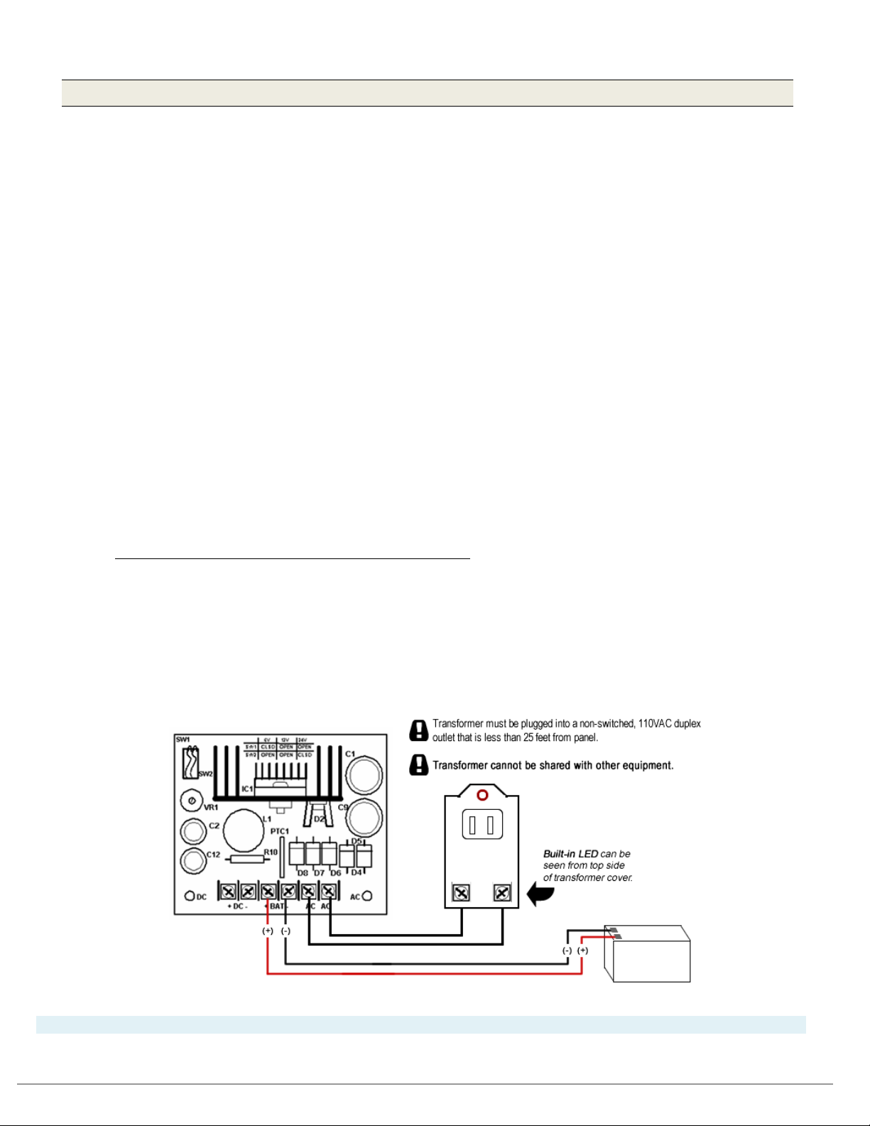
The Galaxy Controller requires a continuous power source from a 110VAC non-switched outlet that is less than
25 feet from the control panel. (Do not connect the power adapter to an outlet that is controlled by a switch.)
AC Power Transformer, Class-2, Plug-in Type (shown with Altronix Power Supply):
The AC Power Transformer, used by Galaxy controllers, must meet following requirements:
• Must be a Class-2 Plug-in Transformer with fused secondary.
• AC Transformer must be plugged into the 110VAC non-switched, duplex outlet.
• Transformer must not be shared by any other equipment.
• Requires 1 pair of 18 AWG wire (minimum).
• Input-rated at 120 VAC / 48 VA at 60 Hz,
• Output-rated 16.5 VAC / 40VA at 60 Hz.
• Must be UL-Listed and CSA-Certified.
Galaxy access control panels that require AC transformers are only intended for use with a UL Listed, Class-2
transformers, like the one manufactured by Universal Power Group No. UB1640WR.
- - - See NEXT PAGE for LifeSafety Power Supply - - -
Chapter-Page 1-4

635/600-SERIES HARDWARE INSTALL GUIDE
Power Supply (LifeSafety FPO75) for Controller (no transformer needed / for US or International):
The LifeSafety FPO75 (75 Watt) Power Supply does not use a plug-in transformer. LifeSafety Power Supply is
compatible for international installations.
CAUTION: Power Input Jumper (JP1) is set 120 VAC/ 60 HZ (Factory Default; i.e. JP1 is closed/not cut).
You must correctly configure the power input JP1 jumper wire – see FlexPower install manual that is shipped
with the power supply. Failure to correctly configure JP1 will cause equipment damage or hazard.
• For 120 VAC / 60 Hz input power = JP1 CLOSED (Factory Default) Do not cut JP1 Jumper Wire.
• For 230 VAC / 50 Hz input power = JP1 OPEN Cut the JP1 Jumper Wire (at red dot).
• Only use 12VDC Output switch position SW1. Galaxy Controllers do not support 24VDC.
1) JP1 - AC Input Voltage Jumper (120/230VAC):
For 120VAC = JP1 is UNCUT (Factory Default)
For 230 VAC = JP1 Wire must be CUT
2) J9 - AC Input Connector (3-prong)
3) LED - AC Power LED (ON/OFF)
4) JP2 - Earth-Ground Jumper (enable/disable) = DISABLED (position 2)
5) JP3 - Battery Jumper (enable/disable) = ENABLED (position 1)
6) J2/J3 - Battery Connections for back up battery (+/-)
7) TB1 - Terminal Block for DC Voltage Output Lugs (DC1)
8) LED - DC Power LED (
9) J1 (or SW1) - DC Output Voltage Jumper = must be set to the 12V position!
Also: SYSTEM FLT LED - Can indicate a missing battery when JP3 is “enabled” and AC power is applied/on.
ON/OFF)
Chapter-Page 1-5

635/600-SERIES HARDWARE INSTALL GUIDE
635 BOARDS
600 BOARDS
OTHER PARTS
20-0635-30
20-0600-60
+3V Lithium Battery: 53-2035-00
20-0235-10
20-0268-40
12V / 8Ah Sealed, Lead-Acid Battery: 90-0714-53
1.4 Hardware Replacement Parts
The 600-series and 635-series Access Control Panels use the following replacement parts:
1.4.1 ORDERING POWER TRANSFORMER & BATTERIES
+3V Lithium Battery – Panasonic CR2354
• Galaxy PN 53-2035-00
• Installs on-board, for the 600-CPU, 635-CPU. Observe polarity when installing.
12V / 8Ah (or equivalent) Sealed, Lead-Acid battery – Universal Power Group UB1280
• Galaxy PN 90-0714-53
• Installs inside the 600- or 635-series controller cabinet.
• Replacement every 3-5 years.
• Do not short-circuit; observing polarity when installing.
• Avoid total discharging (deep discharging).
• WARNING: risk of fire, explosion, or burns. Do not open, disassemble, incinerate or heat above 65°C.
16.5 / 40VA AC Transformer; Class-2 Plug-in - Universal Power Group UB1640RW
• Galaxy PN 90-0714-52
• Input rated 120 VAC / 48 VA at 60 Hz
• Output rated 16.5 VAC / 40VA at 60 Hz
• Must be plugged into a 110VAC, non-switched outlet. Install at distance less than 25 feet from panel.
• DO NOT connect controller power adapter to an outlet that is controlled by a switch.
• Transformer cannot be shared with any other equipment.
1.4.2 ORDERING REPLACEMENT BOARDS
Table 2: REPLACEMENT BOARDS AND PARTS
635 CPU:
635 DPI/DRM:
16.5 / 40VA AC Transformer: 90-0714-52
600 CPU:
600 DPI:
(Class-2 Plug-in)
Chapter-Page 1-6

635/600-SERIES HARDWARE INSTALL GUIDE
1.5 Hardware Capability: Panel-Level (CPU)
1.5.1 Controller Capability of the 600/635 Model Access Control Panel:
TCP/IP (CPU on-board) Ethernet Network Communication:
• 635 MODEL CPU = 10/100 MB / Full Duplex Auto-sensing Ethernet Network capable
(600 Model CPU = 10MB Full Duplex Ethernet Network capable)
• 600/635 models auto-detect/auto-connect to the System Galaxy GCS Event Service after the CPU is
correctly configured for the field settings (provided the Communication Server is installed/online).
• CPUs and daughter boards must be configured* with correct field settings by the installer.
* 635 CPUs have embedded Web Configuration page which is auto-detected when the browser and
CPU are on the same network segment and port 80 is open. All CPUs and daughter boards can be
configured with the Web Configuration Tool or with a terminal emulator such as HyperTerminal.
Some daughter boards use dipswitch and jumpers to set certain features. See Chapter-2.
50,000 card/user capacity/per cluster: expands to unlimited cards if ‘Card Lookup’ feature enabled.
• Supports all card technologies: Prox 125KHz, Barcode, Magnetic Stripe; HID
DESFire™, MIFARE DESFire™ EVI;
®
iClass®; MIFARE®, MIFARE
• Supports Government-compliant Readers/card data: HSPD-12 & FIPS 201; PIV, PIV2, FASC-N 200bit, 75bit
CHUID; TWIC; CAC-Legacy, Transition, Endpoint; PKI challenge to Personal Certificate(PAK)
• Supports Biometric Identification/Authentication Readers: Sagem 2/300, Sagem 100/110, Sagem520;
L-1 Identity (Bioscrypt) 4G-Series Readers; Morpho MA SIGMA (Legacy mode), MA SIGMA 5G Mode*
* SIGMA 5G mode is supported on systems where System Galaxy 10.4.8 (or higher) is integrated
with the MorphoManager/BioBridge software for enrollment of biometric credentials. The SIGMA
reader must be added to the MorphoManager software and the system supports Biometric (finger
only – 1:many) and Prox+Biometric (card+finger – 1:1) . See SG SIGMA with MorphoManager Guide.
Note: SIGMA Legacy mode is supported on SG with the traditional biometric enrollment and does
not depend on MorphoManager or BioBridge module.
254 user-definable Time Schedules per cluster: plus 2 fixed schedules (“Always” and “Never”)
256 user-definable I/O Groups per cluster
256/Unlimited Access Control Groups: 254 user-definable access groups, plus 2 fixed (“Always”/“Never”) and
expands to unlimited with the Personal Doors feature enabled.
10,000-event memory buffer/per CPU (i.e. controller):
NON-DEGRADED OPERATION - Galaxy Panels remain fully operational even when the system or database server is “offline”.
Full functionality is maintained because all users, cards, access rules, schedules and hardware operational settings are stored
in the CPU memory. If the Communication (Event) Server or Database servers are offline, the panel stores its log events in
memory until the CPU is able to reconnect. Upon reconnection, the CPU returns to live event logging and transmits all offline
events to the database. The “offline” events are available via system reports. Any programming changes made at the
software will be stored in the database until the panel comes back online and the data is loaded via the DataLoader service
or GCS Load Utility.
Chapter-Page 1-7

635/600-SERIES HARDWARE INSTALL GUIDE
635 MODEL CPU
600 MODEL CPU
coldstart jack (“park” to warm-reset)
reset switch (1 sec. warm reset/10 sec. cold reset)
RJ-45 Ethernet jack
HFJ-11 Ethernet Jack (Auto-sensing 10/100MB)
Serial Port and programming cable
(option: or use the serial programming port/cable)
635 MODEL DRM
600 MODEL DPI/DRI
(not applicable) install a voltage regulator
if using 5V readers
Board ID is set using CPU RS232 Serial Port (directly
running HyperTerminal® or similar emulator.
Enable/Disable section-2 via SW2
the DRM on an RS485 Multidrop
Power Input terminal for “wet lock
Relays (2 relays each section/port)
“Wet-Lock-Relay” Jumpers to
each section)
1.6 Hardware Capability: Board-Level
1.6.1 List of Boards and Component Descriptions:
This is the list of CPU & Daughter Boards as of System Galaxy v10 Software.
1. CPU Board (600 model & 635 model ) - Central Processing Unit
Supports up to 64 Devices (readers, inputs, etc.) per CPU board/panel
Factory installed 3V lithium backup battery.
Pre-loaded (factory-default) s28 Flash – may require field update to match site system version
9-pin D-Shell, RS232 Serial Port – for configuring CPU with a serial programming cable via Laptop/PC
Table 3: CPU COMPONENTS (635 vs 600)
Configure the IP Address using the RS232
Configure the IP Address using the embedded web tool
2. DPI/DRM Board (600/635) - Dual Port Reader Interface / Dual Reader Module
Supports 2 readers per board
2 surge suppression diodes (to suppress lock surge)
2 supervision resistor/sockets (and 4.7K resistors factory default)
4 Form C SPDT Relays (2 relays each section/port)
SW1 reset switch
Table 4: DRM COMPONENTS (635 vs 600)
12v/5v reader port voltage jumpers
Board ID is set using the SW2 dipswitch
1 RS-485 Communication Port (not applicable)
Dipswitch Option-B; only used for the
RS485 Comm. Port if remotely installing
connecting a PC using a programming cable and
(not applicable)`
relay operation” 4 Form C SPDT
enable/disable the option (for relay-1 on
Chapter-Page 1-8
(not applicable)
(not applicable)

635/600-SERIES HARDWARE INSTALL GUIDE
3. 600 DIO Board - Digital Input / Output Board–
Supports maximum 8 inputs per board
Supports maximum 4 outputs per board
SW1 Reset Switch
4. DSI Board - Dual Serial Port Interface –
2 RS485 Communication Ports per board (Section-1/Section-2)
SW1 Reset Switch
120 K ohm termination resistors included with board (only install resistor near the RS485
connector if the board is at the end-of-line for the 485 Section (channel) you are wiring. Treat each
section independently; one section could be at EOL when the other section is not.
5. 600/635-model Relay Board - for General Output or Elevator Control
Supports 8 outputs per board
Uses Form-A SPST Relays.
RS485 Communication Port (3-pin A/B/GND)
Board ID is addressed via dipswitch
6. 635-model Input Board
Supports 16 Inputs per board (normally open/normally closed must be set in the software screen)
RS485 Communication Port (3-pin A/B/GND)
Termination Jumper (2-pin black) – installer must install jumper only if the board is at the end-of-line.
Voltage / Tamper input terminal provided
Board ID is addressed via dipswitch
Chapter-Page 1-9

635/600-SERIES HARDWARE INSTALL GUIDE
1.7 Hardware & System Descriptions
1.7.1 Description of Galaxy Access Control Panel:
ENCLOSURE DIMENSIONS:
• 18 GAUGE ELECTRICAL CABINET, HINGED
• 8-DOOR/MEDIUM = 18
ADDITIONAL PANEL SIZES OFFERED:
• 2-DOOR/SMALL = 12 X 12 X 4 in.
• 16-DOOR/LARGE = 32
• 8-DOOR/RACK MOUNT = 7
COMPONENTS IN THE DOMESTIC 8-DOOR CONTROLLER :
Factory-installed Power wiring harness for board power (pre-stripped wire tips are
covered with shrink-tubing to prevent shorts)
Factory-installed power supply
harness, with jumpers preset to factory default (see manufacturer’s specifications for your power needs) Additional power supplies may be needed for readers and field devices.
X 13.75 X 6.25 in.
X 13.75 X 6.25 in.
X 19 X 18.75 in. (18 x 49 x 48 c1m) (Std. 4 Rack Units)
(1)
for powering CPU and daughter boards (prewired to
See Power Requirements Section of this guide as well as installation instructions – and the original
manufacturer’s instructions for the reader or device)
Factory-installed tamper switch (prewired to wiring harness)
1 ribbon cable for IC2 Data Bus (with board connectors crimped in place)
1 power transformer 110VAC / 60Hz and AC Cable
1 battery for back up power (12VDC / 8 A-hr – individually wrapped/boxed)
1 pair of battery wires (pre-installed on the power supply)
1 set of keys for the door lock on the enclosure
1 Serial Programming Cable that connects the CPU to a PC Com port for 600 model.
635 CPU and Daughter Boards
* Some Daughter Boards require setting the Board ID and other options using the SW2
dipswitch BEFORE mounting boards inside the enclosure.
Also any on-board jumpers (all models) must be set BEFORE mounting boards.
* are configurable via web interface using port 80.
Note:
CPU & Daughter boards are shipped individually per the Dealer’s purchase order.
NOTE: This list represents a standard, domestic 8-Door Panel. Components may vary for other
domestic and international panels and other sizes
See diagram on next page for example of controller cabinet.
Chapter-Page 1-10

635/600-SERIES HARDWARE INSTALL GUIDE
Figure 1 – 600/635 Model Controller (Access Control Panel) Basic
Chapter-Page 1-11

635/600-SERIES HARDWARE INSTALL GUIDE
1.7.2 635/600-series CPU Description:
See Appendix M for complete list of CPU components
The CPU Board is the brains of the controller and holds the S28 Flash Code in its memory.
635 CPUs are compatible with all 635 and 600 series daughter boards.
• CPU must run the correct version S28 that matches the software (see instructions in chapter 2)
• CPU provides on-board Ethernet (TCP/IP 100 MB full duplex) ; LEDs indicate connection / transmission
• 635 & 600 CPUs provide board programming options via the on board connections via TCP/IP using the Galaxy
Configuration Tool (635) or (RS-232 at J4 (600 only) using HyperTerminal or Putty Tool
• The 635 & 600 CPUs CPU initiate the IP connection to the System Galaxy Event Server.
• 10,000 event buffer per CPU . During operation, the CPU Board processes events locally (at the panel).
Figure 2 – CPU BOARD EDGE COMPONENTS: 635 CPU (Upper) & 600 CPU (Lower)
Chapter-Page 1-12

635/600-SERIES HARDWARE INSTALL GUIDE
voltage regulator in line – preferably at the reader end.
1.7.3 635/600 DRM (DPI) Description:
See Appendix M for complete component list of 600 DPI
The DRM (DPI) Board controls the readers, door contacts, request to exit, door lock, and offers an
additional output relay for both reader/door ports. 600 and 635 DPI’s are interchangeably
compatible with either a 635 or 600-series CPU.
635-DRM WARNING – Do not connect a 5v Reader directly to a 635-DRM. You must install a 5-VDC
635-DRM NOTICE – See Appendix-Q of this guide for installation instructions including wiring
Lock Relays for wet relay operation.
• Controls two (2) Reader ports (sections) per board, including contacts for Door Contacts, REX devices.
• Controls two (2) Lock Relays per board (one relay per reader port/section); Form C SPDT DRY RELAY.
» 600/635 Lock Relays support either Fail-safe or Fail-secure wiring; Dry relay Fail-safe or Fail-
secure wiring is shown in Chapter 2 (see 600 DPI board layout in Appendix M;). All 635 Wet Relay
wiring is shown in Appendix Q).
» 600/635 Lock Relays a support Dry Relay operation by default,
» 635 only supports wet relay operation for Lock Relays; wet/dry operation is independent per
section. See Appendix Q for 635 instructions.
• Controls two (2) Output Relays per board (one relay per port/section); Form C SPDT DRY RELAY. Relay-2
supports either Normally Open or Normally Closed device wiring.
• LEDs are provided on the edge of board to indicate when a Relay is activated (LED = solid on) or deactivated
(LED = off).
1.7.4 600 DIO Detailed Description:
See Appendix M for complete component list of 600 DIO
The DIO Board controls eight (8) input devices and four (4) output devices per board. The board comes with
built-in supervision and Hypervision capability that is turned on from the System Galaxy software after end-
of-line supervision resistors have been installed. The Output Relays are
be wired Normally Open or Normally Closed based on they type of device being used (see diagram of DIO
in Appendix M).
Dry Form-C SPDT relays that can
Chapter-Page 1-13

635/600-SERIES HARDWARE INSTALL GUIDE
1.7.5 600 DSI Description:
See Appendix M for complete component list of 600 DSI
The DSI Board controls two (2) RS-485 serial ports per board for the following devices:
PERIPHERALS
Cypress Clock (Time Clock model 1201)
Galaxy LCD custom message display (displays time and custom messages upon card swipes)
OUTPUT RELAYS
Galaxy Output Relay Board (Elevator Control or General Output Relay control)
WIRELESS READERS
IR Schlage RS-485 PIM for Wireless Readers (Legacy)
Schlage AD300 Hard-wired Readers
Schlage AD400 Wireless Readers
Assa Abloy Aperio Wireless Readers
Salto Salis Wireless Readers
Other wireless readers – see www.galaxysys.com
1.7.6 600 RELAY BOARD Description:
See Appendix M for complete component list of 600 RELAY BOARD
The Relay Board controls eight (8) Form-A SPST relays per board. The board supports General Output control
or Elevator Relay Control. The Relay Board is daisy-chained to the RS-485 port of the DSI board – rules
apply (see Chapter-2 for details; and diagram in Appendix M).
In General Mode, output relays can be triggered by DIO inputs or by certain alarm events (reader &
controller) using I/O Groups (mapped in the software). General relays can also be directly controlled from a
software (i.e. hardware tree, device status, or graphic screen).
Elevator Control mode is also set up in the software after the Relay board have been installed. See
Chapter 2 for hardware installation instructions.
Chapter-Page 1-14

635/600-SERIES HARDWARE INSTALL GUIDE
1.7.7 The System Described:
The hardware side of the system includes controllers (panels) and all field hardware (readers, locks, REXs, etc.) that
make up the access control system. The panels interoperate with the System Galaxy Software by sending
event messages over a LAN/WAN network to the Event Server (i.e. Communication Server/PC). GCS
Services are involved – see figure-2.
The event messages are handled by the GCS Event Service (running on the Event Server) and are logged to the SG
database and SG monitoring software. Core GCS Services are involved in routing the messages properly -
see figure-2. Also see diagram of core services in Chapter 3 Figure 26). The GCS Event Service is described
in Chapter 3 of this manual. GCS Services are explained in-depth Chapter 11 of SG Software Manual.
600-series controllers initiate the connection to the Event Server. The panels are grouped into (assigned to)
Clusters, which are equivalent to a Loop in the software, but there is no primary panel in a cluster. Each panel
initiates its own connection to the Event Server. NOTE: A cluster can be thought of as a TCP/IP loop (or
virtual loop); not a hard-wired 422 loop. A panel can send global events to other panels in the same
loop/cluster.
below for example of global events).
The GCS Event Service must be running to support global events within the cluster (see Figure 1
Figure 3 - Concept Diagram showing how Global Events use the GCS Event Service
Chapter-Page 1-15

635/600-SERIES HARDWARE INSTALL GUIDE
1.7.8 SG System Diagram – Communication/Event Server:
In the diagram (below) you can see how the GCS Services are connected and transmit
messages to the System Galaxy Database and to the System Galaxy Software/Monitoring
screen. Likewise, messages go from the software to the panels via the GCS Services.
Figure 4 - System Diagram of 600-series Loop/Clusters connecting to Event Server
This diagram shows a stand-alone installation (all Software and Services on one server).
Chapter-Page 1-16

635/600-SERIES HARDWARE INSTALL GUIDE
1.7.9 SG System Planning Notes:
While the installer can begin installing the Galaxy Hardware before the software and database are installed,
keep in mind that the SG Database & Communication Server (software/database &GCS services) must be
installed before the panels can connect to the system and be walk-tested.
1. Basic hardware tests can be performed using the Web Configuration Tool / Embedded Web
Page of the CPU before the system walk-through is performed.
2. A full walk-test can be performed after all hardware has been installed, configured and is
programmed into the SG Software/Database, and panels are connected to the GCS Event Service
(system is online).
Tips on Planning an Installation:
1. Obtain and use site plans, blueprints and drawings (as needed).
2. Use the Programming Templates (from Appendix A of this Guide) to record information about the
exact hardware configuration
Helps installer keep track of the hardware during the hardware installation & configuration process
Helps installer correctly identify all hardware during basic hardware tests, troubleshooting & walk-tests
Helps installer correctly configure the hardware into the SG Software/Database
Helps the customer’s IT Administrator understand how to support the Hardware on the LAN/Network
. This information is valuable in the following ways:
3. Determine how many panels and boards you will need to install. .
4. Determine the types and quantity of field devices you will need (readers, locks, contacts, input and
output devices, clocks, separate power supplies, wiring and other field equipment).
5. Determining the Location of controller(s) and field devices. Remember to follow Safety, Mounting,
Wiring and Distance Specifications (see other sections in Chapter 1 for these specifications).
6. Use the correct type of wiring for field devices. Be sure to consider the type of ceiling (plenum vs. non-
plenum). (Reference Chapter 1 Wiring Specifications)
7. Contact the Network Administrator to get network access on the LAN/WAN network.
Chapter 1 – Network Requirements covers LAN network requirements for Galaxy hardware.
Chapter 1 later sections that cover software & system requirements for connecting to Galaxy GCS
Services. This is necessary for logging data to the database and event screen. This information is also
helpful for troubleshooting connections.
Chapter-Page 1-17

635/600-SERIES HARDWARE INSTALL GUIDE
1. First the CPU must be upgraded to the current “stepstone” file version.
3. Finally all daughter boards must be updated to the flash “release” version.
1.8 CPU & Board Flash Requirements for 600/635-Series Hardware
1.8.1 About Factory Flash and Field-Flashing the CPU:
CPU boards come with a pre-installed, factory flash code.
Factory flash allows the boards to start up (boot up) and be configured before they have been field-flashed. This lets
the installer configure network parameters and other settings. The boards must still be field-flashed to the correct
flash version if the factory flash doesn’t match the System Galaxy software, in order to operate correctly.
• IMPORTANT: All CPUs and daughter boards must be running the correct S28 version of flash (i.e. field flash
code) that is compatible with the System Galaxy software operating at the field install site. You may need to
upgrade or downgrade your boards in order to match the system version in a repair scenario.
• IMPORTANT: Field-flashing a controller CPU can be done using the GCS Loader Utility, after configuring the CPU
board settings and IP/network parameters, AND Event Server IP Address.
• NOTE: If the factory flash already matches the field flash version, the installer does not need to flash the board.
NOTICE: When downgrading a factory CPU to older site flash code v5.0 (or older), it is advisable to keep the I2C Ribbon Cable
disconnected from the CPU to prevent daughter boards from prematurely updating to the factory-flash. Reconnect the CPU to the
I2C Bus after the CPU flash has been correctly updated (including validate & burned). See Chapter-2.
IMPORTANT UPGRADE INFORMATION FOR ALL SYSTEMS
A. For systems upgrading from 5.00 Flash or lower - panels must be upgraded in a three-step process:
• If panels are running v5.00 /4.77 Flash (or lower), you cannot go straight up to 10.4.x (or current
flash) – the flash process will not complete, although it will not damage the board. Drop back and run the
“stepstone” file and then run the “release” file.
• Remember: CPU flash version must match the SG Software Version. Reference Flash Version Table in
Chapter 1 or 2 to confirm which flash versions are needed.
2. Then the CPU must be upgraded to the flash “release” file version.
B. For systems upgrading from 5.04 Flash or higher – follow the information below:
• If site is at 5.04 you must disconnect all 635-DSI boards. This does not affect 600 DSI boards.
• This does not affect later versions after 5.04.
• To find out if you have any 635-DSI Boards, send a [Get Board Info] from the Controller Programming
screen in the System Galaxy software (or look up Panel Summary via the CPU’s embedded web page).
1.
First disconnect the 635 DSI’s from the Data ribbon cable.
Upgrade the CPU flash . Then upgrade the other daughter boards as normal.
2.
Finally upgrade each 635-DSI Board individually.
3.
To do this, connect one DSI board to the ribbon cable and upgrade it before connecting and upgrading the
next one. To trigger a flash update, click [Allow Board Flash Update] button in GCS Loader or webpage.
CPU’s and daughter boards can be flashed using the GCS Loader Utility from the System Galaxy software: Launch the GCS Loader Utility
from the software by right-clicking on a loop/cluster name in the Hardware Tree. Use the *_stepstone.s28 and the *_release.s28.
CPU’s and daughter boards can be flashed using the embedded webpage (browser): Launch the panel’s embedded webpage by using the
635 Config Tool or by entering the panel’s IP Address into the browser url. Use the *_stepstone.bin and the *_release.bin. Browser/PC
must be on the same network segment as panel.
SUPPORT: Consult Galaxy Technical Support if you any questions.
Chapter-Page 1-18

635/600-SERIES HARDWARE INSTALL GUIDE
1.8.2 About Auto-Updating the Daughter Boards:
Daughter boards come with a pre-installed factory version of flash code that allows the boards to boot
up even though they have not been field-flashed.
• All daughter boards (DPI, DRM, DIO, DSI) must be running the correct field flash.
• Daughter boards auto-update on the I2C bus (ribbon cable), based on the flash version in the CPU.
• With flash v 5.0 or lower, the CPU imposed a 10-Minute Flash Timer, that delayed the auto-update of
daughter boards for 10-minutes. This timer can be bypassed with the ‘clear auto’ command.
• With flash v 5.04 or higher, the CPU does not impose a 10-Minute Flash Timer. The installer must
manually invoke the flashing of the daughter boards.
WARNING: DO NOT INTERRUPT POWER TO THE PANEL OR TO ANY BOARDS UNTIL ALL BOARDS HAVE COMPLETED
FLASH UPDATES. Interrupting power during flashing can damage the board memory.
1.8.1 Flash Version Compatibility Chart for SG-10:
This section covers Flash Version Compatibility for SG 10/11 and 635-600 Board Compatibility for SG10/11.
Table 5: FLASH VERSION CHART for SG 10/11
SG SOFTWARE FLASH VERSION CPU DPI DIO DSI
(new) SG 11.2.0 Flash v 11.0.3 11.0.3 (all boards)*
SG 10.5.6 Flash v 10.5.6 10.5.6 (all boards)*
SG 10.5.1 Flash v 10.5.3 10.5.3 (all boards)*
SG 10.4.9 Flash v 10.4.15 10.4.15 (all boards)*
SG 10.4.8 Flash v 10.4.8 10.4.8 (all boards)*
SG 10.4.1 Flash v 10.4.1 10.4.1 (all boards)*
SG 10.4 Flash v 10.4 10.4 (all boards) *
SG 10.3.x Flash v 5.04 5.04 (all boards) *
(1)
(1)
(1)
(1)
(1)
(1)
(1)
(1) (2)
SG 10.2.0 Flash v 5.00 5.0 (all boards)
SG 10.1.x Flash v 4.77 4.77 (all boards)
SG 10.0.0 Flash v 4.60 4.60 (all boards)
the new RS485 Input Module or RS485 Door Module are not compatible the 600-CPU.
* -
(1) the CPU no longer uses a 10-min Flash Timer delay. You must manually start daughter board flash updates via GCS
Loader.
(2)
NOTICE FOR 635-DSI Boards (only): To upgrade from 5.04 Intermediate Flash to 10.4 (or higher), you must disconnect all 635-DSI
Boards from the I2C Data Bus – then connect one board at a time and complete the flash update before connecting the next one. This
does not affect the 600 DSI.
SEE THE NEXT TABLE SHOWING BOARD COMPATIBILITY AND SYSTEM VERSION.
See the next page for the Compatibility Charts for SG 10 releases
Chapter-Page 1-19

635/600-SERIES HARDWARE INSTALL GUIDE
635-SERIES CONTROLLER
600-SERIES CONTROLLER
635 CPU Board - Processor
600 CPU Board – Processor
635 DAUGHTER BOARDS
600 DAUGHTER BOARDS
635 DAUGHTER BOARDS
600 DAUGHTER BOARDS
600 DIO Board
600 DIO Board
635 DRM Reader Board
600 DPI Reader Board
635 DRM Reader Board
600 DPI Reader Board
635 DSI Serial Board
600 DSI Serial Board
635 DSI Serial Board
600 DSI Serial Board
Schlage PIM 485 ODT (legacy)
Schlage PIM 485 ODT (legacy)
Schlage PIM 485 ODT (legacy)
Schlage PIM 485 ODT (legacy)
Assa Abloy Aperio (SG 10.1)
Assa Abloy Aperio (SG 10.1)
<< Not supported on 600-CPU
<< Not supported on 600-CPU
Salto Salis Wireless (SG 10.2)
Salto Salis Wireless (SG 10.2)
<< Not supported on 600-CPU
<< Not supported on 600-CPU
or Mix AD-300/AD-400 (10.2)
or Mixed AD-300/AD-400 (10.2)
635 Input Module (SG 10.4)
<< Not supported on 600-DSI
• 635 Remote Door DRM (10.4)
<< Not supported on 600-DSI
COMPATIBLE MODULES (RS-485 multi-drop)
COMPATIBLE MODULES (RS-485 multi-drop)
635 Door Module (using 635 CPU & DSI, SG 10.3)
Table 6: BOARD COMPATIBILITY CHART for SG 10/11 (Tables 7 & 8 for SG-9 or lower )
WHEN IS UPGRADING SG SOFTWARE REQUIRED ?…
if an SG version is noted, then that is the minimum version of SG required to support that board/feature
if the no version is listed, then any version of SG 10 supports the feature.
WHEN IS UPGRADING HARDWARE REQUIRED ?…
Installing Wireless Readers, IP Readers – you must upgrade to 635 CPU and 635-DSI
Installing 635-Input Module – you must upgrade to 635 CPU and 635-DSI
Installing a Galaxy 485 Remote Door Module – You must upgrade to 635-CPU, 635-DRM, and 635-DSI.
Installing newer destination-driven elevator systems, then you must install all 635-model hardware.
• 600-model boards can interoperate with 635-model boards in the same system and within the same control panel.
• You can replace older 600-model boards with new 635-model boards as needed.
• The older 600-model boards do not support the newer hardware interfaces and features supported by the 635.
• Operates in same loop /system with 600 CPUs
• Supports all 635 & 600 daughter boards
• Supports all 635-series RS 485 Modules
• Supports all 600-series RS 485 Modules – restrictions apply*
• Supports Destination-driven elevator systems
• Supports Card Tour Board
• 600 Output Module (general
output or elevator control)
• LCD Clock unit
•
•
•
• Schlage AD-300 (SG 10.2)
• Schlage AD-400 Wifi (10.2)
•
• Assa IP Readers (SG 10.4) • Assa IP Readers (SG 10.4)
•
• 600 Output Module (general
output or elevator control)
• LCD Clock unit
•
•
•
• Schlage AD-300 (SG 10.2)
• Schlage AD-400 Wifi (10.2)
•
• Operates in same loop /system with 635 CPUs
• Compatible/Supports all 600 daughter boards
• Supports 635 DRM (Reader board)
• Supports 600 Output/Elevator Modules on 600 DSI
• Destination-driven elevator systems and Card Tour are not supported.
• 600 Output Module (general
output or elevator control)
• LCD Clock unit
•
• 600 Output Module (general
output or elevator control)
• LCD Clock unit
•
600 Elevator/Output Module ( using DSI )
Chapter-Page 1-20
635 Input Module (using 635 CPU & DSI, SG 10.4) << 635 Input Module not supported on 600 CPU
<< 635 Door Module not supported on 600 CPU
600 Elevator/Output Module ( using DSI )

635/600-SERIES HARDWARE INSTALL GUIDE
FLASH VERSION
CPU
DPI
DIO
DSI
SOFTWARE VERSION
V4.57 Flash
4.57
4.57
4.57
4.57
SG 9.0.5
V4.51 Flash
4.51
4.51
4.51
4.51
SG 9.0.4
V4.50 Flash
4.50
4.50
4.50
4.50
SG 9.0.0
V2.30e Flash
2.30e
1.71d
1.61b
2.31f
SG 8.3.0
v1.74d Flash
1.74d
1.60h
1.40b
2.12a
SG 8.2.3
v1.60 Flash
1.61j
1.60e
1.40b
2.2b
SG 8.2.2
v1.60 Flash
1.60n
1.60e
1.40b
2.2b
SG 8.2.0
v1.40 Flash
1.40d
1.40c
1.40c
not used
SG 8.1.1
to a recent version of SG 10 or 11. Contact Technical Support for assistance.
Software Compatibility
Hardware Compatibility
Factory Revisions
Board
1.8.2 Older Flash Version Compatibility Charts (SG-9 / SG-8):
Table 7: FLASH VERSION CHART for SG-9 (and older)
IMPORTANT: you may need to step up the flash to interim versions to make the upgrade all the way
Table 8: SG 9/8 Software Compatibility for 600-series Board Revisions
SG Software S28 Flash
SG 9.X
SG 8.X
See Table above
for correct Flash
Version
(1)
600 CPU Board - Processor Board
Board Models
(A, B, C … E, F, etc.)
All CPU revisions are compatible with all
daughter-board revisions.
600 DIO Board - Input/Output Board
600 DPI Board - Reader Interface
All daughter-board revisions are compatible
with all CPU revisions.
600 DSI Board - RS-485 Serial Board
(1) All CPUs and daughter boards should be running the correct flash code that was released with the SG Software that is installed
on the jobsite. Find the correct flash version by opening the software help window or by opening the Loader Utility. If you replace
a board you must flash it to the correct version issued with the installed SG version. If you upgrade the SG Software system, then
you must reflash all your panels and daughterboards to the version of flash that is issued with the new SG Software. The flash
running in the panel/boards must be in sync with the SG Software version installed. Obey any stepped upgrade flashing
instructions mentioned in the prior section. Always contact Tech Support to ensure you have the complete information for
upgrading flash.
Chapter-Page 1-21

635/600-SERIES HARDWARE INSTALL GUIDE
1.9 Controller Mounting Requirements
1. The controller enclosure must be wall mounted using tear-drop shaped mounting holes.
2. Panel can be mounted horizontally (typical) or vertically
Non-condensable: do not mount in or near water, liquid, moisture or rain/weather
Clean, reasonably dust-free environment.
Temperature should be between -10° C and +60° C.
Location should have limited access for security purposes.
Do not mount to metal studs or brackets.
Do not connect Chassis to Cold Water Ground.
Avoid power transformers and high voltage and high frequency devices.
Figure 5 – 6XX-Series Controller Mounting Requirements:
Applies to both 635- and 600- model controllers. Medium controller shown.
Chapter-Page 1-22

635/600-SERIES HARDWARE INSTALL GUIDE
Figure 6 – 6xx-series Medium Controller Dimensions & Knockout Diagram:
This diagram shows a facing (inside) view of the back and inside views of sides for a medium
controller enclosure.
Drawing is shown rotated 90 degrees to fit on page.
Dimensions shown in inches.
Chapter-Page 1-23

635/600-SERIES HARDWARE INSTALL GUIDE
1.10 Power Requirements
1. A Power Transformer 16VAC @ 40 VA (transformer included if purchased with panels).
• Power transformer must be plugged into a 110VAC/60Hz outlet that is less than 25 feet from the
controller.
• The 110VAC outlet cannot be controlled by a switch.
• Transformer cannot be shared with other equipment.
2. The controller comes with a 12VDC 2.5 amps Power Supply for powering CPU and daughter boards (power
supply included as purchased with panel).
The 12 VDC Power Supply must be connected to the controller’s wiring harness inside the panel by the
installation technician.
3. Do not power relay boards on the same power supply as CPU, DPI or DSI. If 635/600 Model Output or
Elevator Relay Boards are in the same panel with a CPU and DSI, they will need a separate power supply;
Output Rated at 12 VDC 2.5 amps.
4. When using more than four proximity readers on one controller, it is necessary to use an additional power
supply to power the additional readers. You must common the grounds between the power supplies in the
panel (readers only).
5. When using biometric readers: biometric readers must be powered separately. Do not power Biometric
readers from the DRM board or from the controller power supply.
6. Powering door locks: An additional DC Power Supply is required. Do not power door locks from the DRM
board or from the controller power supply.
7. IMPORTANT: Do NOT use the same power supply for Locks and Readers. Use a separate power supply for
locks.
8. IMPORTANT: additional power supplies must be purchased for any field devices or equipment that will
require it (e.g. Sagem Readers, Cypress Clocks, input or output devices, etc.). Follow the device manufacturer’s
guidelines for type of power supply to use.
9. IMPORTANT: DO NOT Common the Ground of the Lock Power to the controller power supply or to the
reader power supplies.
10. Surge Suppression Diodes should be installed parallel to lock to suppress kickback surge. Diodes should be
located at the lock and as far away from the controller as possible.
Chapter-Page 1-24

635/600-SERIES HARDWARE INSTALL GUIDE
Board
Relay Type
Port Output =
See Appendix Q for details.
Output Control
Control
Current draw for a single board
Current draw with relays energized
CPU = 0.07 amps (70 mA)
n/a
DPI / DRM= 0.03 amps (30 mA)
0.25 amps (250 mA) with 2 HID ProxPro readers and all 4 relays energized.
DIO = 0.05 amps (50 mA)
0.15 amps (150 mA) with all 4 relays energized
Relay Board = 0.02 amps (20 mA)
0.60 amps (600 mA) with all 8 relays energized.
DSI = 0.02 amps (20 mA)
n/a
Ex: one Controller with 1 CPU, 1 DPI, 2 Prox Readers and all 4 relays energized will draw 0.350 amps.
1.11 Relay Ratings and Current Draw
The following tables show Relay Ratings and the Current Draw with and without relays energized.
Table 9: Ratings for Relays for Galaxy Hardware
635 DRM Reader Board
600 DPI Reader Board DRY Form-C SPDT Relays
600 DIO Board DRY Form-C SPDT Relays
600 Output Relay Board
Elevator Control or General
635 Output Relay Board
Elevator & General Output
Form-C SPDT Relays
supprots “dry” or “wet”
contact relay operation.
Supports dry contact only.
DRY Form-A SPST (NO) 24 VDC @ 1.5 amps maximum per relay.
DRY Form-C SPDT
Support NO and NC wiring.
24 VDC @ 1.5 amps maximum per relay.
24 VDC @ 1.5 amps maximum per relay.
24 VDC @ 1.5 amps maximum per relay.
Requires a separate power supply.
24 VDC @ 1.5 amps maximum per relay.
Requires a separate power supply.
Table 10: Board Current Draw for Galaxy Hardware
Chapter-Page 1-25

635/600-SERIES HARDWARE INSTALL GUIDE
Connection Type
Max Distance
Wire Gauge & Specifications
Reader Hardware
SIGMA Reader
Lock Hardware
Composite Cable
RS-485 NODE/PIM/DRM
*
635 Input Relay Board
*
Use Plenum-rated cable when appropriate
Connection Type
Max Distance
Wire Specifications
1.12 Hardware Wiring Specifications
1.12.1 Controller Ethernet Communications:
635 CPU = Auto-sensing 10/100 Mb /Full Duplex at the port side.
600 CPU = 10 Mb Ethernet/Full Duplex at the port side.
1.12.2 Hardware Wiring Specifications (Type, Gauge, Distance):
Table 11: DEVICE WIRING SPECIFICATIONS
500 ft. from controller 22 AWG, 10-conductor, stranded / shielded
500 ft. from controller 20-24 AWG, single-conductor, non-stranded / shielded
500 ft. from controller 18 AWG 2-conductor minimum, stranded
500 ft. from controller 18 AWG & 22 AWG Card Access 4-Element
4,000 ft to last node
4,000 ft to last node
* total line distance from a DSI Board to the last device/node (e.g. PIM, DRM.) on the multi-drop = 4,000 ft max
WARNING! Observe Fire and Electrical Codes for wire insulation jackets (i.e. PVC-rated vs. Plenum-rated).
22 AWG, shielded, twisted pair
22 AWG, shielded, twisted pair
Table 12: ETHERNET WIRING SPECIFICATIONS
Controller to IP Switch: 100 meters (328 ft.) Cat 5e Unshielded, twisted-pair (UTP)
(TCP/IP)
port to port on local LAN side
SUPPORT: Consult Galaxy Technical Support if you any questions.
IMPORTANT: Use the correct Cat5e unshielded twisted-pair cable. Always use best industry practices.
IMPORTANT: All maximum distance limits are estimates based on clear/unimpaired communication. If interference
exists, wiring should be rerouted to get clear communication. Failure to correct installation issues will
result in undesired hardware/system operation.
IMPORTANT: Use overall shielded wiring for all device wiring.
Failure to use overall shielded wiring may result in equipment operating poorly or incorrectly. If a
site has not used proper wiring techniques, you may need to install new wiring.
IMPORTANT: Properly ground the DRAIN WIRE of the shielded cable:
Connect the drain wire to the negative on the board (GND) or to the negative DC Terminal of
the power supply. NEVER ground the drain wire at a Reader (or device-end of the wire-run.
Failure to properly ground the drain wire will result in undesired equipment operation
Chapter-Page 1-26

635/600-SERIES HARDWARE INSTALL GUIDE
See
or information on how to use the tool to configure and test the controller, boards
and communication ports.
1.13 Board Programming Requirements
1. 635- model boards can be configured using the Galaxy 635 Web Configuration Tool.
The 635 Web Tool opens in a standard Web Browser. The Tool automatically finds all Galaxy CPUs by their
MAC address, provided the panels are online/on the same network segment as the Web Tool – and provided
the controller cabinet door is open (tamper switch open).
OPTIONALLY: If the installer cannot access the network/segment and connect to the 635-model boards via the
Web Tool, the installer can connect directly to the boards via the RS-232 Programming Port using a Standard Serial
Programming Cable. In this method, the installer uses a Terminal Emulator (i.e. Putty, HyperTerminal
connect to the panel CPU - and program the 635-CPU Network IP Settings, Cluster ID, Controller Unit ID, and GCS
Event Server IP Address, as well as other CPU options. Be aware all 635-Model Daughter Boards have a dipswitch
to configure the Board ID and other options. [600-model CPUs and Daughter Boards can also be programmed via
the Terminal Emulator].
The RS-232 Programming Serial Cable comes with controller enclosure:
• Cable Pin-out must be: Pin 2 to Pin 2, Pin 3 to Pin 3, Pin 5 to Pin 5.
• The cable must have a DB9 female connector on one end and a DB9 male connector
on the other end
• Connect the programming serial cable to the J4 serial port on the CPU Board and the
standard 9-pin serial port on the PC or laptop that is running a Terminal Emulator.
®
, etc.) to
Putty / Terminal Emulator Session parameters:
BAUD Bits per Second = 57,600 K BPS
Parity = None
Data Bits = 8
Stop Bits = 1
Flow Control = None
the Web Configuration Tool Guide f
2. Each Controller must have a unique Unit ID number within the Loop/Cluster (see Figure 6).
3. The CPU Board ID is “0” by default – this value cannot be changed.
4. The CPU Number should be set to “1”. If a second (dual) CPU board is installed, its CPU number
should be set to “2”.
5. All daughter boards (DPI, DIO, DSI, etc.) must have a unique Board ID within their Unit
(controller/panel). Board numbers 1 through 16 are valid for each controller.
The 635 DPI must be addressed to a unique binary value on the controller bus using the on-board dip switch located on the
back edge of the board. The 635 DPI is compatible with either 635 or 600 CPU and can coexist with 600 DPIs, DIO, DSI.
6. Unique/Valid IP Addresses must be used for 6xx-series controllers. The CPU can have a static
IP Address or non-routable IP Address. 6xx-series also supports DHCP Addressing; however, it is
not recommended for the stability of the Access Control System. Note: a static IP Address cannot be
blank or zeros. You must program a private IP address even if using the DHCP.
7. The controllers communicate with the Event Server on port 3001. Port 3001 must be open and
unblocked at firewalls, routers and switches, etc. for communications to occur.
NOTICE: The 6xx-series board settings must match the software programming for proper operation (see Figure 6).
Hardware is usually installed and configured before the software. If the software is already programmed, you must
use the Loop, Unit, and Board ID’s set in the software – these settings are found in the Loop and Controller
Properties screens. TIP: Use Hardware Programming Templates from Appendix A (which can be copied as
needed) to record panel settings and locations for use when the software is being programmed.
Chapter-Page 1-27

635/600-SERIES HARDWARE INSTALL GUIDE
Figure 7 – 600/635-Model Controller Configuration Example:
This example shows of how the Controllers/CPUs are grouped into Loop/Clusters and configured
connect to the System Galaxy Event Service using the TCP/IP Ethernet network (LAN/WAN).
Every 600/635-Model Controller (CPU) is assigned a unique/valid Loop/Cluster ID (i.e. 1, 2, 3 …).
Each Control Panel CPU is assigned a unique/valid Unit ID (1, 2, 3 …) within its loop/cluster.
Each Daughter Board (DPI/DRM, DIO, DSI) is given a unique/valid Board ID (1, 2, 3 …) within its panel.
NOTE: Software programming must match exactly to the configuration of the hardware (see Appendix for Templates to
record your actual CPU and Board configuration as you install. This helps you keep track when programming software.
NOTE: See Chapter-2 for step-by-step instructions for the CPU and Board configuration.
NOTICE: The panels behave as if they are on the same loop/cluster based on the assigned Loop/Cluster ID. Each
controller/panel connects to the SG Communication/Event Server using the TCP/IP Ethernet network. The SG Software
will identify and treat the panels as being on the same Loop/Cluster when logging events, issuing loop-level commands,
and loading/managing system configuration, (i.e. adding/deleting cards, managing access privileges, schedules, etc.).
Chapter-Page 1-28

635/600-SERIES HARDWARE INSTALL GUIDE
1.14 Network & IT Requirements for Galaxy Hardware
This section lists requirements that pertain to System Environment, Networking and IT Requirements.
Galaxy Hardware is designed to communicate over TCP/IP connections/networks with the following stipulations.
1. Unique, static or non-routable IP Addresses must be given to each Galaxy Panel (CPU) and the
computers that host the GCS Communication and Event Services.
If private IP Addresses are not available, a non-routable IP Address should be used.
NOTICE: If DHCP addressing is used, and the DHCP server goes offline or changes the addresses, then
connectivity between the server and loops will be adversely affected!
2. 635 Controller: TCP/IP over LAN/WAN 10/100 Mb Ethernet/Full Duplex at port side.
3.
Specific port numbers must be available and not blocked by firewalls, switches, or routers. System
Galaxy uses port numbers 1433, 5010, 3001, 4000, 4001, 4002, and 4003
4. Windows OS need to set PC firewall at the Communication Server to accept the File and Print Sharing,
sqlservr.exe and sqlbrowser.exe.
.
5. ONLINE VS. OFFLINE OPERATION: An access control system should have a stable network
environment.
a. OFFLINE OPERATION: Controllers are designed to operate independently (offline) in a non-degraded mode of
operation when the software/database/services are offline. All “offline events” are buffered in the panel memory if
the server connection is interrupted. Offline events in the buffer are retransmitted when connections to the
Services and Database are restored.
b. REAL-TIME EVENT MONITORING: If your customer is providing real-time event monitoring, the panels will need
reliable/uninterrupted network connection to the SG Server/services, SG software & database. The following GCS
Services must be running/online for real-time events. GCS Client Gateway, GCS Communication Service, GCS
Event Service, GCS DBWriter Service typically are hosted on the main Communication Server. A copy of the GCS
Client Gateway must also be running on every additional monitoring station. The MSSQL Service typically runs on
the Database server (where the database is installed. This can be on the same machine (standalone install) that
serves as a communication server for small systems. On larger systems the Database server is often a separate
machine from the Communication server.
c. Avoid running the Galaxy Hardware and Software on a network that is unstable, subject to frequent
downtime or heavy network resource demands. Networks that provide email or public internet use can become
bogged down with traffic. Consider a dedicated network (such as one with non-routable addressing), especially if
you are using real-time event monitoring, alarm event monitoring, time & attendance, or input/output logic that
requires global events (panel to panel).
d. Add all System Galaxy programs and services to any firewall, network scanning, or port blocking software.
Logging of events, and real-time monitoring can be adversely affected.
6. LOCATION OF SERVICES AND PANELS:
• LOCATION OF SERVICES: Typically, the GCS Event and GCS Communication services are running on the same
computer in the same time-zone as the panels.
• MULTIPLE EVENT SERVERS: The system can support multiple copies of the GCS Event service but they must run on
separate computers. You cannot have multiple copies of the Event service on the same computer or vm.
• REMOTE PANELS AND MULTIPLE TIME-ZONES: In cases where the system is large or panels are distributed across
a wide area – (e.g. a campus setting, or remote buildings), any panels that are in a different time-zone will require a
separate copy of the Event Service running on a separate computer that is configured to use the time-zone of the
remote panels. The separate computer can be physically located in the remote time-zone, but better practice may be to
have the computer in the local time-zone. The computer serving the remote panels must be configured to the same
time-zone as the remote panels. This allows the remote events to maintain their original time-stamp.
Chapter-Page 1-29

635/600-SERIES HARDWARE INSTALL GUIDE
1.15 Communication Requirements for System Galaxy Servers
This section covers info about System Galaxy services, which affect logging events from the hardware.
EVENT HANDLING (MONITORING VS. LOGGING EVENTS)
1. When the SG Software is installed, typically the core GCS Services are installed on the same machine (GCS
Client Gateway Service, GCS Communication Service, GCS Event Service, GCS DB Writer Service).
NEEDED TO
Name of Services
GCS Client Gateway Service YES NO Converts binary data to man-readable messages.
GCS Communication Service YES YES Sends binary data to Gateway and DBWriter. Initiates
GCS Event Service YES YES 635/600-series panels initiate their connection to the Event
GCS DB Writer Service YES YES Logs binary data to SQL Server / SG Database.
MONITOR ?
NEEDED TO
LOG EVENTS ? MAIN PURPOSE OF THE SERVICE
connection to the Event Service.
service based on the IP Address.
2. LOGGING AND MONITORING REQUIREMENTS:
The 635/600-series hardware is designed to continue functioning in a non-degraded operation, for panel-level operations
and access decisions, without the System Galaxy client software or database being online.
Off-line Events are buffered in the controller’s memory and retransmitted to the Database and Monitoring workstation
when connectivity is restored. NOTE: The core GCS Services must be running and able to establish ODBC and IP
connections in order for events to be logged to the Database and the Client Monitoring workstation.
A Local Event is defined as an event that happens at a panel (such as an input) and triggers an output at the same panel
in the same loop/cluster. Local events are not interrupted if Event Service/Server is down.
A Global Event is defined as an event that happens at one panel (such as an input) and triggers an output at a different
panel in the same loop/cluster (i.e. panel-to-panel). Global events are interrupted if the Event Service/Server is down. By
design the Event Service can continue operating if the database or the software is off-line – as long as the host PC is
running/online.
RUNNING
MULTIPLE EVENT SERVERS ( INCLUDING TIME-ZONE OPERATION )
3. You can run multiple GCS Services as long as they are on separate PCs/Servers. You cannot run
multiple copies of the GCS Service on the same machine (PC, Server, Virtual Machine). The same is
true for the GCS Communication Service.
a. If you are running multiple Event Servers, you CANNOT split a loop/cluster. All the 635/600-series
controllers that are in the same loop must be assigned to the same GCS Event Server. Multiple
loops/clusters can be assigned to the same cluster.
b. You cannot split the controllers in a loop/cluster between multiple servers.
c. All panels in the same loop must be assigned to the same IP Address where the GCS Service is
running.
4. If you have remote panels that are installed in a different time-zone than your central system, you
must run multiple Event Services on a separate PCs or VMs to serve the local & remote panels.
a. The “Local” GCS Event Service (serving the local panels) will run on a PC/VM that is physically located in
your local time-zone. This PC must have its clock set to your local time-zone.
b. The “Remote” Event Service (serving the remote panels) must be running on a separate PC/VM. This PC
can be physically located in the local time-zone, but it must have its clock set to run the same remote timezone that the remote panels are in. This allows the events from the remote panel to be logged with the correct
time stamp.
Chapter-Page 1-30

635/600-SERIES HARDWARE INSTALL GUIDE
1.16 Requirements for Logins and User Privileges (SG Software)
1. You must have Administrator Rights In order to install System Galaxy Software.
2. Operator/User must log in as a’ power user’ in order to program hardware in the System Galaxy software.
3. The System Galaxy software must be able to connect to the database in order for the operator to log in and
start the SG software. This means the core GCS services must be running and connected to the database.
4. SG Operator Login Privileges can affect the ability to see events in the monitoring screens or use certain
features and commands in the System Galaxy software.
5. System Galaxy software has a 14-day Registration grace period for the System and the Workstation.
This grace period starts from the date the software is installed. If the grace period lapses before the software
is properly registered, features and monitoring are affected. Contact your Dealer/Tech Support for assistance
with Registration.
1.17 Pinout for Ethernet Cable (Cat-5e)
THIS DIAGRAM SHOWS HOW TO MAKE A NETWORK ETHERNET CABLE (CAT-5e)
Chapter-Page 1-31

635/600-SERIES HARDWARE INSTALL GUIDE
1.18 General FAQs about Features of Galaxy Hardware
System Galaxy 10 software allows both 508i Loops and 635/600 Loops at the same site; however
the 508i and 600 panels cannot be mixed into the same loop.
The 635/600-series Controller does not communicate with 508i controllers or 508i loops.
The 635/600-series Controller communicates with other 635/600-series Controllers that are in the
same loop/cluster provided the Event Service is online. This is known as global event traffic (or panel-
to-panel communication) - supports functionality like pass-back, door interlock, Inputs & Outputs (I/O), etc.
635/600-series Controllers cannot pass events to panels that are in a different Loop/cluster.
600-series Panels communicate using TCP/IP with 10 MB/Full Duplex.
635-series Panels communicate using TCP/IP with 100 MB/Full Duplex.
The 600 DPI-Reader board interfaces with current reader technologies supported by System Galaxy.
Each board supports 2 readers; a lock relay and 2nd relay for both readers (4 relays total).
635 DPIs are cross-compatible with all other boards. 635 DPIs additionally offer wet-lock relay
operation – see the Appendix for 635 Wiring to see this.
The 600 DIO board has 8 max inputs and 4 max outputs.
The 600 DIO board supports Supervised inputs (e.g. series (in-line), parallel (end of line), or series-
parallel resisters). Once the resisters are installed the feature is programmed in the Inputs Properties
screen, which offers the common industry standard resistor values.
The 600 DIO board supports HYPERVISION, which is an added layer of supervision to prohibit
supervised circuits from being defeated. Hypervision is enabled via the software programming screen.
The 600 DSI board supports Cypress clock on RS-485 channel.
The 600 DSI board supports Schlage Wireless™ Access PIM-485 on the RS-485 channel.
The 600 DSI board supports the 600 Relay board on the RS-485 port. The relay boards can be daisy-
chained and limits apply based on whether they are used for general output or elevators.
The 600 Relay boards support General Output and Elevator Control.
Chapter-Page 1-32

635-SERIES HARDWARE MANUAL
IMPORTANT: Each STEP of the install instructions should be performed in sequence. Each step is
steps out of sequence will result in an improper installation and system failure.
!
!
STEP 1. Hardware Install ~ Site Preparation ........................................................... 2-5
6.1 Connecting to the CPU Board via Putty® or HyperTerminal® ............................................ 2-54
2. Hardware Installation Instructions
!
dependent upon the previous step. Each step must be completed correctly. Skipping steps or doing
IMPORTANT: The main instructions have been updated for the 635-model Boards. 600-model
information is found in an older guide or in the appendices of this guide.
IMPORTANT: The older 600-model boards are still compatible with the newer 635-model boards,
however 600-models do not support newer features. See Step-1 for board capability.
HARDWARE INSTALL STEPS ~ Quick List:
1.1 Conducting a Site Survey .......................................................................................................... 2-5
1.2 Requirements and Safeguards ................................................................................................. 2-7
1.3 About Upgrading Hardware / Expanding Systems ................................................................. 2-9
1.4 Board Compatibility and Capability (635 vs. 600 models) ................................................... 2-10
STEP 2. Mount the Controller Enclosure/Cabinet ................................................. 2-11
2.1 Choose a good location for the Controller ............................................................................ 2-11
2.2 Running Field Wiring ............................................................................................................... 2-12
2.3 Mount the Controller Cabinet .................................................................................................. 2-13
STEP 3. Install Power Connectors inside Controller ............................................ 2-14
3.1 Remove Heat Shrink (only from wires to be used) ............................................................... 2-14
3.2 Wire the CPU Power Connector and Tamper Switch ........................................................... 2-15
3.3 Wire the “A/C Fail” and “Low Battery” to Sense Connector ............................................... 2-16
3.4 Wire the Power Connectors for the Boards (DRM, DIO, or DSI) .......................................... 2-17
STEP 4. Install the CPU and Interface Boards (daughter boards) ....................... 2-18
4.1 Install the 635-CPU Board inside Controller .......................................................................... 2-18
4.2 Installing a 635-DRM Board (Dual Reader Module)............................................................... 2-19
4.3 Install the DIO Board in the Controller ................................................................................... 2-25
4.4 Installing a 635 DSI Board (Dual Serial Interface) ................................................................. 2-27
4.5 Installing a 635-Model Output Relay Board ........................................................................... 2-35
4.6 Installing 635-Model Input Module ......................................................................................... 2-43
STEP 5. Applying Power to the Controller ............................................................. 2-52
5.1 Pull all field wiring into the controller .................................................................................... 2-52
5.2 Connecting Back-up Battery and Power Transformer to the Power Supply ..................... 2-52
5.3 About adding an Auxiliary Power Supply inside the Controller......................................... 2-53
5.4 About External Power Supplies outside the Controller ....................................................... 2-53
5.5 Installing Suppression Diodes at the Door Locks ................................................................ 2-53
STEP 6. Program the 635 CPU Board ..................................................................... 2-54
Chapter-Page 2-1

635-SERIES HARDWARE MANUAL
About walk-testing hardware: Some software set up is required to test hardware. Brief
instructions are found in this manual to help you set up the software.
6.1 Programming the 635-Model CPU Board via Web Page ...................................................... 2-55
STEP 7. Set the Interface Board ID’s (DPI/DIO/DSI) ............................................. 2-60
7.1 Apply power to the “Daughter” Boards (DPI/DIO/DSI) ......................................................... 2-60
7.2 Verify Board ID is Correct for Daughter Board(s) (DRM/DIO/DSI) ....................................... 2-61
7.3 Verify Flash Version is Correct for Daughter Board(s) (DRM/DIO/DSI) .............................. 2-61
7.4 Flash Version Chart ................................................................................................................. 2-62
STEP 8. Connect the Controller CPU to the Network ........................................... 2-63
8.1 Connect the CPU to the Ethernet LAN ................................................................................... 2-63
8.2 Verify Connection to the Event Server ................................................................................... 2-64
STEP 9. Test the Controller (recommended) ......................................................... 2-66
9.1 SOFTWARE PROGRAMMING QUICK NOTES: ...................................................................... 2-66
9.2 TESTING PANELS with WEB PAGE OR SOFTWARE COMMANDS: ................................... 2-66
STEP 10. Wiring Field Devices to all Interface Boards ........................................... 2-67
10.1 Field Wiring Standard Readers to the 635 DRM Board ...................................................... 2-68
10.2 Field Wiring the SIGMA Morpho to the 635 DRM ................................................................ 2-70
10.3 Field Wiring the 635 DRM for ANTI PASSBACK................................................................. 2-71
10.4 Field Wiring the DIO - Digital Input/Output board ............................................................... 2-72
10.5 About setting up Supervision & Hypervision of Inputs ..................................................... 2-73
10.6 Field Wiring the 635-Input Modules to the 635-DSI Board ................................................. 2-75
10.7 Field Wiring Output Relay Boards to the 635-DSI Board ................................................... 2-76
10.7 Field Wiring Schlage AD PIMs to the 635-DSI Board .......................................................... 2-77
10.8 Field Wiring 635-DRM Remote Door Module to the 635 DSI Multidrop ............................ 2-78
10.9 Field Wiring Cypress Clock to 635-DSI Board..................................................................... 2-79
10.10 Field Wiring LCD Display Unit to 635-DSI Board - ............................................................ 2-80
STEP 11. Walk-Test the System (recommended) .................................................... 2-81
11.1 Quick Steps to Software Setup ............................................................................................. 2-81
11.2 Quick Steps to creating a Test Card .................................................................................... 2-82
LIST OF TABLES IN THIS CHAPTER
Table 13: WIRING SPECIFICATIONS ........................................................................................................................ 2-8
Table 14: BOARD COMPATIBILITY CHART for SG10 .......................................................................................... 2-10
Table 15: 635-CPU PINOUT ..................................................................................................................................... 2-15
Table 16: DRY-CONTACT RELAY OPERATION = (NORMAL OPERATION) ....................................................... 2-22
Table 17: WET-CONTACT RELAY OPERATION = JUMPERS INSTALLED ......................................................... 2-22
Table 18: BINARY ADDRESS TABLE FOR 635-DRM ............................................................................................ 2-23
Table 19: DSI Max. Number of Devices and Device Count for each Section ..................................................... 2-29
Table 20: Examples of DSI Sections Functioning Independently ....................................................................... 2-30
Table 21: Mapping the DSI “Section Use” in the SG Software............................................................................ 2-30
Chapter-Page 2-2

635-SERIES HARDWARE MANUAL
Table 22: SET THE TERMINATION JUMPERS FOR EACH SECTION ................................................................. 2-31
Table 23: SET THE PASS-THRU JUMPERS FOR EACH SECTION ..................................................................... 2-32
Table 24: BINARY ADDRESS TABLE FOR 635-DRM ............................................................................................ 2-33
Table 25: BINARY ADDRESS TABLE FOR OUTPUT RELAY BOARD ................................................................. 2-38
Table 26: WIRING PINOUT FROM 635-DSI TO FIRST RELAY BOARD ............................................................... 2-42
Table 27: WIRING PINOUT FROM ONE RELAY BOARD TO NEXT RELAY BOARD .......................................... 2-42
Table 28: BINARY DIPSWITCH SETTINGS FOR INPUT BOARD ......................................................................... 2-46
Table 29: WIRING PINOUT FROM THE 635-DSI TO FIRST INPUT BOARD ........................................................ 2-51
Table 30: WIRING PINOUT FROM ONE INPUT BOARD TO NEXT INPUT BOARD ............................................. 2-51
Table 31: FLASH VERISON CHART ....................................................................................................................... 2-62
Table 32: WIRING DISTANCES FOR HARDWARE ................................................................................................ 2-67
Table 33: Software Setup - Process for 600 Loops are as follows ..................................................................... 2-81
LIST OF FIGURES FOUND IN THIS CHAPTER
Figure 8 – Illustration of UL-Listed Power Supply and Transformer .................................................................... 2-6
Figure 9 – 6xx-series Controller Mounting Diagram ............................................................................................ 2-13
Figure 10 – Controller Wiring Harness: ................................................................................................................. 2-14
Figure 11 – Diagram of CPU Power and Tamper Connectors: ............................................................................ 2-15
Figure 12 – 635 CPU Warning Circuits: “A/C Fail”, “Low Battery”, and “Tamper”........................................... 2-16
Figure 13 – Wiring Power Connector on 635 DRM: .............................................................................................. 2-17
Figure 14 – Installing CPU (with bracket against back of cabinet) ..................................................................... 2-18
Figure 15 – 635 DRM Board Features: ................................................................................................................... 2-19
Figure 16 – BINARY DIPSWITCH for DRM Board ID ............................................................................................ 2-23
Figure 17 – Installing a DRM Board with bracket against back of cabinet: ....................................................... 2-24
Figure 18 – 600 DIO Board Features: ..................................................................................................................... 2-25
Figure 19 – Installing a DIO Board with bracket against back of cabinet: ......................................................... 2-26
Figure 20 – 635 DSI Board Features: ..................................................................................................................... 2-27
Figure 21 – Examples using Termination Resistance with the 635 DSI Board: ................................................ 2-31
Figure 22 – Using Pass-thru Jumpers on the 635 DSI Board:............................................................................. 2-32
Figure 23 – BINARY DIPSWITCH for DSI Board ID .............................................................................................. 2-33
Figure 24 – Installing a DSI Board with bracket against back of cabinet: ......................................................... 2-34
Figure 25 – 635 Output Board Features: ............................................................................................................... 2-35
Figure 26 – Example of Relay Boards in Main Panel for General Purpose Output Relay (ORM) .................... 2-36
Figure 27 – Example of Relay Boards Installed in a Separate Panel .................................................................. 2-37
Figure 28 – Example of Single Layer vs. Stacked Install (SEE PART 4.5.3 FOR EXACT INSTRUCTIONS) .... 2-37
Figure 29 – Relay Board Installation Options (Single Layer vs. Stacked) ......................................................... 2-39
Figure 30 – 635-Relay Board: Wiring the Relay Terminals .................................................................................. 2-40
Figure 31 – 635-Relay Board: Wiring the Power Input ......................................................................................... 2-40
Figure 32 – Relay Board Installation (on the 635-DSI Board’s RS-485 Multidrop) ............................................ 2-41
Figure 33 – 635-Input Module Features ................................................................................................................. 2-43
Figure 34 – Basic Example of Input Boards Installed in the Main Panel ........................................................... 2-44
Figure 35 – Basic Example of Input Boards Installed in a Separate Panel ........................................................ 2-45
Chapter-Page 2-3

635-SERIES HARDWARE MANUAL
Figure 36 – Example of Single Layer vs. Stacked Install (SEE PART 4.6.3 FOR EXACT INSTRUCTIONS) .... 2-45
Figure 37 – Input Board Installation Options (Single Layer vs. Stacked) .......................................................... 2-47
Figure 38 – Input Board Component Designations and Connector Pinouts ..................................................... 2-48
Figure 39 – Input Board: Voltage-monitoring and Tamper-switch Wiring ......................................................... 2-48
Figure 40 – Input Board: Power Input Wiring........................................................................................................ 2-49
Figure 41 – Input Board Installation (wiring 635 Input Boards to the 635-DSI RS485-Multidrop) ................... 2-50
Figure 42 – Installing a Surge Suppression Diode for Door Lock ...................................................................... 2-53
Figure 43 – Example of 635 Web Config Tool Screen .......................................................................................... 2-55
Figure 44 – Example of ‘All Panel Summary’ screen – LIST OF DETECTED PANELS ..................................... 2-56
Figure 45 – Example of ‘Network Configuration’ Screen – CPU NETWORK SETTINGS .................................. 2-57
Figure 46 – Example of ‘Panel Status’ screen – (CPU STATUS / CURRENT SETTINGS) ................................. 2-58
Figure 47 – Example of ‘Panel Configuration’ screen – ( CPU PROGRAMMING ) ............................................ 2-59
Figure 48 – Example of Bringing Daughter Boards online - Panel Status screen ............................................ 2-61
Figure 49 – 635 CPU: Power, Ethernet, Tamper and Data connections ............................................................. 2-63
Figure 50 – Example of Controller’s Embedded Web Report: ............................................................................ 2-65
Figure 51 – 635-DRM Reader Board Edge Connectors (component-side up) ................................................... 2-68
Figure 52 – DRM BOARD: Reader Wiring Template – for typical reader technologies. ................................... 2-69
Figure 53 – DRM board: Reader Wiring Template for the SIGMA Reader. ........................................................ 2-70
Figure 54 – DPI board: Reader Wiring Template for Anti-Passback. ................................................................ 2-71
Figure 55 – 600-DIO Board: Component Designation and Connector wiring pinout ....................................... 2-72
Figure 56 – Diagram of the end of line resistors for input supervision: ............................................................ 2-73
Figure 57 – Wiring the 635-Input Board to a 635-DSI Board: .............................................................................. 2-75
Figure 58 – Wiring a 600-Relay Board to a 635-DSI Board: ................................................................................. 2-76
Figure 59 – Wiring a Schlage AD PIM to a 635-DSI Board: .................................................................................. 2-77
Figure 60 – Wiring a 635-DRM (for Remote Door Modules) to a 635-DSI Board: .............................................. 2-78
Figure 60 – Wiring a Cypress Clock (1201) to a 635-DSI Board: ......................................................................... 2-79
Figure 61 – Wiring a Galaxy LCD Display Unit to a 635-DSI Board: ................................................................... 2-80
Chapter-Page 2-4

635-SERIES HARDWARE MANUAL
See related sections in Chapter 1 of this guide that pertain to system architecture and other info you
and specifications for the system, PC/Server, Database, OS, IT, and clients.
See Chapter 1 of this guide for more information on Compliances and Certifications, which includes
Regulatory Standards met by System Galaxy hardware.
STEP 1. Hardware Install ~ Site Preparation
Site Preparation varies for every customer, and the installation chapter is concerned with
providing requirements and standards for planning and installing the hardware.
1.1 Conducting a Site Survey
Conduct a site survey to ensure you know exactly how much and which pieces of hardware you need to
install. Also see STEP-2 for important information about installing the panels. You must ensure these
requirements are met.
Overall System Architecture:
Since the System Galaxy Access Control System is controlled and monitored by the software and
services, you must consider where servers and clients will be installed during your site survey. The
Software and Services are explained in Chapter 1 and 3. But the installation of software and services are
not covered in Chapter 2.
must consider during planning phases. Also see the SG System Specification Guide for requirements
Technical Certification:
Survey, installation, upgrades, and maintenance/repair of System Galaxy Hardware, software and
peripheral hardware components must be performed by a Galaxy-certified Dealer & Technician.
Controller Power Supply and Power Sources:
Controller Power Source:
System Galaxy Controller requires a continuous power source from a 110VAC non-switchable outlet*
that is less than 25 feet from the control panel. (Do not connect the power adapter to an outlet that is
controlled by a switch.)
The power supply comes already installed inside the cabinet. See your Galaxy Parts Order Catalog for
specific types of controller power supplies offered.
UL-Listed controllers come with a UL Listed Power Supply and use a
with fused secondary. See next section for details.
is a Class-2, plug-in type transformer
Chapter-Page 2-5

635-SERIES HARDWARE MANUAL
!
Controller Class-2, Plug-in AC Transformer:
The AC transformer, used in Galaxy’s UL-listed controller, is a Class-2, plug-in type transformer with fused
secondary. The transformer is UL-listed and CSA Certified and can be plugged into a duplex plug. The
transformer should be Input-rated 120 VAC/49 VA at 60 Hz; Output rated 16.5 VAC/40VA at 60 Hz.
The transformer requires 1 pair of 18 AWG wire (minimum).
The transformer must be plugged into the 110VAC non-switched, duplex outlet and must not be shared by any
other equipment. Galaxy access control panels that require AC transformers are only intended for use with a UL
Listed, Class-2 transformer, like the one manufactured by Universal Power Group No. UB1640WR.
Figure 8 – Illustration of UL-Listed Power Supply and Transformer
This diagram refers to the 6xx-series UL-listed Controller only. Other controllers use other power supplies.
IMPORTANT: Be sure to follow installation guidelines for using additional power supplies, proper
gauge and types of wiring and any fire code or electrical codes that apply to your job site location.
Chapter-Page 2-6

635-SERIES HARDWARE MANUAL
!
1.2 Requirements and Safeguards
You must follow all safeguards and requirements when installing Galaxy hardware.
SAFEGUARDS:
These notes apply to 635-model & 600-model Controllers (and their boards). Please read and follow.
WARNING - Failure to obey safety warnings could result in serious bodily injury, death, and/or
damage to equipment, and/or loss of data, and/or undesirable equipment/system operation.
1. Installation and Maintenance: Installation and maintenance of System Galaxy hardware and software must
be performed by an authorized/certified dealer. Always use best practices when installing and operating
Galaxy equipment and peripheral hardware devices.
2. Controller Power Supply: The 635/600-Series Controller uses a power transformer 110 volts alternating
current (110 VAC), however the circuit boards are low-voltage 12 VDC from the internal power supply.
ALWAYS use the power transformer provided with the controller cabinet and the specified power source.
3. Multiple power supplies: Door Locks should have a separate power supply. If wiring more than 4 proximity
readers on a single controller, technician should install a second power supply to avoid undesirable
operation.
4. Controller Power Source: controller must be connected to a non-switchable power circuit.
5. Power Hazards: this equipment should be installed and operated only with the type of power source
indicated in the instructions (or labels). Serious bodily injury or equipment damage could result.
6. Power Cord Protection: route power cords and other wires/cables wisely. Avoid trampling, straining,
pinching or chafing. Electrical shock or equipment damage could occur.
7. Overloading Hazards: Do not overload the power supplies or equipment.
8. 5-V Reader Voltage Regulation: Do not connect 5v Reader directly to a 635-DRM. You must install voltage
regulator at reader end. (With 600-DRM/DPIs, install onboard voltage-jumpers in 5-volt position.)
9. Grounding: Do not ground the controller to cold water ground/earth ground.
10. Moisture & Water Hazards: This equipment is non-condensable and must be mounted in a dry, protected
area. Do not install or use equipment in/near sources of moisture or exposure to rain, pools, car washes, air
conditioners, sprinklers, or any kind of moisture. Serious injury, death, or equipment damage could occur.
11. Object & Liquid Penetration Hazards: Do not insert (or use) objects in the equipment that are not
approved, as they could touch voltage points or short out parts. Never spill, pour or apply any liquid
substance on the equipment. Failure to heed could result in electrical shock or equipment damage.
12. Cleaning: Do not clean equipment with water or liquid. Electrical shock or equipment damage could occur.
13. Heat Hazards: this equipment has -10º C to +60º C (14 º F to 140 º F) temperature specs. Avoid mounting
close to heat sources or uncontrolled climates. Equipment failure could result.
14. Static Electricity: Take standard precautions to avoid static shock if handling the circuit boards.
15. Mounting Safety: This equipment is designed to be wall mounted. Never place or install this equipment in a
location or manner that is unstable to avoid personal injury or equipment damage.
16. Burden: do not place or rest any heavy object on this unit – the unit could fall or become detached from its
mounting and result in personal injury or equipment damage.
Chapter-Page 2-7

635-SERIES HARDWARE MANUAL
Connection Type
Max Distance
Wire Gauge & Specifications
Composite Cable
!
IMPORTANT: Properly ground the DRAIN WIRE on only one end
Connect the drain wire to the GND on the
ground the drain wire can result in undesirable equipment operation.
REQUIREMENTS:
These notes apply to 635-model & 600-model Controllers (and their boards). Please read and follow.
1. Controller Power Source: System Galaxy Controller requires a continuous power source from a 110VAC nonswitchable outlet*
2. CPU COMMUNICATIONS
a. 635 CPU = Auto-sensing 10/100 Mb /Full Duplex at the port side.
b. 600 CPU = 10 Mb Ethernet/Full Duplex at the port side.
3. 635-model BOARD IDs
a) CPU number is 1 – factory default
b) Daughter boards must have a valid ID on the CPU data buss (1-16, no duplicates). DRM, DIO, DSI.
(635-Models use dipswitches to set Board IDs. You MUST set the ID before you install the board.)
(600-model boards must set the internal values using a terminal emulator)
c) All devices must have a valid ID on the 485-Channel/Section (1-16; no duplicates).
d) Wireless readers such as Salto Salis, Assa Aperio, Schlage AD400 and legacy readers must be
within the WiFi communication range of their host PIM and also must have a valid ID within the RS485 section (1-16, no duplicates, no out of sequencing or overlaps – you can skip a number but you
cannot use it later on a different PIM.
* Exception for IDs in the case of 600 Output Relay Boards …
• 600 General Output Relays valid ids = 1-3 (limit 3 boards per 485-section)
• 600 Elevator Control Relays valid ids = 1-15 (limit 15 boards per 485-section)
(note: standard elevator control uses output relay boards, at least 1 DSI board, and 1 DRM
(elevator reader). Destination-driven or destination-based systems do not use relay boards)
4. WIRING SPECIFICATIONS: Chapter-1 also has complete information about wiring.
Table 13: WIRING SPECIFICATIONS
Controller to IP Switch 100 meters (328 ft.) Cat 5e Unshielded, twisted-pair (UTP)
Reader Hardware 500 ft. from controller 22 AWG, 10-conductor, stranded / shielded
SIGMA Reader 500 ft. from controller 20-24 AWG, single-conductor, non-stranded / shielded
Lock Hardware 500 ft. from controller 18 AWG 2-conductor minimum, stranded
500 ft. from controller
RS-485 Multi-drop
(PIM, 635-DRM or Input or
Output Relay Module)
Wireless Readers within signal range n/a – this can vary based on the topography of the site.
635 Input Relay Board
* total line distance to the last device/node (e.g. PIM, DRM…) on the RS-485 multi-drop is max. 4,000 ft
WARNING! Observe Local Fire and Electrical Codes for wire insulation jackets (i.e. PVC-rated vs. Plenum-rated). Use
Plenum-rated cable when appropriate.
4,000 ft to last node* 22 AWG, shielded, twisted pair
120-ohm resistors must be installed at both extreme ends as close to the node as
possible for signal termination.
4,000 ft to last node*
18 AWG & 22 AWG Card Access 4-Element
22 AWG, shielded, twisted pair
board (Reader Port). NEVER ground a drain wire at a Reader (or device-end of the wire-run). Failure to properly
Chapter-Page 2-8
.

635-SERIES HARDWARE MANUAL
See the Board Compatibility Table in the next section …
1.3 About Upgrading Hardware / Expanding Systems
If you are installing new hardware on an existing system, these are considerations you must make.
WHEN IS UPGRADING THE HARDWARE REQUIRED?
Installing Wireless Readers, IP Readers? – you must upgrade to 635 CPU and 635-DSI
Installing 635-Input Module? – you must upgrade to 635-CPU and 635-DSI
Installing a Galaxy 485 Remote Door Module? – You must upgrade to 635-CPU, 635-DRM, and 635-DSI.
Installing newer destination-driven elevator systems? - then you must install all 635-model hardware.
• 600-model boards can interoperate with 635-model boards in the same system and within the same control panel.
• You can replace older 600-model boards with new 635-model boards as needed.
• The older 600-model boards do not support the newer hardware interfaces and features supported by the 635.
WHEN IS UPGRADING THE SG SOFTWARE REQUIRED?
This section covers whether or when to upgrade the system based on hardware needs.
You could be installing a new system or upgrading / expanding an existing system.
a) if the SG software version is noted, then that is the minimum version of system that is required to
support that board/feature.
b) if the no version is listed, then any version of SG 10 supports the feature.
Chapter-Page 2-9

635-SERIES HARDWARE MANUAL
635-SERIES CONTROLLER
600-SERIES CONTROLLER
635 CPU Board - Processor
600 CPU Board – Processor
635-MODEL BOARDS
Requires 635-CPU*
600-MODEL BOARDS
600 DIO Board
600 DIO Board
600 DIO Board
600 DIO Board
635 DRM Reader Board
600 DPI Reader Board
635 DRM Reader Board
600 DPI Reader Board
635 DSI Serial Board
600 DSI Serial Board
635 DSI Serial Board
600 DSI Serial Board
• Schlage PIM 485 ODT (legacy)
• Schlage PIM 485 ODT (legacy)
• Schlage PIM 485 ODT (legacy)
• Schlage PIM 485 ODT (legacy)
Assa Abloy Aperio (SG 10.1)
Assa Abloy Aperio (SG 10.1)
Salto Salis Wireless (SG 10.2)
Salto Salis Wireless (SG 10.2)
supported on
DSI IS
)
Assa IP Readers (SG 10.4)
Assa IP Readers (SG 10.4)
• 635 Input Module (SG 10.4)
• 635 Remote Door DRM (10.4)
COMPATIBLE MODULES (RS-485 multi-drop)
COMPATIBLE MODULES (RS-485 multi-drop)
635 Door Module (using 635 CPU & 635 DSI, SG 10.3)
<< 635 Door Module not supported on 600 CPU
1.4 Board Compatibility and Capability (635 vs. 600 models)
The table below shows the compatibility of Galaxy boards and features when using SG 10.X software.
NOTES ABOUT REPAIR / MAINTENANCE / UPGRADE OF 600-MODEL CONTROLLERS
BOARDS ARE SWAPPABLE! You can replace old 600-model CPU, DPI, OR DSI with a new 635-model board and
maintain existing functionality in your hardware and software configuration.
1. If you are just swapping the boards, you should NOT need to change any software configuration.
a) KEEP THE SAME BOARD ID: BEFORE you install the 635 Board, you must set the 635-model board to have the same
Board ID (dipswitch setting) as the old 600-model board. This way the new board will seamlessly replace the existing
board and prevents confusion/problems on the system.
b) KEEP THE SAME IP ADDRESS and Network Settings (CPU). the new CPU will seamlessly replace the existing CPU.
2. 635 and 600 boards can interoperate within the same panel, and same Cluster/Loop. However, when you are upgrading
peripheral hardware or readers, you need to be aware of limitations the older 600 hardware inherently has.
Table 14: BOARD COMPATIBILITY CHART for SG10
• Operates in same loop /system with other 600 Panels (CPUs)
• Supports all 635 & 600 daughter boards
• Supports all 635-series RS485 Modules
• Supports all 600-series RS485 Modules – restrictions apply*
Supports Destination-driven elevator systems
•
Supports Card Tour Board
•
600 Daughter Boards
• 600 Output Module (general
output or elevator control)
• LCD Clock unit
•
•
• Schlage AD-300 (SG 10.2)
• Schlage AD-400 Wifi (10.2)
•
Mixed AD-300/AD-400 (10.2)
•
• 600 Output Module (general
output or elevator control)
• LCD Clock unit
•
•
• Schlage AD-300 (SG 10.2)
• Schlage AD-400 Wifi (10.2)
•
Mixed AD-300/AD-400 (10.2)
•
<< Not supported on 600-DSI
<< Not supported on 600-DSI
• Operates in same loop /system with 635 Panels (CPUs )
• Compatible/Supports all 600 daughter boards
• Supports 635 DRM (Reader board)
• Supports 600 Output/Elevator Modules on 600 DSI
• Destination-driven elevators and Card Tour are not supported.
635 Daughter Boards
• 600 Output Module (general
output or elevator control)
• LCD Clock unit
Assa Not supported on 600-CPU Assa Not supported on 600-CPU
Salto Not supported on 600-CPU Salto Not supported on 600-CPU
Schlage AD-series not supported
on 600-CPU
(NOTE IN THIS SCENARIO, a 635-DSI
IS LIMITED BY THE 600-CPU)
ASSA IP not supported 600-CPU ASSA IP not supported 600-CPU
• 600 Output Module (general
output or elevator control)
• LCD Clock unit
Schlage AD-series not
600-CPU
(NOTE IN THIS SCENARIO, a 635LIMITED BY THE 600-CPU
635 Output (or Elevator) Relay Module (using 635 DSI )
Chapter-Page 2-10
635 Input Module (using 635 CPU & 635 DSI, SG 10.4)
600-Model Relay Board using either DSI on 600-CPU
<< 635 Input Module not supported on 600 CPU

635-SERIES HARDWARE MANUAL
WARNING: This equipment cannot get wet. DO NOT install outside or near sources of moisture
serious injury, death, or damage to equipment, or system failure.
STEP 2. Mount the Controller Enclosure/Cabinet
2.1 Choose a good location for the Controller
1. Choose a proper location for the controller: Obey wiring distances, preplan the locations
for your controllers and all hardware devices (readers, inputs, etc.).
2. See Chapter 1, power, current draw and wiring requirements.
EXPOSURE
1. CLEAN & DRY: Choose a clean, dry, reasonably dust-free location
2. TEMPERATURE: Temperature should be between -10º C and +60º F
(i.e. rain, car washes, air conditioning, etc.) U Exposure to moisture can cause electrical shock,
MOUNTING REQUIREMENTS
1. WALL MOUNTED: Controller is designed to be mounted on a wall.
2. SECURE AREA: Locate controller in a secured area.
3. HI-VOLTAGE/ HI-FREQUENCY: Avoid installing the panel near power transformers and high
frequency/voltage areas. Don’t mount controllers near anything that causes interference. Don’t
route wiring near other hi-voltage or power lines.
4. FIELD WIRING DISTANCE: From Controller to Field Device (reader) is 500 feet. If noise or
interference exists, you should reroute field wiring or use line drivers to boost the signal. RS-485line distance is up to 4,000 feet.
5. LAN WIRING DISTANCE: From Controller to the LAN Switch is 100 meters from port to port
(approx. 328 feet). This can be extended with the use of repeaters.
Chapter-Page 2-11

635-SERIES HARDWARE MANUAL
!
!
2.2 Running Field Wiring
1. Typically, most of the field wiring is run before the controller/hardware is installed.
a) Route wiring in a neat and secure manner.
b) Do NOT run data wires near high power/high frequency devices or wiring.
c) Leave a service loop inside the controller for future maintenance.
2. Obey all local, state and federal codes when choosing the field wiring.
3. Galaxy recommends overall shielded for all wiring.
4. Ground drain shields at one end only. In the case of daisy-chained RS-485 devices (readers, input boards,
output relay boards, …) you must ground the drain wire at one end for each segment between the devices.
5. Install surge protectors at the device-end where locks are concerned.
6. Install 120-ohm terminal resistors at both extreme ends of an RS-485 network run.
• The 635-DSI Board has a terminal jumper on the board (one for each section). You must leave the jumper
open unless the board is at one ‘extreme end’ of a wire run. Treat the DSI sections independently:
Channel-1 could be at the extreme end while channel-2 is not.
• The 635-Input Board has a terminal jumper on the board. You will leave the jumper open on every board
except the one(s) that are at the extreme end of the run.
IMPORTANT: Use the correct/approved types and gauges of wiring. Overall shielded wiring is always
recommended for all wiring (see Chapter-1).
IMPORTANT: Observe Wiring Distances for all hardware. Failure to obey wiring distances can cause
equipment or system failure, or improper operation (see Chapter-1).
Chapter-Page 2-12

635-SERIES HARDWARE MANUAL
2.3 Mount the Controller Cabinet
1. Mount the 6xx-series cabinet with the door swinging down.
(Cabinet can optionally be mounted with door swinging to the left.)
The overall size of the medium controller cabinet is 18” W x 13 ¾” H x 6 ¼” D.
Cabinet should be mounted on a wall in a safe and secure manner.
Use proper mounting hardware and methods for the controller and wall surface.
DO NOT mount cabinet to metal studs.
Also see the knockout diagram and more Controller Dimensions (Chapter 1)
Figure 9 – 6xx-series Controller Mounting Diagram
Note: controller is 18” W x 13 ¾” H x 6 ¼” D (as shown). Pertains to both 600 and 635 models
Chapter-Page 2-13

635-SERIES HARDWARE MANUAL
!
STEP 3. Install Power Connectors inside Controller
Step-3 is about wiring the two-piece orange connectors to the wiring harness inside the panel.
WARNING: DO NOT short the power wires together. Failure to properly insulate wires could
result in damage to the equipment or electrical shocks.
3.1 Remove Heat Shrink (only from wires to be used)
1. Remove the heat shrink ONLY from the wires for the slots you will use. The wiring harness inside
the controller is designed to be modular and flexible. Installer can use some or all of the available
slots.
2. Leave the heat/shrink on the unused wire-tips where no board is installed or place the proper end-
caps according to your local codes. DO NOT SHORT POWER WIRES.
Figure 10 – Controller Wiring Harness:
This diagram shows the wiring harness inside the Controller prepped for installing boards.
Chapter-Page 2-14

635-SERIES HARDWARE MANUAL
CAUTION: UNPLUG CONTROLLER FROM POWER OUTLET. Do not attempt to wire the connectors while
injury, death, damage to equipment, or system failure.
ock, injury, death, equipment damage.
WHEN FLIPPED OVER
CPU Power & Tamper pin-outs
Pin 4 = Low Battery
3.2 Wire the CPU Power Connector and Tamper Switch
the power supply is “hot”. Wiring a controller while it is “hot” can cause electrical shock, serious
OBSERVE POLARITY! Failure to obey polarity can cause electrical sh
1. CPU Power connection: Use the 2-pin orange connector supplied with CPU.
a) The CPU connectors will always install in the topmost slot – you will notice the Tamper switch is spliced
into the ground wire of the power harness where the CPU will be installed.
b) Connect the Black (GND) wire from the Controller Power Harness to pin-2 of the power connector.
Connect the RED (+12 VDC) wire from the Controller Power Harness to pin-1 of the power connector. .
2. Wire the CPU Tamper connection: Use the 4-pin orange connector supplied with the CPU board
a) Wire the Tamper switch to Pin-3 of the Tamper Connector.
b) NOTICE that the Tamper Switch is already spliced into the Ground (BLACK) Wire from the Controller
Power Harness.
Figure 11 – Diagram of CPU Power and Tamper Connectors:
CPU BOARD
Power Connector
OBSERVE POLARITY
Sense Connector
CPU
Table 15: 635-CPU PINOUT
TOP VIEW
(Terminal Screws Up)
( as it is plugged into the Board )
You will actually plug in after the board is
installed in a following step
[J6] Power Connector: CPU power, CPU Board draws 0.05 amps
Pin 1 = +12 VDC
Pin 2 = GND (ground)
[J7] Sense Connector: Tamper, A/C Fail, Low Battery
Pin 1 = GND (ground)
Pin 2 = AC Fail
Pin 3 = Tamper (pre-wired into controller harness from factory)
Chapter-Page 2-15

635-SERIES HARDWARE MANUAL
CAUTION: UNPLUG CONTROLLER FROM POWER OUTLET. Do not attempt to wire connectors while the
death, damage to equipment, or system failure.
electrical shock, injury, death, equipment damage.
3.3 Wire the “A/C Fail” and “Low Battery” to Sense Connector
power supply is “hot”. Wiring a connector while it is “hot” can cause electrical shock, serious injury,
OBSERVE POLARITY! Failure to obey polarity can cause
1. Wire the “A/C Fail” warning circuit: from the CPU board to an output Relay on the Power supply.
Land the stranded, 22-gauge wiring according to the silk screen on the back of board.
2. Wire the “Low Battery” warning circuit: from the CPU board to an output Relay on the Power supply.
Land the stranded, 22-gauge wiring according to the silk screen on the back of board.
Figure 12 – 635 CPU Warning Circuits: “A/C Fail”, “Low Battery”, and “Tamper”
This diagram shows how to wire the A/C Fail and Low Battery warning circuits (635/600 CPUs).
VIEW FROM TOP SURFACE OF BOARD
Chapter-Page 2-16

635-SERIES HARDWARE MANUAL
CAUTION: UNPLUG CONTROLLER FROM POWER OUTLET. Do not attempt to wire connectors while the
death, damage to equipment, or system failure.
FLIPPED OVER
Pin-3 Reserved - DRM/DSI: DRM Pin-3 is reserved for Lock Power Relay ~ requires a separate power supply (only
Never wire the controller’s power supply to Pin-3 on either board.
3.4 Wire the Power Connectors for the Boards (DRM, DIO, or DSI)
power supply is “hot”. Wiring a connector while it is “hot” can cause electrical shock, serious injury,
OBSERVE POLARITY! Failure to obey polarity can cause electrical shock, injury, death, equipment damage.
You should wire the power connectors for daughter boards while you have room to work (before you
install the boards).
Installing the boards is the following step.
1. Remove the 2-pin (or 3-pin) Power Connectors from board packaging (DPI, DIO, DSI).
2. Connect the Black (GND) wire from the Controller Power Harness to pin-2 of the power connector.
3. Connect the RED (+12 VDC) wire from the Controller Power Harness to pin-1 of the power connector. .
See Step-11 Wiring Field Devices for wiring all readers, locks, and relays.; as well as DSI RS485 Channels.
Figure 13 – Wiring Power Connector on 635 DRM:
Diagram shows the TOP VIEW as you are wiring the connector, and FLIPPED OVER VIEW as it plugs into the board.
TYPE OF BOARD
635 DRM Board
Dual Reader Module
635 DIO Board
Digital Input/Output
635-DSI Board
Dual Serial Interface
(RS-485 Channels)
TOP VIEW
(Terminal Screws Up)
* PIN-3 = LPR (RESERVED)
* PIN-3 = 24 VDC (RESERVED)
( as it is plugged into the Board )
Chapter-Page 2-17
used for “Wet Lock Relay” operation). DSI Pin-3 is reserved for a separate +24 VDC Auxiliary Power Supply.
See Appendix for 635-DRM Wet Contact Operation on how to properly wire the LPR input and set the jumpers.

635-SERIES HARDWARE MANUAL
IMPORTANT: DO NOT CONNECT CONTROLLER TO POWER DURING FIRST-TIME INSTALLATION STEPS.
WHILE YOU ARE HANDLING THE BOARD OR WIRING/CONNECTING OTHER DEVICES.
FYI - The paper strip shows the embedded flash version installed on the CPU from the factory. If the field system
performed in a future step (before loading data to the board).
STEP 4. Install the CPU and Interface Boards (daughter boards)
IF YOU ARE REPLACING A BOARD ON EXISTING SYSTEM, KEEP IT DISCONNECTED FROM THE POWER HARNESS
4.1 Install the 635-CPU Board inside Controller
NOTE: if you have a pre-install process that allows you to preconfigure the CPU settings, you may do that before installing.
However, this requires you to know in advance what the field settings must be. This is helpful if you are repairing/replacing an
existing board. If you do not have a preconfigure process, you will program the board at a later step.
1. Loosen the stand-offs and mount the Board (bracket) flush against the back wall of cabinet, in first slot.
DO NOT mount bracket on end of stand-off – See diagram below.
NOTE: Board installs with components facing down (or toward power supply).
2. Tighten stand-offs on top of the bracket, to anchor the board firmly in position (see diagram cutaway below).
3. Connect the Ribbon Cable to the Data port (J8).
4. Connect the Sense (Tamper) Connector to (J7). DO NOT CONNECT POWER HARNESS YET.
5. Remove the paper strip* from the 3V lithium battery.
is running newer or older flash version, you must update the CPU to the field version. Updating CPU Flash is
Figure 14 – Installing CPU (with bracket against back of cabinet)
Diagram shows controller cabinet hanging in horizontal option. Cabinet may be installed vertically.
DRAWINGS ARE APPROXIMATE / NOT TO SCALE
Chapter-Page 2-18

635-SERIES HARDWARE MANUAL
4.2 Installing a 635-DRM Board (Dual Reader Module)
If you are not installing a DRM board, skip this section.
If you are installing the 635-DRM for Remote Door operation, see the section for 635-DSI Remote Door installation.
635-DRM - BOARD FEATURES
For reference, this section describes the components and features of the 635-DRM. See Appendix for 600-model hardware.
Board Reset Switch (SW1): for resetting the board to initialize the Jumpers and Dipswitch settings, or reset operation.
Binary dipswitch (SW2): for assigning the Board ID (before installing), as well as Remote Door Option-B.
Reader Supervision (R45/R8) SIP sockets: allow installer to change the supervision resistor value as desired
(factory default = 4.7k ohm Resistors). Matching values must be set in the SG software Reader Properties screen.)
Supports Dry Relay contacts (normal operation default) vs. Wet Relay contacts (wet relay operation)
Pwr Input (J11-LPR) & Jumpers (J15/J16/J17/J18) for configuring wet relay operation. (Dry Relay is the factory default)
Power Input (J11) for connection to controller power harness.
Power LED (D12) indicates board is connected to the power harness and the power is on (solid/on).
I2C Data Input (J13) for ribbon cable connection to the CPU Board I2C Data Buss.
Remote Door RS-485 Input (J14) used with the 635-DSI 485 Channel (see 635-DSI Section for wiring and topology).
Reader, REX, Door Connectors (J6/J9): for wiring Readers, REX, and Door hardware.
Relay-1 & Relay-2 Connectors (J8/J7; J5/J4): for wiring Locks (Relay-1) & addit. hardware (Relay-2)
(4 SPDT Form-C Relays provide 1.5 A max. output). Supports wiring all relays as Normally Open and Normally Closed(NC)
LEDs for Lock Relay-1 and Relay-2 (D7/D6; D2/D1) indicate when the relay is engaged (solid/on) or disengaged (off).
Figure 15 – 635 DRM Board Features:
Diagram shows board component-side up. Board installs component-side down with power input on the same side as harness.
DRAWING IS APPROXIMATE - NOT TO SCALE
Chapter-Page 2-19

635-SERIES HARDWARE MANUAL
635-DRM - INSTALL REQUIREMENTS
1. CAUTION: do not reset power to a DRM during the flashing process. This can damage the factory flash.
2. WARNING: Do Not Connect A 5V Reader Directly to the 635 DRM – you must install a voltage regulator for 5V
readers or configure the reader for 12V. The 635 DRM supports 12 volt readers directly connected.
3. You must set a valid board ID on the 635 DRM. Use the binary switch before powering up/connecting the board.
The factory default is ‘16’ (1-16 are supported).
• If you are replacing a board you will use the ID of the board you are replacing so you don’t have to
reprogram the software. If adding a new board, you will choose a board ID that is not used.
• You can use either the Galaxy software or the Web Configuration Tool – or browser with the CPU IP
Address, if you need to determine the existing board ID in case you are replacing an existing board.
• You will need access to the System Galaxy software (server) to add the board to the database if you are
adding a new board / new doors.
4. The following requirements apply to lock wiring and operation.
• The 635 supports Fail Safe and Fail Secure
• You must use install surge protection diodes at the device-end of line (at the lock).
• You must use a separate +12/+24 VDC power supply to power door Locks.
• Lock relays (“relay 1”) can be used in wet or dry operation (see next item)
5. RELAY-1 (LOCK RELAYS) are Form-C SPDT DRY Contact Output; with Max. 24 VDC @ 1.5 amps.
a) Dry Contact Relay Operation - recommended if you are replacing a 600 DPI for service repair.
• Fail-safe and Fail-secure are supported under dry-contact relay operation
• Remove all Relay-1 Jumpers (factory default) [ J15 & J16
• Do not land lock power on the board – important to see diagram and install steps.
Sect 1/Rly-1 (LS3) ] [ J17 & J18 Sect 2/Rly-1 (LS1) ]
b) Wet Contact Relay Operation - is available (not mandatory) if you are adding a new board and wish to use wet
relay operation.
• Fail-safe and Fail-secure are supported under wet-contact relay operation
• Install lock jumpers before you install the board. [ J15 & J16 S-1/Rly-1 (LS3) ] [ J17 & J18 S-2/Rly-1 (LS1) ]
• You must correctly land Wet-Contact Relay Power Input on the LPR contact (+12/+24 VDC). This must be a
separate power supply.
• You must correctly land lock wiring (Relay-1)– see diagrams for fail-safe / fail-secure lock wiring.
WARNING: Failure to properly land lock wiring (using wet relay operation) can short lock power supply.
6. Relay-2 always uses FORM-C SPDT DRY OUTPUT; Max. 24 VDC @ 1.5 amps. NO/NC supported.
7. Door Contact Supervision is supported. You can change to a different value than the factory default.
• Factory Default 4.7 kΩ resistors are installed in the resistor sockets.
• EOL resistors must match the value of the socketed on-board resistor. EOL resistors should be place at
the device end
• EOL configurations supported are series, parallel, and series-parallel. The configuration must be set in the
Software Reader Properties screen to match the physical installation.
Chapter-Page 2-20

635-SERIES HARDWARE MANUAL
IMPORTANT: DO NOT CONNECT CONTROLLER TO POWER DURING FIRST-TIME INSTALLATION STEPS.
BOARD OR WIRING/CONNECTING OTHER DEVICES.
635-DRM – BOARD INSTALLATION (STANDARD OPERATION)
If you are installing the 635-DRM for Remote Door operation, see the section for 635-DSI Remote Door installation.
This section covers installing the DRM board as a standard daughter board on the I2C Buss (i.e. not as a Remote
Door Module on the RS-485 Channel).
IF YOU ARE REPLACING A BOARD, KEEP IT DISCONNECTED FROM THE POWER HARNESS WHILE YOU ARE HANDLING THE
READER VOLTAGE: if you are using 5V Readers, you must install a 5V Voltage Regulator.
PART 4.2.1 PRE-CONFIGURING THE SUPERVISION RESISTORS
if you are not using/providing door supervision– skip this part. …
For convenience, Factory-default Supervision Resistors are already installed in SIP Sockets. And matching
EOL (end of line) resistors are supplied with the board in a Ziploc bag tied to the board.
• (Section 1) R45 SIP Socket is for door contact supervision at Door-1 = 4.7K ohm factory default
• (Section 2) R8 SIP Socket is for door contact supervision at Door-2 = 4.7K ohm factory default
1) SETTING UP DOOR SUPERVISION RESISTORS (R45/R8):
A. Using the factory default 4.7k-ohm Resistors:
1) KEEP the 4.7k-ohm Resistors that are already installed on the DRM board (R45 & R8).
2) INSTALL the matching 4.7k-ohm EOL Resistors at device end (i.e. in series, or parallel, or series-parallel)
3) ENABLE supervision in the SG Software by setting the correct value in Reader’s Properties Screen that
matches how you installed the EOL Resistors (i.e. series, parallel, or series-parallel).
B. (optional) Using Supervision with a custom Resistor value, do the following:
1) INSTALL the new Custom-value Resistors in the SIP Resistor Sockets R45 & R8.
2) INSTALL the matching value EOL Resistors at the device end in series, or parallel, or series-parallel
3) ENABLE supervision in the SG Software by setting the correct value in Reader’s Properties Screen that
matches how you installed the EOL Resistors (i.e. series, parallel, or series-parallel).
NOTICE: if you decide to use door supervision after the board is installed, you can use Option-A the factory default and avoid
uninstalling the DRM boards. Option-B Custom Supv Resistors will require you to uninstall every DRM that is affected.
Chapter-Page 2-21

635-SERIES HARDWARE MANUAL
Board Section
Relays
Jumpers
DRY Contact Jumper Position
Relay-1 (controls Lock for Door 1)
J15 & J16
Removed / Not Installed
Relay-2 (controls an addit. output for door 1)
n/a
Relay-1 (controls Lock for Door 2)
J17 & J18
Removed / Not Installed
Relay-2 (controls an addit. output for door 2)
n/a
See Appendix for 635-DRM Dry Contact Operation for a diagram of lock power input and the
fail-safe and fail-secure Lock wiring.
Board Section
Relays
Jumpers
DRY Contact Jumper Position
Relay-1 (controls Lock for Door 1)
J15 & J16
INSTALLED
Relay-2 (controls an addit. output for door 1)
n/a
Relay-1 (controls Lock for Door 2)
J17 & J18
INSTALLED
Relay-2 (controls an addit. output for door 2)
n/a
See Appendix for 635-DRM Wet Contact Operation for a diagram of lock power input, the LPR
power input, and the fail-safe and fail-secure Lock wiring.
PART 4.2.2 SETTING THE LOCK RELAY JUMPERS
If you are using Dry-Contact Relay Operation (factory default) then the black jumpers are removed (not installed).
2) ABOUT SETTING THE RELAY JUMPERS:
• Relay-1: The contact jumpers affect only the Lock Relay (R1)
• Relay-2: is always a dry contact relay (no jumpers).
A. DRY CONTACT RELAY OPERATION = black jumpers removed (FACTORY DEFAULT).
• Provide power to locks with a separate power supply.
DO NOT POWER LOCKS FROM THE DRM BOARD OR FROM THE PANEL POWER SUPPLY.
Table 16: DRY-CONTACT RELAY OPERATION = (NORMAL OPERATION)
Section-1
Section-2
B. (OPTIONAL) WET CONTACT RELAY OPERATION: both black jumpers installed on the Section you want to
use “wet contact operation”.
• Provide power to locks with a separate power supply.
DO NOT POWER LOCKS FROM THE DRM BOARD OR FROM THE PANEL POWER SUPPLY.
1. Provide power for the “wet contact” from a separate power supply to the “LPR” contact (Pin-3) of
the Power Input Connector (J11 ) on the DRM board.
Table 17: WET-CONTACT RELAY OPERATION = JUMPERS INSTALLED
Section-1
Section-2
Chapter-Page 2-22

635-SERIES HARDWARE MANUAL
Binary Address Table
>
update
Position >
Board ID
OFF
ON
1
ON
2
ON
3
ON
ON 4
ON 5 ON ON 6
ON
ON
7
ON
ON
ON
8
ON 9
ON
ON 10
ON ON 11
ON
ON ON
12
ON
ON
13
ON ON
ON 14
ON
ON
ON 15
ON
ON
ON
ON
16
ON
>
update
PART 4.2.3 (REQUIRED) PRE-CONFIGURING THE BOARD ID
3) SETTING THE BOARD ID (SW2):
a) The Binary Dipswitch [SW2] is located on the center-back edge of the DRM board.
• Each board ID must be unique (no duplicates) and valid (1 thru 16).
• If you are replacing an existing board – you must use the same ID as the old board to maintain the
system programming of the readers/doors, etc.
• If you are installing a new board, the ID must be unique on the I2C Data Buss.
b) Turn “ON” only the switches needed to achieve the desired ID.
Positions 1 thru 5: for binary addressing. Find the desired value in Board ID column of table (below).
Positions 6 and 7: are unused and should remain OFF.
Position 8: should remain ON (factory default). This option enables flash auto-update.
Figure 16 – BINARY DIPSWITCH for DRM Board ID
CAUTION: DO NOT INTERRUPT BOARD POWER OR
RESET THE BOARD WHEN IT IS FLASHING.
Resetting the board or power during a flash update can
damage the factory flash. Be sure the DRM is not in the
flashing process.
Table 18: BINARY ADDRESS TABLE FOR 635-DRM
Binary Value
Dipswitch
(1) (2) (4) (8) (16) unused
1 2 3 4 5 6 7 8
< position 6 and 7 = currently unused >
Auto
< default ON – auto update flash enabled >
Binary Value
(1) (2) (4) (8) (16) unused
POSITIONS are OFF unless shown as ON
Chapter-Page 2-23
Auto

635-SERIES HARDWARE MANUAL
PART 4.2.4 (REQUIRED) INSTALLING THE 635 DRM BOARD IN THE CONTROLLER
If you are not installing a DRM on the I2C Buss, skip this section. If you are installing a DRM as a “Remote Door
Module” on the RS-485 Channel of a DSI, then see the instructions for 635-DSI Remote Door Installation.
4) Loosen the stand-offs and mount Board (bracket) flush against the back wall of cabinet, in next available slot.
DO NOT mount bracket on end of stand-off – See diagram below
NOTE: Board installs with components facing down (or toward power supply).
5) Tighten stand-offs on the bracket, to anchor the board firmly in position.
6) Connect the Ribbon Cable to the Data port (J2).
7) Repeat instructions (going all the way back to 1 to set jumpers and dipswitches) for each DRM Board you will
be installing.
8) DO NOT CONNECT BOARD TO THE POWER HARNESS UNTIL YOU HAVE FINISHED INSTALLING ALL BOARDS.
Figure 17 – Installing a DRM Board with bracket against back of cabinet:
This diagram shows the installation of an interface board in the next available slot.
Drawing is approximate – not to scale.
Chapter-Page 2-24

635-SERIES HARDWARE MANUAL
4.3 Install the DIO Board in the Controller
If you are not installing a DIO board, skip this section.
The DIO board is a 600-model board (there is not a 635 version of this board).
600-DIO - BOARD FEATURES
Board Reset Switch (SW1): for resetting the board to initialize the Jumpers and Dipswitch settings, or reset operation.
Configuration Jack (J9): must be installed when configuring the Board ID – can configure after installing the board.
Power Input (J10) for connection to controller power harness.
Power LED (D5) indicates board is connected to the power harness and the power is on (solid/on).
I2C Data Input (J12) for ribbon cable connection to the CPU Board I2C Data Buss.
Input Connectors (J1, J2, J3, J4) for connecting inputs 1 thru 8 (8 Input points provided).
Output Connectors (J5, J6, J7, J8)): for connecting outputs 1 thru 4 (4 Output Relays are provided; Form-C 1.5 A max.).
LEDs for Output Relays (D1, D2, D3, D4) indicate when the relay is engaged (solid/on) or disengaged (off).
Figure 18 – 600 DIO Board Features:
Diagram shows board component-side up. The board installs component-side down. Power input should be on the same
side as the power harness when the board is installed in the controller.
DRAWING IS APPROXIMATE - NOT TO SCALE
Chapter-Page 2-25

635-SERIES HARDWARE MANUAL
600-DIO – BOARD INSTALLATION
If you are not installing a DIO board, then skip this section.
The DIO board is a 600-model board (there is not a 635 version of this board).
1. Loosen the stand-offs and mount Board (bracket) flush against the back wall of cabinet, in next available slot.
DO NOT mount bracket on end of stand-off – See diagram below
NOTE: Board installs with components facing down (or toward power supply).
2. Tighten stand-offs on the bracket, to anchor the board firmly in position.
3. Connect the Ribbon Cable to the Data port (J12).
4. Repeat instructions (beginning at 1) for each DIO Board you will be installing.
5. DO NOT CONNECT BOARD TO THE POWER HARNESS UNTIL YOU HAVE FINISHED INSTALLING ALL BOARDS.
Figure 19 – Installing a DIO Board with bracket against back of cabinet:
This diagram shows the installation of an interface board in the next available slot.
Chapter-Page 2-26

635-SERIES HARDWARE MANUAL
4.4 Installing a 635 DSI Board (Dual Serial Interface)
If you are not installing a 635-DSI board, skip this section.
635-DSI - BOARD FEATURES
This section covers the 635-model DSI Board. See the Appendix for the 600-model DSI Features.
Board Reset Switch (SW1): for resetting the board to initialize the Jumpers and Dipswitch settings, or reset operation.
Binary Dipswitch (SW2): for assigning the Board ID (before installing), as well as Option-B.
Termination (JP4/JP5) 2-Pin Jumpers: allows installer to set the Termination if the board is at EOL (independent sections)
(factory default = OPEN). Matching 120 Ω Termination Resistor must be installed at the extreme end of line.)
(
OPTIONAL) Passthru Power Output (JP1/JP2) 2-Pin Jumpers: ability to configure the pass-thru voltage from the power input (J2).
(factory def = UNSET) 12V pos. passes power from J2 Pin-1; 24V pos. passes pwr from J2 Pin-3 via separate 24v P.S.
Power Input (J2) for 12V on PIN-1 from controller DC Power Supply; 24V on PIN-3 from separate DC Power Supply.
Power LED (D3) indicates board is connected to the power harness and the power is on (solid/on).
I2C Data Input (J4) for ribbon cable connection to the CPU Board I2C Data Buss.
RS-485 Connectors (J5/J6) used for RS-485 Communication with various multi-drop devices (see Section for wiring).
LEDs for XMIT/RECV (D5/D6, D7/D8): blinking or flickering indicates RS485 Communication is detected.
Figure 20 – 635 DSI Board Features:
Diagram shows board component-side up. The board installs component-side down. Power input should be on the same
side as the power harness when the board is installed in the controller.
Chapter-Page 2-27

635-SERIES HARDWARE MANUAL
635-DSI - BOARD SPECIFICATIONS
The 635 DSI Board has two (2) RS-485 Serial ports (sections J6/J5).
1. Each RS-485 Section supports a max 16 devices in most cases (i.e. DRM readers, WiFi readers(PIMS), clocks,
LCDs, ...). In the case of Output or Elevator Relays the limits are different.
2. Each reader/device must have a unique/valid ID on the Section (1 thru 16 = valid; zero not valid).
3. NOTICE: The 635-CPU has a “max device count” of 64 devices. Sometimes each device/reader counts as 1, but
sometimes the whole section counts as 1 device. When you plan your system, and how many DSI Boards you
can support in the panel, you must consider all the devices on all other boards, as well as the DSI Boards – this
is especially important when you are installing readers.
Both DSI Sections function independently from each other: The installer must assign the Section Use in the
Table-2 Max Devices & Device Count.
software (the DSI Programming screen) before walk-testing the hardware. For example, you can install Readers on
one section and Relay Control on the other section.
are available in the later sections.
Each DSI Section is dedicated: Each section must be dedicated to the same type or brand of technology. For
See Table-4 for Mapping the “Section Use”. Also topology diagrams
example, you cannot mix LCDs and Cypress clocks on the same section. You cannot mix inputs and outputs on the
same section. You cannot mix different reader types (except for AD-Series). You cannot mix Wireless Wiegand
readers and Wireless ABA formats on the same section (this does cover the
Table 3 Dedicating Section Use.
See Table-2 for Max Devices.
See Table 2 for Independent Function and
THE 635-DSI SUPPORTED TECHNOLOGIES
1. Remote Door Module (635-DRM) – The 635 DSI supports up to 16 readers per RS-485 Channel (max 64
devices per CPU). You can choose to use one or both reader ports on each DRM by setting Option-B
(dipswitch) on the DRM. This ultimately affects how many DRMs will be on the 485-channel.
The SG software extrapolates and assigns a Reader ID based upon the DRM Board ID and the setting of
Option-B switch (on/off). If DRM #1 has Option-B ON, the system will treat it as Reader-1 and Reader-2.
NOTE: You can have a mix of single and dual reader DRMs – or – you can have all single or all dual. In any case,
the maximum number of readers supported on a DSI Section is always 16 Readers/Doors.
2. Wireless Readers:
Schlage AD400 (Wireless), AD300 (Hard-wired)*, ASSA Aperio*, Salto Salis*, Schlage ODT Legacy, etc.
* SEE the appropriate hardware mini-guide for the specific 3rd Party Brand of Reader you are installing (i.e.
the separate Galaxy guides for Schlage AD400/AD300, Assa Aperio, Schlage ODT Legacy Guide, etc.
3. 635 Input Module max. of 16 modules per section - for large-quantity input monitoring.
600 Output Relay Board for large-quantity output control:
4.
as General Output Relays - max. of three (3) Output Relay Boards per channel. (See more Appendix)
a.
b. as Elevator Control Relays - max. of 15 Output Relay Boards per channel (Standard Elevator systems).
(Note: “destination-based systems” by Otis and Schindler do not use 600 Output Relay Boards)
5. Cypress Clock model 1201 max. of 16 clocks per section - for Time and Attendance.
Galaxy LCD Display Module max. of 16 per section 4x20 (4 lines x 20 chars per line) configurable for text
6.
display or as a time clock display.
Chapter-Page 2-28

635-SERIES HARDWARE MANUAL
Use of section
Hardware
Max Devices* per Section
Valid IDs
Device Count
Remote Readers **
635-CPU
Max. 16 Readers
1 thru 16 –
Each READER counts
Wireless Readers
635-CPU
Max. 16 Readers
1 thru 16 –
also)
Each READER counts
AD300 Hardwired
635-CPU
Max. 16 Readers
1 thru 16 –
Party software is used
to set reader ID.
Each READER counts
AD300/AD400 MIXED
635-CPU
3rd party PIMs
Max. 16 Readers
1 thru 16 –
Each READER counts
Clocks or LCD Units
(you cannot mix clocks &
635-CPU
Max. 16 CLOCKS
1 thru 16 –
within the CLOCK or LCD.
Each DSI SECTION
LCDs)
Max. 16 UNITS
635-Input Modules
635-CPU
Max. 16 Input Modules
1 thru 16 –
dipswitch
board.
One INPUT MODULE
600-Output Relay Brd
635-CPU
Max. 3 Output Boards
- max 24 Relays per DSI Section
1 thru 3 –
One Output Board
Max. 15 Output Boards
- max 120 Relays per DSI Section
1 thru 15 –
*At the actual job site, the “max devices per section” can be less than what the system supports, due to physical factors such as
signal strength, physical topography of the building, or total line distance (4,000 feet).
** Remote readers can be up to 500 feet from the DRM board. You can have any mix of reader types or card format.
The DRM Boards must be within the 4,000 ft max line distance for the DSI Board.
(1) Install Terminal Resistors (or onboard Termination Jumpers) at the extreme end of the RS-485 wire run. When installing
unless the board is truly at the extreme end of the line.
635-DSI MAX NO. OF DEVICES & DEVICE COUNT (per Section)
Table 19: DSI Max. Number of Devices and Device Count for each Section
with a 635 DRM Board
(Wiegand and ABA can
be mixed on the section)
using an RS-485 PIM or
Node. (Schlage, Assa,
Salto, etc.)
(NO PIMs)
LCDs same section)
(you cannot mix inputs and
outputs on same section)
635-DSI
635-DRMs**
635-DSI
3rd party PIMs
(1)
(1)
(1)
(1)
635-DSI
635-DSI
635-DSI
Clock/LCD
635-DSI
(1)
(1)
(1)
(1)
635-Input Mod.
(requires from 8 to 16 DRMs,
based on whether you enable one
or both reader ports on the DRM
via the DRM dipswitch Option-B).
(using from 1 to 16 PIMs based
on signal strength & physical
topography of the building).
AD400s require PIMs
(1)
-with max 16 inputs per Input
Module.
(1)
This is calculated by the
SG software based on
DRM board address – see
Step-11 for board
addressing.
3rd Party software is
used to set reader ID.
(PIM must have valid ID
3rd
PIMs need valid ID
This is a physical setting
configured manually
This is a binary
address on the input
as 1 device.
as 1 device.
as 1 device.
as 1 device.
counts as 1 device.
(IN THIS CASE YOU DO NOT
COUNT THE CLOCK OR
counts as 1 device.
DO NOT COUNT EVERY
INPUT.
(you cannot mix inputs and
outputs on same section)
635-DSI
(1)
600-Output Brd
(General Outputs)
- max 8 Relays per board.
(1)
(Elevator Control Relays)
- max 8 Relays per board.
Set via binary dipswitch
address on the input board.
Set via binary dipswitch
address on output board.
counts as 1 device.
DO NOT COUNT EVERY
RELAY
resistors at the device, get as close to the device as possible. DSI board and Input Board have onboard jumpers - leave them open
Chapter-Page 2-29

635-SERIES HARDWARE MANUAL
Functions
635-DSI SECTION-1
635-DSI SECTION-2
DSI EXAMPLE 1
635-DRM Remote Doors
635-DRM Remote Doors
Both sections = same use
DSI EXAMPLE 2
635-DRM Remote Doors
clocks
Each section = different use
Note: only in the case of Remote DRMs, the reader technology and card format can be mixed
Wireless Function
635-DSI SECTION-1
635-DSI SECTION-2
DSI EXAMPLE 1
Schlage AD400 – Wgn dedicated
Schlage AD300 – Wgn dedicated
Dedicated card format
DSI EXAMPLE 2
Schlage AD400 & AD300 (MIXED)
Schlage AD300 – dedicated
Section-1 mixed AD300/400
DSI EXAMPLE 3
Assa Aperio
Salto Salis
Each section = different use
NOTICE: AD300 & AD400 are the only readers that can mix on the same section (provided they are all the same Card Format
(i.e. ABA vs Wiegand)). You cannot mix ABA and Wiegand on the same section with any wireless readers.
Inputs/Outputs
635-DSI SECTION-1
635-DSI SECTION-2
DSI EXAMPLE 1
635 INPUT MODULES
635 INPUT MODULES
Both sections = same use
DSI EXAMPLE 2
635 INPUT MODULES
600 OUTPUT MODULES
Each section = different use
DSI EXAMPLE 3
600 OUTPUT MODULES
600 OUTPUT MODULES
Both sections = same use
Purpose
Boards Needed
“SECTION USE” in System Galaxy
Not in use
n/a
UNUSED
Aperio Wireless Readers
635 DSI
ASSA ABLOY Aperio
Salto Salis Wireless Readers
635 DSI
Salto Salis RF
Schlage (ABA) AD300 hardwired
Schlage(ABA) AD400 Wireless
Schlage (Wgn) AD300 hardwired
Schlage (Wgn) AD400 Wireless
Veridt CAC Readers
635 DSI
Veridt CAC Readers
Remote Door /Readers
635 DSI & 635-DRM (Dual Reader Mod)
RS-485 Door Modules
Inputs
635 DSI & 635- Input Modules
RS-485 Input Modules
Outputs (general purpose)
635 DSI & 600- Output Relay Boards
Output Relay
Elevator Control
635 DSI & 600- Output Relay Boards
Elevator Control Relay
Cypress Clock
635 DSI
LCD Display
635 DSI
LCD 4x20 Display
635-DSI Examples of How DSI Sections Function Independently
This table clarifies how the sections can work independently. You don’t have to put the same hardware on one
section as you do on the other section. However, you do have to stay under the 64-device max CPU count.
Table 20: Examples of DSI Sections Functioning Independently
Table 21: Mapping the DSI “Section Use” in the SG Software
Section Use is set in the System Galaxy in the DSI Programming screen before you Walk-Test the system. Most
are self-explanatory. You must configure each DSI Section with the appropriate setting.
635 DSI
635 DSI
PIM ABA Readers
PIM Wiegand Readers
GO TO Step 10- Wiring Field Devices to find wiring diagrams for the 635 DSI.
Chapter-Page 2-30

635-SERIES HARDWARE MANUAL
SECTION
JUMPER
Setting if Section is at EOL
Setting if Section is not EOL
Section-1
JP5
“TERM” (A)
OPEN (factory default) (B)
Section-2
JP4
“TERM” (A)
OPEN (factory default) (B)
with a 120-ohm Termination Resistor installed at other extreme end.
Therefore, a 120-ohm Termination Resistor installed at both extreme ends.
635-DSI – BOARD INSTALLATION
If you are not installing a DSI board, then skip this section.
This section covers the 635-model board. The 600 version of this board is covered in an older manual, but
as far as mounting the board into the cabinet, the steps are the same.
PART 4.4.1 (OPTIONAL) PRECONFIGURING THE EOL TERMINATION JUMPERS (635-DSI)
For convenience, 120 ohm Termination Jumpers are provided on the DSI Board (factory default = OPEN).
• OPEN = no termination resistance at the DSI BOARD.
• TERM = 120 ohm resistance is applied at the DSI Board end.
NOTICE:
• You must install Termination at both extreme ends of the RS-485 wire run (especially in the case of Wireless
Readers, Input Boards, clocks and LCDs).
• Each 485 Section must be configured for termination, independently. It is possible to have a wire run where one
Section is not at the EOL (
JP = OPEN POSITION), while the other Section is at the EOL (JP = TERM POSITION).
Table 22: SET THE TERMINATION JUMPERS FOR EACH SECTION
(A) Example A: If the DSI Board is at one extreme end of the wire run, you must install a matching 120-ohm
Termination Resistor at the other extreme end of 485 run.
(B) Example B: IF the DSI Section is set to OPEN, then you must install a 120-ohm Resistor at both extreme
ends as near to the end device as possible (120-ohm resistors are supplied with the board in a Ziploc).
Figure 21 – Examples using Termination Resistance with the 635 DSI Board:
Example A – (JPx = TERM) the DSI Section is at one extreme end,
Example B – (JPx = OPEN) the DSI Section is not at either extreme end.
Chapter-Page 2-31

635-SERIES HARDWARE MANUAL
SECTION
JUMPER
Pwr Input(J2) Pin-1
Pwr Input(J2) Pin-3
NO PASS THRU VOLTAGE
Section-1
JP1
Set to “12V” (A)
Set to “24V” (B)
UNSET (factory default) (C)
PART 4.4.2 SETTING THE PASS-THRU VOLTAGE JUMPERS
If you are not using pass-thru voltage and the jumpers (JP1/JP2) are already in the UNSET, then skip this part.
For convenience, the 635 DSI supports Pass-thru voltage from the power input.
The voltage (12v/24v) is passed thru Pin-4 (Pwr Out) of the RS-485 Connectors (J6/J5).
NOTICE:
• Leave the Jumpers open (factory default) if you are not using pass-thru voltage.
• Install the Jumpers in the correct positon if you are using pass-thru voltage.
• Each 485 Section must be configured for pass-thru, independently. It is possible to use pass-thru on one Section
and not on the other Section. Or it is possible to pass 12V on one Section and 24V on the other section.
Table 23: SET THE PASS-THRU JUMPERS FOR EACH SECTION
Section-2 JP2 Set to “12V” (A) Set to “24V” (B) UNSET (factory default) (C)
(A) 12V pass-thru from the controller 12V power supply (PIN-1 of Power Input(J2)) to PIN-4 of the RS485 Connectors.
(B) 24V pass-thru from an auxiliary power supply (PIN-3 of Power Input(J2)) to PIN-4 of the RS485 Connectors.
(C) UNSET means no voltage is passed thru to PIN-4 of the RS485 Connectors.
Figure 22 – Using Pass-thru Jumpers on the 635 DSI Board:
This diagram shows the pass-thru jumpers in the UNSET position.
Chapter-Page 2-32
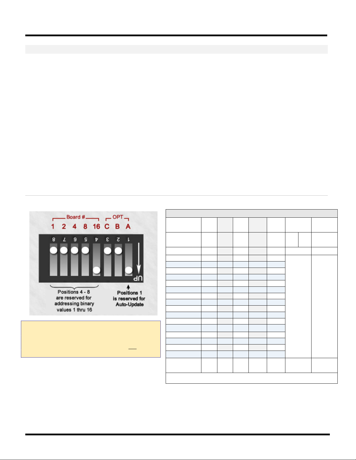
635-SERIES HARDWARE MANUAL
Binary Address Table
>
update
Position >
Board ID
OFF
ON
1
ON
2
ON 3
ON
ON 4
ON
5
ON ON
6
ON
ON 7 ON
ON
ON 8
ON 9
ON
ON
10
ON ON 11
ON
ON ON
12
ON
ON
13
ON ON
ON
14
ON
ON
ON 15
ON
ON
ON
ON
16
ON
>
update
PART 4.4.3 (REQUIRED) PRE-CONFIGURING THE BOARD ID
1. SETTING THE BOARD ID (SW2):
a) The Binary Dipswitch [SW2] is located on the center of the DSI board.
• Each board ID must be unique (no duplicates) and valid (1 thru 16).
• If you are replacing an existing board – you must use the same ID as the old board to maintain the
system programming of the readers/doors, inputs, outputs – whatever is supported.
• If you are installing a new board, the ID must be unique on the I2C Data Buss.
b) Turn “ON” only the switches needed to achieve the desired ID.
Positions 4 thru 8: for binary addressing. Find the desired value in Board ID column of table (below).
Positions 2 and 3: are unused and should remain OFF.
Position 1: should remain ON (factory default). This option enables flash auto-update.
Figure 23 – BINARY DIPSWITCH for DSI Board ID
CAUTION: DO NOT INTERRUPT BOARD POWER OR
RESET THE BOARD WHEN IT IS FLASHING.
Resetting the board or power during a flash update can
damage the factory flash. Be sure the DSI is not in the
flashing process.
Table 24: BINARY ADDRESS TABLE FOR 635-DRM
Binary Value
Dipswitch
(1) (2) (4) (8) (16) unused
8 7 6 5 4 3 2 1
Binary Value
(1) (2) (4) (8) (16) unused
Auto
< position 6 and 7 = currently unused >
< default ON – auto update flash enabled >
Auto
POSITIONS are OFF unless shown as ON
Chapter-Page 2-33

635-SERIES HARDWARE MANUAL
PART 4.2 4 (REQUIRED) INSTALLING THE 635 DSI BOARD IN THE CONTROLLER
IF You are not installing a DSI, skip this section
1. Loosen the stand-offs and mount Board (bracket) flush against the back wall of cabinet, in next available slot.
DO NOT mount bracket on end of stand-off – See diagram below
NOTE: Board installs with components facing toward power supply.
2. Tighten stand-offs on the bracket, to anchor the board firmly in position.
3. Connect the Ribbon Cable to the Data port (J4).
4. Repeat instructions (beginning at 1) for each DSI Board you will be installing.
5. DO NOT CONNECT BOARD TO THE POWER HARNESS UNTIL YOU HAVE FINISHED INSTALLING ALL BOARDS.
Figure 24 – Installing a DSI Board with bracket against back of cabinet:
This diagram shows the installation of an interface board in the next available slot.
Chapter-Page 2-34

635-SERIES HARDWARE MANUAL
RS-485
Buss
PWR
REC XMT
12v
PWR
LED
Factory
12 Vdc
GND
Board ID
D1
D- D+
SET
BRD
NUM
8 4 2 1
ON
1 2 3 4
D2
D3
D4
COM
NC
NO
COM
NC
NO
COM
NC
NO
COM
NC
NO
COM
NC
NO
COM
NC
NO
COM
NC
NO
COM
NC
NO
D5
D6
D7
D8
RY1
RY3 RY5 RY7
RY2 RY4 RY6
RY8
635-Model Rel ay Board Rev. A
Drawing approximate – not to scale.
4.5 Installing a 635-Model Output Relay Board
If you are not installing a Relay Board, skip this section.
Notice: if you are upgrading a 500-model ORM, this is the solution you will use.
NOTICE: The Relay Board can install in a single layer in the cabinet, or you can use a stacking kit which is available
from the Galaxy Product Catalog. One stacking kit allows you to stack 2 Boards onto 4 panel studs..
635-OUTPUT RELAY BOARD - FEATURES
Binary Dipswitch (SW1): is a 4-position switch for assigning the Board ID (set ID before installing).
Power Input (J1) +12V on PIN-1 from Dedicated Power Supply; use separate Power Supply (not the one powering the DSI).
PWR LED indicates board is connected to the power harness and the power is on (solid/on).
RS-485 Connection (J2) for RS-485 3-Wire (D+, D-, GND) PIN-1 = D+; PIN-2 = D-; PIN-3 = GND.
REC LED indicates board is receiving data over the RS-485 network connection (flicker/blinking = data receiving).
XMT LED indicates board is transmitting data over the RS-485 network connection (flicker/blinking = data transmitting).
RELAYS (RY-1, 2, 3, 4, 5, 6, 7, 8) there are eight Form-C SPDT Dry Relays, (Rated max. 24v, 1.5 Amps). These relays can be
wired Normally Closed (NC) or Normally Open (NO) to an output device.
OUTPUT LEDs (D1, 2, 3, 4, 5, 6, 7, 8) indicates when a relay is active/engaged (regardless of how it is wired (NO/NC)).
Figure 25 – 635 Output Board Features:
Diagram shows board’s component-side up. The boards are install flat and component-side-up, which uses 4 studs (or 2 slots).
Installer will wire the Power Input to a separate 2
Chapter-Page 2-35
Note – the 600-Model Board uses the same wiring pinout as the 635-model.
nd
power supply (i.e. not the P.S. used by the CPU/DSI ).

635-SERIES HARDWARE MANUAL
General Output (GPO/ORM)
Max Number of Relay Boards
Total Number of Relays
Per RS485 Section (port):
Up to 3 Boards
Up to 24 Relays per Section
Per DSI Board:
Up to 6 Boards
Up to 48 Relays per DSI Board
Elevator Control
Number of Relay Boards
Total Number of Relays
Per RS485 Section (port):
Up to 15 Boards
Up to 120 Relays per Section
Per DSI Board:
Up to 30 Boards
Up to 240 Relays per DSI Board
635-RELAY BOARD – INSTALLATION OF BOARD IN CONTROLLER
If you are not installing a Relay Board, then skip this section.
PART 4.5.1 PREP STEPS - BEFORE INSTALLING THE REL AY BOARDS
You must know how many boards will be on each DSI 485 Channel (Section). The use (i.e. general output or
elevator control) will determine how many boards you can support on a DSI Section. The last Output Board on the
RS485-Section must be within the 4,000 ft. max line length.
A. General Purpose Outputs:
• MAIN PANEL: must have a CPU board and a DSI board; can have Relay Boards on 2
• SECOND PANEL: second or additional panels will have only Relay Boards, wired back to DSI in main panel.
B. Elevator Control:
• MAIN PANEL: must have a CPU board, DRM Board and a DSI Board; & Relay Boards (based on cabinet size).
• SECOND PANEL: second or additional panels will have only Relay boards, wired back to DSI in main panel.
nd
power supply.
Relay Boards must be installed in a Multidrop configuration (daisy-chained) on the DSI RS485 Section (not a star).
See Appendix N for additional panel diagrams of the first and second panels.
Elevator relay boards might install only on one section of the DSI if each cab’s floors are accessed independently.
Figure 26 – Example of Relay Boards in Main Panel for General Purpose Output Relay (ORM)
Diagram shows medium Main Panel for GPO/ORM holds 2 relay boards (or 4 with stacker kits). See next diagram for 2ND Panel.
NOTICE: Relay Boards must use a separate power supply when they are in the main panel.
NOTICE: ERM Elevator control Main Panel must include a DRM board. Thus, it will hold only 1 relay board (or 2 with a stacker kit)
Chapter-Page 2-36

635-SERIES HARDWARE MANUAL
Figure 27 – Example of Relay Boards Installed in a Separate Panel
This diagram shows the Relay Boards installed in a second (auxiliary) panel. All control boards must be in the Main Panel.
The additional panels will hold . SEE PART 4.5.3 FOR CORRECT INSTALL INSTRUCTIONS.
1. You must decide how the boards will be installed in the electrical cabinets.
a. SINGLE LAYER INSTALL: Relay boards are mounted onto existing standoffs – be sure you have enough clearance
when the door is closed for the wiring to the Relays. YOU CANNOT MOUNT THE BOARD FLUSH TO THE CABINET
WALL – YOU MUST USE A SPACER (STANDOFF). SEE PART 4.5.3 FOR CORRECT INSTALL INSTRUCTIONS.
b. DOUBLE LAYER (STACKER KIT): Relay boards are mounted using the Stacker Kit that provides 12 Lock Washers
spacers (standoffs) – be sure you have enough clearance between boards and when the door is closed for the
wiring to the Relays. One kit of 12 spacers mounts 2 Relay Boards in a stacked configuration.
MOUNT THE BOARD FLUSH TO THE CABINET WALL – YOU MUST USE A SPACER (STANDOFF).
Figure 28 – Example of Single Layer vs. Stacked Install (SEE PART 4.5.3 FOR EXACT INSTRUCTIONS)
Diagram shows board’s component-side up. The boards are install flat and component-side-up, which uses 4 studs (or 2 slots).
Installer will wire the Power Input to a separate 2
nd
power supply (i.e. not the P.S. used by the CPU/DSI ).
YOU CANNOT
Chapter-Page 2-37

635-SERIES HARDWARE MANUAL
ID
Actual DIP-Switch Position
ID
Actual DIP-Switch Position
1
4
= ON 9
1, 4
= ON
2 3 = ON 10
1, 3
= ON
3
3, 4
= ON 11
1, 3, 4
= ON
4 2 = ON 12
1, 2
= ON
5
2, 4
= ON 13
1, 2, 4
= ON
6
2, 3
= ON 14
1, 2, 3,
= ON
7
2, 3, 4
= ON 15
ALL ON = 15
8 1 = ON 16
ALL OFF = 16
PART 4.5.2 CONFIGURE THE RELAY BOARD IDs (REQUIRED)
• You can do this as you install each board – but do not forget to do it.
• If you are stacking the boards, you must address the lower boards before you install the upper board.
2. You must set the Board ID before installing the boards.
(Switch positions 1 thru 4). ID 1 thru 16 are valid; each Board ID must be unique on the RS-485 bus.
RELAY BOARD # 1 BOARD # 15 BOARD # 16
Table 25: BINARY ADDRESS TABLE FOR OUTPUT RELAY BOARD
Chapter-Page 2-38

635-SERIES HARDWARE MANUAL
PART 4.5.3 INSTALLING THE BOARDS IN THE PANELS (REQUIRED)
3. INSTALLING BOARDS IN A SINGLE LAYER ONLY: << SKIP THIS STEP IF YOU ARE STACKING >>
a. Make sure you have set the Board Numbers to the appropriate, unique IDs (via binary dipswitch).
b. You may be able to use the existing standoffs (hexagonal spacers) that are in the Galaxy cabinet. You must
maintain enough space between the boards and cabinet door for the wiring going to the Relays.
c. Place board flat (component-side-up) on top of 4 spacers – NEVER MOUNT BOARD AGAINST PANEL WALL!
d. Install a lock washer on each mounting hole of the board. Install the 4 screws to anchor the board.
(go to next step to wire relays and power input)
4. INSTALLING BOARDS IN STACKED:
<< SKIP THIS STEP IF DOING A SINGLE-LAYER INSTALL >>
a. Make sure you set Board IDs to the appropriate, unique IDs before installing (via binary dipswitch).
b. Remove existing spacers from cabinet and Install the shortest hex spacers from your Stacking Kit onto the
bare studs in the cabinet. (4 hex spacers for a board) – NEVER MOUNT BOARD AGAINST PANEL WALL!
c. Place the lower Relay Board onto the spacers (you can pop ahead to next page for instructions on wiring).
d. Place 4 lock washers on mounting holes of the board and secure by installing 4 long hex spacers on each
mounting hole of the board.
At this point you may want to go ahead and wire up relays and inputs of lower board(s)
e. Place 4 more lock washers on top of each hex spacer that you installed in the prior step.
f. Install 4 swivel spacers so that the short arm of the swivel spacer is toward the upper board. The swivel
spacers allow the upper relay board to swing out of the way to allow access to the lower board. You may
want to test the swing-away clearance to ensure you have installed the swivel spacers as needed.
g. Align the upper Relay Board) onto the swivel spacers.
h. Install the last 4 washers and secure the board with the 4 screws from the stacker kit. You can complete the
wiring as needed for the relays and orange connectors.
Figure 29 – Relay Board Installation Options (Single Layer vs. Stacked)
Diagram shows board’s component-side up. The boards are install flat and component-side-up, which uses 4 studs (or 2 slots).
Installer will wire the Power Input to a separate 2
nd
power supply (i.e. not the P.S. used by the CPU/DSI ).
Chapter-Page 2-39

635-SERIES HARDWARE MANUAL
5. WIRING THE RELAYS (NO vs. NC):
a. The relays are Dry Form-C SPDT Rated at 24v 1.5 Amps.
b. You can wire the relays Normally Open (NO) or Normally Closed (NC), as needed.
Figure 30 – 635-Relay Board: Wiring the Relay Terminals
Diagram shows where to land wires for Relay Terminals.
6. WIRING THE POWER INPUT CONNECTOR:
a. You must wire the power inputs to the appropriate size power supply.
b. Remove the Orange 2-Piece Connector and wire it as follows:
• Connect the Ground wire to the side marked with the ground symbol
• Connect power to the side marked 12v
Figure 31 – 635-Relay Board: Wiring the Power Input
Diagram shows where to land wires for the Power Input.
7. DO NOT CONNECT/APPLY POWER TO THE BOARD YET.
• Also See Appendix N for additional diagrams of Output Relay panels as needed.
Chapter-Page 2-40

635-SERIES HARDWARE MANUAL
8. WIRING THE RS-485 MULTI-DROP:
Diagram shows Boards installed on the DSI Board Section-1 in a multidrop (daisy chain) configuration.
DO NOT USE A STAR CONFIGURATION ON THE 485 SECTION.
SEE NEXT PAGE FOR RS485 PINOUT GUIDE
Figure 32 – Relay Board Installation (on the 635-DSI Board’s RS-485 Multidrop)
Chapter-Page 2-41

635-SERIES HARDWARE MANUAL
DSI BOARD RS-485 (J5 / J6)
FIRST RELAY BOARD RS-485 ON MULTIDROP
A (pin 1)
to D+
B (pin 2)
to D-
GND (pin 3)
GND
Ground Drain wire at DSI END ONLY for this line segment
UNUSED (pin 4)
- -
RELAY BOARD RS-485
TO NEXT RELAY BOARD ON MULTIDROP
D+
to D+
D-
to D-
GND
GND
Ground Drain wire on shielding to one board
(do not ground both ends of the drain wire).
Drawing is not to scale.
STEP-8 PINOUT GUIDE FOR RS-485 MULTIDROP
• Relay Boards must be installed in a multidrop (daisy chain) configuration.
DO NOT USE A “STAR” CONFIGURATION ON THE RS485 SECTION.
•
Table 26: WIRING PINOUT FROM 635-DSI TO FIRST RELAY BOARD
Use this pinout guide for the first Relay board on the multidrop.
Never wire more than one board to a DSI Section.
WIRING PINOUT RELAY BOARD
Table 27: WIRING PINOUT FROM ONE RELAY BOARD TO NEXT RELAY BOARD
Use this pinout guide for each Relay board on the multidrop.
Only one (1) Relay Board can be wired to a Relay Board.
Never wire more than one board to another board.
Chapter-Page 2-42
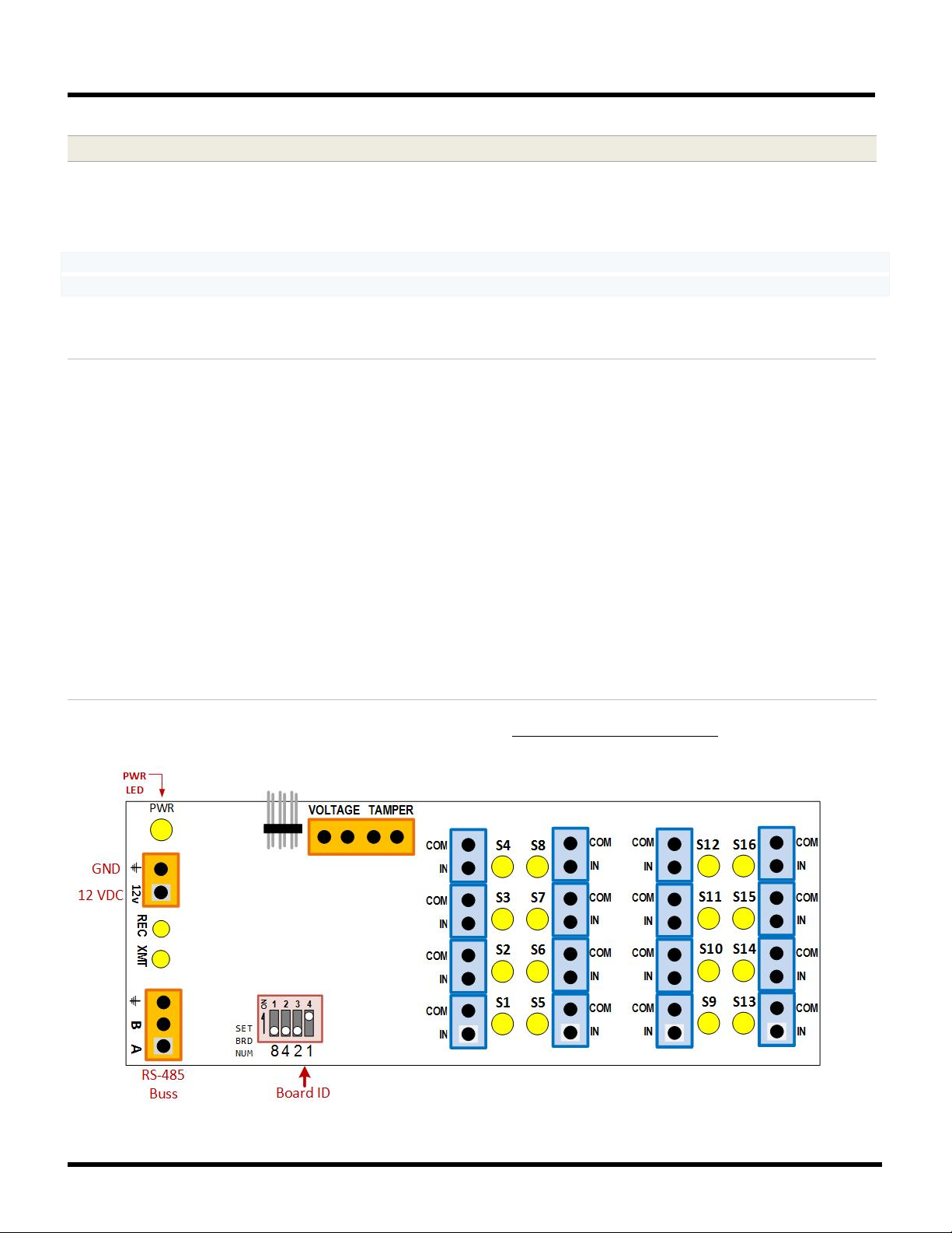
635-SERIES HARDWARE MANUAL
4.6 Installing 635-Model Input Module
If you are not installing a 635 Input Board, skip this section.
NOTICE: If you are upgrading older 500-series Controllers with 500 AMMs, this is the solution you will use.
NOTICE: The Input Boards can be installed in a single layer (1 Input Board on 4 studs), or you can use a stacking kit available from the Galaxy Product Catalog. One stacking kit allows you to stack 2 Boards onto 4 panel studs.
635-INPUT MODULE - FEATURES
Binary Dipswitch (SW1): is a 4-position switch for assigning the Board ID (set ID before installing).
Power Input (J1) +12V on PIN-1 from Dedicated Power Supply; use separate Power Supply (not the one powering the DSI).
PWR LED indicates board is connected to the power harness and the power is on (solid/on).
RS-485 Connection (J2) for RS-485 3-Wire (A, B, GND) PIN-1 = A; PIN-2 = B; PIN-3 = GND.
REC LED indicates board is receiving data over the RS-485 network connection (flicker/blinking = data receiving).
XMT LED indicates board is transmitting data over the RS-485 network connection (flicker/blinking = data transmitting).
INPUT LEDs (S1 thru S16) indicate when an input is active.
PLUGGABLE, 2-WAY PCB INPUT CONNECTORS: Sixteen (16) connectors support 16 inputs per board. (J5, J6, J7, J8)
There are Four (4) banks of pluggable, 2-Pin Connectors used for wiring the inputs. Each bank
mounted in a row so that it looks a single 8-pin connector, but each 2-pin connector can be unplugged from the board for easy
of wiring. The connectors are 2-way connectors, which offer retention screw contacts for landing stranded wires, or push-in
contacts for single conductor wires.
Figure 33 – 635-Input Module Features
Diagram shows board’s component-side up. The boards are install flat and component-side-up, which uses 4 studs (or 2 slots).
Installer will wire the Power Input to a separate 2
nd
power supply (i.e. not the P.S. used by the CPU/DSI ).
(J5/J6/J7/J8) of 2-pin connectors is
Chapter-Page 2-43

635-SERIES HARDWARE MANUAL
General Input (AMM)
Number of Relay Boards
Total Number of Relays
Per RS485 Section (port):
Up to 16 Boards
Up to 256 Inputs per Section
Per DSI Board:
Up to 32 Boards
Up to 512 Inputs per DSI Board
635-INPUT MODULE – INSTALLATION OF BOARDS IN CONTROLLER PANELS
If you are not installing an Input Board, then skip this section.
PART 4.6.1 PREP STEPS - BEFORE INSTALLING THE INPUT BOARDS
1. You must know how many boards will be on each DSI 485 Channel (Section).
The last Input Board on the RS485-Section must be within the 4,000 ft. max line length.
A. INPUT BOARD:
• MAIN PANEL: must have a CPU board and a DSI board; and Relay Boards on separate power supply.
• SECOND PANEL: second or additional panels may have only the Relay Boards.
NOTICE: Each Input Board counts as 1 DEVICE toward the CPU’s 64-Device maximum – regardless of how many
inputs are connected to the board. This makes a max of 64 Input Boards per CPU.
However, you may have those 64 boards scattered across multiple DSI boards depending on the topology of your
building. The more DSI boards you put in the main panel, the less room for input boards.
Input Boards must be installed in a Multidrop configuration (daisy-chained) on the DSI RS485 Section.
Figure 34 – Basic Example of Input Boards Installed in the Main Panel
Diagram shows medium Main Panel for Inputs will hold 2 boards (or 4 with stacker kits). See next diagram for 2ND Panel.
NOTICE: Input Boards can use a separate power supply when they are in the main panel.
Chapter-Page 2-44

635-SERIES HARDWARE MANUAL
Figure 35 – Basic Example of Input Boards Installed in a Separate Panel
This diagram shows the Input Boards installed in the second (auxiliary) panel. The CPU, DSI are in the Main Panel.
2. You must decide how the boards will be installed in the electrical cabinets.
a. SINGLE LAYER INSTALL: Relay boards are mounted onto existing standoffs – be sure you have enough clearance
when the door is closed for the wiring to the Relays. YOU CANNOT MOUNT THE BOARD FLUSH TO THE CABINET
WALL – YOU MUST USE A SPACER (STANDOFF). (SEE PART 4.6.3 FOR EXACT INSTRUCTIONS)
b. DOUBLE LAYER (STACKER KIT): Relay boards are mounted using the Stacker Kit that provides 12 Lock Washers
spacers (standoffs) – be sure you have enough clearance between boards and when the door is closed for the
wiring to the Relays. One kit of 12 spacers mounts 2 Relay Boards in a stacked configuration.
MOUNT THE BOARD FLUSH TO THE CABINET WALL – YOU MUST USE A SPACER (STANDOFF).
Figure 36 – Example of Single Layer vs. Stacked Install (SEE PART 4.6.3 FOR EXACT INSTRUCTIONS)
Diagram shows board’s component-side up. The boards are install flat and component-side-up, which uses 4 studs (or 2 slots).
nd
Installer will wire the Power Input to a separate 2
power supply (i.e. not the P.S. used by the CPU/DSI ).
YOU CANNOT
Chapter-Page 2-45

635-SERIES HARDWARE MANUAL
ID
Actual DIP-Switch Position
ID
Actual DIP-Switch Position
1
4
= ON
9
1, 4
= ON
2 3 = ON
10
1, 3
= ON
3
3, 4
= ON
11
1, 3, 4
= ON
4 2 = ON
12
1, 2
= ON
5
2, 4
= ON
13
1, 2, 4
= ON
6
2, 3
= ON
14
1, 2, 3,
= ON
7
2, 3, 4
= ON
15
ALL ON = 15
8 1 = ON
16
ALL OFF = 16
PART 4.6.2 CONFIGURE THE BOARD IDs (REQUIRED)
• You can do this as you install each board – but do not forget to do it.
• If you are stacking the boards, you must address the lower boards before you install the upper board.
3. You must set the Board ID before installing the boards.
(Switch positions 1 thru 4). ID 1 thru 16 are valid; each Board ID must be unique on the RS-485 bus.
INPUT BOARD # 1 BOARD # 15 BOARD # 16
Table 28: BINARY DIPSWITCH SETTINGS FOR INPUT BOARD
Chapter-Page 2-46
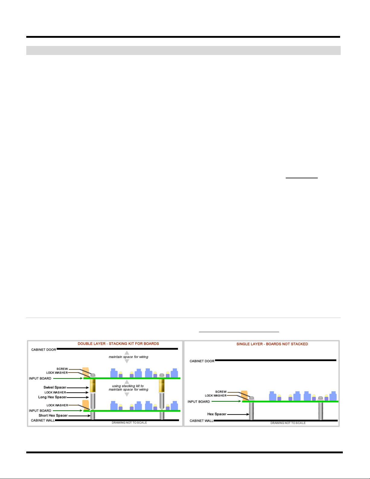
635-SERIES HARDWARE MANUAL
PART 4.6.3 INSTALLING THE BOARDS IN THE PANELS (REQUIRED)
4. INSTALLING BOARDS IN A SINGLE LAYER ONLY: << SKIP THIS STEP IF YOU ARE STACKING >>
a. Make sure you have set the Board Numbers to the appropriate IDs.
b. You may be able to use the existing standoffs in the Galaxy cabinet if you can maintain enough space for
the wiring to the input connectors.
c. Place a lock washer on each of the 4 mounting holes of board.
d. Install 4 screws to anchor the board(s) onto the standoffs (spacers).
e. GO TO THE STEP ON WIRING THE INPUTS AND OTHER CONNECTORS.
5. INSTALLING BOARDS IN STACKED:
<< SKIP THIS STEP IF DOING A SINGLE-LAYER INSTALL >>
a. Make sure you set Board IDs to the appropriate, unique IDs before installing (via binary dipswitch).
a. Remove existing spacers from cabinet and Install the shortest hex spacers from your Stacking Kit onto the
bare studs in the cabinet. (4 hex spacers for a board) – NEVER MOUNT BOARD AGAINST PANEL WALL!
b. Place the lower Input Board onto the spacers.
c. Place 4 lock washers on the boards 4 mounting holes and install 4 long hex spacers to anchor the board.
• At this point you may want to go ahead and wire up relays and inputs of lower board(s)
d. Place 4 more lock washers on top of each hex spacer that you installed in the prior step
e. Install the 4 swivel spacers so that the short arm of the swivel spacer is toward the upper board. The swivel
spacers allow the upper relay board to swing out of the way to allow access to the lower board. You may
want to test the swing-away clearance to ensure you have installed the swivel spacers as needed.
f. Align the upper Relay Board onto the swivel spacers.
g. Install the last 4 washers and secure the board with the 4 screws from the stacker kit. You can complete the
wiring as needed for the relays and orange connectors.
Figure 37 – Input Board Installation Options (Single Layer vs. Stacked)
Diagram shows board’s component-side up. The boards are install flat and component-side-up, which uses 4 studs (or 2 slots).
Installer will wire the Power Input to a separate 2
nd
power supply (i.e. not the P.S. used by the CPU/DSI ).
Chapter-Page 2-47

635-SERIES HARDWARE MANUAL
6. WIRING THE INPUTS:
Wire the inputs to the pluggable/ interlocking, 2-way 2-pin TB Connectors.
The pluggable/interlocking 2-pin connectors are arranged into four banks of connectors. You can unplug each one
from the board for ease of wiring (but be careful to observe the polarity of your wiring.
NOTICE: These are 2-way TBC connectors, which means ….
• If you are using stranded wire, anchor stranded wiring using the screw contacts that come in from the side.
• If you are using single-conductor wire, use “push-in” contacts that allow you to push the solid wire in from
the top-side of the connector.
Figure 38 – Input Board Component Designations and Connector Pinouts
Diagram shows board’s component-side up - with Component designations & Connector pinout markings.
7. WIRING THE “TAMPER” & “VOLTAGE ALARM” INPUTS (4-PIN Connector):
Figure 39 – Input Board: Voltage-monitoring and Tamper-switch Wiring
Wiring diagram for tamper switch and voltage monitoring.
Chapter-Page 2-48

635-SERIES HARDWARE MANUAL
8. WIRING THE POWER INPUT CONNECTOR:
Remove the Orange 2-Piece Connector and wire it as follows:
• Connect the Ground wire to the side marked with the ground symbol
• Connect power to the side marked 12v
Figure 40 – Input Board: Power Input Wiring
Wiring diagram for board power input connector.
Ground
+12 VDC
9. DO NOT CONNECT/APPLY POWER TO THE BOARD YET.
Also See Appendix N for additional diagrams of Output Relay panels as needed.
Chapter-Page 2-49

635-SERIES HARDWARE MANUAL
10. WIRING THE RS-485 MULTI-DROP:
Diagram shows Boards installed on 635-DSI Board Section-1 in a multidrop (daisy chain) configuration.
DO NOT USE A STAR CONFIGURATION ON THE 485 SECTION.
SEE NEXT PAGE FOR RS485 PINOUT GUIDE
Figure 41 – Input Board Installation (wiring 635 Input Boards to the 635-DSI RS485-Multidrop)
Chapter-Page 2-50

635-SERIES HARDWARE MANUAL
DSI BOARD RS-485 (J5 / J6)
FIRST INPUT BOARD RS-485 ON MULTIDROP
A (pin 1)
to A
B (pin 2)
to B
GND (pin 3)
GND
GND (pin 3)
Ground Drain wire at DSI END ONLY for this line segment
UNUSED (pin 4)
- -
INPUT BOARD RS-485
TO NEXT INPUT BOARD ON MULTIDROP
A
to A
B
to B
GND
GND
Ground Drain wire to only one board
(do not ground both ends of the drain wire).
STEP-10 PINOUT GUIDE FOR RS-485 MULTIDROP
• Boards must be installed in a multidrop (daisy chain) configuration.
DO NOT USE A “STAR” CONFIGURATION ON THE RS-485 SECTION.
•
Table 29: WIRING PINOUT FROM THE 635-DSI TO FIRST INPUT BOARD
Use this pinout guide for the first Input board on the multidrop.
Never wire more than one board to a DSI Section.
Table 30: WIRING PINOUT FROM ONE INPUT BOARD TO NEXT INPUT BOARD
Use this pinout guide for each individual Input board on the multidrop.
Only one (1) Input Board can be wired to a Input Board.
Never wire more than one board to another board.
Chapter-Page 2-51

635-SERIES HARDWARE MANUAL
IMPORTANT: Do not run low-voltage wiring in the same bundle or conduit with high-voltage
communication interference and results in equipment or system failure.
CAUTION: Risk of Electric Shock, Electrical Arcs, Fire or Burns if battery is not properly wired.
Reversing polarity can cause electrical shock and result in serious bodily injury.
STEP 5. Applying Power to the Controller
5.1 Pull all field wiring into the controller
1. Pull all the field wiring into the controller cabinet, using conduit and the supplied knock-outs taking care to
not pinch or strain wiring.
2. Leave enough extra wire to make a service loop.
3. Also, pull the LAN cable into the cabinet for the CPU connection.
!
wires. Running data (Reader Data and LAN) wires near high frequency wires can cause severe
5.2 Connecting Back-up Battery and Power Transformer to the Power Supply
CAUTION: OBSERVE POLARITY WHEN CONNECTING THE BATTERY.
1. Attach the backup battery (12 V / 8 A-hr or equivalent) to the power supply at the terminals marked
“ + BAT – ”. The battery sits inside the cabinet in front of the power supply.
2. Wire the power transformer to the controller power supply (min. 18 gauge) at the terminals
marked “AC”
Example: Altronix 12 VDC Power Supply. Observe Terminal Markings & polarity of the Power Supply you purchased.
3. Plug the power transformer into the 115 AC 50 Hz wall outlet (power source).
4. Check DC volts output of the power supply inside the controller (should see 13.8 VDC).
5. CONNECT THE CPU POWER CONNECTOR TO THE CPU BOARD – POWER LED = SOLID/ON.
Chapter-Page 2-52

635-SERIES HARDWARE MANUAL
IMPORTANT: When installing a two power supplies for DRMs inside the controller, you should
factory) but if you are doing it yourself, you must common the grounds during installation).
!
!
5.3 About adding an Auxiliary Power Supply inside the Controller
The controller has room and mounting studs for a second power supply, if needed to support proximity
readers, Relay Boards, Input Boards, etc.
For the standard 8-door controller, if there are more than four (4) proximity readers attached to the
controller, you may need two SMP3 Power Supplies. The first 4 prox readers (on first 2 DRMs) can be
supported on the first Power Supply. The second 2 DRMs will support the next 4 prox readers and should
be wired to the second SMP3 power supply.
!
5.4 About External Power Supplies outside the Controller
Peripheral hardware must be powered from an external power supply that is separate from the controller.
5.5 Installing Suppression Diodes at the Door Locks
Surge suppression diodes should be installed in reverse bias and parallel to the lock to absorb kickback.
Install diodes as far away from the controller as possible.
common the grounds between the power supplies. (This may already be done if ordered from
IMPORTANT: ALL LOCKS MUST BE POWERED FROM A SEPARATE POWER SUPPLY AT THE LOCK
(OUTSIDE OF THE CONTROLLER). DO NOT COMMON THE LOCK POWER TO THE CONTROLLER POWER.
IMPORTANT: Biometric, Wireless, CAC, and IP readers require separate external power supply that is not
mounted inside the Galaxy controller . DO NOT COMMON THE EXTERNAL POWER TO THE CONTROLLER POWER.
Figure 42 – Installing a Surge Suppression Diode for Door Lock
Chapter-Page 2-53

635-SERIES HARDWARE MANUAL
STEP 6. Program the 635 CPU Board
Configuring the CPU Board can be done from a Web Browser via the Embedded Web Page. Using the
Configuration Tool will allow you to find the controllers by their MAC address as long as the door is open
(tamper switch open) and they are on the same network segment as your PC/Laptop. You can still connect
to the serial programming port of the CPU using a standard RS232 serial cable using Putty or similar tool
HyperTerminal® ( a serial programming cable that is supplied with the controller).
If you need to make a serial cable, the instructions are found in Chapter 1 CPU Programming Requirements.
6.1 Connecting to the CPU Board via Putty® or HyperTerminal®
1. Connect the serial programming cable to PC com port and the J4 serial port on 635 CPU.
2. Start a HyperTerminal Session on the PC using the following parameters:
Bits per Second = 57,600K
Data Bits = 8
Parity = None
Stop Bits = 1
Flow Control = None
The HyperTerminal session will display a blank screen at this point.
3. Apply power to the CPU board by plugging in the orange power connector from the wiring
harness to J6 / J7.
4. Type “install” at the login prompt to begin programming session. Typing “config” then
press ENTER, then type “0” and press ENTER, will allow the user to program the CPU. The
“boards” command displays a list of boards that are currently online on the I2C buss. The
“help” command will display a list of valid commands.
When prompted, you must type “yes” lower case to save the configuration – you can
cycle back around by reissuing the CONFIG command if you miss-keyed or skipped a field. If you do
not save your programming, the board will lose the settings the next time it is power failed.
login: install
635 Control Module
System was WARM started
>>>
Chapter-Page 2-54

635-SERIES HARDWARE MANUAL
6.1 Programming the 635-Model CPU Board via Web Page
This subsection provides quick steps for programming the CPU from the embedded web page. The CPU comes from
the factory with a default 192 … IP Address. You can identify each CPU by its serial number.
SEE CHAPTER-1 FOR A FULL LIST OF IT REQUIREMENTS
• Specific port numbers must be available and not blocked by firewalls, switches, or routers. System
Galaxy uses port numbers 1433, 5010, 3001, 4000, 4001, 4002, and 4003
• Windows OS need to set PC firewall at the Communication Server to accept the File and Print Sharing,
sqlservr.exe and sqlbrowser.exe.
• 635 Controller: TCP/IP over LAN/WAN 10/100 Mb Ethernet/Full Duplex at port side.
• Unique, IP Addresses must be given to each Galaxy Panel (CPU) and the computers that host the GCS
Communication and Event Services.
If private IP Addresses are not available, a non-routable IP Address should be used.
NOTICE: If DHCP addressing is used, and the DHCP server goes offline or changes the addresses, then
connectivity between the server and loops will be adversely affected!
.
1. Install the 635 Web Configuration Tool on a PC that is connected to the same broadcast domain as the 635
panel/s you wish to program or test.
2. Click desktop icon to start the Web Tool (your default browser opens).
3. If dual NIC cards are used, select the correct NIC card in the droplist.
Figure 43 – Example of 635 Web Config Tool Screen
Chapter-Page 2-55
 Loading...