

Page 1
V H F
USER'S MANUAL
®
Page 2

Page 3

System Components....................................................................................1
Functions of the VESR Receiver...................................................................2
Functions of the VSCR Receiver....................................................................3
Functions of the HH18 Hand Held Transmitter................................................4
Functions of the MBP18 Body Pack Transmitter.............................................5
Troubleshooting............................................................................................6
Specifications...............................................................................................7
Contents
Contents
Page 4
1
System Components
System Components
System Components
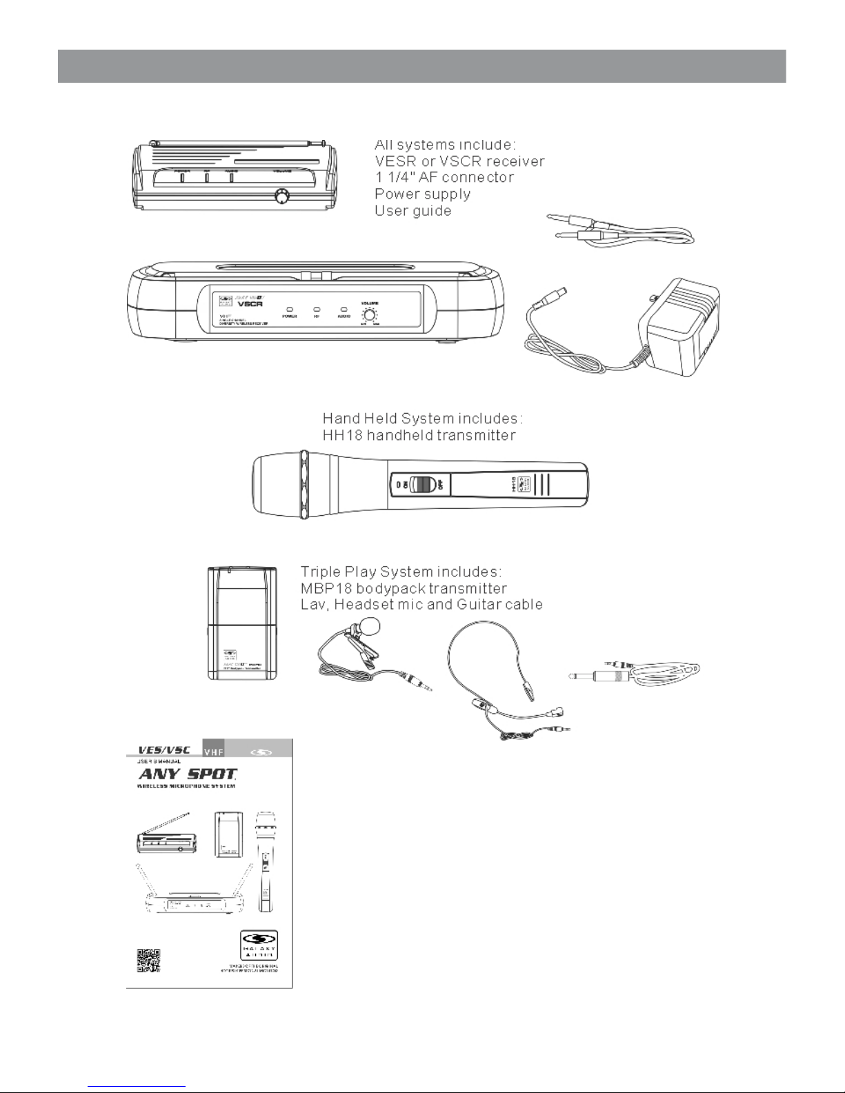
All systems include:
VESR or VSCR receiver
1 1/4" AF connector
Power supply
User guide
Hand Held System includes:
HH18 handheld transmitter
Triple Play System includes:
MBP18 bodypack transmitter
Lav, Headset mic and Guitar ca ble
VE SR
VS CR
HH 18
MB P18
LV13-U BK
HS 13-U BK
Gu ita r Ca ble
Manual
Page 5

2
Functions of the VESR Receiver
Functions of the VESR Receiver
Front Panel
Rear Panel
1/4" Unbalanced Audio Output 12-18Vdc in Power adaptor
Power Indicator: Lights when
is receiving power
RF signal indicator:
lights when transmitter is
turned on indicating reception
of RF signal
Audio Signal Indicator:
Lights when receives audio
from transmitter
Audio output level control
Clockwise increases
the audio output, Counter
Clockwise decreases the
audio output.
Page 6

Functions of the VSCR Receiver
Functions of the VSCR Receiver
Rear Panel
Front Panel
12-18Vdc in 12-18Vdc in
Power adaptor
1/4" Unbalanced Output
Mute threshold adjustment
The factory default usually needs
no adjustment. However if there is
any interference, this threshold
value can be increased by turning
the knob clockwise until RF signal
lamp goes out.
3
Power Indicator: Lights when
is receiving power
RF signal indicator:
lights when transmitter is
turned on indicating reception
of RF signal
Audio Signal Indicator:
Lights when receives audio
from transmitter
Audio output level control
Clockwise increases
the audio output, Counter
Clockwise decreases the
audio output.
Page 7

Functions of the HH18 Hand Held Transmitter
Functions of the HH18 Hand Held Transmitter
Changing Batteries:
Expected life for two 1.5V AA alkaline batteries is about 8 hours.
When the battery indicator lights the batteries should
be changed immediately (as shown below).
Microphone Grille
Low Battery Indicator
Lights when the battery is low
Power Switch
Battery Door
4
Page 8

Functions of the MBP18 Body Pack Transmitter
Functions of the MBP18 Body Pack Transmitter
Wearing the Body Pack Transmitter:
Clip the transmitter to belt , or slide a guitar
strap through the transmitter clip , as shown.
For best results, slide the transmitter until the
belt is pressed against the base of the clip.
Changing Batteries:
Expected life for two 1.5V AA alkaline batteries is
about 8 hours. When the battery indicator lights
RED the batteries should be changed
immediately as shown to the left.
On/Off/Mute switch.
Gain adjustment switch
Three gain settings are available on
MBP18,
Mic: Microphone
0dB: Guitar with passive pickups
-10dB: Guitar with active pickups
Microphone Input Jack
Power/Low indicator light
Red glow indicates low batteries and
the batteries should be changed.
5
Page 9

Trouble Shooting
Trouble Shooting
Trips for Improving System Performance
• Maintain a line of sight between transmitter and antenna.
• Avoid placing the receiver near metal surfaces or any digital
equipment (CD players, computes, etc)
• Keep the receiver away from the wall and over 3 feet from the ground
• Cellular telephones and two-way radio and such can interfere with the
transmission, maintain a distance from interfering equipment or any
cause of Interference.
Troubles Shooting
No sound or faint
sound
ISSUE INDICATOR STATUS SOLUTION
Power indicator off
Transmitter ON Indicator
stop flashing
Turn on transmittar
Make sure the +/- indicator on battery
match the transmitter terminals
Make sure AC adapter is securely
plugged Into electrical outlet and into
DC Input connector on rear panel of
receiver.
Receiver RF indicator
glows
Turn the receiver up
Turn up the Gain adjustment switch in
the transmittar
Check the power connection of the
receiver and amplifier or mixer
Receiver RF indicator off,
transmitter indicator ON
Take the receiver away from any metal
objects.
Check whether there is obstruction
between receiver and transmitter
Move the transmitter near the
receiver.
Check the receiver and transmitter
frequency
Transmitter low battery
Indicator ON
Change the batteries in transmitter
Distortion or
unwanted noise
burst
Receiver RF indicator ON Try removing nearby sources of RF
interference (CD players, computers,
digital effects. In-ear moni tor s ystems,
etc.)
Distortion level
increases gradually
Transmitter low battery
Indicator ON
Change the batteries in transmitter
Adjust transmitter again and receiver
volume as necessary
Sound level different
from cabled guitar or
microphone, or
when using different
guitars
6
Page 10

Specifications
Specifications
VES/VSC System
Frequencies:
CODE V54 173.8 MHz
CODE V59 174.1MHz
CODE V60 174.5MHz
CODE V61 174.8MHz
Operating Range under Typical Condition: 150' (50m)
Note: actual range depends on RF signals
absorption, reflection, and interference.
Audio Frequency Response: (+/-3 dB) 60Hz~16KHz
Total Harmonic Distortion: (+/- 30 KHz deviation,
1 KHz tone) <1%
Dynamic Range: >90 dB (A - weighted)
Operating Temperature Range: 14º F to 122ºF
(-10 ºC to +50ºC)
Note: battery characteristics may limit the range
VESR Receiver:
Audio Output Level Maximum: (ref. +/-30 KHz. 1 KHz)
1/4" connector (into 3000 ohm load): -18 dBV
Output Impedance: 1/4" connector 1kilohm
Sensitivity: (intermediate frequency adjustment
audio noise output: <-92 dB)
Image Rejection: > 40dB
Dimensions: 1.4" x 6" x 4"
(35mm H X 150mmW X 100mm D)
Weight: 6.17oz (175g)
Power Requirements: 12-18 Vdc at 400 mA , supplied
by external power supply
VSCR Receiver:
Audio Output Level Maximum: (ref. +/-30 KHz. 1 KHz)
1/4" connector (into 3000 ohm load): -18 dBV
Output Impedance: 1/4" connector 1kilohm
Sensitivity: (intermediate frequency adjustment
audio noise output: <-92 dB)
Image Rejection: > 40dB
Dimensions: 1.73" x 9.25" x 4.6"
(44mm H X 235mmW X 118mm D)
Weight: 11.3 4o z (3 21 .4 8 g)
Power Requirements: 12-18 Vdc at 400 mA , supplied
by external power supply
Body pack Transmitter MBP18:
Audio Input Level Maximum: 0dBV ~ +20 dBV
Gain adjustment Range: 30dB
Input Impedance: 470 kilohm
Dimensions: 4.12" x 2.6" x 0.91"
(105mm H x 65mm W x 23mm D)
Weight: 2.9oz (82.21g) without batteries
Power Requirement: 2 - AA alkaline batteries
or rechargeable
batteries. Battery life
about 8 hours (Alkaline)
Handheld Transmitter HH18:
Audio Input Level maximum: 0dBV
Dimensions: (including the microphone)
2" x 9.6"
(245mm x 53mm Diameter)
Weight: 7.42oz (210.35 g)
Power Requirement: 2 - AA alkaline batteries
or rechargeable
batteries. Battery life
about 8 hours (Alkaline)
7
Page 11

Page 12

1-800-369-7768 www.galaxyaudio.com
Specifications in this manual are subject to change without notice.
V04242013
Printed in China
© Copyright Galaxy Audio 2012
WARRANTY Information can be viewed online at
http://www.galaxyaudio.com/warranty.php
THREE YEAR LIMITED W ARRA NTY
USER'S MANUAL
 Loading...