

Page 1

Page 2

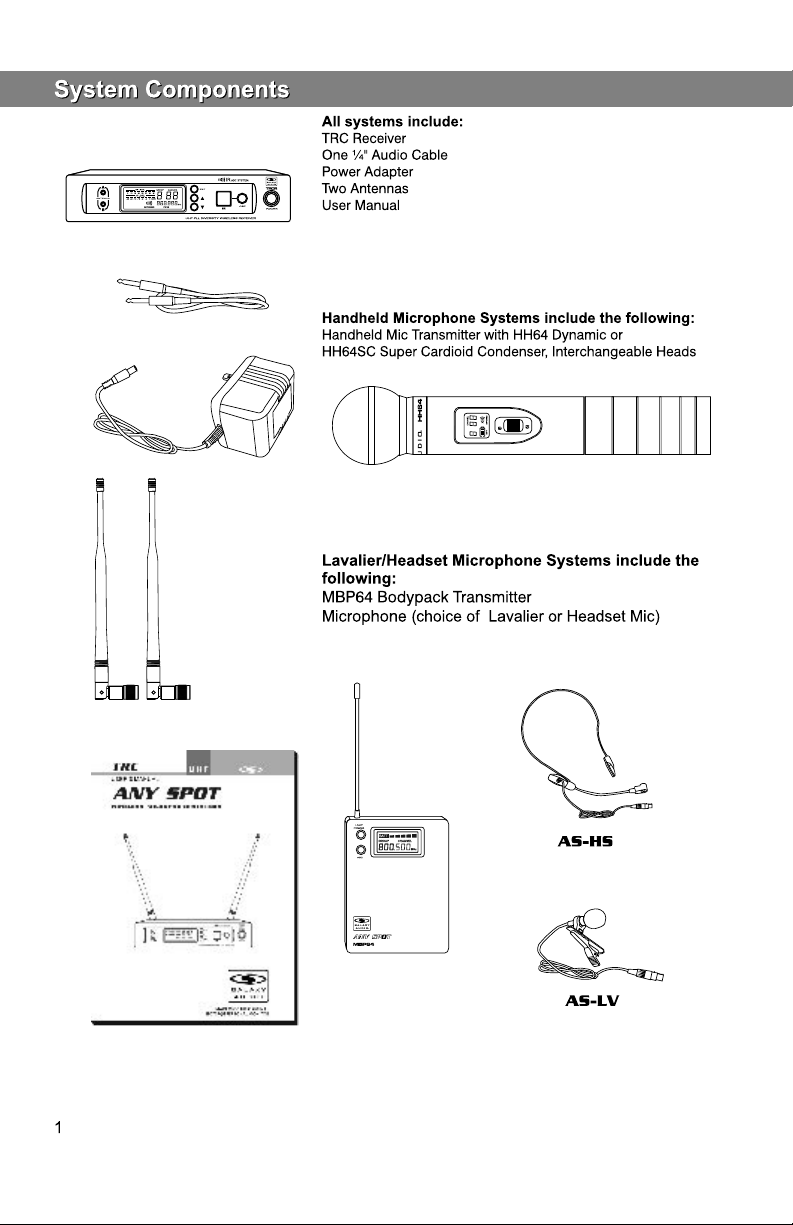
System Components.........................................1
TRC Receiver Features.....................................2
HH64 Handheld Transmitter...............................3
MBP64 Body Pack Transmitter...........................4
System Setup....................................................5
Rack-Mounting the Receivers............................6
Tips for Improving System Performance.............7
Troubleshooting.................................................7
Specifications....................................................8
Page 3

Congratulations! Welcome to the AS-TRC wireless mic system. To users who need to build an advanced
UHF wireless system, the AS-TRC provides an excellent solution. With 120 frequency choices, the AS-TRC is
Ideal for various wireless applications such as live shows, broadcast, meetings, instrument
pickups, etc. Touch buttons and liquid crystal displays provide a fast and simple system setup.
This User Guide will provide all the details you need to operate the system efficiently.
Page 4
Page 5

1
Antenna A LED.
When lit, Antenna A is active.
2
Antenna B LED.
When lit, Channel B antenna is active.
3
LCD Panel.
Please See“system setup”on page 7.
4
System setting button.
Please See“system setup”on page 7.
5
DOWN button of the System Menu.
Please See“system setup”on page 7.
6
UP button of the System Menu.
Please See“system setup”on page 7.
7
IR window.
This window sends an infrared signal to the transmitter
for frequency synchronization.
8
Synchronizing signal transmit button
Press this button to establish infrared connection
between the receiver and transmitter.
9
Power switch
Press and Hold for Power On/Off.
1
Power Adapter Connection. Use only supplied adapter or
equivalent.
2
Fine adjustment of mute threshold level.
Use this to set the threshold of the mute, which is factory
set and usually does not need to be adjusted. If there are
any interference signals, this threshold value can be increased
by turning the knob clockwise until RF signal lamp goes out.
3
¼" Audio Output Jack.
4
XLR Audio Output.
5
Antenna Jack B 50 ohm.
6
Antenna Jack A 50 ohm.
Page 6

1
Condensor mic
2
Dynamic mic
3
LCD screen
Please See “system setup ” on page 7.
4
Power Switch
5
Microphone Input Sensitivity Control.
Left turn for output level decrease, right
turn for output level increase.
6
IR port Receivers infrared beam to synchronize frequencies.
Changing Batteries:
Batteries should be replaced when LCD indicator flashes.
Unscrew the battery cover as shown below. Install
two AA alkaline batteries, while observing correct polarity
indicators in the battery tray.
Expected life for two AA alkaline batteries is 8 hours.
Page 7

1
Antenna.
2
Gain Switch.
There are three Gain settings on the MBP64. Select the
setting most suitable to your application.
Mic: Microphone Level
0: Guitar Level
-10dB: Line Level
3
Low Voltage/IR Transmission LED.
LED On: Battery Voltage OK.
LED Off: the Battery Voltage is Low.
Flashing LED: IR transmission is in progress
4
3-pin Input Jack.
5
Power/Backlight Control button
Press and Hold for Power On/Off.
Press and Release for Back-light On/Off.
6
ASC Frequency Synchronization Button.
Press this button to automatically set the Transmitter frequency
to match that of the Receiver. Use in conjunction with Receiver’s
ASC control.
7
LCD screen
See “system setup” on page 7.
8
IR Window Point this window towards IR window on Receiver during
ASC frequency synchronization.
How to Wear the Bodypack Transmitter:
Slide the transmitter clip onto the belt or run a guitar strap
through the transmitter clip , as shown in the diagram at left.
2
1
Battery Replacement :
The life expectancy of two alkaline batteries is about six hours.
When the BATT indication symbol on the display screen is
flashing as shown in the diagram below, the batteries should be
replaced immediately, as shown in the diagram on the left.
Page 8

TRC Receiver Setup:
Frequency Group No. and Channel No. selection:
Press“SET”key, and “GROUP” will flash. Press or key to select
suitable frequency group number, as shown in Diagram on the left. Then
press“SET”key, and “CHANNEL”flashes. Press or key to
select suitable channel, as shown in Diagram on the left.
1
2
Note: when using several systems, you may set all the systems
to the same group number, and then set a unique channel for each system
in this group.
Receiver Volume Control:
This device features an electronic volume control system. Under the normal
screen, press or key to control the output volume of the receiver
(there are 64 volume levels) as shown in Diagram on the left.
Normal Display:
RF level, Audio Level, Group Number, Channel, and Frequency, as
shown in Diagram on the left.
Automatic Transmitter Frequency Setting (ASC):
HH64 Handheld Transmitter:
4
3
Point its IR window towards the IR window on the Receiver. Press the
“ASC” key on the Receiver. Verify the frequencies match.
MBP64 Bodypack Transmitter:
Point the IR window of the Bodypack Transmitter towards the IR window of the
Receiver. Press “ASC” key on the Receiver and then the “ASC” key of
the Bodypack Transmitter.
Verify the frequencies match.
Whenever the “ASC” key of the receiver is pressed, synchronizing signal
will be transmitted continuously for 25 sec, and “INFRARED” symbol on
the screen also flashes, as shown in Diagram on the left.
5
When the infrared receiving circuit is enabled, “INFRARED” symbol on
the Handheld Transmitter will flash and the entire display screen of the
Bodypack Transmitter will flash (the infrared transmission indicator lamp will
also flash at the same time).
Notes: when establishing infrared connection between the receiver and the
transmitter, the distance between them should not exceed 0.5m. When more
than one system are used, only IR window of one transmitter should be pointed
to the receiver for each infrared connection.
Transmitter Status Indications:
Battery voltage indication:
There are five battery voltage level indicators for the Handheld Transmitter,
and there are six battery voltage level indicators for waist worn transmitter,
as shown in Diagram on the left.
Group Number and Channel Number Indication:
After the infrared connection between the receiver and the transmitter is
completed, the same group number and channel as those of the receiver
will be indicated on the Handheld transmitter, and the display screen of
the Bodypack Transmitter will give a 5-sec steady indication of the Group
and Channel Numbers, as shown in Diagram on the left. Then it returns
to normal status indications.
Normal Indications on the Display:
Battery voltage, group number and channel are displayed on the Handheld
Transmitter, and battery voltage and frequency are displayed on the
Bodypack Transmitter, as shown in Diagram on the left.
1
2
3
Page 9

Two TNC connecting cables (optional)
Two TNC connectors (optional)
Optional Rack Shelf
for mounting two Receivers
side by side.
MRTD/P/T
Included Single Rack Ears
Page 10

Tips for improving System Performance
Maintain a line of sight between transmitter and antenna.
■
Avoid placing the receiver near metal surfaces or any digital equipment (CD players, computers, etc)
■
Keep the receiver away from the wall and at least 1m from the ground.
■
Cellular telephones and two-way radios can interfere with the operation of wireless systems.
■
Do not use these devices in close proximity to the wireless systems.
Troubleshooting
Issue Indicator Status Solution
No sound or faint
sound.
Distortion or
unwanted noise.
Distortion level
increases gradually.
Transmitter LCD off.
Receiver LCD off.
Receiver indicates RF.
Receiver indicates No RF.
Transmitter LCD on.
The battery power indicator
light on LCD flashes.
Receiver indicates RF.
Transmitter power indicator
light flashing on the LCD.
Turn on transmitter
Make sure the batteries are installed
correctly.
Make sure AC adapter is securely
plugged into electrical outlet and into DC
input connector on rear panel of receiver.
Increase receiver volume.
Make sure Gain adjustment switch on
the transmitter is set correctly (applies
only to MBP76 Bodypack.)
Make sure Transmitter and Receiver
are set to the same frequency.
Make sure Transmitter is in range of
Receiver.
Make sure no large metal objects are
near Transmitter or Receiver.
Change the batteries in transmitter.
Remove nearby sources of RF interference (CD players, computers,
in-ear monitor systems, etc.)
Replace transmitter batteries.
Sound level different
from cabled guitar or
microphone, or when
using different guitars.
Adjust transmitter Gain and Receiver
Volume as necessary.
Page 11

System
Frequency Range: Code D 584 - 607MHZ
Code L 655 - 679 MHZ
Transmitter Output level: 10 dBm
Band: UHF
Operating Range Under Typical Conditions:
Note: actual range depends on RF signal
absorption, reflection, and interference.
Audio Frequency Response: (+/-3dB)
70Hz~16KHz
Total Harmonic Distortion (+/-30KHz deviation,
1KHz tone): <1%
Dynamic Range: >90dB A-weighted
Operating Temperature Range:
14ºF to 122ºF (-10º C to +50º C)
Note: battery characteristics may limit
this range:
300'
Bodypack Transmitter:
Max Audio Input Level:
0dBV to +10dBV
Gain Adjustment Range: 20dB
Input Impedance: 470K
Dimensions: 3.3" x 2.6" x 1"
(85mm H x 65mm W x 24mm D)
Weight: 3.1oz (88 g) (without batteries)
Power Requirements:
Batteries
2 “AA” alkaline or rechargeable
batteries
Battery Life:
About 6 hours
Handheld Transmitter:
Max Audio input level:
Dimensions: 9.6" x 2" dia. (243mm x 50mm dia.)
Weight: 10.6oz (300 g) (without batteries)
Power Requirements: 2 “AA” size
alkaline or rechargeable batteries
Battery Life: About 6 hours
0dBV
Receiver:
Audio Output Level: (+/-30KHz deviation, 1KHz tone)
XLR connector (into 600 load) -12dBV
¼" connector (into 3K load) -18dBV
Output Impedance: XLR connector 200
¼" connector 1K
XLR output: Impedance balanced
Pin1:Ground (cable shield)
Pin2:Audio
Pin3:No Audio
Sensitivity: -94dBm for 30dB
Image Rejection: >80dB
Dimensions: 1.7" x 8.3" x 6.3"
(44mm H x 212mm W x 160mm D)
Weight: 32.5oz (920g)
Power Requirements:
12-18 V dc at 400mA, supplied by external
power supply.
Page 12

A RETURN AUTHORIZATION (RA) NUMBER MUST BE OBTAINED from Galaxy Audio prior to any
items being returned to Galaxy Audio for return or repair. Contact customer service @ (800)369-7768.
Galaxy Audio warrants the materials and workmanship of its products as follows:
A limited THREE YEAR Warranty applies to the following products:
1. HOT SPOTS-including HSRG, HSVC, PA5XD & GALACTIC MONITOR PACKAGE
2. MICRO SPOTS-including MSVC, MSPM, MSPA(DC)
3. CRICKET Polarity Test Set
4. JACKS IN THE BOX – including the MULTI MIXER
5. Hot Spot Accessories
A limited ONE YEAR Warranty applies to the following products:
1. CHECKMATE Series-including CM130, CM140, CM150, CM160, CM-C200 and accessories
2. ANY SPOT Series-including AS-1000(R)(T), 500 & 700 SERIES, TOUR GUIDE/TRANSLATOR
SYSTEMS, WIRELESS CAMERA KIT
3. ANY SPOT Accessories & Components
4. TRAVELER SERIES-including ANY SPOT TRAVELER, WIRELESS SPEAKERS, WIRED PA
SYSTEM PACKAGES, TRAVELER W/ECHO
5. TRAVELER Accessories
The following are not covered by the warranty:
1. Damage to or deterioration of the exterior of the item which occurs after delivery
2. Damage after initial delivery resulting from accident, misuse or neglect
3. Damage resulting from failure to follow instructions contained in the owner's manual
4. Damage resulting from the performance of repairs by someone other than the Galaxy Audio
repair department
5. Damage occurring during the shipment or delivery of any Galaxy Audio product to Galaxy Audio after
initial delivery of the product to you.
6. Damage to any Galaxy Audio product which has been altered or on which the serial number has been
effaced or removed.
7. Damage to or deterioration of the exterior of the item which occurs after delivery
Galaxy Audio does not authorize any third party including any dealer or Service Center to assume any
liability on behalf of Galaxy Audio or to make any warranty for Galaxy Audio
DEFECTIVE MERCHANDISE POLICY-WARRANTY
A RETURN AUTHORIZATION (RA) NUMBER MUST BE OBTAINED from Galaxy Audio prior to any
items being returned to Galaxy Audio for return or repair. Contact customer service @ (800)369-7768.
The Galaxy Audio warranty policy is to repair and return defective merchandise. Items under
warranty may be replaced at no charge if deemed un-repairable by the Galaxy Audio technician. Proof of
purchase may be required to verify warranty status. Customer will be responsible for shipping charges to
repair facility, repaired product will be returned
shipping prepaid by Galaxy Audio. Freight charges will not be reimbursed. Credit for defective warranty
merchandise must have authorization from the Galaxy Audio main office
before credit will be issued and will be subject to applicable restock and replacement charges.
A twenty (20%) restock fee will apply to warranty items returned for credit. The cost of replacement parts
to bring the item back to “like new” condition will also be deducted from credit for warranty items
DEFECTIVE MERCHANDISE POLICY-NON WARRANTY
A RETURN AUTHORIZATION (RA) NUMBER MUST BE OBTAINED from Galaxy Audio prior to any
items being returned to Galaxy Audio for return or repair. Contact customer service @ (800)369-7768.
Repair charges are $30.00 per hour (no minimum) plus parts. Customer will be responsible for all
shipping charges. Prepayment is expected if customer is not set up with open account terms in advance.
Discounts are not applicable on repairs. Open account terms for repairs will be Net Thirty (30) days.
Some items past the warranty time period may qualify for a standard replacement cost. Please contact
Galaxy Audio for more information.
 Loading...