

Page 1
HOT SPOT, HOT SPOT VC,
MICRO SPOT VC, PA5X140,
POWERED MICRO SPOT
TABLE OF CONTENTS
WELCOME...................................................................................
BEFORE YOU BEGIN..................................................................
.............................................
SOUND REINFORCEMENT BASICS..........................................
HOT SPOT SERIES/MICRO SPOT VC.......................................
POWERED HOT SPOT (PA5X140)............................................
USING THE PA5X140..................................................................
USING THE HOT SPOT WITH THE PA5X140............................
STAND MOUNTING.....................................................................
MOUNTING YOUR MICRO SPOT SERIES SPEAKERS............
SPECIFICATIONS........................................................................
WARRANTY..................................................................................
REGISTRATION...........................................................................
OHM’S LAW AND THE HOT SPOT
1
2
2
5
6
8
8
10
10
11
12
14
17
GALAXY AUDIO
User Guide
Page 2

Page 3

Welcome
Congratulations on your purchase of a Galaxy Audio Product!
Backed by over 25 years of proven real-world performance and a
3year warranty, the product you have selected is one of the finest
personal monitoring devices available. Thank you for choosing
Galaxy Audio.
For full specifications of Galaxy Audio products,
visit www.galaxyaudio.com
Fill this out and retain for your records
Model: ________________________________________
Serial number:__________________________________
Purchased from: ________________________________
Purchase date: _________________________________
CAUTION: THESE PRODUCTS ARE CAPABLE OF PRODUCING SOUND
PRESSURE LEVELS WHICH MAY CAUSE PERMANENT HEARING DAMAGE
AFTER PROLONGED EXPOSURE.
WARNING! TO PREVENT THE RISK OF FIRE OR ELECTRIC SHOCK,
DO NOT EXPOSE THIS APPLIANCE TO RAIN OR MOISTURE. TO PREVENT
THE RISK OF ELECTRICAL SHOCK, DO NOT REMOVE COVER. NO USER
SERVICEABLE PARTS INSIDE. REFER SERVICING TO QUALIFIED
SERVICE PERSONNEL.
This symbol indicates that a dangerous voltage constituting a risk of
electric shock is present within this unit.
Page 1
To contact Galaxy Audio
call 1-800-369-7768
write to P.O. BOX 16285
Wichita, Ks 67216-0285
or visit www.galaxyaudio.com
This symbol indicates that there are important operating and
maintenance instructions in the literature accompanying this unit.
Page 4
Page 2
BEFORE YOU BEGIN
Before using this product be sure to read and understand all
instructions in this manual pertaining to the model(s) you have
purchased.
DO...
Read this manual
Use a unidirectional microphone
Handle with care
Complete the registration card at the back of the manual
DON’T...
Expose any unit covered in this manual to rain or moisture
Plug-in or unplug the HOT SPOT while it is operating
(doing so may damage your amplifier)
(call Galaxy Audio for the
nearest authorized repair center). Failure to do so may
void your warranty.
Attempt to make any repairs
OHM’S LAW AND THE HOT SPOT
All unpowered HOT SPOTS have a 16 ohm impedance, and like
most professional-type speakers have two jacks which are wired in
parallel (meaning the signal can travel into one jack and out of the
other).Think of each speaker as a “load” added to the amplifier. The
greater the number of speakers, the heavier the load. Adding too
many speakers can overload the amplifier, causing it to overheat
and distort. If the amplifier begins to distort, or if it becomes hot to
the touch, disconnect any extra speakers. One easy way to
determine the load on the amplifier is to use Ohm’s law, which
“
states: “The total impedance of N speakers in parallel is equal to
the reciprocal of the sum of the reciprocals. In equation form:
Page 5

Page 3
This equation may be used to calculate the equivalent impedance
for additional speakers in two-speaker increments. Determine the
impedance of the first two speakers, substitute Z total for Z , and
include the next speaker. Repeat the process until all speakers
have been included. The result should be the same as with the first
method. A word of caution: polarity rules must be observed when
connecting multiple speakers. Polarity will not affect the Z, but can
affect the quality and volume of the sound. If you are having
problems with any of these applications use Galaxy Audio’s
CRICKET Polarity and Continuity Test Set to check the polarity of
your cables.
EXAMPLE 2:
As long as all of the speakers have the same impedance rating, the
equivalent impedance of the system is the rated impedance of one
speaker divided by the number of equivalent speakers.
Z=
Z x Z
12
Z + Z
12
Where Z1 is the impedance (or ohm rating) for the first speaker, Z2
for the second, and so on, for every speaker in the chain. This
equation calculates the total impedance of the speaker system,
which should NOT be lower than the minimum impedance rating of
the amplifier.
EXAMPLE 1:
For one pair of speakers use the short form of the equation: the
product of the two speakers divided by the sum of the two
speakers is equal to the total impedance or the equivalent
impedance of the speaker system.
Z(Total)=
1
1 1 1 1 1
___ ___ ___ ___ ___
+ + + +
Z Z Z Z Z
1 234N
Page 6
Z= = 8 Ohms for two HOT SPOTS
16 x 16
16 + 16
Z= = 5.33 Ohms for three HOT SPOTS
8
8
x 16
+ 16
Z= = 4 Ohms (the total load)
5.33
5.33
x 16
+ 16
Page 4
Page 7

Page 5
SOUND REINFORCEMENT BASICS
Avoiding feedback
Feedback (the shriek sometimes emitted by PA systems) occurs
when the microphone (or pickup) and speaker are positioned too
close together for a given level of volume. Once feed back occurs,
it will continue until either the volume is decreased or the
microphone or speaker is moved. Gain is the degree to which the
volume may be turned up before feedback begins. In setting up a
sound system, the objective is to maximize gain.
Monitor Placement
HOT SPOT Monitors should be positioned within arm's
reach of the performer.
Monitors should be placed to the rear of the
microphone being used by the performer.
Avoiding Distortion
Distortion in a monitor system usually occurs when the amplifier is
being overdriven-nearing the limits of its power output capability.
Overdriving the amplifier may be corrected by reducing the bass
frequencies in the monitor mix (low notes use a lot of power).
Since the HOT SPOT NEOLITE driver will not reproduce tones
lower than 200 Hz, reduce the low frequencies if the speaker
begins to distort. Distortion may also originate with a bad signal
source.
NEO DRIVER
Introduced in 2004, the NEOLITE driver is a state of the art
controlled bandwidth speaker that is included in all products
covered in this manual with the exception of the MSPA. Tailored to
reproduce a frequency range from 150 Hz-18 kHz, the NEOLITE is
manufactured with the rare earth element Neodymium that has an
extremely intense magnetic field in comparison to its weight. This
magnetic field is also very concentrated, allowing the speaker to be
placed near sensitive equipment that may be affected by a strong
magnetic force, such as a TV or a computer monitor.
Page 8

HOT SPOT SERIES/MICRO SPOT VC
HSRG/HSVC The HOT SPOT was created as the solution to the
problem of musicians and public speakers not being able to hear
themselves while performing. The HOT SPOT's design is
unsurpassed in efficiently reproducing the crucial vocal range
frequencies from 150Hz to 18 kHz.
Each Hot Spot comes with a built in stand mount that allows the
unit to be placed on nearly any microphone stand, close to the
performer, for true near field vocal monitoring (some microphone
stands may require the optional stand adaptor SA-1)
The Hot Spot VC (HSVC) comes with a volume control that not
only affects the volume of the unit, but also the impedance of the
unit. (See chart [T.1] pg.7 for more information about the volume
control).
MSVC
Like the Hot Spot series, the Micro Spot VC is also tailored to the
vocal frequencies. The Micro Spot can be mounted to a
microphone stand using the included yoke bracket kit. For
information regarding the bracket kit see, MOUNTING YOUR
MICRO SPOT SERIES SPEAKERS. [A.1]( )
Like the Hot Spot VC, the Micro Spot VC is also equipped with a
volume control. (Please refer to table [ ] pg. 7 for information
regarding the positions on the volume control).
pg. 13
T.1
Page 6
Page 9

POSITION
Full Clockwise
2nd
3rd
4th
5th
6th
7th
IMPEDANCE
16 ohms
23 ohms
33 ohms
46 ohms
64 ohms
90 ohms
130 ohms
dB REDUCTION
0
-3
-6
-9
-12
-15
-18
The HOT SPOT VC and MICRO SPOT VC
The impedance of the HOT SPOT VC and MICRO SPOT VC is determined by
the position of its volume control. Use the table below to determine the actual
impedance.
Page 7
[T.1]
Page 10

Using the PA5X140 as a...
Powered Monitor
When connected to a mixer’s monitor output or auxiliary output, the
PA5X140 enables each performer to create his/her own monitor mix.
Additional monitors can be attached to the PA5X140’s speaker output.
A recorder can be attached to the PA5X140’s LINE output.
Virtually any type of signal (instrument, mic level from a mixing
console, guitar, keyboard, tape player or condenser mic can be
plugged into the PA5X140 inputs.
Ultra-Compact PA System
The PA5X140 by itself is a one-piece PA system. Simply plug in a mic
or instrument for 100 watts of sound reinforcement power.
When two 16 ohm Galaxy Audio HOT SPOT personal monitors are
attached to the SPEAKER OUTPUT, the PA5X140’s power output
increases to 146 watts. Whether using the HOT SPOT or another
speaker, the PA5X140's power output depends on the impedance of
the speakers being powered. The load on the PA5X140's amplifier
section must greater than or equal to 4 ohms. Anything less will
overload the amplifier.
Practice Amp
A balanced signal from a microphone or second instrument may be
fed into one input while an instrument, CD player or tape deck is fed
into the other.
Page 8
POWERED HOT SPOT
FEATURES OF GALAXY AUDIO'S POWERED SPEAKER
·CUL Listed
·Black cast aluminum faceplate (used as an integral heat sink)
·Fire-retardant styrene plastic outer shell
·SmartALIC input circuitry automatically distinguishes between
microphone and line level signals without having to flip a switch.
Page 11

Page 9
CAUTION
RISK OF ELECTRIC SHOCK
DO NOT OPEN
CAUTION: TO REDUCE THE RISK OF FIRE OR ELECTRICAL
SHOCK,DO NOT EXPOSE THIS EQUIPMENT TO RAIN OR MOISTURE
AVIS: RISQUE DE CHOC ELECTRIQUE NE PAS OUVRIR
C RE PA5 140OX
1234
02
03 04 0512111098765
SPEAKER OUTPUT
73W 8ohms Min.
60HZ 250W
120V
~
50HZ 250W
230V
~
LINE OUT
SERIAL NO.
93FL
COMMERCIAL
AUDIO EQUIPMENT
601 E. Pawnee Wichita, KS 67212
316.263.2852 www.galaxyaudio.com
7
7
GALAXY AUDIOGALAXY AUDIO
SPEAKER OUTPUT
1/4” connector output from the internal amplifier.
It can supply an external 8 ohm speaker with 73
watts of RMS power. This means two 16 ohm
HOT SPOTS can be connected to the system
without overloading the amplifier; great for a small
PA or monitor setup.
LINE OUT
RCA jack -10dB line level output
can be fed to a recorder, or to other
sound system components. It is
post-EQ, pre-compressor and
pre-amplifier.
CONNECTORS/INDICATORS and their operation
(Rear Panel)
POWER CORD
Effects devices for microphones or a second instrument may be fed
into one input while an instrument, CD player or tape deck is
fed into the other.
POWER SWITCH
TONE CONTROLS
When all three controls are set to
the 12 o’clock (detent) position,
the output frequency response is flat.
MIC (XLR) INPUT
Balanced input with 24 VDC
phantom power for electret
microphones.
POWER LED
LIMIT LED
Indicates when the built-in compression circuit is activated. By automatically reducing gain before clipping occurs the
compression circuit prevents distortion. The LIMIT LED remains lit about half the time when the amplifier is being driven
to its maximum potential. Do not allow it to remain lit more than half the time.
HIGH +/- 12dB shelving at 15 kHz
MID +/- 10dB peak/dip at 2 kHz
LOW +/- 10dB peak/dip at 300 Hz
The PA5X140 (POWERED HOT SPOT)
CONTROLS/INDICATORS and their operation (Front Panel)
LEVEL CONTROL FOR MIC (XLR) INPUT
LEVEL CONTROL FOR 1/4" INPUT
1/4" INPUT
Page 12

Page 10
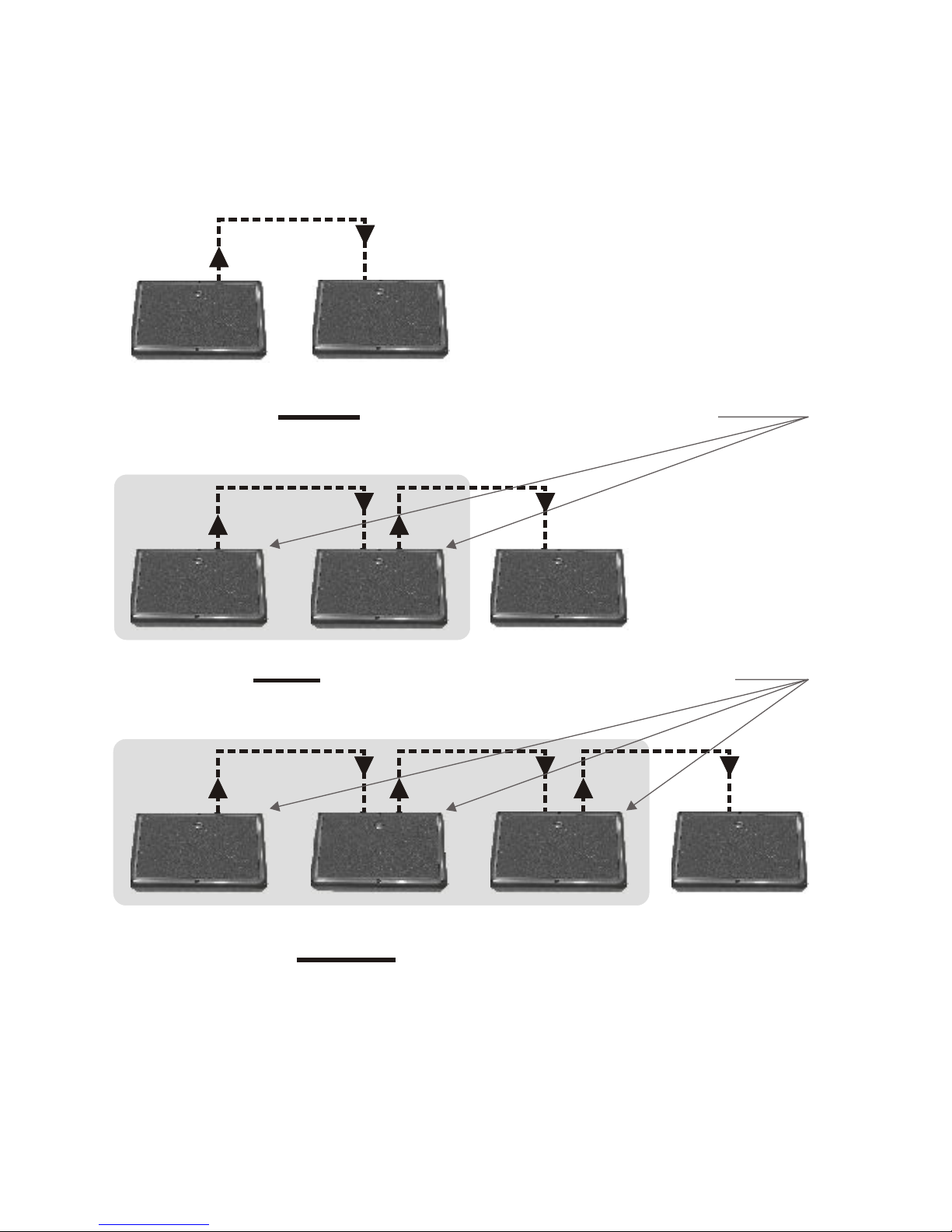
USING THE HOT SPOT WITH THE PA5X140
POWERED MONITOR
The PA5X140's SPEAKER OUTPUT jack is designed to allow a
maximum of two HOT SPOTS to be “daisy-chained” to it.
The PA5X140 produces 146 watts when powering two HOT
SPOTS (see figure below)
Route cables:
1) From the microphone to Galaxy Audio’s PA5X140.
2) From the output of the PA5X140 to the first HOT SPOT.
3) From the first HOT SPOT to the second HOT SPOT.
1 2 3
STAND MOUNTING
All HOT SPOT's, both powered and un-powered, have a built in
microphone stand mount: just slide the microphone stand into the
receptacle on the bottom of the HOT SPOT. Some microphone
stands may require an adaptor (contact any Galaxy Audio dealer
and ask for an SA-1, microphone stand adaptor).
Permanent piece and the collar will
not allow HOT SPOT to sit deep enough
Stands that need SA-1’s
K&M™ series stands
AKG™
Beyer™
Sennheiser™
Ultimate™
No SA-1 needed
stands
allow HOT SPOT to sit
deep enough on the stand
Atlas and SHURE
Stands that don’t
need SA-1’s
Atlas™
SHURE™
THE SA-1 WILL ALLOW YOU TO SECURELY PLACE
YOUR HOT SPOT ON ANY MICROPHONE STAND.
SA-1 needed
SA-1
Page 13

Page 11
MOUNTING YOUR MICRO SPOT SERIES SPEAKERS
The Micro Spot VC comes equipped with a stand mount bracket kit.
Wall mount options are available for the Micro Spot VC from any
Galaxy Audio dealer, or online at
Stand Mounting
To install the yoke bracket, attach the SA-1 to the yoke bracket
using the included ¼-20 hex bolt and washer as shown in picture
below (A.1). Tighten using a 7/16 wrench or socket. The yoke
bracket assembly can now be screwed on to the microphone
stand. Remove the two plastic threaded inserts from the T-nuts in
each side of the Micro Spot with a small flat blade screwdriver.
Place the Micro Spot into position so that the wing screws at the
ends of the yoke line up with the T-nuts in the cabinet. Tighten the
wing screws by hand.
www.galaxyaudio.com
(A.1)
(SA-1)
Stand Adaptor
Page 14

Page 12
SPECIFICATIONS
HOT SPOT HOT SPOT VC MICRO SPOT VC
1- 5” driver (S5N-16)
7.4
100 watts cont.
92 dB (1 kHz octave band)
150 Hz- 18 kHz
16 ohms
1/4” jacks
43.37
Fire Regardant Styrene
7”x 6”x 5.125”
(178mm x 152mm x 130mm)
2.7 lbs. (1.23kg)
volume control; range 18 dB
oz. (.21 kg)
2- 5” drivers (S5N-8)
14.8
200 watts cont.
98 dB (1 kHz octave band)
150 Hz- 18 kHz
16 ohms
1/4” jacks
28
ABS Plastic
6.75”x 10.94”x 6”
(171mm x 278mm x 152mm)
8.19 lbs. (3.72kg)
volume control; range 18 dB
oz. (.42 kg) total
2- 5” drivers (S5N-8)
14.8
200 watts cont.
98 dB (1 kHz octave band)
150 Hz- 18 kHz
16 ohms
1/4” jacks
28
ABS Plastic
6.75”x 10.94”x 6”
(171mm x 278mm x (52mm)
8.19 lbs. (3.72kg)
oz. (.42 kg) total
Speaker Compliment
Magnet Structure
Power Handling
Sensitivity (1 watt @ 1 meter)
Frequency Response
Nominal Impedance
Input Connections
SPLOWT
Enclosure
Dimensions
Net Weight
Additional Feature
The Galaxy Audio S5N-8 is ferro fluid cooled
Page 15

Page 13
The Galaxy Audio S5N-8 is ferro fluid cooled
PA5X140
1- 5” driver (S5N-8)
7.4
100 watts cont.
98 dB (1 kHz octave band)
150 Hz- 18 kHz
8 ohm
see amplifier section
9.12
Fire Retardant Styrene
6.75”x 10.94”x 6”
(171mm x 278mm x 152mm)
10.7 lbs. (4.85kg)
see amplifier section
oz. (.21 kg)
100 watts @ 8 ohms
146 watts @ 4 ohms
8 ohm < 0.05%
4 ohm < 0.1%
4 ohms
200 Hz- 20 kHz
three band center detent
LOW: +/-10 dB @ 300 Hz
MID: +/-10 dB @ 2 kHz
HIGH: +/-12 dB @ 16 kHz
one 1/4-inch balanced
one XLR 24V Phantom PWR
one 1/4-inch for 8 ohm load
one RCA line out
Speaker Compliment
Magnet Structure
Power Handling
Sensitivity (1 watt @
1 meter)
Frequency Response
Nominal Impedance
Input Connections
SPLOWT
Enclosure
Dimensions
Net Weight
Additional Feature
AMPLIFIER
Power Output
Distortion
Minimum Load
Frequency Response
Equalization
Input Connections
Output Connections
SPECIFICATIONS
Page 16

Page 14
This warranty gives you specific legal rights, and you may also have other rights which may vary
from state to state. This warranty is extended to the purchaser and to any purchaser from him for
value.
GALAXY AUDIO warrants the materials and workmanship of its products for a period of three
full years from the date of the original purchase.
The following are not covered by the warranty:
1. Damage to or deterioration of the exterior cabinet which occurs after delivery.
2. Damage after initial delivery resulting from accident, misuse or neglect.
3. Damage resulting from failure to follow instructions contained in the owner’s manual.
4. Damage resulting from the performance of repairs by someone other than GALAXY AUDIO
or an authorized GALAXY AUDIO service center.
5. Damage occurring during the shipment or delivery of any GALAXY AUDIO product to
GALAXY AUDIO or an authorized service center after initial delivery of the product to you.
6. Damage to any GALAXY AUDIO product which has been altered, or on which the serial
number has been effaced or removed.
If your unit requires service, it must be returned, shipping charges prepaid to an authorized
GALAXY AUDIO service center in the United States. (This warranty is not enforceable outside
the U.S.) If you are not able to locate an authorized service center in your area, please call or write
GALAXY AUDIO, 601 E.Pawnee, Wichita, Kansas 67211, (316) 263-2852. We will then refer
you to an authorized service center to which the unit may be returned, or we may advise you to
return your unit to the factory for service. Under no circumstances should you return your unit to
the factory without written instruction to do so. If service is required, you must present the
original or a copy of the bill of sale as a proof of date of purchase of your unit. Upon receipt of
your unit for service, GALAXY AUDIO or the authorized service center will repair or replace
your unit as soon as possible, but in no event later than 30 days after the receipt of the unit. We
will return the unit to you, shipping charges prepaid, provided the necessary repairs are covered
by this warranty. IMPLIED WARRANTIES OF MERCHANT ABILITY AND FITNESS FOR
PARTICULAR PURPOSE ARE LIMITED IN DURATION TO THE LENGTH OF THIS
WARRANTY, UNLESS OTHERWISE PROVIDED FOR BY STATE LAW. GALAXY
AUDIO’S LIABILITY IS LIMITED TO THE REPAIR OR REPLACEMENT, AT OUR OPTION,
OF ANY DEFECTIVE PRODUCT, AND SHALL IN NO EVENT INCLUDE INCIDENTAL OR
CONSEQUENTIAL DAMAGES OF ANY KIND.SOME STATES DO NOT ALLOW
LIMITATIONS ON HOW LONG AN IMPLIED WARRANTY LASTS AND/OR DO NOT
ALLOW THE EXCLUSION OR LIMITATION OFINCIDENTAL OR CONSEQUENTIAL
DAMAGES, SO THE ABOVE LIMITATIONS AND EXCLUSIONS MAY NOT APPLY TO
YOU.
GALAXY AUDIO does not authorize any third party, including any dealer or Authorized Service
Center, to assume any liability on behalf of GALAXY AUDIO or to make any warranty for
GALAXY AUDIO.
THREE YEAR LIMITED WARRANTY
Page 17

Page 15
GALAXY AUDIO
1-800-369-7768 www.galaxyaudio.com
P.O. BOX 16285 Wichita, Ks 67216-0285
Specifications in this manual are subject to change without notice.
Page 18

Page 16
GALAXY AUDIO
1-800-369-7768 www.galaxyaudio.com
P.O. BOX 16285 Wichita, Ks 67216-0285
Page 19

This Galaxy Audio product will be used for:
Live Sound o
Church o
Recording
Home/Project Studio o
Commercial Studio o
Post-Production/Mastering o
Broadcast
On-Air o
Production o
What magazines do you read?_________
_________________________________
_________________________________
__________________________________
_________________________________
_________________________________
How can Galaxy Audio better serve you?
_________________________________
_________________________________
_________________________________
_________________________________
__________________________________
_________________________________
Name________________________Phone_____________
Address________________________________________
City, State, Zip____________________________________
email_______________________
Dealer_______________________PurchaseDate________
Serial number Model
Registration
REGISTRATION CARD
Registration information is used ONLY by GALAXY
AUDIO and will be kept strictly confidential.
Page 20

PLACE
STAMP
HERE
GALAXY AUDIO
P.O. BOX 16285
WICHITA, KS 67216-0285
V1604
 Loading...