

Galaxy Audio HOT SPOT, HOT SPOT VC, POWERED HOT SPOT, MICRO SPOT VC, POWERED MICRO SPOT User Manual
Page 1
HOT SPOT, HOT SPOT VC,
MICRO SPOT VC, POWERED
HOT SPOT, POWERED MICRO SPOT
TABLE OF CONTENTS
IMPORTANT SAFETY INSTRUCTIONS......................................
BEFORE YOU BEGIN..................................................................
.............................................
SOUND REINFORCEMENT BASICS..........................................
HOT SPOT SERIES/MICRO SPOT VC.......................................
POWERED HOT SPOT/POWERED MICRO SPOT....................
USING THE PA5XD..................................................................
USING THE HOT SPOT WITH THE PA5XD............................
POWERED MICRO SPOT MSPA/MSPA-DC...............................
STAND MOUNTING.....................................................................
MOUNTING YOUR MICRO SPOT SERIES SPEAKERS............
SPECIFICATIONS........................................................................
WARRANTY..................................................................................
REGISTRATION...........................................................................
WELCOME...................................................................................
OHM’S LAW AND THE HOT SPOT
1
2
2
3
5
6
8
8
10
11
12
13
17
19
22
User Guide
®
®
Page 2
Page 1
IMPORTANT SAFETY INSTRUCTIONS
1.Read these instructions.
2.Keep these instructions.
3.Heed all warnings.
4.Follow all instructions.
5.Do not use this apparatus near water.
6.Clean only with dry cloth.
7.Do not block any ventilation openings. Install in accordance with the manufacturer's
instructions.
8.Do not install near any heat sources such as radiators, heat registers, stoves, or other
apparatus (including amplifiers) that produce heat.
9.Do not defeat the safety purpose of the polarized or grounding-type plug. A polarized
plug has two blades with one wider than the other. A grounding type plug has two
blades and a third grounding prong. The wide blade or the third prong are provided for
your safety. If the provided plug does not fit into your outlet, consult an electrician for
replacement of the obsolete outlet.
10.Protect the power cord from being walked on or pinched particularly at plugs,
convenience receptacles, and the point where they exit from the apparatus.
11.Only use attachments/accessories specified by the manufacturer.
12.Use only with the cart, stand, tripod, bracket, or table specified by the manufacturer, or
sold with the apparatus. When a cart is used, use caution when moving the
cart/apparatus combination to avoid injury from tip-over.
13.Unplug this apparatus during lightning storms or when unused for long periods of time.
14.Refer all servicing to qualified service personnel. Servicing is required when the
apparatus has been damaged in any way, such as power-supply cord or plug is
damaged, liquid has been spilled or objects have fallen into the apparatus, the
apparatus has been exposed to rain or moisture, does not operate normally, or has
been dropped.
15.Do not expose this apparatus to dripping or splashing and ensure that no objects filled
with liquids, such as vases, are placed on the apparatus.
16.To completely disconnect this apparatus from the AC Mains, disconnect the power
supply cord plug from the AC receptacle.
17.The mains plug of the power supply cord shall remain readily operable.
S3125A
The lightning flash with arrowhead symbol within an equilateral
triangle, is intended to alert the user to the presence of uninsulated
"dangerous voltage " within the product's enclosure that may be of
sufficient magnitude to constitute a risk of electric shock to persons.
The exclamation point within an equilateral triangle is intended to
alert the user to the presence of important operating and
maintenance (servicing) instructions in the literature accompanying
the product.
WARNING: To reduce the risk of fire or electric shock, do not
expose this apparatus to rain or moisture.
Page 3
Page 2
BEFORE YOU BEGIN
Before using this product be sure to read and understand all
instructions in this manual pertaining to the model(s) you have
purchased.
DO...
Read this manual
Use a unidirectional microphone
Handle with care
Complete the registration card at the back of the manual
DON’T...
Expose any unit covered in this manual to rain or moisture
Plug-in or unplug the HOT SPOT while it is operating
(doing so may damage your amplifier)
(call Galaxy Audio
for repairs). Failure to do so may void your warranty.
Attempt to make any repairs yourself
Welcome
Congratulations on your purchase of a Galaxy Audio Product!
Backed by over 25 years of proven real-world performance and a
3 year warranty, the product you have selected is one of the finest
personal monitoring devices available. Thank you for choosing
Galaxy Audio.
For full specifications of Galaxy Audio products,
visit www.galaxyaudio.com
Fill this out and retain for your records
Model:________________________________________
Serial number:__________________________________
Purchased from: ________________________________
Purchase date: _________________________________
To contact Galaxy Audio call 1-800-369-7768
write to P.O. BOX 16285 Wichita, Ks 67216-0285
or visit www.galaxyaudio.com
CAUTION: THESE PRODUCTS ARE CAPABLE OF PRODUCING
SOUND PRESSURE LEVELS WHICH MAY CAUSE PERMANENT
HEARING DAMAGE AFTER PROLONGED EXPOSURE.
Page 4

Page 3
Z=
Z x Z
1 2
Z + Z
1 2
Where Z1 is the impedance (or ohm rating) for the first speaker, Z2
for the second, and so on, for every speaker in the chain. This
equation calculates the total impedance of the speaker system,
which should NOT be lower than the minimum impedance rating of
the amplifier.
EXAMPLE 1:
For one pair of speakers use the short form of the equation: the
product of the two speakers divided by the sum of the two
speakers is equal to the total impedance or the equivalent
impedance of the speaker system.
Z(Total)=
1
1 1 1 1 1
___
+
___ ___ ___ ___
+ + +
Z Z Z Z
2 3 4 N
Z
1
OHM’S LAW AND THE HOT SPOT
All unpowered HOT SPOTS have a 16 ohm impedance, and like
most professional-type speakers have jacks which are wired in
parallel (meaning the signal can travel into one jack and out of the
other).Think of each speaker as a “load” added to the amplifier.
The greater the number of speakers, the heavier the load. Adding
too many speakers can overload the amplifier, causing it to
overheat and distort. If the amplifier begins to distort, or if it
becomes hot to the touch, disconnect any extra speakers. One
easy way to determine the load on the amplifier is to use Ohm’s
“
law, which states: “The total impedance of N speakers in parallel is
equal to the reciprocal of the sum of the reciprocals. In equation
form:
This equation may be used to calculate the equivalent impedance
for additional speakers in two-speaker increments. Determine the
impedance of the first two speakers, substitute Z total for Z , and
include the next speaker. Repeat the process until all speakers
have been included. The result should be the same as with the first
method. A word of caution: polarity rules must be observed when
connecting multiple speakers. Polarity will not affect the Z, but can
®
Page 5
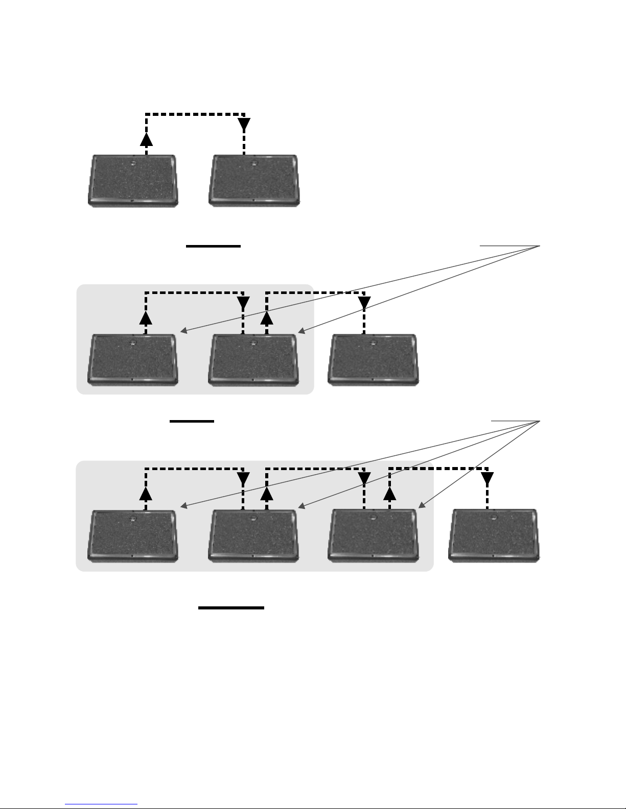
Z= = 8 Ohms for two HOT SPOTS
16 x 16
16 + 16
Z= = 5.33 Ohms for three HOT SPOTS
88 x 16
+ 16
Z= = 4 Ohms (the total load)
5.33
5.33
x 16
+ 16
Page 4
affect the quality and volume of the sound. If you are having
problems with any of these applications use Galaxy Audio’s
CRICKET Polarity and Continuity Test Set to check the polarity of
your cables.
EXAMPLE 2:
As long as all of the speakers have the same impedance rating, the
equivalent impedance of the system is the rated impedance of one
speaker divided by the number of equivalent speakers.
Page 6
Page 5
SOUND REINFORCEMENT BASICS
Avoiding feedback
Feedback (the shriek sometimes emitted by PA systems) occurs
when the microphone (or pickup) and speaker are positioned too
close together for a given level of volume. Once feed back occurs,
it will continue until either the volume is decreased or the
microphone or speaker is moved. Gain is the degree to which the
volume may be turned up before feedback begins. In setting up a
sound system, the objective is to maximize gain.
Monitor Placement
HOT SPOT Monitors should be positioned within arm's
reach of the performer.
Monitors should be placed to the rear of the
microphone being used by the performer.
Avoiding Distortion
Distortion in a monitor system usually occurs when the amplifier is
being over-driven, nearing the limits of its power output capability.
Over-driving the amplifier may be corrected by reducing the bass
frequencies in the monitor mix (low notes use a lot of power).
Since the HOT SPOT NEOLITE driver will not reproduce tones
lower than 200 Hz, reduce the low frequencies if the speaker
begins to distort. Distortion may also originate with a bad signal
source.
NEO DRIVER
Introduced in 2004, the NEOLITE driver is a state of the art
controlled bandwidth speaker that is included in all products
covered in this manual with the exception of the MSPA/MSPA-DC.
Tailored to reproduce a frequency range from 150 Hz-18 kHz, the
NEOLITE is manufactured with the rare earth element Neodymium
that has an extremely intense magnetic field in comparison to its
weight. This magnetic field is also very concentrated, allowing the
speaker to be placed near sensitive equipment that may be
affected by a strong magnetic force, such as a TV or a computer
monitor.
®
®
®
Page 7
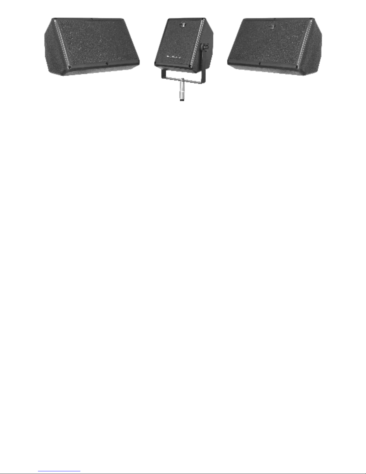
HOT SPOT SERIES/MICRO SPOT VC
HSRG/HSVC The HOT SPOT was created as the solution to the
problem of musicians and public speakers not being able to hear
themselves while performing. The HOT SPOT's design is
unsurpassed in efficiently reproducing the crucial vocal range
frequencies.
Each Hot Spot comes with a built in stand mount that allows the
unit to be placed on nearly any microphone stand, close to the
performer, for true near field vocal monitoring (some microphone
stands may require the optional stand adaptor SA-1)
The Hot Spot VC (HSVC) comes with a volume control that not
only affects the volume of the unit, but also the impedance of the
unit. (See chart [T.1] pg.7 for more information about the volume
control).
MSVC
Like the Hot Spot series, the Micro Spot VC is also tailored to the
vocal frequencies. The Micro Spot can be mounted to a
microphone stand using the included yoke bracket kit. For
information regarding the bracket kit see, MOUNTING YOUR
MICRO SPOT SERIES SPEAKERS. [A.1]( )
Like the Hot Spot VC, the Micro Spot VC is also equipped with a
volume control. (Please refer to table [ ] pg. 7 for information
regarding the positions on the volume control).
pg. 13
T.1
Page 6
®
Page 8
POSITION
Full Clockwise
2nd
3rd
4th
5th
6th
7th
IMPEDANCE
16 ohms
23 ohms
33 ohms
46 ohms
64 ohms
90 ohms
130 ohms
dB REDUCTION
0
-3
-6
-9
-12
-15
-18
The HOT SPOT VC and
The impedance of the HOT SPOT VC and MICRO SPOT VC is determined by
the position of its volume control. Use the table below to determine the actual
impedance.
MICRO SPOT VC
Page 7
[T.1]
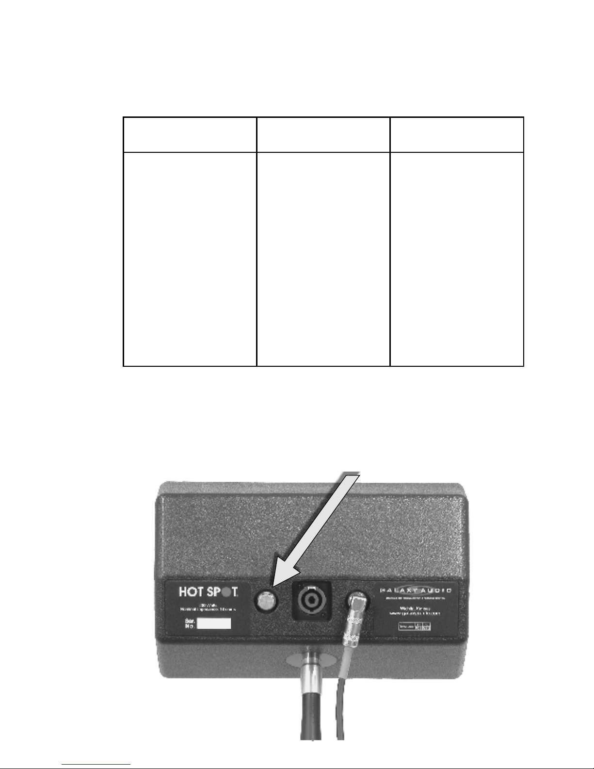
Note: Each Hot Spot VC comes equipped with a Speakon and two 1/4"
speaker jacks, all of which are wired in parallel to allow easy "daisy chaining'
of multiple Hot Spots. The aluminum screw-on jack caps on the 1/4" jacks
should remain in place when those jacks are not in use to keep the cabinet
airtight and to avoid any unwanted "whistling"
®
Page 9

Page 8
POWERED HOT SPOT/POWERED MICRO SPOT
FEATURES OF GALAXY AUDIO'S POWERED SPEAKERS
•PA5XD (CUL Listed), MSPA/MSPA-DC (CSA US listed)
•Black cast aluminum faceplate (used as an integral heat sink)
•Fire-retardant styrene plastic outer shell
•SmartALIC (PA5XD only) input circuitry automatically
distinguishes between microphone and line level signals without
having to flip a switch.
Using the PA5XD as a...
Powered Monitor
When connected to a mixer’s monitor output or auxiliary output, the
PA5XD enables each performer to create his/her own monitor mix.
Additional monitors can be attached to the PA5XD’s speaker output.
A recorder can be attached to the PA5XD’s LINE output.
Virtually any type of signal (instrument, mic level from a mixing
console, guitar, keyboard, tape player or condenser mic can be
plugged into the PA5XD inputs.
Ultra-Compact PA System
The PA5XD by itself is a one-piece PA system. Simply plug in a mic
or instrument for 100 watts of sound reinforcement power.
When two 16 ohm Galaxy Audio HOT SPOT personal monitors are
attached to the SPEAKER OUTPUT, the PA5XD’s power output
increases to 146 watts. Whether using the HOT SPOT or another
speaker, the PA5XD’s power output depends on the impedance of
the speakers being powered. The load on the PA5XD's amplifier
section must greater than or equal to 4 ohms. Anything less will
overload the amplifier.
Practice Amp
A balanced signal from a microphone or second instrument may be
fed into one input while an instrument, CD player or tape deck is fed
into the other.
®
Page 10
Page 9
CAUTION
RISK OF ELECTRIC SHOCK
DO NOT OPEN
CAUTION: TO REDUCE THE RISK OF FIRE OR ELECTRICAL
SHOCK,DO NOT EXPOSE THIS EQUIPMENT TO RAIN OR MOISTURE
AVIS: RISQUE DE CHOC ELECTRIQUE NE PAS OUVRIR
C RE PA5 140O X
1 2 3 4
02
03 04 0512111098765
SPEAKER OUTPUT
73W 8ohms Min.
60HZ 250W
120V
~
50HZ 250W
230V
~
LINE OUT
SERIAL NO.
93FL
COMMERCIAL
AUDIO EQUIPMENT
601 E. Pawnee Wichita, KS 67211
316.263.2852 www.galaxyaudio.com
7
7
GA LAXY AUD IO
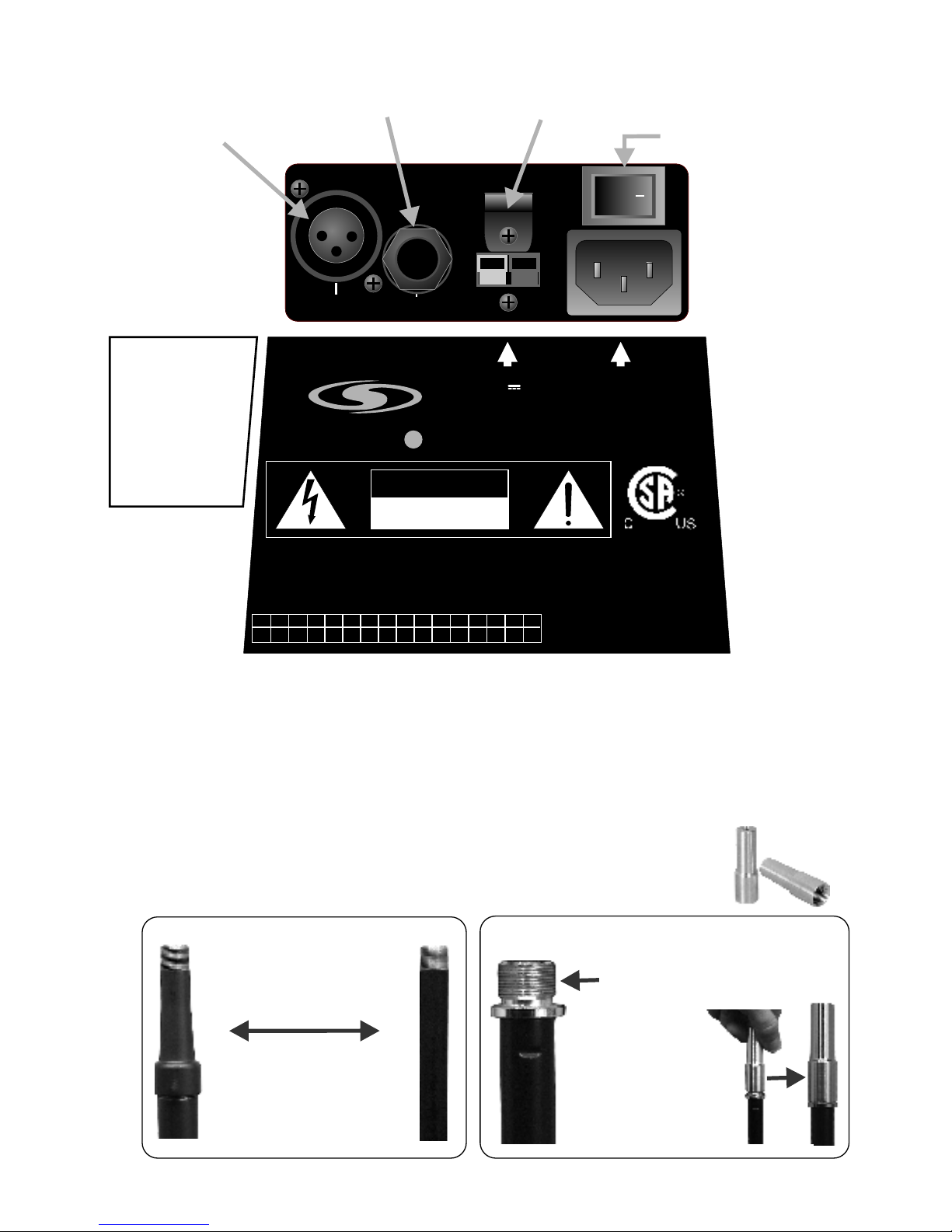
SPEAKER OUTPUT
1/4” connector output from the internal amplifier.
It can supply an external 8 ohm speaker with 73
watts of RMS power. This means two 16 ohm
HOT SPOTS can be connected to the system
without overloading the amplifier; great for a small
PA or monitor setup.
LINE OUT
RCA jack -10dB line level output
can be fed to a recorder, or to other
sound system components. It is
post-EQ, pre-compressor and
pre-amplifier.
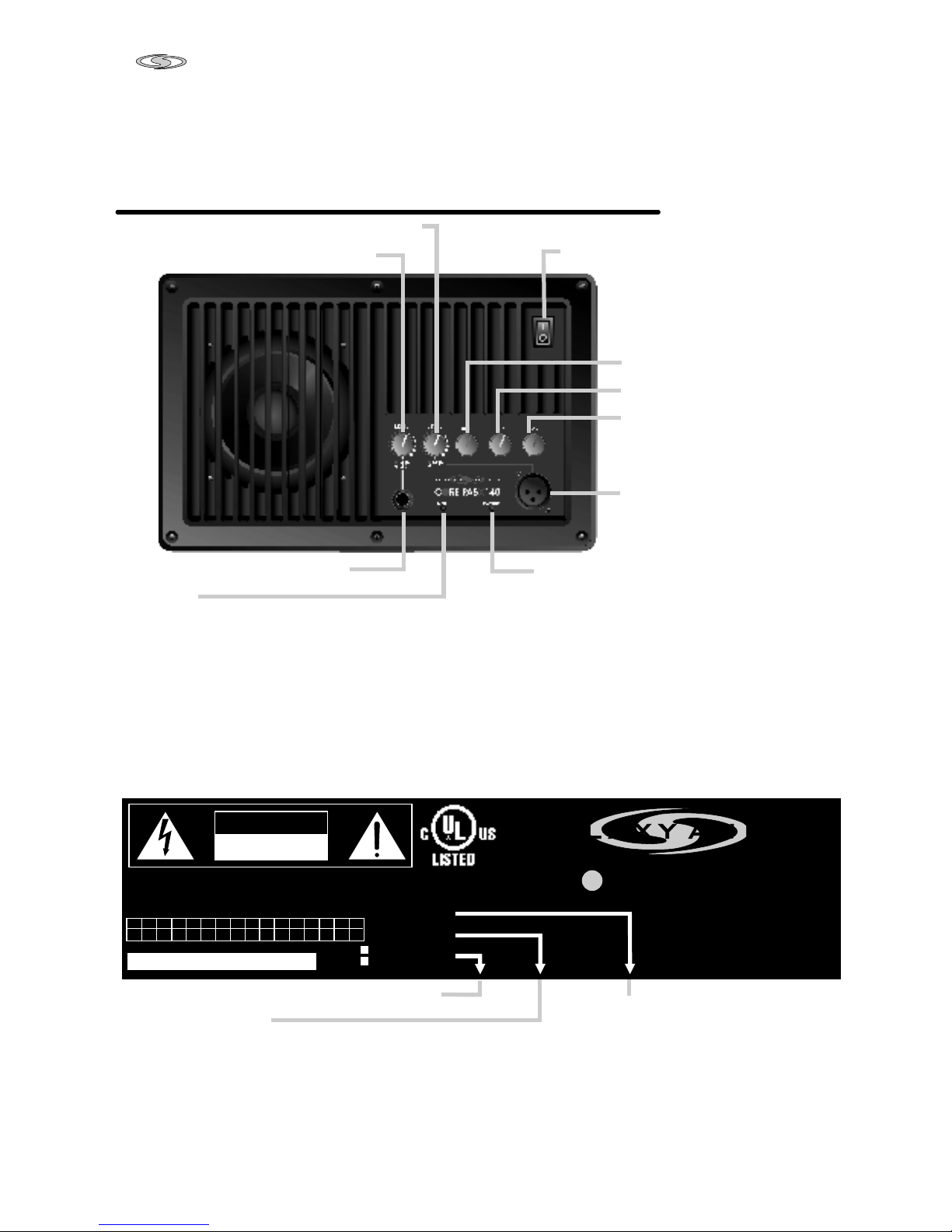
CONNECTORS/INDICATORS and their operation
(Rear Panel)
POWER CORD
Effects devices for microphones or a second instrument may be fed
into one input while an instrument, CD player or tape deck is
fed into the other.
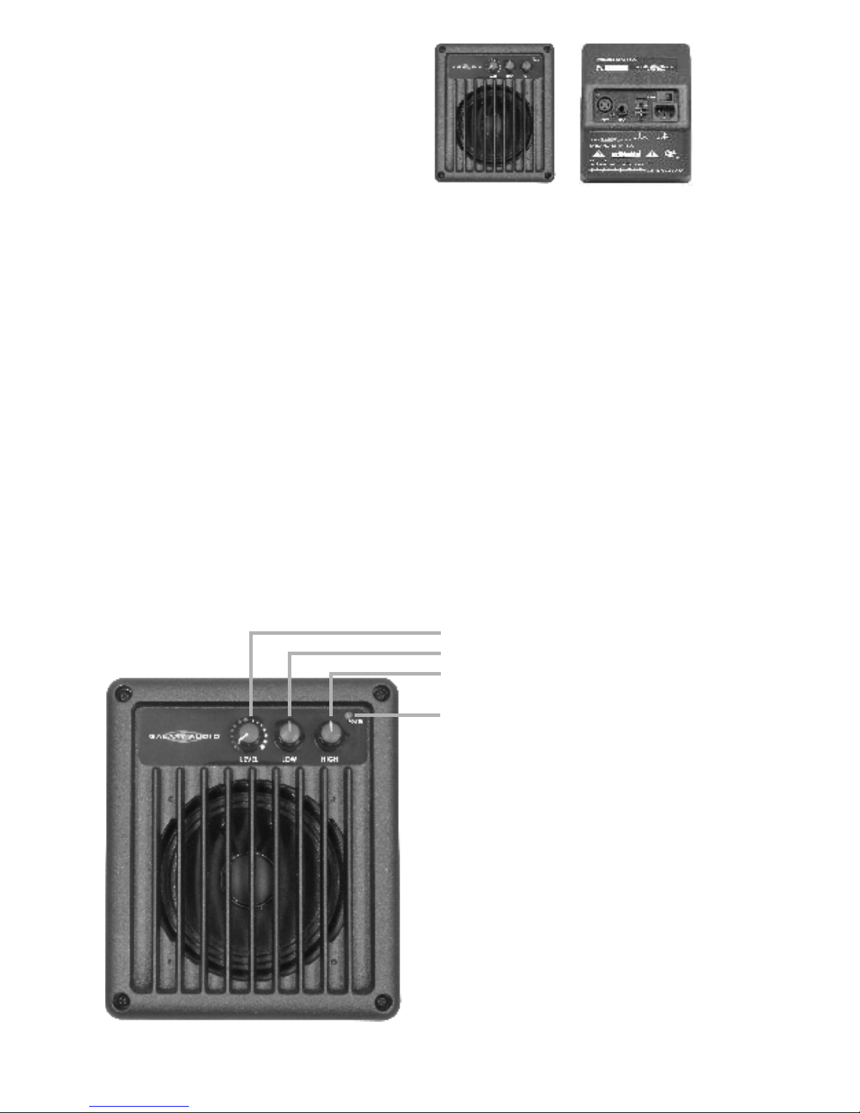
POWER SWITCH
TONE CONTROLS
When all three controls are set to
the 12 o’clock (detent) position,
the output frequency response is flat.
MIC (XLR) INPUT
Balanced input with 24 VDC
phantom power for electret
microphones.
POWER LED
LIMIT LED
Indicates when the built-in compression circuit is activated. By automatically reducing gain before clipping occurs the
compression circuit prevents distortion. The LIMIT LED remains lit about half the time when the amplifier is being driven
to its maximum potential. Do not allow it to remain lit more than half the time.
HIGH +/- 12dB shelving at 15 kHz
MID +/- 10dB peak/dip at 2 kHz
LOW +/- 10dB peak/dip at 300 Hz
The PA5X (POWERED HOT SPOT)
CONTROLS/INDICATORS and their operation (Front Panel)
D
LEVEL CONTROL FOR MIC (XLR) INPUT
LEVEL CONTROL FOR 1/4" INPUT
1/4" INPUT
Page 11

Page 10
USING THE HOT SPOT WITH THE PA5XD
POWERED MONITOR
The PA5XD’s SPEAKER OUTPUT jack is designed to allow a
maximum of two HOT SPOTS to be “daisy-chained” to it.
The PA5XD produces 146 watts when powering two HOT
SPOTS (see figure below)
Route cables:
1) From the microphone to Galaxy Audio’s PA5XD.
2) From the output of the PA5XD to the first HOT SPOT.
3) From the first HOT SPOT to the second HOT SPOT.
1 2 3
®
Page 12
Page 11
POWERED
MICRO SPOT
MS
The MSPA is similar to the Powered Hot Spot, with one major difference;
it's half the size! The MSPA has a 30 watt amplifier, with a universal
power supply. That means this unit can be used anywhere in the world
as it will function on 90-250 VAC (volts AC) at 50/60 Hz. The MSPA
delivers full frequency fidelity thanks to its full range 4.5” speaker.
In addition to the standard AC input, MSPA-DC comes equipped with a
12volt DC input. When AC power is not available, the MSPA-DC can be
plugged into a car's cigarette lighter, or attached directly to a 12 volt
battery using an approved type cable.
For information regarding stand or wall mounting, see MOUNTING
YOUR MICRO SPOT SERIES SPEAKERS. (Page. 13)
CONTROLS/INDICATORS
PA/MSPA-DC
and their operation (Front Panel)
POWER LED
LEVEL CONTROL (for both Inputs)
LOW +/- 12 dB @ 200 Hz
HIGH +/- 12 dB @ 10 kHz
Page 13
Page 12
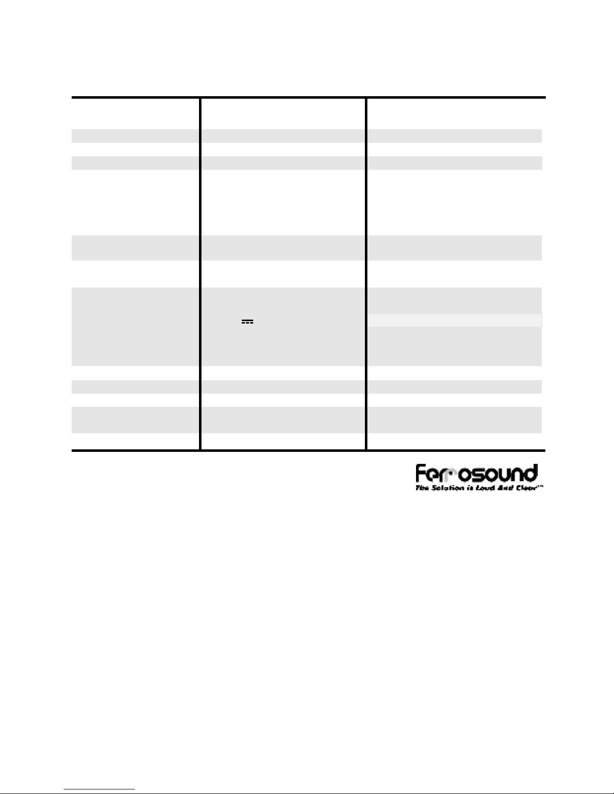
STAND MOUNTING
All HOT SPOT's, both powered and un-powered, have a built in
microphone stand mount: just slide the microphone stand into the
receptacle on the bottom of the HOT SPOT. Some microphone
stands may require an adaptor (contact any Galaxy Audio dealer
and ask for an SA-1, microphone stand adaptor).
LINE
MIC
POWER
Permanent piece and the collar will
not allow HOT SPOT to sit deep enough
Stands that need SA-1’s
K&M™ series stands
AKG™
Beyer™
Sennheiser™
Ultimate™
No SA-1 needed
Atlas and SHURE stands
allow HOT SPOT to sit
deep enough on the stand
Stands that don’t
need SA-1’s
Atlas™
SHURE™
THE SA-1 WILL ALLOW YOU TO SECURELY PLACE
YOUR HOT SPOT ON ANY MICROPHONE STAND.
SA-1 needed
SA-1
A
A
LINE LEVEL
1/4" INPUT
SAFETY
CABLE CLIP
MIC LEVEL
XLR INPUT
POWER SWITCH
CONTROLS/INDICATORS and their operation (Rear Panel)
CAUTION
RISK OF ELECTRIC SHOCK
DO NOT OPEN
CAUTION: TO REDUCE THE RISK OF FIRE OR ELECTRICAL
SHOCK,DO NOT EXPOSE THIS EQUIPMENT TO RAIN OR MOISTURE
AVIS: RISQUE DE CHOC ELECTRIQUE NE PAS OUVRIR
1 2 3 4
05
06 07 0812111098765
MICRO SP T PA-DCO
601 E. Pawnee Wichita, KS 67211
316.263.2852 www.galaxyaudio.com
GALAXY AUDIO
DC INPUT
12Vdc , 3A
AC INPUT
90 - 250 Vac~
50/60 Hz, 30W
MSPA-DC
label shown
MSPA
label
excludes
DC input
Page 14

Page 13
MOUNTING YOUR MICRO SPOT SERIES SPEAKERS
The Micro Spot VC comes equipped with a stand mount bracket kit,
while the Powered Micro Spot is supplied with a bracket kit that
allows either stand or wall mounting. Wall mount options are
available for the Micro Spot VC from any Galaxy Audio dealer, or
online at
Stand Mounting
To install the yoke bracket, attach the SA-1 to the yoke bracket
using the included ¼-20 hex bolt and washer as shown in picture
below (A.1). Tighten using a 7/16 wrench or socket. The yoke
bracket assembly can now be screwed on to the microphone
stand. Remove the two plastic threaded inserts from the T-nuts in
each side of the Micro Spot with a small flat blade screwdriver.
Place the Micro Spot into position so that the wing screws at the
ends of the yoke line up with the T-nuts in the cabinet. Tighten the
wing screws by hand.
www.galaxyaudio.com
(A.1)
(SA-1)
Stand Adaptor
Page 15

Page 14
WALL/CEILING MOUNTING
Galaxy Audio yoke brackets can be used for permanently
mounting HOT SPOT, MICRO SPOT, and CHAMELEON
loudspeakers to walls and ceilings. The mounting angle can be
adjusted by simply loosening the wing screws at either end of the
yoke and by loosening the bolt where the yoke mounts to the wall
plate. These brackets should be used only on a flat, secure, and
stable surface.
PRECAUTIONS:
Whenever an object is affixed to a wall or ceiling, you must take
special care to mount it securely to prevent it from falling and
causing damage or injury.
MOUNTING SURFACES: Carefully examine the composition,
construction and strength of the surface you are mounting to. Be
sure to provide adequate reinforcement should you deem it
necessary. You must also consider what type of hardware and
what type of mounting techniques are appropriate for each
mounting surface.
FASTENERS: Attaching the bracket requires fasteners selected
for the strength and composition of the mounting surfaces
involved. Whatever fastener is selected, it should be no smaller
than a #8 screw or 1/4" bolt. When drilling pilot holes be sure that
the holes are smaller than the core diameter of the screw. Always
use fasteners in all mounting holes and avoid over tightening, as
this can weaken the mounting surface, damage the fasteners, and
make the installation much less secure.
SECONDARY SUPPORT: As we recommend the use of a
secondary support for added safety, each yoke bracket is
equipped with a safety cable. When properly installed it provides
secondary support without inhibiting the adjustment of the bracket,
and can be easily hidden out of sight.
Page 16

Page 15
MOUNTING PROCEDURE:
PREVIEW: After evaluating the mounting surfaces and obtaining
the appropriate fasteners, the installation will consist of the
following steps, in order:
1. Mounting the bracket plate to the wall or ceiling.
2. Bolting the yoke to the plate.
3. Joining the cabinet with the bracket assembly.
4. Installing the safety cable.
5. Adjusting the speaker position and tightening the yoke
bolt and wing screws.
TOOLS REQUIRED: You will need at least these tools for
installation:
7/16" box end wrench
large crimping pliers
tools to secure the fasteners selected for the bracket
assembly (drill, screwdrivers, etc.)
carpenter's level for precise positioning of the speaker.
(optional)
Note: It is often helpful to have another person available to
hold the speaker in place during the tightening procedure.
INSTALLATION:
ATTACHING THE BRACKET ASSEMBLY TO THE MOUNTING
SURFACE:
Position the bracket assembly onto the wall or ceiling at the
location you have selected, preferably to a stud, joist or other
structural member rather than only to drywall or other nonstructural material. Make sure there will be enough clearance to
rotate and tilt the speaker to the desired angle. Using the base
plate of the bracket assembly as a template, mark the four hole
locations.
NOTE: Check that any holes you drill and the fasteners will
not interfere with any wiring, plumbing, etc. that may be
behind the mounting surface.
Prepare the mounting surface and the four holes for the fasteners.
Page 17

Page 16
Pull speaker wires through the mounting surface and the feed thru
the hole in the bracket. Secure the bracket base plate. Do not
over tighten fasteners! Bolt the yoke to the base plate and tighten
with a 7/16" box end wrench.
JOINING THE CABINET TO THE BRACKET ASSEMBLY:
Remove the two plastic threaded inserts from the T-nuts with a
small flat blade screwdriver. Lift the speaker into position so that
the wing screws at the ends of the yoke line up with the T-nuts in
the cabinets. Tighten the wing screws by hand.
SECURING THE SAFETY CABLE:
Slip the loose end of the safety cable through the cable clamp
located at the back of the cabinet. Bring the cable back through
the crimp sleeve and firmly crimp the sleeve with a large pair of
crimping pliers.
ADJUSTMENT:
Loosen the yoke bolt just enough to slide or rotate the yoke to the
desired position. Tighten the yoke bolt securely with a 7/16" box
end wrench. If necessary loosen the wing screws and tilt the Hot
Spot to the desired position. Re-tighten the wing screws firmly by
hand. After a few minutes check the assembly for any slippage
and re-tighten. Connect the speaker wires and the installation is
complete.
Page 18

SPECIFICATIONS
HOT SPOT HOT SPOT VC MICRO SPOT VC
1- 5” driver (S5N-16)
7.4
100 watts cont.
92 dB (1 kHz octave band)
300 Hz- 15 kHz
16 ohms
1/4” jacks
43.37
Fire Retardant Styrene
7”x 6”x 5.125”
(178mm x 152mm x 130mm)
2.7 lbs. (1.23kg)
volume control; range 18 dB
oz. (.21 kg)
2- 5” drivers (S5N-8)
14.8
200 watts cont.
92 dB (1 kHz octave band)
250 Hz- 15 kHz
16 ohms
®
1/4” jacks, Speakon (in parallel)
28
ABS Plastic
6.75”x 10.94”x 6”
(171mm x 278mm x 152mm)
4.5 lbs. (2.04kg)
volume control; range 18 dB
oz. (.42 kg) total
2- 5” drivers (S5N-8)
14.8
200 watts cont.
92 dB (1 kHz octave band)
250 Hz- 15 kHz
16 ohms
®
1/4” jacks, Speakon (in parallel)
28
ABS Plastic
6.75”x 10.94”x 6”
(171mm x 278mm x (152mm)
4.5 lbs. (2.04kg)
oz. (.42 kg) total
Speaker Compliment
Magnet Structure
Power Handling
Sensitivity (1 watt @ 1 meter)
Frequency Response
Nominal Impedance
Input Connections
*SPLOWT
Enclosure
Dimensions
Net Weight
Additional Feature
Page 17
*Splowt A unit of measure, expressed as dB, that divides a speaker's maximum
SPL by its weight in pounds. Galaxy Audio's MICRO SPOT boasts a splowt of
43 dB (highest in the known universe).
The Galaxy Audio S5N-8 and S5N-16
are ferro fluid cooled drivers.
®
®
Page 19
Page 18
The Galaxy Audio S5N-8 and S5N-16
are ferro fluid cooled drivers.
SPECIFICATIONS
MSPA/MSPA-DC PA5XD
1- 4.5” driver, 4 ohms
21
Fire Retardant Styrene
7”x 6”x 5.125”
(178mm x 152mm x 130mm)
4.82 lbs. (2.19kg)
1- 5” driver (S5N-8), 8 ohms
9.12
Fire Retardant Styrene
6.75”x 10.94”x 6”
(171mm x 278mm x 152mm)
10.7 lbs. (4.85kg)
100 watts @ 8 ohms
146 watts @ 4 ohms
8
ohm < 0.05%, 4 ohm < 0.1%
4 ohms
300 Hz- 15 kHz
three band center detent
LOW: +/-10 dB @ 300 Hz
MID: +/-10 dB @ 2 kHz
HIGH: +/-12 dB @ 15 kHz
one 1/4-inch balanced
one XLR 24V Phantom PWR
one 1/4-inch for 8 ohm load
one RCA line out
DOMESTIC: 120Vac 60Hz
EXPORT: 230Vac 50Hz
~
~
Power Output
Distortion
Minimum Load
Frequency Response
Equalization
Input Connections
Output Connections
Power Requirements
Speaker Compliment
*SPLOWT
Enclosure
Dimensions
Net Weight
30 watts @ 4 ohms
<0.5% @ 4 ohms
4 ohms
150 Hz- 15 kHz
Two band center detent
LOW: +/-12 dB @ 200 Hz
HIGH: +/-12 dB @ 10 kHz
one 1/4-inch balanced
one XLR w/+15VDC Phantom
MSPA-DC
90-250 Vac~ 50/60 Hz, 30W
12Vdc , 3A
MSPA
90-250 Vac~ 50/60 Hz, 30W
*Splowt A unit of measure, expressed as dB, that divides a speaker's maximum
SPL by its weight in pounds. Galaxy Audio's MICRO SPOT boasts a splowt of
43 dB (highest in the known universe).
Page 20

Page 19
This warranty gives you specific legal rights, and you may also have other rights which may vary
from state to state. This warranty is extended to the purchaser and to any purchaser from him for
value.
GALAXY AUDIO warrants the materials and workmanship of its products for a period of three
full years from the date of the original purchase.
The following are not covered by the warranty:
1. Damage to or deterioration of the exterior cabinet which occurs after delivery.
2. Damage after initial delivery resulting from accident, misuse or neglect.
3. Damage resulting from failure to follow instructions contained in the owner’s manual.
4. Damage resulting from the performance of repairs by someone other than GALAXY AUDIO
or an authorized GALAXY AUDIO service center.
5. Damage occurring during the shipment or delivery of any GALAXY AUDIO product to
GALAXY AUDIO or an authorized service center after initial delivery of the product to you.
6. Damage to any GALAXY AUDIO product which has been altered, or on which the serial
number has been effaced or removed.
If your unit requires service, it must be returned, shipping charges prepaid to an authorized
GALAXY AUDIO service center in the United States. (This warranty is not enforceable outside
the U.S.) If you are not able to locate an authorized service center in your area, please call or write
GALAXY AUDIO, 601 E.Pawnee, Wichita, Kansas 67211, (316) 263-2852. We will then refer
you to an authorized service center to which the unit may be returned, or we may advise you to
return your unit to the factory for service. Under no circumstances should you return your unit to
the factory without written instruction to do so. If service is required, you must present the
original or a copy of the bill of sale as a proof of date of purchase of your unit. Upon receipt of
your unit for service, GALAXY AUDIO or the authorized service center will repair or replace
your unit as soon as possible, but in no event later than 30 days after the receipt of the unit. We
will return the unit to you, shipping charges prepaid, provided the necessary repairs are covered
by this warranty. IMPLIED WARRANTIES OF MERCHANT ABILITY AND FITNESS FOR
PARTICULAR PURPOSE ARE LIMITED IN DURATION TO THE LENGTH OF THIS
WARRANTY, UNLESS OTHERWISE PROVIDED FOR BY STATE LAW. GALAXY
AUDIO’S LIABILITY IS LIMITED TO THE REPAIR OR REPLACEMENT, AT OUR OPTION,
OF ANY DEFECTIVE PRODUCT, AND SHALL IN NO EVENT INCLUDE INCIDENTAL OR
CONSEQUENTIAL DAMAGES OF ANY KIND.SOME STATES DO NOT ALLOW
LIMITATIONS ON HOW LONG AN IMPLIED WARRANTY LASTS AND/OR DO NOT
ALLOW THE EXCLUSION OR LIMITATION OFINCIDENTAL OR CONSEQUENTIAL
DAMAGES, SO THE ABOVE LIMITATIONS AND EXCLUSIONS MAY NOT APPLY TO
YOU.
GALAXY AUDIO does not authorize any third party, including any dealer or Authorized Service
Center, to assume any liability on behalf of GALAXY AUDIO or to make any warranty for
GALAXY AUDIO.
THREE YEAR LIMITED WARRANTY
Page 21

1-800-369-7768 www.galaxyaudio.com
P.O. BOX 16285 Wichita, Ks 67216-0285
Page 20
®
Four rubber feet are included for those of you
using the HOT SPOT or HOT SPOT VC with
the TWIST LOCK connector and as a stand
alone wedge speaker.
These rubber feet allow for extra room for the
Speakon connector and its cable.
Page 22

V81407
1-800-369-7768 www.galaxyaudio.com
P.O. BOX 16285 Wichita, Ks 67216-0285
Specifications in this manual are subject to change without notice.
Page 21
Page 23

This Galaxy Audio product will be used for:
Live Sound o
Church o
Recording
Home/Project Studio o
Commercial Studio o
Post-Production/Mastering o
Broadcast
On-Air o
Production o
What magazines do you read?_________
_________________________________
_________________________________
__________________________________
_________________________________
_________________________________
How can Galaxy Audio better serve you?
_________________________________
_________________________________
_________________________________
_________________________________
__________________________________
_________________________________
Name________________________Phone_____________
Address________________________________________
City, State, Zip____________________________________
email_______________________
Dealer_______________________PurchaseDate________
Serial number Model
Registration
REGISTRATION CARD
Registration information is used ONLY by GALAXY
AUDIO and will be kept strictly confidential.
Page 24

PLACE
STAMP
HERE
GALAXY AUDIO
P.O. BOX 16285
WICHITA, KS 67216-0285
 Loading...