

Page 1
GAL A X Y AUDIO Quick Start Guide
EDX
Wireless Microphone System
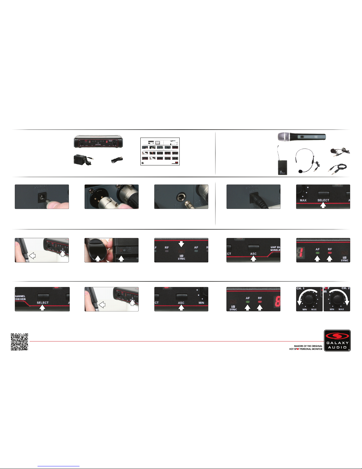
Included Components
1. EDX Receiver x1
3. Power Supply x1
4. Quick Start Guide x1
2. 1/4" Cable x1
1.
2 3 2
Setup
1
With the transmitter for channel 1 turned
on, place the transmitter with it’s IR
window facing the receiver IR window,
about 6" away.
3a
When the transmitter is synced, the red
RF light on channel 1 will illuminate.
When talking into the microphone the
green AF light will illuminate.
3
4.
2.
Insert the 5.5 mm plug into the DC
input jack, then plug the wall wart into a
120VAC outlet.
Press the “Select” button on channel 1
to choose a frequency number of 0-9
or A-F.
Make sure the receiver is powered on.
(Powers on immediately when power
supply is plugged into the DC input jack)
Combined Output: 1/4" - Connect 1 end
of a shielded 1/4"M to 1/4"M cable to the
1/4" mix output, then connect the other
end into your system input.
Individual Outputs: Connect a shielded
microphone cable to each channel’s
XLRM output, then connect the other
end into your mixer input.
4.
3.
Operation
1
43b
5
Optional Accessories
1. HH38 Handheld Mic
3. HS13-UBK Headset Mic
4. LV-13BK Lav Mic
AS-GTRVE Guitar Cable5.
2. MBP38 Body Pack
1.
2.
For detailed instructions for finding the best frequencies, please consult the online manual.
7
With the transmitter for channel 2 turned
on, place the transmitter with it’s IR
window facing the receiver IR window,
about 6" away.
8
Press the ASC button on channel 2.
9
3.
5.
6
Press the ASC button on channel 1.
Press the “Select” button on channel 2
to choose a frequency number of 0-9
or A-F
Use the individual channel level controls
to adjust the volume of the channels.
These affect both the individual as well
as the combined outputs.
10
When the transmitter is synced, the red
RF light on channel 2 will illuminate.
When talking into the microphone the
green AF light will illuminate.
GALAX Y AUDIO Quick Start Guide
EDX
Wireless Microphone System
Included Components
1. EDX Receiver x1
3. Power Supply x1
4. Quick Start Guide x1
2. 1/4" Cable x1
1.
2 3 2
Setup
1
With the transmitter for channel 1 turned
on, place the transmitter with it’s IR
window facing the receiver IR window,
about 6" away.
3a
When the transmitter is synced, the red
RF light on channel 1 will illuminate.
When talking into the microphone the
green AF light will illuminate.
3
4.
2.
Insert the 5.5 mm plug into the DC
input jack, then plug the wall wart into a
120VAC outlet.
Press the “Select” button on channel 1
to choose a frequency number of 0-9
or A-F.
Make sure the receiver is powered on.
(Powers on immediately when power
supply is plugged into the DC input jack)
Combined Output: 1/4" - Connect 1 end
of a shielded 1/4"M to 1/4"M cable to the
1/4" mix output, then connect the other
end into your system input.
Individual Outputs: Connect a shielded
microphone cable to each channel’s
XLRM output, then connect the other
end into your mixer input.
4.
3.
Operation
1
43b
5
Optional Accessories
1. HH38 Handheld Mic
3. HS13-UBK Headset Mic
4. LV-13BK Lav Mic
AS-GTRVE Guitar Cable5.
2. MBP38 Body Pack
1.
2.
For detailed instructions for finding the best frequencies, please consult the online manual.
7
With the transmitter for channel 2 turned
on, place the transmitter with it’s IR
window facing the receiver IR window,
about 6" away.
8
Press the ASC button on channel 2.
9
3.
5.
6
Press the ASC button on channel 1.
Press the “Select” button on channel 2
to choose a frequency number of 0-9
or A-F
Use the individual channel level controls
to adjust the volume of the channels.
These affect both the individual as well
as the combined outputs.
10
When the transmitter is synced, the red
RF light on channel 2 will illuminate.
When talking into the microphone the
green AF light will illuminate.
Transmitter IR Window Locations:
Handheld IR is located on the end.
Body Pack IR is located inside the
battery compartment.
Receiver IR Window Location:
Center of the receiver face
Page 2
3. Q. Which setting do I use on the body pack transmitter?
A. For a headset or lapel microphone use “MIC”, for a line level input use “0dB” and for a guitar use “-10dB”.
Specifications subject to change without notice.
V20160317
601 E. Pawnee Wichita, KS 67211 316. 263.2852 FAX 316.263.0642 www.galaxyaudio.com
Distributed in Canada by Audio Distributors International (ADI) 1275 Newton, unit 6 Boucherville, QC J4B 5H2 Canada
450.449.8177 FAX 450.449.8180
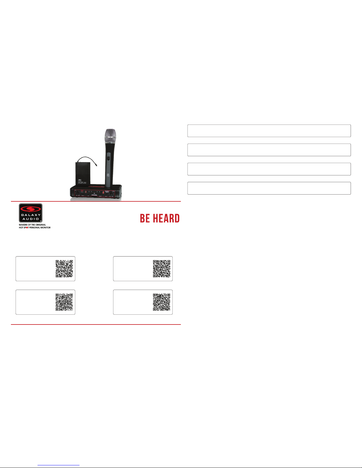
Other Helpful Sources
EDX
Manual
(PDF Download)
EDX
Product Page
EDX
Cutsheet
(PDF Download)
EDX
How To Video
Quick Start Guide
EDX
Wireless Microphone System
TM
FAQ
1. Q. I’m having problems finding the best frequency for me. Where do I go to find this information?
A. Please consult the online manual or visit: GalaxyAudio.com/support/schematics-and-frequency-charts
2. Q. With my transmitter off, the RF and AF lights are both on, and I get a lot of noise.
A. You are picking up outside interference and you need to change your frequency.
Printed in China
4. Q. My handheld microphone is much louder than my lapel mic.
A. Start with the level control for the handheld channel completely off, & the lapel channel completely up. Adjust the system
level till the lapel is at a good volume. Now slowly bring up the handheld channel volume up till it matches the lapel.
 Loading...