

Page 1
Page 2
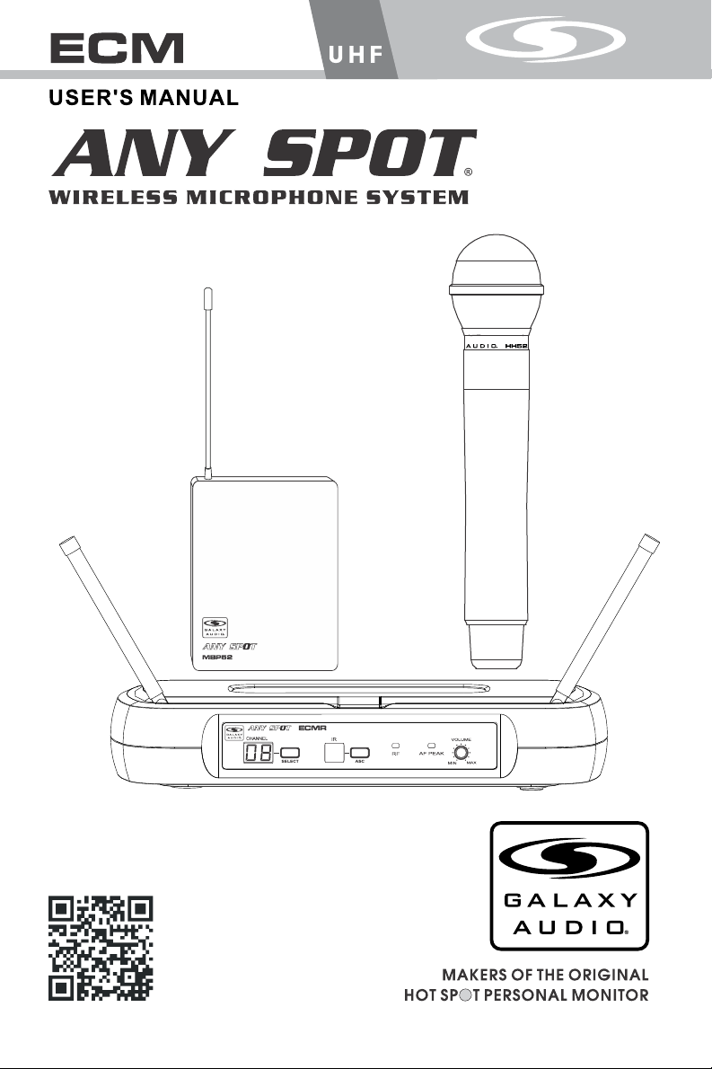
System Components
System Components
CHANNEL
IR
ASC SELECT
ECMR
VOLUME
AF PEAK
R F
MAX
MIN
All ECMR systems include the following components:
ECMR Receiver
One ¼" Audio Cable
Power Adapter
User Manual
Handheld Microphone Systems include the following:
HH52 Handheld Transmitter
Lavalier/Headset Microphone systems include the
following:
MBP52 Bodypack Transmitter
Microphone (choice of Lavalier, or Headset)
AS-HS
AS-LV
MBP52
1
Page 3
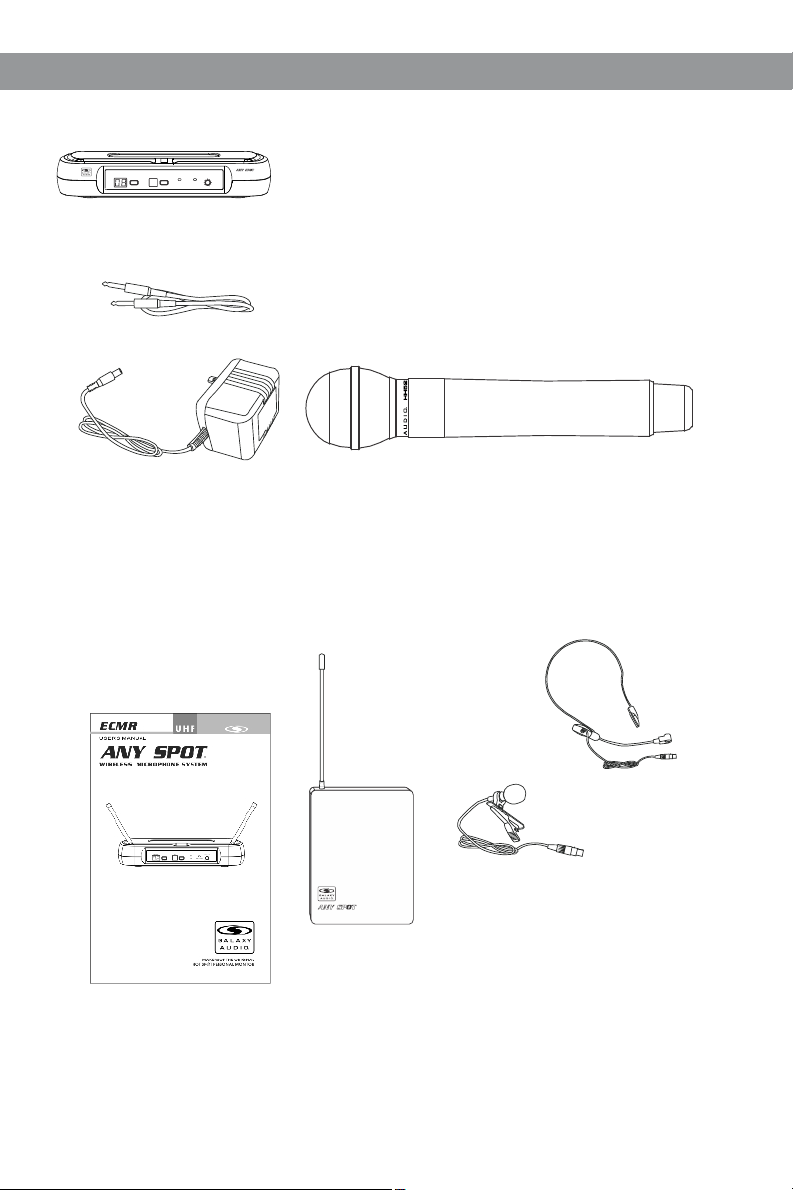
Front Panel
Functions of the ECMR Receiver
Functions of the ECMR Receiver
CHANNEL
1 2 3 4 5 6 7
1
Channel Display.
Displays selected Channel.
2
Channel select button
3
IR Window.
Unit sends Infrared Signal to the Transmitter
through this Window for Frequency
Synchronization.
4
ASC Synchronizing Signal Transmit Button.
Press this Button to establish Infrared connection
between the Receiver and Transmitter.
Rear Panel
AF OUTPU T
XLR BALA NCED -2 0dBV
IR
R F
ASC SELECT
5
RF Sign al LED
6
Audio L ED. Ind icate s a peak
AF PEAK
VOLUME
MAX
MIN
Audio Si gnal.
7
Audio O utput L evel Co ntrol .
Left tu rn for Ou tput Le vel Dec rease ,
right t urn fo r Outpu t Level I ncrea se.
D.C.12 -18V IN
400mA
2 IN 1 MIX
+
MUTE LEV EL
UNBAL OUT PUT
1 2 3 4
1
AF Audio Output.
2
Power Adapter Jack.
3
AF Output fine adjustment of Mute Threshold Level.
This is factory set and usually does not need to be adjusted.
If interference signals are present, this Threshold Value
can be Increased by turning the knob Clockwise until RF Signal LED goes out.
4
¼" Audio Output.
2
Page 4

HH52/HH52SC Handheld Transmitter
HH52/HH52SC Handheld Transmitter
Functions:
1
Microphone Head.
1
2
3
2
Gain (Sensitivity) Control.
Turn Left to Decrease Sensitivity.
Turn Right to Increase Sensitivity.
3
RF Power Level Switch.
H for High Level RF Power.
L for Low Level RF Power.
4
IR Window.
Receives Infrared signal to synchronize frequencies
between Receiver and Transmitter.
5
Battery Tray.
6
Power/ASC/Low Battery Indicator.
Green: Power On.
Flashing Green: IR Transmission in progress.
Red: Batteries Low.
7
Power On/Off Switch.
Changing Batteries:
4
5
Unscrew cover to access the Battery Tray. Observe
correct polarity markings when installing Batteries.
Expected life for two alkaline batteries is about 8 hours.
6
7
3
Page 5

MBP52 Bodypack Transmitter
MBP52 Bodypack Transmitter
Functions:
1
Antenna.
2
1
5
6
7
2
POWER
ASC
-
+
+
-
4
3
ASC SYSTEM
IR
n
o
i
t
ec
l
e
cy s
en
u
q
e
r
o f
Aut
p
etu
r s
te
t
mi
s
ran
o t
t
Au
Input Gain Switch.
There are three Gain settings. Select the
setting most suitable to your application.
Mic.: Microphone Level.
0: Guitar Level.
-10dB: Line Level.
3
Power/Low Battery/IR Transmission LED.
Green: Power On, Batteries OK.
Flashing Red: Low Batteries.
Flashing Green: IR transmission in Progress.
4
3-pin Input Jack.
5
Power Button.
Press and Hold to switch Power On/Off.
6
ASC Automatic Frequency Synchronisation.
Press this button to establish Infrared
connection between the Transmitter and Receiver.
7
IR Window.
This window receives the Infrared signal during ASC.
2
How to Wear the MBP52 Transmitter:
Slide the transmitter clip onto the belt , or run a guitar strap
1
- -
++
+ +
--
through the transmitter clip , as shown in the diagram at left.
2
1
Open
Close
Battery Replacement:
Slide open the Battery Door as shown. Install Batteries
while observing correct polarity markings.
The life expectancy of two alkaline batteries is about 8 hours.
4
Page 6

System Setup
System Setup
ECMR Receiver Setup:
Channel Selection
Press channel Selector button to select desired Channel. When
switching Channels, wait for the Channel number display to stop
blinking before using the ASC function. For best results when
operating multiple systems, set every channel to achieve the
maximum distance between channels.
Receiver Volume Control:
Turn Left for Output Level decrease, turn Right for Output Level
increase.
Mute Level Threshold Adjustment:
The Mute Level is factory set and normally needs no adjustment.
However, you may turn clockwise if interference is present.
Automatic Transmitter Setup (ASC):
Remove the access cover on the Handheld Transmitter. Point the
IR Window of the Handheld towards the IR Window on the
Receiver and press the ASC button.
Start by pressing the ASC button on the MBP52 transmitter belt
pack. The LED on top will flash green for 15 seconds.
While it’s flashing, Point the IR window of the MBP52 belt pack
towards the IR window on the Receiver, and press the ASC
button on the ECMR receiver. If you have successfully synced
them, The orange RF LED on the ECMR receiver will turn on
indicating a signal from the transmitter.
Note: when establishing infrared connection between the receiver and
the transmitter, the distance between them should not exceed O.5m.
When more than one system are used, only IR window of one
transmitter should be pointed to the receiver for each infrared
connection.
5
Page 7

Specifications
Specifications
ECM System
Available Channels: 16
Frequency Range: CODE D 584 - 607 MHz
CODE L 655 - 679 MHz
Transmitter Output level: 10 dBm
Band: UHF
Operating Range Under Typical Conditions: 150' (50m)
Note: actual range depends on RF signal
absorption, reflection, and interference.
Audio Frequency Response: (+/-3dB) 60Hz~16KHz
Total Harmonic Distortion (+/-30KHz deviation,
1KHz tone): <1%
Dynamic Range: >90dB A-weighted
Operating Temperature Range:
14ºF to 122ºF (-10º C to +50º C)
Note: battery characteristics may limit
this range:
Bodypack Transmitter:
MBP52
Audio Input Level: 0 dBV to +10dBV
Gain Adjustment Range: mic/0/-10
Input Impedance: 5KΩ
Dimensions: 3.3" x 2.6" x 1"
(85mm H x 65mm W x 24mm D)
Weight: 3.0oz (85 g) (without batteries)
Power Requirements: 2 alkaline AA Batteries
or rechargeable batteries
Battery Life: About 8 hours
Handheld Transmitter: HH52
Max Audio input level: 0dBV
Gain (Sensitivity): Control High/Low RF power switch.
Dimensions: 9.8" x 2.1" dia. (250mm x 53mm dia.)
Weight: 9.5oz (270 g) (without batteries)
Power Requirements: 2 “AA”size alkaline or
rechargeable batteries
Battery Life: About 8 hours
Receiver: ECMR
Audio Output Level: (+/-30KHz deviation, 1KHz tone)
XLR connector (into 600Ω load) -12dBV
¼" connector (into 3KΩ load) -18dBV
Output Impedance: XLR connector 200Ω
¼" connector 1KΩ
XLR output: Impedance balanced
Pin1:Ground (cable shield)
Pin2:Audio
Pin3:No Audio
Sensitivity: -93dBm for 30dB
Image Rejection: >90dB
Dimensions: 1.75" x 9.25" x 121"
(44.45mm H x 235mm W x 121mm D)
Weight: 0.85lbs (.39kg)
Power Requirements: 13.5 V dc at 300mA, supplied
by external power supply.
EC M D CO DE
1 584.400
2 587.500
3 589.575
4 591.050
5 593.425
6 595.200
7 598.450
8 599.650
9 601.275
10 60 3. 775
11 60 5. 500
12 60 6. 750
13 58 6. 025
14 59 0. 525
15 59 4. 150
16 60 2. 450
EC M L CO DE
1 65 5. 200
2 65 6. 675
3 65 8. 500
4 66 0. 050
5 66 1. 500
6 66 2. 900
7 66 4. 425
8 66 6. 500
9 66 7. 800
10 66 9. 22 5
11 67 0. 80 0
12 67 2. 27 5
13 67 3. 72 5
14 67 5. 07 5
15 67 6. 50 0
16 67 8. 60 0
6
Page 8

 Loading...