

Page 1
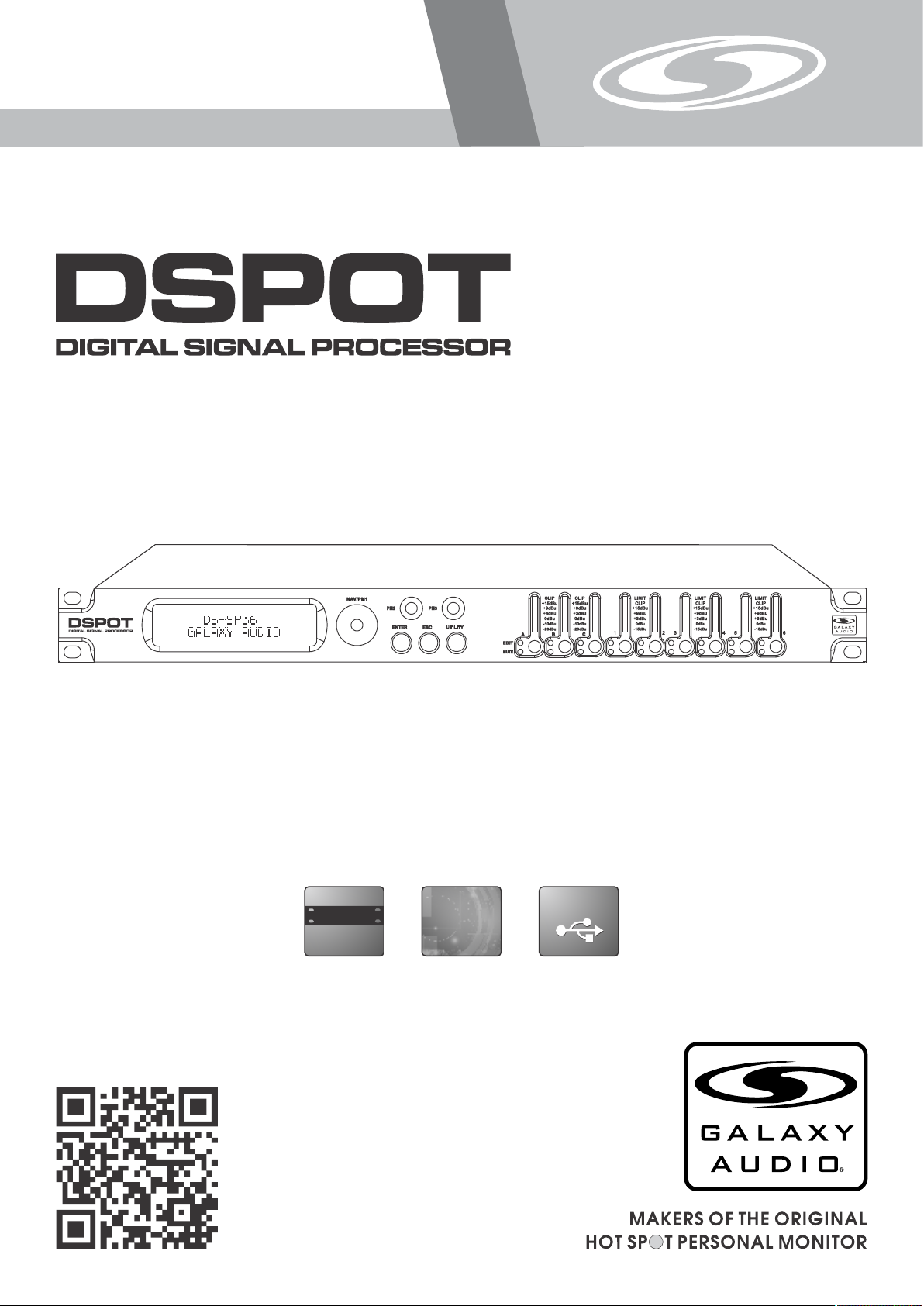
DS-SP36
USER’S MANUAL
DS-S P36
®
3x6 Speaker Processor
USB
19"
(482mm )
DIGITAL
DIGITAL
USB
Page 2

Contents
Contents
Introduction..........................................................................................1
Safety Instructions................................................................................ 2
Overview...............................................................................................3
Getting Started with Front Panel Controls........................................ 4 - 28
Using the PC Interface.................................................................. 29 - 34
Volume Controls Table................................................................. 35 & 36
Specifications..................................................................................... 37
Introduction
Introduction
Thank you for choosing a Galaxy DSPOT Digital Signal Processor. You have joined
hundreds of thousands of other satisfied Galaxy customers. Since 1977 Galaxy Audio’s
professional experience in design and manufacturing ensure our products' quality,
performance and reliability.
For the most up to date manual and information
visit www.galaxyaudio.com.
1
Page 3
Safety Instructions
Safety Instructions
This symbol indicates that dangerous voltage
Constituting a risk of electric shock is present
within this unit.
READ these instructions.
1.
KEEP these instructions.
2.
HEED all warnings.
3.
FOLLOW all instructions.
4.
DO NOT use this apparatus near water.
5.
CLEAN ONLY with dry cloth.
6.
DO NOT block any ventilation openings. Install in accordance with the manu-
7.
facturer's instructions.
DO NOT install near any heat sources such as radiators, heat registers, stoves,
8.
or other apparatus (including amplifiers) that produce heat.
DO NOT defeat the safety purpose of the polarized or grounding-type plug. A
9.
polarized plug has two blades with one wider than the other. A grounding type
plug has two blades and a third grounding prong. The wider blade or the third
prong are provided for your safety. If the provided plug does not fit into your
outlet, consult an electrician for replacement of the obsolete outlet.
PROTECT the power cord from being walked on or pinched, particularly at plugs,
10.
convenience receptacles, and the point where they exit from the apparatus.
ONLY USE attachments/accessories specified by the manufacturer.
11.
IMPORTANT SAFETY INSTRUCTIONS !
!
This symbol indicates that there are important
Operating and maintenance instructions in the
Literature Accompanying This Unit
12.
UNPLUG this apparatus during lightning storms or when unused for long periods of
13.
time.
REFER all servicing to qualified service personnel. Servicing is required when the
14.
apparatus has been damaged in any way, such as power-supply cord or plug is damAged, liquid has been spilled or objects have fallen into the apparatus, the apparatus
has been exposed to rain or moisture, does not operate normally, or has been
dropped.
DO NOT expose the apparatus to dripping and splashing. DO NOT put objects filled
15.
with liquids, such as vases, on the apparatus.
16.
Remove the batteries from the receiver if the system will not be used for a long
period of time. This will avoid any damage resulting from a defective, leaking
battery.
17.
DO NOT throw used batteries into a fire. Be sure to dispose of or recycle used
batteries in accordance with local waste disposal laws.
USE only with a cart, stand, tripod, bracket, or table
Specified by the manufacturer, or sold with the
Apparatus. When a cart is used, use caution when
moving the cart/apparatus combination to avoid
injury from tip-over.
2
Page 4

Overview
Described below are the functions of the front control buttons and encoders for the DS-SP36.
DS-S P36
1 2
1 - LCD Display
2 - Navigation/Parameter 1 Key
3 - Parameter 2 Key
4 - Enter Key
5 - Escape Key
6 - Utility Key
7 - Parameter 3 Key
8 - Input A Edit/Mute Button
®
5
3
4
6 7 8 9 10 16
11 12
13
14
15
9 - Input B Edit/Mute Button
10 - Input C Edit/Mute Button
11 - Output 1 Edit/Mute Button
12 - Output 2 Edit/Mute Button
13 - Output 3 Edit/Mute Button
14 - Output 4 Edit/Mute Button
15 - Output 5 Edit/Mute Button
16 - Output 6 Edit/Mute Button
3
Page 5
Getting Started Using Front Panel Interface
•
Getting Started
When the DS-SP36 is turned ON the device model name will appear in the LCD screen:
DS-SP36
GALAXY AUDIO
A status bar will show the progress of the DS-SP36 initialization process:
DS-SP36
The DS-SP36 has four factory pre-set working modes: “2x2 WAY + SUB”, “2x3 WAY..XOVER”, “6 WAY..
XOVER and “3x2 WAY..XOVER”.
After the initialization, the DS-SP36 will show on the LCD the first of the embedded preset working modes,
or the last one selected prior to the unit being turned off.
First time activation will default to the first of the preset working modes.
DS-SP36
2x2 WAY X-OVER
4
Page 6

• Encoders and ENTER, ESC buttons
The DS-SP36 is equipped with 3 Relative Encoders, “NAV/PM1”, “PM2” and “PM3”. These encoders allow
you to navigate the user interface and edit sections of the processor. They allow the user to navigate within
the screen for the selection of sub-menus, pages and parameters and to select the values to be assigned
during the editing operations.
The “ENTER” and “ESC” buttons allow the user to confirm or NOT confirm the operations performed by the
encoders.
• UTILITY, A/B/C and 1/2/3/4/5/6 buttons
The UTILITY button allows the User to enter the Sub-menus and set the general characteristics of the
Processor. The A, B and C buttons allow the User to enter the Editing Menus of the Processor's Input
Channels and buttons 1, 2, 3, 4, 5 and 6, allow the User to enter the Editing Menus of the Processor's
Output Channels.
The A, B and C buttons as well as the 1, 2, 3, 4, 5 and 6 buttons have double functions dependent on the
push and hold time.
When the A, B and C buttons are pushed and held for more than one second Input Channels A, B or C are
either muted or unmuted. The red LED will illuminate when the Channel is MUTED. When the “MUTE” LED
is OFF, then the related Input Channel is UN-MUTED.
A momentary push of the A, B and C buttons enters the Editing Mode for the Input Channels (see later for
the Input Channel Editing details). The blue “EDIT” LED will now be ON.
When the 1, 2, 3, 4, 5 and 6 buttons are pushed and held for more than one second the Output Channels 1,
2, 3, 4, 5 and 6 are either muted or unmuted. The red LED will illuminate when the Channel is muted. When
the “MUTE” LED is OFF, then the related Output Channel is UN-MUTED.
A momentary push of the 1, 2, 3, 4, 5 and 6 buttons enters the Editing Menu for the Output Channels (see
later for the Output Channel Editing details). The blue “EDIT” LED will now be ON.
• DS-SP36 Menu and Sub-Menu Structures
As stated above, the start-up default screen is the following factory preset:
DS-SP36
2x2 WAY X-OVER
From this point, sub-menus are accessed using the UTILITY”, “A/B/C”, “1/2/3/4/5/6”, “ENTER” And “ESC”
buttons and all parameters and values are navigated by the “NAV/PM1”, “PM2” and “PM3” encoders.
Please refer to the following menu structures:
5
Page 7

● Menu “UTILITY” [access by pushing the “UTILITY” button]
From the “Default Screen”, it is possible access the “UTILITY” menu by pushing the “UTILITY” button and
the Sub-Menus pages can be selected by rotating the “NAV/PM1” encoder clockwise and
Counter-clockwise.
Once selecting the sub-menu page, using the “ENTER” button, you can access the Sub-Menu pages.
Again “scrollable” using the “NAV/PM1” encoder and accessible for editing parameters by again pushing
the “ENTER” button. Through the “ESC” button, it is possible at any time, to back through the pages.
Once inside the Sub-Menus pages, several options can be scrolled through using the PM2 or PM3
encoders, and selected/confirmed by pushing the “ENTER” button.
Note: In every Sub-Menu, the option currently selected/running will have an asterisk “ * ” showing to the
right of the description on the LCD screen.
Options that are not selected/running will be displayed without an asterisk.
Pushing the ENTER button, on an unselected option, will mean an asterisk will then appear and this
option will now take over as the currently selected/running option.
System Utilities Sub-menu – this sub-menu allows you to access several operations related to the
DS-SP36 Start Up and General Configuration:
UTILITY MENU
– System Utilities --
From the “System Utilities Sub-menu”, pushing “ENTER” and then using the “NAV/PM1” encoder for
scrolling will give access to the following pages:
– System Setup: this page allows the selection of the operating mode of the DS-SP36:
SYSTEM UTILITY
– System Setup –
The operating mode can be chosen from a selection of 4 Xover options
2x2 WAY + SUB ........... in this operating mode, the DS-SP36 is configured as a 2 Input to 4 Output X-Over,
plus the third Input as SUB, where the 3 Inputs are automatically assigned to the Output as follows:
– Input A to Outputs 1 and 3 [Out1=Low-A and Out3=High-A]
– Input B to Outputs 2 and 4 [Out2=Low-B and Out4=High-B]
– Input C to Outputs 5and 6 [Out5=Sub-A and Out6=Sub-B]
2x3 WAY ..XOVER......... in this operating mode, the DS-SP36 is configured as a 2 Input to 6 Output
X-Over (the Input C is not used), where the 2 Inputs are automatically assigned to the Outputs as follows:
– Input A to Outputs 1,3 and 5 [Out1=Low-A , Out3=Mid-A and Out5=High-A]
– Input B to Outputs 2,4 and 6 [Out2=Low-B , Out4=Mid-B and Out6=High-B]
6
Page 8

6 WAY ..XOVER...... . in this operating mode, the DS-SP36 is configured as a Mono Input to 6 Output
X-Over, where the Input A is automatically assigned to the Outputs as follow:
– Input A to Outputs 1,2,3,4,5 and 6 [Out1=Near-1, Out2=Near-2, Out3=Mid-1 and Out4=Mid-2, Out5=Far1, Out6=Far-2]
3x2 WAY ..XOVER..... . in this operating mode, the DS-SP36 is configured as a 3 Input to 6 Output X-Over,
where the Inputs are automatically assigned to the Outputs as follow:
– Input A to Outputs 1 and 2 [Out1=Low-A and Out2=High-A]
– Input B to Outputs 3 and 4 [Out3=Low-B and Out4=High-B]
– Input C to Outputs 5 and 6 [Out5=Low-C and Out6=High-C]
By pressing ENTER on the System Setup page and rotating the “PM2” or “PM3” encoder, it is possible to
select all the available X-Over preset modes.
When the “2x3 WAY XOVER” is selected, the “System Setup” page will appear as follows:
System Setup
Setup: 2x3 WAY XOVER
To change the desired operating mode for the DS-SP36, the screen must reflect the X-Over required and
then simply pressing the “ENTER” button will bring up the following screen asking for confirmation to load
the selected operating mode:
New Xover
[ENTER] to confirm
If confirmed by pressing ENTER, the selected preset mode will load. While the device is configuring the
X-over the following screen will be appear:
Please Wait.....
Changing Xover
The new preset mode will now be shown with an asterisk.
– Input Routing: the DS-SP36 Processor is equipped with 3 Analog Inputs (Balanced Female XLR) and a
stereo S/PDIF Digital Input (RCA connector).
The “Routing Options” page allows you to select the desired Input type:
SYSTEM UTILITY
– Input Routing –
7
Page 9
By pressing ENTER on Input Routing, and then rotating the “PM2” or “PM3” encoders, it is possible to
select the main Inputs for the DS-SP36, allowing the User to choose between Analog or S/PDIF Digital.
The selection can be confirmed by pressing the “ENTER” button. The following screen shows that the
Analog Input has been selected:
Input Routing
Source: Analog
– Power-On Procedure: this gives you the ability to select the option that will apply when the DS-SP36
powers up after being switched on.
– Delay Time/Distance: this page allows you to select the measurement unit to be used for the Delays:
Time (in milliseconds “ms”) or Distance (in meters “m”:)
SYSTEM UTILITY
– Delay Units –
By pressing ENTER and rotating the “PM2” or “PM3” encoder, it is possible to select the measurement unit
to be used for the delay, which will be confirmed by pushing the ENTER button.
The following screen shows the selected delay measurement is Time (milliseconds):
Delay Units
Unit: Time (ms)
– Software Version:
This page allows you to confirm the Software Version running on the DS-SP36:
SYSTEM UTILITY
– Software Version –
8
Page 10
Program Utilities Sub-menu – this sub-menu allows you to access several options related to the
DS-SP36 operating mode and to manage the presets stored and recallable within the Unit:
UTILITY MENU
– Program Utilities –
By pressing the ENTER button and then using the “NAV/PM1” encoder the following pages can be
accessed:
– Recall a Program: this page allows the Loading of a preset program. You can store up to 24 presets in
the DS-SP36 memory:
PROGRAM UTILITY
– Recall a Program –
By pressing ENTER and rotating the “PM2”or “PM3” encoders, it is possible to scroll through all current
available user presets.
If NO USER PRESETS are stored yet, the screen will show the following:
Recall a Program
No Stored Xovers
If presets have previously been stored by the user, anyone of them can be recalled:
[ENTER] to Recall
01: PRESET 1
By using the “PM2” or “PM3” encoder it is possible to scroll through the stored presets. Once the desired
preset appears on the screen select it by pressing the “ENTER” button and this will force the DS-SP36 to
begin to load this selected preset and the following transition screen will appear:
Loading New Program
01: PRESET 1
Once loaded the DS-SP36 will exit to the “Recall a Program” screen automatically and the above screen
will disappear:
PROGRAM UTILITY
– Recall a Program –
Note: At any time it is possible to quit the recall action by pressing the “ESC” button.
9
Page 11
– Save a Program: this page allows you to store a new preset in the DS-SP36’s memory:
PROGRAM UTILITY
– Save a Program –
By pressing the ENTER button and rotating the “PM2” or “PM3 encoder, it is possible to scroll through the
previously saved presets and the available empty locations (identified by “Empty Memory”).
If no user presets are stored, the “Save a Program” screen will show empty memory locations for all 1-24
presets as shown in the example below for location 10:
Save a Program
10: Empty Memory
When storing an edited configuration for the DS-SP36, select the location for a preset from the 24 available
by using the “PM2” or “PM3” encoders.
Once the desired location appears on the screen press ENTER again to reach the “Set Program Name”
page.
In this page the User can enter a Preset Name ( up to 16 Characters ) by using the “PM2” or “PM3”
encoder to choose a character and the “NAV/PM1” encoder to move between the 16 available locations for
the character’s positioning.
The current position of the cursor is shown by a “blinking underscore”.
The following is an example of a screen while entering the preset name “Stage 1 2x2” in location 10:
Set Program Name
10: Stage 1 2x2 ?
To store the Preset Name press the “ENTER” button again.
The above action will take you to the “Enter to Save” page showing the selected location for
the preset and the final edited name:
[Enter] to Save
10: Stage 1 2x2 ?
Pressing “ENTER” again, will store the preset in the selected location with the chosen name and the
following transition screen will appear on the LCD:
Saving to Memory
10: Stage 1 2x2
10
Page 12
Once the preset is stored, the above screen will disappear returning to the following screen:
PROGRAM UTILITY
– Save a Program –
If during the Preset Storing process you want to overwrite an existing memory location, select the desired
location in the “Save a Program” page, then ENTER and you will be asked if you want to overwrite this
preset with the following “[ENTER] to Overwrite” screen displaying the currently stored preset and location:
[Enter] to Overwrite
10: Stage 1 2x2 ?
If you wish to proceed, press “ENTER” again and the DS-SP36 will proceed with the “Set Program Name”
page and the subsequent overwrite on completion of the previously described storing process.
Note: At any time it is possible to quit the storing action by pressing the “ESC” button.
– Delete a Program: this page allows you to delete a preset already stored in the DS-SP36 memory:
PROGRAM UTILITY
– Delete a Program –
By pressing the ENTER button and rotating the “PM2” or “PM3” encoder, it is possible to scroll through the
previously saved presets and the available empty locations (identified by “Empty Memory”).
If no user presets are stored, the “Delete a Program” screen will show empty memory locations for all 1-24
presets as shown in the example below for location 10:
Delete a Program
10: Empty Memory
If Presets are available they will be shown in the “Delete a Program” page as follows:
Delete a Program
10: Stage 1 2x2
By using the “PM2” or “PM3” encoder it is possible to select a preset to be deleted.
Pressing the “ENTER” button on a selected preset will bring up the “[Enter] to Delete” page, showing the
selected preset.
11
Page 13

For example, if we want to delete the preset 10, “Stage 1 2x2”, the screen will show the following:
[Enter] to Delete
10: Stage 1 2x2
Confirm the deletion by pressing “ENTER” again. This will force the DS-SP36 to erase the selected preset
and the following transition screen will appear:
Erasing Xover Memory.....
10: Stage 1 2x2
Once the preset is deleted, the above screen will disappear, returning to the following screen:
PROGRAM UTILITY
– Delete a Program –
Note: At any time it is possible to quit the deleting action by pressing the “ESC” button.
Interface Utilities Sub-menu – this sub-menu allows you to define the remote control interface
[USB or RS485] to be used for controlling the DS-SP36 :
UTILITY MENU
– Interface Utilities –
From “Interface Utilities”, press “ENTER” to access the Interface Setup.
– Interface Setup: this screen allows you to choose the remote control protocol for the DS-SP36.
INTERFACE UTILITY
– Interface Setup –
By pressing “ENTER” and then using the PM2 or PM3 encoders you can choose between the two possible
interfaces (USB or RS485 ) for the DS-SP36.
Pressing ENTER on a selected source will make an asterisk appear to the right of the description on the
LCD, as in the following example which shows the selected interface as USB.
Interface Setup
Source: USB
12
Page 14

Security Sub-menu – this sub-menu allows the User to set the parameters shown, lock the DS-SP36 and
set a Password, therefore limiting the unit's functions and controls to those who have access to the
appropriate Password.
UTILITY MENU
– Security Utilities –
Press ENTER and then use the NAV/PM1 to scroll between options.
– Show Parameter: Pressing ENTER from the above menu will access the “Show Parameter” Sub Menu
SECURITY UTILITY
– Show Parameter –
Press ENTER again and use the PM2 or PM3 encoders to scroll between the “be shown” and “not be
shown” options. An asterisk will highlight which option is selected.
Choosing the “be shown” option means that once the unit is locked, you cannot access parameter editing
features, but they will be displayed on the LCD screen.
Choosing the “not be shown” option means that once the unit is locked, the parameters will not be shown at
all. With this option, when trying to access a parameter, the following screen message will appear:
Parameter will
not be shown
– Lock Unit: this sub-menu allows the user to lock the device so no parameters can be edited or modified.
SECURITY UTILITY
– Lock Unit –
When the Unit is in an unlocked condition, all parameters will be available for editing. When you select On,
all parameters will be locked and are not available for editing.
Lock Unit
Lock: On
When you select lock from the menu, the unit will be locked and the lock menu automatically exited. The
screen will revert to the “Default”, showing the current XOVER configuration and the preset selected, and
beside the preset’s name, a “keylock” icon indicating that the DS-SP36 is locked.
13
Page 15

– User Password: from the “User Password” sub-menu:
SECURITY UTILITY
– User Password –
Press “ENTER” to access the “User Password” page:
User Password
[ ]
Using the PM2 or PM3 encoders to choose a character and the “NAV/PM1” encoder to move between
available locations, you can enter a 6 Character Password Name.
The current position of the cursor for the characters to be entered is shown by a “blinking underscore”.
During this editing phase, the display is as follows if we were using “DSSP36” as the password:
User Password
[ DSSP36 ]
The DS-SP36 will exit the “Unit Lock” sub-menu and jump to the “User Password” sub-menu page screen:
SECURITY UTILITY
– Insert Password –
If the password entered in the “Confirm Password” page matches the one entered in the “Enter Password”
page, the following screen will appear:
Confirm Password
[ DSSP36 ]
The Password is now configured and held in the device’s memory.
The user can now decide to “lock” the DS-SP36 by Password, inhibiting the access to ALL processor
functions depending on the setting of the parameter “Password Enable/Disable”, explained in the following
paragraph.
14
Page 16

– Enable Password: from the “Enable Password” sub-menu:
SECURITY UTILITY
– User Password –
Press “ENTER” to gain access to the “Enable Password” screen:
Enable Password
Password: Disable
Once a Password has been entered into the DS-SP36 through the steps described in the previous section,
it is possible to “Enable” or “Disable” the password function and therefore lock the DS-SP36 restricting
access to all functions.
When a password has been entered you will be able to select the “Enable” option from the menu and the
unit will not be accessible for editing. In “Locked by Password Status”, all DS-SP36 functions are
inhibited to the User, including the use of the Mute A/B/C and MUTE 1/2/3/4/5/6 buttons.
The only access available is to the parameters of the input/output channels (accessible by pressing the edit
button), ONLY to READ the values (no editing possible) if the “be shown” flag in the “Show Parameter”
Sub-Menu has been selected.
Once “Locked by Password”, the “keylock” icon will appear on the default LCD screen and no menu pages
will be accessible, with the exception of the “User Password” option.
To regain access to the full operation of the DS-SP36, ENTER to the “User Password” screen and press
the UTILITY Button to access the following screen to enable the correct password to be entered:
User Password
[ ]
After the correct password has been entered, you will be able to access the full functionality of the
DS-SP36. The “lock Icon” will disappear from the “Default Screen”and automatically the “Enable Password”
page will be back to the “Disable” condition:
Enable Password
Password: Disable
If no Password has been set within the DS-SP36, as described in the previous paragraphs, the DS-SP36
will not allow you to enable any Password, and the choice in the “Enable Password” will be limited to only
the “Disable” option.
15
Page 17

● Menu “Input A/B/C” Input Channels Editing [access by pushing the “A/B/C”
buttons]
From the “Default Screen”, it is possible to access the “Input A/B/C” menu by pushing the “A” or “B” or “C”
button. Once the button is pressed, the related blue “EDIT” LED will turn ON. The Sub-Menu pages can
now be scrolled through by rotating clockwise and counter-clockwise the “NAV/PM1” encoder.
For parameter editing it is necessary to press ENTER and an arrow will appear on the left of the screen
“ -> ”. Then use the “PM2” and “PM3” encoders for selecting and setting the parameter values. On some
parameters that have three independent values, you will also need to use the PM1 encoder, eg filter
parameter settings.
Note: All parameter editing can be done using the “NAV/PM1”, “PM2”, and “PM3” encoders and the current
shown value of the selected option is AUTOMATICALLY loaded during the encoders’ use and stored as the
current value once leaving the page is AUTOMATICALLY loaded during the encoders' use and stored as
current value once the page is left.
Gain page – from this screen it is possible to set the Input Channels Level from -12dB to +6dB. Press
ENTER, and an arrow will appear on the left of the screen “ -> ” then use the “PM1” or “PM2” buttons.
The value set on this screen will only affect the input level of the selected Channel A, B or C.
The following is an example screen for the “Gain” page that has set the Gain of Input Channel A to +0.0dB:
Input-A Gain
–› Gain = + 0.0dB
Delay page – from this page it is possible to set the Input Channels Delay Time from 000.0000mS up to
848.9984mS, by steps of 1mS or 20.8uS.
To set the Delay time, press ENTER, and an arrow will appear on the left of the screen “ -> ”. Then use the
“PM2” encoder to set the Delay Time in steps of 1mS and the “PM3” for setting the “fine” Delay Time in
steps of 20.8 microseconds.
The following is an example screen for the “Delay” page where the Delay Time of Input Channel A is set to
160.1872mS:
Input-A Delay
–› Gain = 160.1872mS
16
Page 18

EQ: [x] sub-menu – from this sub-menu it is possible to set the Input Channels five available Parametric or
Shelving Filters.
Input-A EQ-X
1.00KHz BW1.05 0.0dB
The DS-SP36 allows the user to select either Bell or Shelving Parameters and assign them independently
using the 5 available filters.
In order to select the filter's type, it is necessary to have the filter's GAIN=0.0dB, then using the PM2
encoder, rotate it “clockwise” in order to select the Bell filter's Bandwidth, or “counter-clockwise” to select
the Shelving filter type (Low or High) and its order (1st or 2nd).
So, in order to define the filter type for the filter number 1 (“x”=1), it is necessary from the above screen, to
enter the filter's editing page pressing the ENTER button, and the screen will appear as follows:
Input-A EQ-1
–› 1.00KHz BW1.05 0.0dB
In this case, the filter's GAIN=0.0dB, and BW=1.05, the current filter selected is a Bell type now, rotating the
PM2 encoder clockwise, the parameter BW will range from 0.05 up to 3 for identifying a bandwidth value for
a Bell filter.
If a Bell filter is selected, then the Gain can be modified from 0.0dB and the BW will range between 0.05
and 3.
If the user wants to select a Shelving filter from the above setting, with the GAIN=0.0dB (if the GAIN is not
0.0dB, it is necessary to set it at 0.0dB using the PM3 encoder), rotate the PM2 Counter-clockwise. Once
BW reaches the 0.05 value, with the next step of the PM2 counter-clockwise rotation, the selection of the
Shelving filters will be entered.
Still rotating the PM2 counter-clockwise, the Shelving filters and their order will be selectable in the
following sequence:
1. 1st order Low Shelving = -6LoSh [on the screen]
2. 2nd order Low Shelving = -12LoSh [on the screen]
3. 1st order High Shelving = -6HiSh [on the screen]
4. 2nd order High Shelving = -12HiSh [on the screen]
Once the desired Shelving filter is selected, the PM3 can then be used to select the desired GAIN and
when the GAIN is set at a value different from 0.0dB, then the filter type cannot be changed until this GAIN
is returned to 0.0dB.
17
Page 19

BELL Filter: As an example, if we want to set a bell filter within EQ-1, then the BW has to be set at a
desired value of say 1.00 using the PM2 encoder, the GAIN at say +3dB using the PM3 encoder and the
Center Frequency at say 1.00KHz with the NAV/PM1 encoder.
The EQ sub-menu screen will show the following:
Input-A EQ-1
–› 1.00KHz BW=1.00 + 3.0dB
Once in the Bell Filter's edit screen all the filter's parameters can be modified using the “NAV/PM1”, “PM2”
and “PM3” encoders for editing the Filter's Center Frequency, Bandwidth BW and Gain.
The Center Frequency of the Parametric Filter can be edited using the “NAV/PM1” encoder, the BW the
“PM2” encoder and the Gain the “PM3” encoder:
“Center Frequency”: the selectable frequencies range is from 20Hz to 20kHz in steps of 1/24 of an Octave
and can be adjusted by rotating the “NAV/PM1” encoder.
“Bandwidth BW”: the selectable BW range is from 0.05 Octave to 3 Octave in steps of 0.05 Octave and
can be adjusted by rotating the “PM2” encoder.
“Gain”: the selectable Gain range is from -15dB to +15dB in steps of 0.5 dB and can be adjusted by
rotating the “PM3” encoder.
Low Shelving Filter: As an example, if we want to set a low shelving filter within EQ-1, then the PM2
encoder has to be rotated counter-clockwise until the desired Low Shelving filter, say -6LoSh appears on
the screen, the GAIN at say +3.0dB using the PM3 encoder and the High Cut Frequency at say 1.00KHz
with the NAV/PM1 encoder.
The EQ sub-menu screen will show the following
Input-A EQ-1
–› 1.00KHz -6LoSh + 3.0dB
Note: Once the desired Low Shelving filter is selected, the PM3 can then be used to select the desired
GAIN and when the GAIN is set at a value different from 0.0dB, then the filter type cannot be changed until
this GAIN is returned to 0.0dB.
Once in the Low Shelving Filter's edit screen all the filter's parameters can be modified using the
“NAV/PM1”, “PM2” and “PM3” encoders for editing the Filter's High Cut Frequency, Filter's Order and Gain.
The Hi Cut Frequency of the Low Shelving Filter can be edited using the “NAV/PM1” encoder, the Filter's
Order can be adjusted by the “PM2” encoder and the Gain the “PM3” encoder:
“Hi Cut Frequency”: the selectable frequencies range is from 20Hz to 20kHz in steps of 1/24 of an Octave
and can be adjusted by rotating the “NAV/PM1” encoder.
“Low Shelving Order”: the selectable Low Shelving Filter's range can be selected between the 1st
(Lo-1st.) and the 2nd (Lo-2nd.) one.
“Gain”: the selectable range of the Gain is from -15dB to +15dB in steps of 0.5 dB and can be adjusted by
rotating the “PM3” encoder.
18
Page 20

High Shelving Filter: As an example if we want to set a high shelving filter within EQ-1 then the PM2
encoder has to be rotated counter-clockwise until the desired High Shelving filter say -6HiSh appears on
the screen, the GAIN at say +3dB using the PM3 encoder and the Low Cut Frequency at say 1.00KHz with
the NAV/PM1 encoder.
The EQ sub-menu screen will show the following
Input-A EQ-1
–› 1.00KHz -6HiSh + 3.0dB
Note: Once the desired High Shelving filter is selected, the PM3 can then be used to select the desired
GAIN and when the GAIN is set at a value different from 0.0dB, then the filter type cannot be changed until
this GAIN is returned to 0.0dB.
Once in the High Shelving Filter's edit screen all the filter's parameters can be modified using the
“NAV/PM1”, “PM2” and “PM3” encoders for editing the Filter's Low Cut Frequency, Filter's Order and Gain.
The Lo Cut Frequency of the High Shelving Filter can be edited using the “NAV/PM1” encoder, the Filter's
Order can be adjusted by the “PM2” encoder and the Gain the “PM3” encoder:
“Lo Cut Frequency”: the selectable frequencies range is from 20Hz to 20kHz in steps of 1/24 of an Octave
and can be adjusted by rotating the “NAV/PM1” encoder.
“High Shelving Order”: the selectable High Shelving Filter's range can be selected between the
1st (Lo-1st.) and the 2nd (Lo-2nd.) one.
“Gain”: the selectable range of the Gain is from -15dB to +15dB in steps of 0.5 dB and can be adjusted by
rotating the “PM3” encoder.
Note1 : Once the desired options have been selected using the 3 encoders, they are automatically saved
as current and stored in the DS-SP36 system status once leaving the page.
Note2 : To exit this page, push the “ESC” button.
● Menu “Output 1/2/3/4/5/6” Output Channels Editing [access by pushing the
“1/2/3/4/5/6” buttons]
From the “Default Screen”, it is possible to access the “Output Channel” menu by pressing the “1” or “2”or
“3” or “4” or “5” or “6” button. Once pressed, the related blue “EDIT” LED will turn ON.
The Sub-Menus pages can now be scrolled through by rotating clockwise and counter-clockwise the
“NAV/PM1” encoder.
For parameter editing it is necessary to press ENTER and an arrow will appear on the left of the screen
“ -> ”. Then use the “PM2” and “PM3” encoders for selecting and setting the parameter values. On some
parameters that have three independent values, you will also need to use the PM1 encoder, for example for
the filter’s parameter setting.
Note: All parameter editing can be done using the “NAV/PM1”, “PM2”, and “PM3” encoders and the current
shown value of the selected option is AUTOMATICALLY loaded during the encoders’ use and stored as the
current value once leaving the page.
HPF sub-menu – from this sub-menu it is possible to set the Output Channels High Pass Filter (HPF).
The following is an example of a HPF sub-menu screen with the filter set at 24dB Linkwitz/Riley on
Output1... using the name “High” (see later for assigning a Name to the outputs):
19
Page 21

Out-1 High HPF
–› 20.0Hz Lnk/Ril 24dB
The filter's parameters can be modified by use the “PM2” and “PM3” encoders for editing the Filter's Low
Cut Frequency and the Filter's Type and Order.
The Low Cut Frequency of the High Pass Filter can be edited using the “PM2” encoder and the Filter's Type
and Order can be edited by using the “PM3” encoder.
“Low Cut Frequency”: the selectable frequencies range is from 20Hz to 20kHz in steps of 1/24 of an
Octave and can be adjusted by rotating the “PM2” encoder.
“High Pass Type and Order”: allows you to select the XOver's High Pass Filter Shape and Order.
The available shapes and orders for the High Pass Filter, that are accessible by rotating the “PM3” encoder,
are listed below:
– No Cut-Off (High Pass Filter Bypassed)
– Butwrth 6dB (Butterworth Filter 6dB/Oct Slope)
– Butwrth 12dB (Butterworth Filter 12dB/Oct Slope)
– Lnk/Ril 12dB (Linkwitz/Riley Filter 12dB/Oct Slope)
– Bessel 12dB (Bessel Filter 12dB/Oct Slope)
– Butwrth 18dB (Butterworth Filter 18dB/Oct Slope)
– Butwrth 24dB (Butterworth Filter 24dB/Oct Slope)
– Lnk/Ril 24dB (Linkwitz/Riley Filter 24dB/Oct Slope)
– Bessel 24dB (Bessel Filter 24dB/Oct Slope)
Note1 : Once the desired options have been selected using the 2 encoders, they are automatically saved
as current and stored in the DS-SP36 system status once leaving the page.
Note2 : To exit this page, push the “ESC” button.
LPF sub-menu – from this sub-menu it is possible to set the Output Channels Low Pass Filter (LPF).
The following is an example of a LPF sub-menu screen with the filter set at 24dB Linkwitz/Riley on
Output1... using the name “Low” (see later for assigning a Name to the outputs):
Out-1 Low LPF
–› 20.0Hz Lnk/Ril 24dB
The filter's parameters can be modified by use the “PM2” and “PM3” encoders for editing the Filter's High
Cut Frequency and the Filter's Type and Order.
The High Cut Frequency of the Low Pass Filter can be edited using the “PM2” encoder and the Filter's Type
and Order can be edited by using the “PM3” encoder.
20
Page 22

“High Cut Frequency”: the selectable frequencies range is from 20Hz to 20kHz in steps of 1/24 of an
Octave and can be adjusted by rotating the “PM2” encoder.
“Low Pass Type and Order”: this page allows you to select the XOver's Low Pass Filter Shape and Order.
The available shapes and orders for the Low Pass Filter that are accessible by rotating the “PM3” encoder
are listed below:
– No Cut-Off (Low Pass Filter Bypassed)
– Butwrth 6dB (Butterworth Filter 6dB/Oct Slope)
– Butwrth 12dB (Butterworth Filter 12dB/Oct Slope)
– Lnk/Ril 12dB (Linkwitz/Riley Filter 12dB/Oct Slope)
– Bessel 12dB (Bessel Filter 12dB/Oct Slope)
– Butwrth 18dB (Butterworth Filter 18dB/Oct Slope)
– Butwrth 24dB (Butterworth Filter 24dB/Oct Slope)
– Lnk/Ril 24dB (Linkwitz/Riley Filter 24dB/Oct Slope)
– Bessel 24dB (Bessel Filter 24dB/Oct Slope)
Note1: Once the desired options have been selected using the 2 encoders, they are automatically saved as
current and stored in the DS-SP36 system status once leaving the page.
Note2: To exit this page, push the “ESC” button.
EQ: [x] sub-menu – from this sub-menu, it is possible to set the Output Channels five available Parametric
or Shelving Filters.
Out-1 Name EQ-X
1.00KHz BW1.05 0.0dB
The DS-SP36 allows the user to select either Bell or Shelving Parameters and assign them independently
using the 5 available filters.
In order to select the filter's type, it is necessary to have the filter's GAIN=0.0dB, then using the PM2
encoder, rotate it “clockwise” in order to decide the Bell filter's Bandwidth, or “counter-clockwise” to select
the Shelving filter type (Low or High) and its order (1st or 2nd ).
So, in order to define the filter type for the filter number 1 (“x”=1), it is necessary from the above screen, to
enter the filter's editing page pressing the ENTER button, and the screen has to appear as follows:
Out-1 Name EQ-1
–› 1.00KHz BW1.05 0.0dB
21
Page 23

In this case, the filter's GAIN=0.0dB, and being BW=1.05, the current filter selected is a Bell type.
Now, rotating the PM2 encoder clockwise, the parameter BW will range from 0.05 up to 3 for identifying a
bandwidth value for a Bell filter.
If a Bell filter is selected, then the Gain can be modified from 0.0dB and the BW will range between 0.05
and 3.
If the user wants to select a Shelving filter from the above setting, with the GAIN=0.0dB [if the GAIN is not
0.0dB, it is necessary to set it at 0.0dB using the PM3 encoder], rotate the PM2 Counter-clockwise. Once
BW reaches the 0.05 value, at the next step of the PM2 counter-clockwise rotation, the selection of the
Shelving filters will be entered.
Still rotating the PM2 counter-clockwise, the Shelving filters and their order will be selectable in the
following sequence:
1. 1st order Low Shelving = -6LoSh [on the screen]
2. 2nd order Low Shelving = -12LoSh [on the screen]
3. 1st order High Shelving = -6HiSh [on the screen]
4. 2nd order High Shelving = -12HioSh [on the screen]
Once the desired Shelving filter is selected, the PM3 can then be used to select the desired GAIN and
when the GAIN is set at a value different from 0.0dB, then the filter type cannot be changed until this GAIN
is returned to 0.0dB.
BELL Filter: As an example, if we want to set a bell filter within EQ-1, then the BW has to be set at a
desired value of say 1.00 using the PM2 encoder, the GAIN at say +3dB using the PM3 encoder and the
center Frequency at say 1.00KHz with the NAV/PM1 encoder.
The EQ sub-menu screen will show the following
Out-1 Name EQ-1
–› 1.00KHz BW=1.00 3.0dB
Once in the Bell Filter's edit screen, all the filter's parameters can be modified using the “NAV/PM1”, “PM2”
and “PM3” encoders for editing the Filter's Center Frequency, Bandwidth BW and Gain.
The Center Frequency of the Parametric Filter can be edited using the “NAV/PM1” encoder, the BW the
“PM2” encoder and the Gain the “PM3” encoder:
“Center Frequency”: the selectable frequencies range is from 20Hz to 20kHz in steps of 1/24 of an Octave
and can be adjusted by rotating the “NAV/PM1” encoder.
“Bandwidth BW”: the selectable BW range is from 0.05 Octave to 3 Octave in steps of 0.05 Octave and
can be adjusted by rotating the “PM2” encoder.
“Gain”: the selectable Gain range is from -15dB to +15dB in steps of 0.5 dB and can be adjusted by
rotating the “PM3” encoder.
Low Shelving Filter: As an example, if we want to set a low shelving filter within EQ-1 then the PM2
encoder has to be rotated counter-clockwise until the desired Low Shelving filter say -6LoSh appears on
the screen, the GAIN at say +3.0dB using the PM3 encoder and the High Cut Frequency at say 1.00KHz
with the NAV/PM1 encoder.
The EQ sub-menu screen will show the following
Out-1 Name EQ-1
–› 1.00kHz -6LoSh + 3.0dB
22
Page 24

Note: Once the desired Low Shelving filter is selected, the PM3 can then be used to select the desired
GAIN and when the GAIN is set at a value different from 0.0dB, then the filter type cannot be changed until
this GAIN is returned to 0.0dB.
Once in the Low Shelving Filter's edit screen all the filter's parameters can be modified using the
“NAV/PM1”, “PM2” and “PM3” encoders for editing the Filter's High Cut Frequency, Filter's Order and Gain.
The Hi Cut Frequency of the Low Shelving Filter can be edited using the “NAV/PM1” encoder, the Filter's
Order can be adjusted by the “PM2” encoder and the Gain the “PM3” encoder:
“Hi Cut Frequency”: the selectable frequencies range is from 20Hz to 20kHz in steps of 1/24 of an Octave
and can be adjusted by rotating the “NAV/PM1” encoder.
“Low Shelving Order”: the selectable Low Shelving Filter's range can be selected between the 1st
(Lo-1st.) and the 2nd (Lo-2nd.) one.
“Gain”: the selectable range of the Gain is from -15dB to +15dB in steps of 0.5 dB and can be adjusted by
rotating the “PM3” encoder.
High Shelving Filter: As an example, if we want to set a high shelving filter within EQ-1 then the PM2
encoder has to be rotated counter-clockwise until the desired High Shelving filter, say -6HiSh, appears on
the screen, the GAIN at say +3dB using the PM3 encoder and the Low Cut Frequency at say 1.00KHz with
the NAV/PM1 encoder.
Out-1 Name EQ-1
–› 1.00kHz -6HiSh + 3.0dB
Note: Once the desired High Shelving filter is selected, the PM3 can then be used to select the desired
GAIN and when the GAIN is set at a value different from 0.0dB, then the filter type cannot be changed until
this GAIN is returned to 0.0dB.
Once in the High Shelving Filter's edit screen all the filter's parameters can be modified using the
“NAV/PM1”, “PM2” and “PM3” encoders for editing the Filter's Low Cut Frequency, Filter's Order and Gain.
The Lo Cut Frequency of the High Shelving Filter can be edited using the “NAV/PM1” encoder, the Filter's
Order can be adjusted by the “PM2” encoder and the Gain the “PM3” encoder:
“Lo Cut Frequency”: the selectable frequencies range is from 20Hz to 20kHz in steps of 1/24 of an Octave
and can be adjusted by rotating the “NAV/PM1” encoder.
“High Shelving Order”: the selectable High Shelving Filter's range can be selected between the
1st (Lo-1st.) and the 2nd (Lo-2nd.) one.
“Gain ”: the selectable range of the Gain is from -15dB to +15dB in steps of 0.5dB and can be adjusted by
rotating the “PM3” encoder.
Note1 : once the desired options have been selected using the 3 encoders, they are automatically saved
as current and stored in the DS-SP36 system status once leaving the page.
Note2: to exit this page, push the “ESC” button.
23
Page 25

Vu-Meter page – from this page it is possible to select what is shown on the Output LED meters, by using
the “PM1” or “PM2” encoders.
The outputs' LED meters can show the Output signal LEVEL or the Output Limiters' activity.
When the Limiters' activity is selected, the LED meters will show, from top down, the activity of the Limiter
on the output.
Out-1 Name Vu-Meter
–› Vu-Meter = Limiter Act
When the output Signal Level selected, the LED meters will show, from bottom up, the Level of the signal:
Out-1 Name Vu-Meter
–› Vu-Meter = Level
Name page – from this screen it is possible to assign a 6 character name to the Output Channel.
The following is an example screen for a “Name” page labeled “Low” for Output Channel 1:
Out-1 Low Name
Name = Low
To Edit, press ENTER on the Name Page and the entering arrow will appear as in the example below:
Out-1 Low Name
–› Name = Low
The first letter position will be blinking.
Select the Character position from the 6 available by rotating the “NAV/PM1” encoder, then by using the
“PM2” or “PM3” encoder it is possible to select the desired character.
When completed with name selection, press “ENTER” to confirm the edited Name. The new name will be
stored. The following example shows “Sub” replacing our previous name of “Low”:
Out-1 Sub Name
Name = Sub
24
Page 26

Source page – from this page it is possible to assign one of the following Inputs to any Output Channel:
1. In A
2. In B
3. In C
4. In A and In B
5. In A and In C
6. In B and In C
The following is an example screen for the “Source” where Input A is assigned to Output Channel 1:
Out-1 Name Source
Source = InA
After pressing ENTER an arrow will appear on the left of the screen “ -> ” the Input can be selected by
rotating either the “PM2” or “PM3” encoders.
Gain page – from this screen it is possible to set the Output Channels Level from -12dB to +6dB, press
ENTER an arrow will appear on the left of the screen “ -> ” then use the “PM1” or “PM2” buttons.
The value set on this screen will only affect the input level of the selected Channel 1, 2, 3, 4, 5 or 6.
The following is an example screen for the “Gain” page where the Gain of the Output Channel 1 is set to
+0.0dB
Out-1 Name Gain
–› Gain = + 0.0dB
Limiter sub-menu – from this page it is possible to set the Output Channels Limiter.
The following is an example screen for the Limiter page where the Attack Time of the Limiter is set at 5ms,
the Release Time is set at 0.2Sec and the Limiter Active Threshold is set at +5dB:
Out-1 Name Limiter
A: 5ms R: 0.2s +5.0dB
Upon pushing ENTER, the Limiter's parameters can be modified using the “NAV/PM1”, “PM2” and “PM3”
encoders for editing the Limiter's Attack Time [A], Release Time [R], and Active Threshold.
Upon pushing ENTER, the above screen will change as follows:
Out-1 Name Limiter
–› A: 5ms R: 0.2s +5.0dB
25
Page 27

The Attack Time [A] can be edited using the “NAV/PM1” encoder, the Release Time [R] the “PM2” encoder
and the Limiter Active Threshold the “PM3” encoder.
“Attack Time [A]”: the selectable range of the Limiter's Attack Time is from 5ms to 200ms in steps of 1ms from 5ms to 20ms, then 5ms - from 20ms to 30ms, then 10ms - from 30ms to 100ms, and 20ms - from
100ms to 200ms.
The Limiter's Attack Time can be adjusted by rotating the “NAV/PM1” encoder.
“Release Time [R]”: the selectable range of the Limiter's Release Time is from 0.1s to 3s in steps of 0.1s
and can be adjusted by rotating the “PM2” encoder.
“Limiter Active Threshold”: the selectable range of the Limiter's Threshold is from +20dB (Limiter not
active) to -10.0dB in steps of 0.2 dB and can be adjusted by rotating the “PM3” encoder.
Note1: Once the desired options have been selected using the 3 encoders, they are automatically saved as
current and stored in the DS-SP36 system status once leaving the page.
Note2: To exit this page, push the “ESC” button.
Delay page – from this page it is possible to set the Output Channels Delay Time from 000.0000mS up to
848.9984mS, by steps of 1mS or 20.8uS.
To set the Delay time, press ENTER, and an arrow will appear on the left of the screen “ -> ”. Then use the
“PM2” encoder to set the Delay Time in steps of 1mS and the “PM3”, for setting the “fine” Delay Time in
steps of 20.8 microseconds.
The following is an example screen for the “Delay” page where the Delay Time of Output Channel 1 is set
to 160.1872mS:
Out-1 Name Delay
–› Delay 160.1872mS
Polarity page – from this page it is possible to set the Output Channels Polarity, by using the “PM1” or
“PM2” encoders.
The polarity can be “Normal” or “Inverted” (which means rotated of 180 Degrees).
The following is an example of a “Polarity” screen where the Polarity of Output Channel 1 is set to “Normal”
Out-1 Name Polarity
–› Polarity = Normal
26
Page 28

● Input and Output Channels Last Edited Parameter Return Function
Once you have escaped out of parameter editing within the individual Input or Output channels, the
DS-SP36 will remember this last editing action on that Channel. When you return for your next editing
action, pressing the EDIT button on that channel will immediately return you to the screen related to this
last editing action.
This function makes fine tuning or modifying easier when it is necessary to make a number of adjustments
to the same parameter in a short time sequence.
● Input Channels and output Channels LINK Function
The DS-SP36 is able to perform a unique LINK MODE between Input Channels as well as a link between
Output Channels to enable quick and immediate editing (you cannot link output to input channels).
To link channels when editing, you will need to select a “Master” channel that will be the one to be edited
and have it’s parameters displayed on the LCD screen. You can then select and link other channels
(Slaves) that you wish to apply the same changes to.
To enter a link mode session, select the Master channel Edit mode, then link the Slaves by pressing their
related Edit buttons.
All Linked channels will be selected ready for adjustment when their “Blue” LED is lit in the Editing mode.
Now all Slave channels and only those selected will modify their parameters accordingly as you edit the
Master channel.
All other existing parameters will stay the same within the Slave Channels unless edited by this link with the
Master channel.
Note: The LINK function is NOT a COPY function.
If you want to edit the limiter of the Output channels 1, 2 and 4, you can enter the editing mode of Output
Channel 1 by pressing the related Edit button and turning on the “Blue” LED below the Output Channel 1
LED meters. This assigns the “role” of Master and displays this channel’s parameters on the LCD:
Out-1 Name Limiter
A: 5ms R: 0.2s +5.0dB
Then press the Edit button of Output Channels 2 and 4, turning on their related “Blue” LED’s. Now all
parameters edited on Output Channel 1, will also be applied to channels 2 and 4.
If we want to remove one of the linked channels from the Link, press the related Edit button.
Exiting the editing of the Master channel during a Link session will automatically terminate that Session.
The Link will also be automatically terminated if during the editing of Output Channels you jump across to
begin editing an Input channel or vice versa.
27
Page 29

● Factory Reset
In the event of the password being lost or any other reason, the user may require the unit to be reset to the
original factory settings. A "Factory Reset" that will clear all settings of the DS-SP36 and return the device
to the original factory setting, is available to the user.
Note: Continuing with this process will mean the DS-SP36 will re-initialize to the original factory settings
and any previously stored information and changed parameters will be permanently lost.
– Use the following procedure to perform the factory reset:
1. While the DS-SP36 is switched OFF, simultaneously press the ENTER+ESC+UTILITY buttons on the
front panel.
2. Maintain pressure on all three buttons as you turn the power switch to On and the following LCD screen
appears on the DS-SP36:
Please Wait......
Memory Reset
3. Release the buttons and wait for the DS-SP36 to re-initialize.
Once completed, the DS-SP36 will resume regular operation as though it was a new unit from the factory
and no previously programmed parameters will be available for use.
28
Page 30

Using the PC Interface
Using the DS-SP36 Software
l
Load the Software “SetupDS-SP36V1.0.0” either with the included CD or via the Galaxy Website.
l
Double click on “Setup”, choose “Run” and the software will load.
l
Go to programs and double click on DS-SP36V1.0.0
l
Connect the SDS-SP36 with the USB cable to your computer.
l
Turn on the DS-SP36, the driver software will load automatically.
l
When the driver has finished loading, click once on “connect”.
If you want to continue select “Yes”
Choose your connection type.
Then Click on Connect.
29
Page 31

The software will look for active devices and show them in a list.
To edit Double click on the desired device in the ID list.
The Main Page will load.
30
Page 32

The device will also be locked out from front panel control at this point.
You may choose to “Load Preset from PC”, “Save Preset to PC”, “Store Preset to Device”, “Read Preset
from Device”
You can name a device by selecting edit device name.
From the main page you can choose the section you want to adjust by clicking on the associated block.
Once you have accessed the block you can adjust parameters by either using the sliders, arrows, or typing
the values in directly.
Select the input block to access input and output naming.
31
Page 33

Select the gain block to access the gain and polarity of the inputs and outputs.
Select the PEQ block to access the input and output filters.
32
Page 34

Select the Delay block to access the input and output delays.
Select the Limiter Block to access the Limiter page.
33
Page 35

You can copy parameters between channels by selecting the copy input or copy output block and then
selecting the source parameters and the destination.
You can select the meters to show either, level or limiter function.
34
Page 36

Volume Control Table
● USB/RS485 Remote Control protocol for Presets Changing and Gain/Volume controls
The following is the HEX Code for controlling the DS-SP36 recall presets and master volume control:
Preset Changing:
CMD_RECALL_PRESET: CMD=1BH
A. The User has to send the following Command, including the number of the preset to load on the unit:
TX:
STX ID_M ID_N CMD D0 D1 D2 D3 D4 D5 D6 D7 ETX
F0H C4H XX 1BH NPreset 00H 00H 00H 00H 00H 00H 00H F7H
XX = 0,..,31 (ID device)
Npreset=0,...,23 Presetnumber
The DS-SP36's microcontroller will check if the Preset is initialized (available or not yet created...)
B. If YES, then the microcontroller will send back to the User (eg Crestron/AMX Remote Control..)
the same frame used by the command.
RX:
STX ID_M ID_N CMD D0 D1 D2 D3 D4 D5 D6 D7 ETX
F0H C4H XX 1BH NPreset 00H 00H 00H 00H 00H 00H 00H F7H
So in this case, if the user gets back EXACTLY what was sent, the preset is existing and loaded on the unit.
C. If the preset that the user wanted to load is NOT YET INITIALIZED (not yet created, so not available...),
the microcontroller will notify that to the user, sending back the following frame:
RX:
STX ID_M ID_N CMD D0 D1 D2 D3 D4 D5 D6 D7 ETX
F0H C4H XX 1BH NPreset 00H 00H 00H 00H 00H 00H 00H F7H
35
Page 37

Input Gain and Output Volume Control:
UPDATE GAINS-PHASE: CMD=01H
A. The User has to send the following Command, including the value to be assigned to “Vol”, for modifying
the Input Gain (Chn = 0, 1, 8) or the Output Volume (Chn = 2, 3, 4, 5, 6, 7).
Also the Output signal Phase can be modified:
TX:
STX ID_M ID_N CMD D0 D1 D2 D3 D4 D5 D6 D7 ETX
F0H C4H XX 01H Chn 00H 00H 00H 00H 00H Phs Vol F7H
XX = 0,..,31 (ID device)
Chn= 0,...,8: Channel selected, 0, 1, 8=In1, In2, In3; 2,...,7=Out1,..,Out6; when Channel 0, 1, 8
selected, then
Vol= Input Gain, when Channel 2, 3, 4, 5, 6, 7 selected, then Vol= Output Vol.
Phs= Phase only if the Chn>1; Value=0, 1 where 0=direct, 1=inverse (180')
Vol= Gains from 0 to 180 (-12dB/ +6dB step 0.1dB)
B. If the command has been properly executed and the Gain/Volume modified, then the microcontroller will
send back to the User (eg Crestron/AMX Remote Control..) the same frame used by the command:
RX:
STX ID_M ID_N CMD D0 D1 D2 D3 D4 D5 D6 D7 ETX
F0H C4H XX 01H Chn 00H 00H 00H 00H 00H Phs Vol F7H
36
Page 38

Specifications
● DS-SP36 Technical Specifications
FUSE
800mA
USB
The DS-SP36 Digital Speaker Processor is based on a powerful analog and digital DSP platforms having
the following specifications:
Analog Input Signal: ChA/ChB/Ch3 Bal. Female XLR
Maximum Input Level: +20dBu
Analog Output Signal: Ch1/Ch2/Ch3/Ch4/Ch5/Ch6 Bal. Male XLR
Maximum Output Level: +20dBu
Digital Processing (DSP): SAM3716, 24bits (data) x 96 bits (coeff.)
A/D Converters: AKM5392, 24bits
D/A Converters: AKM4396, 24bits
Sampling Frequency: 48kHz
S/PDIF Stereo Digital Input: 32kHz, 44.1kHz and 48kHz Sources Accepted
S/N: 110dBA
THD+N: 0.005%
Frequency Response (Bypass): 20Hz – 20kHz (+- 1 dB)
Power Supply: Switching Power Supply
Remote Control: USB, RS485
Dimensions: 9.25" x 19" x 1.75" (234.95 x 482.6 x 44.45 mm)
Weight: 6.3lb (2.86kgs)
37
Page 39

Page 40

THREE YEA R LIMITED WARRA NT Y
WARRANTY Information can be viewed online at
http://www.galaxyaudio.com/warranty.php
DS-SP36
Specifications in this manual are subject to change without notice.
For the most up to date manual and information
visit www.galaxyaudio.com.
1-800-369-7768 www.galaxyaudio.com
© Copyright Galaxy Audio 2014
Printed in China
V02062014
 Loading...