

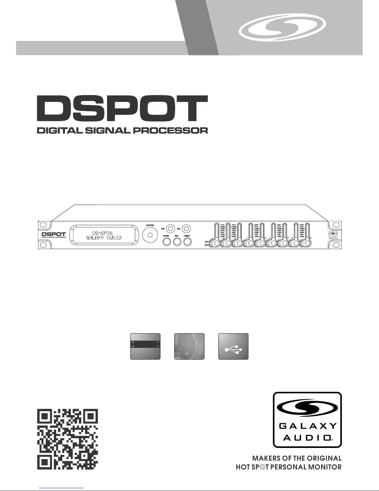
USER’S MANUAL
DS-SP36
3x6 Speaker Processor
USB
USB
(482mm )
19"
DIGITAL
DIGITAL
®
DS-S P36

Contents
Contents
Introduction
Introduction
Thank you for choosing a Galaxy DSPOT Digital Signal Processor. You have joined
hundreds of thousands of other satisfied Galaxy customers. Since 1977 Galaxy Audio’s
professional experience in design and manufacturing ensure our products' quality,
performance and reliability.
For the most up to date manual and information
visit www.galaxyaudio.com.
Introduction..........................................................................................1
Safety Instructions................................................................................ 2
Overview...............................................................................................3
Getting Started with Front Panel Controls........................................ 4 - 28
Using the PC Interface.................................................................. 29 - 34
Volume Controls Table................................................................. 35 & 36
Specifications..................................................................................... 37
1

2
Safety Instructions
Safety Instructions
!
IMPORTANT SAFETY INSTRUCTIONS !
READ these instructions.
KEEP these instructions.
HEED all warnings.
FOLLOW all instructions.
DO NOT use this apparatus near water.
CLEAN ONLY with dry cloth.
DO NOT block any ventilation openings. Install in accordance with the manufacturer's instructions.
DO NOT install near any heat sources such as radiators, heat registers, stoves,
or other apparatus (including amplifiers) that produce heat.
DO NOT defeat the safety purpose of the polarized or grounding-type plug. A
polarized plug has two blades with one wider than the other. A grounding type
plug has two blades and a third grounding prong. The wider blade or the third
prong are provided for your safety. If the provided plug does not fit into your
outlet, consult an electrician for replacement of the obsolete outlet.
PROTECT the power cord from being walked on or pinched, particularly at plugs,
convenience receptacles, and the point where they exit from the apparatus.
ONLY USE attachments/accessories specified by the manufacturer.
1.
2.
3.
4.
5.
6.
7.
8.
9.
10.
11.
This symbol indicates that dangerous voltage
Constituting a risk of electric shock is present
within this unit.
This symbol indicates that there are important
Operating and maintenance instructions in the
Literature Accompanying This Unit
UNPLUG this apparatus during lightning storms or when unused for long periods of
time.
REFER all servicing to qualified service personnel. Servicing is required when the
apparatus has been damaged in any way, such as power-supply cord or plug is damAged, liquid has been spilled or objects have fallen into the apparatus, the apparatus
has been exposed to rain or moisture, does not operate normally, or has been
dropped.
DO NOT expose the apparatus to dripping and splashing. DO NOT put objects filled
with liquids, such as vases, on the apparatus.
USE only with a cart, stand, tripod, bracket, or table
Specified by the manufacturer, or sold with the
Apparatus. When a cart is used, use caution when
moving the cart/apparatus combination to avoid
injury from tip-over.
Remove the batteries from the receiver if the system will not be used for a long
period of time. This will avoid any damage resulting from a defective, leaking
battery.
DO NOT throw used batteries into a fire. Be sure to dispose of or recycle used
batteries in accordance with local waste disposal laws.
12.
13.
14.
15.
16.
17.
®
DS-SP 36
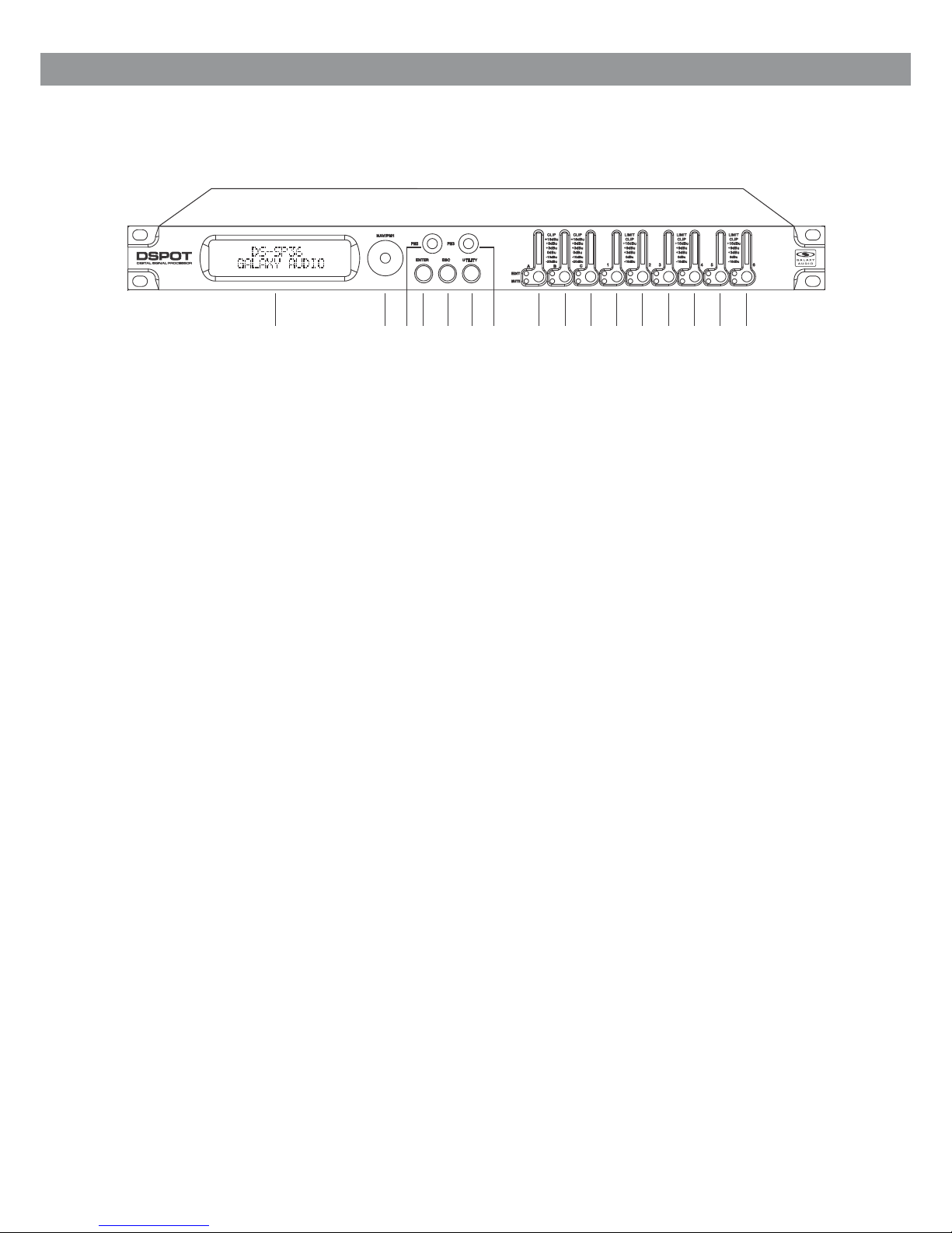
Described below are the functions of the front control buttons and encoders for the DS-SP36.
Overview
1 2
3
5
4
6 7 8 9 10 16
11 12
13
14
15
1 - LCD Display
2 - Navigation/Parameter 1 Key
3 - Parameter 2 Key
4 - Enter Key
5 - Escape Key
6 - Utility Key
7 - Parameter 3 Key
8 - Input A Edit/Mute Button
9 - Input B Edit/Mute Button
10 - Input C Edit/Mute Button
11 - Output 1 Edit/Mute Button
12 - Output 2 Edit/Mute Button
13 - Output 3 Edit/Mute Button
14 - Output 4 Edit/Mute Button
15 - Output 5 Edit/Mute Button
16 - Output 6 Edit/Mute Button
3

4
•
Getting Started
DS-SP36
2x2 WAY X-OVER
DS-SP36
GALAXY AUDIO
DS-SP36
The DS-SP36 has four factory pre-set working modes: “2x2 WAY + SUB”, “2x3 WAY..XOVER”, “6 WAY..
XOVER and “3x2 WAY..XOVER”.
After the initialization, the DS-SP36 will show on the LCD the first of the embedded preset working modes,
or the last one selected prior to the unit being turned off.
First time activation will default to the first of the preset working modes.
A status bar will show the progress of the DS-SP36 initialization process:
When the DS-SP36 is turned ON the device model name will appear in the LCD screen:
Getting Started Using Front Panel Interface

5
• Encoders and ENTER, ESC buttons
The DS-SP36 is equipped with 3 Relative Encoders, “NAV/PM1”, “PM2” and “PM3”. These encoders allow
you to navigate the user interface and edit sections of the processor. They allow the user to navigate within
the screen for the selection of sub-menus, pages and parameters and to select the values to be assigned
during the editing operations.
The “ENTER” and “ESC” buttons allow the user to confirm or NOT confirm the operations performed by the
encoders.
• UTILITY, A/B/C and 1/2/3/4/5/6 buttons
The UTILITY button allows the User to enter the Sub-menus and set the general characteristics of the
Processor. The A, B and C buttons allow the User to enter the Editing Menus of the Processor's Input
Channels and buttons 1, 2, 3, 4, 5 and 6, allow the User to enter the Editing Menus of the Processor's
Output Channels.
The A, B and C buttons as well as the 1, 2, 3, 4, 5 and 6 buttons have double functions dependent on the
push and hold time.
When the A, B and C buttons are pushed and held for more than one second Input Channels A, B or C are
either muted or unmuted. The red LED will illuminate when the Channel is MUTED. When the “MUTE” LED
is OFF, then the related Input Channel is UN-MUTED.
A momentary push of the A, B and C buttons enters the Editing Mode for the Input Channels (see later for
the Input Channel Editing details). The blue “EDIT” LED will now be ON.
When the 1, 2, 3, 4, 5 and 6 buttons are pushed and held for more than one second the Output Channels 1,
2, 3, 4, 5 and 6 are either muted or unmuted. The red LED will illuminate when the Channel is muted. When
the “MUTE” LED is OFF, then the related Output Channel is UN-MUTED.
A momentary push of the 1, 2, 3, 4, 5 and 6 buttons enters the Editing Menu for the Output Channels (see
later for the Output Channel Editing details). The blue “EDIT” LED will now be ON.
• DS-SP36 Menu and Sub-Menu Structures
As stated above, the start-up default screen is the following factory preset:
From this point, sub-menus are accessed using the UTILITY”, “A/B/C”, “1/2/3/4/5/6”, “ENTER” And “ESC”
buttons and all parameters and values are navigated by the “NAV/PM1”, “PM2” and “PM3” encoders.
Please refer to the following menu structures:
DS-SP36
2x2 WAY X-OVER

● Menu “UTILITY” [access by pushing the “UTILITY” button]
From the “Default Screen”, it is possible access the “UTILITY” menu by pushing the “UTILITY” button and
the Sub-Menus pages can be selected by rotating the “NAV/PM1” encoder clockwise and
Counter-clockwise.
Once selecting the sub-menu page, using the “ENTER” button, you can access the Sub-Menu pages.
Again “scrollable” using the “NAV/PM1” encoder and accessible for editing parameters by again pushing
the “ENTER” button. Through the “ESC” button, it is possible at any time, to back through the pages.
Once inside the Sub-Menus pages, several options can be scrolled through using the PM2 or PM3
encoders, and selected/confirmed by pushing the “ENTER” button.
Note: In every Sub-Menu, the option currently selected/running will have an asterisk “ * ” showing to the
right of the description on the LCD screen.
Options that are not selected/running will be displayed without an asterisk.
Pushing the ENTER button, on an unselected option, will mean an asterisk will then appear and this
option will now take over as the currently selected/running option.
System Utilities Sub-menu – this sub-menu allows you to access several operations related to the
DS-SP36 Start Up and General Configuration:
From the “System Utilities Sub-menu”, pushing “ENTER” and then using the “NAV/PM1” encoder for
scrolling will give access to the following pages:
– System Setup: this page allows the selection of the operating mode of the DS-SP36:
The operating mode can be chosen from a selection of 4 Xover options
2x2 WAY + SUB ........... in this operating mode, the DS-SP36 is configured as a 2 Input to 4 Output X-Over,
plus the third Input as SUB, where the 3 Inputs are automatically assigned to the Output as follows:
– Input A to Outputs 1 and 3 [Out1=Low-A and Out3=High-A]
– Input B to Outputs 2 and 4 [Out2=Low-B and Out4=High-B]
– Input C to Outputs 5and 6 [Out5=Sub-A and Out6=Sub-B]
2x3 WAY ..XOVER......... in this operating mode, the DS-SP36 is configured as a 2 Input to 6 Output
X-Over (the Input C is not used), where the 2 Inputs are automatically assigned to the Outputs as follows:
– Input A to Outputs 1,3 and 5 [Out1=Low-A , Out3=Mid-A and Out5=High-A]
– Input B to Outputs 2,4 and 6 [Out2=Low-B , Out4=Mid-B and Out6=High-B]
6
UTILITY MENU
– System Utilities --
SYSTEM UTILITY
– System Setup –

6 WAY ..XOVER...... . in this operating mode, the DS-SP36 is configured as a Mono Input to 6 Output
X-Over, where the Input A is automatically assigned to the Outputs as follow:
– Input A to Outputs 1,2,3,4,5 and 6 [Out1=Near-1, Out2=Near-2, Out3=Mid-1 and Out4=Mid-2, Out5=Far1, Out6=Far-2]
3x2 WAY ..XOVER..... . in this operating mode, the DS-SP36 is configured as a 3 Input to 6 Output X-Over,
where the Inputs are automatically assigned to the Outputs as follow:
– Input A to Outputs 1 and 2 [Out1=Low-A and Out2=High-A]
– Input B to Outputs 3 and 4 [Out3=Low-B and Out4=High-B]
– Input C to Outputs 5 and 6 [Out5=Low-C and Out6=High-C]
By pressing ENTER on the System Setup page and rotating the “PM2” or “PM3” encoder, it is possible to
select all the available X-Over preset modes.
When the “2x3 WAY XOVER” is selected, the “System Setup” page will appear as follows:
To change the desired operating mode for the DS-SP36, the screen must reflect the X-Over required and
then simply pressing the “ENTER” button will bring up the following screen asking for confirmation to load
the selected operating mode:
If confirmed by pressing ENTER, the selected preset mode will load. While the device is configuring the
X-over the following screen will be appear:
The new preset mode will now be shown with an asterisk.
– Input Routing: the DS-SP36 Processor is equipped with 3 Analog Inputs (Balanced Female XLR) and a
stereo S/PDIF Digital Input (RCA connector).
The “Routing Options” page allows you to select the desired Input type:
7
Please Wait.....
Changing Xover
New Xover
[ENTER] to confirm
System Setup
Setup: 2x3 WAY XOVER
SYSTEM UTILITY
– Input Routing –

By pressing ENTER on Input Routing, and then rotating the “PM2” or “PM3” encoders, it is possible to
select the main Inputs for the DS-SP36, allowing the User to choose between Analog or S/PDIF Digital.
The selection can be confirmed by pressing the “ENTER” button. The following screen shows that the
Analog Input has been selected:
– Power-On Procedure: this gives you the ability to select the option that will apply when the DS-SP36
powers up after being switched on.
– Delay Time/Distance: this page allows you to select the measurement unit to be used for the Delays:
Time (in milliseconds “ms”) or Distance (in meters “m”:)
By pressing ENTER and rotating the “PM2” or “PM3” encoder, it is possible to select the measurement unit
to be used for the delay, which will be confirmed by pushing the ENTER button.
The following screen shows the selected delay measurement is Time (milliseconds):
– Software Version:
This page allows you to confirm the Software Version running on the DS-SP36:
8
Input Routing
Source: Analog
Delay Units
Unit: Time (ms)
SYSTEM UTILITY
– Software Version –
SYSTEM UTILITY
– Delay Units –

9
Program Utilities Sub-menu – this sub-menu allows you to access several options related to the
DS-SP36 operating mode and to manage the presets stored and recallable within the Unit:
By pressing the ENTER button and then using the “NAV/PM1” encoder the following pages can be
accessed:
– Recall a Program: this page allows the Loading of a preset program. You can store up to 24 presets in
the DS-SP36 memory:
By pressing ENTER and rotating the “PM2”or “PM3” encoders, it is possible to scroll through all current
available user presets.
If NO USER PRESETS are stored yet, the screen will show the following:
If presets have previously been stored by the user, anyone of them can be recalled:
By using the “PM2” or “PM3” encoder it is possible to scroll through the stored presets. Once the desired
preset appears on the screen select it by pressing the “ENTER” button and this will force the DS-SP36 to
begin to load this selected preset and the following transition screen will appear:
Once loaded the DS-SP36 will exit to the “Recall a Program” screen automatically and the above screen
will disappear:
Note: At any time it is possible to quit the recall action by pressing the “ESC” button.
UTILITY MENU
– Program Utilities –
PROGRAM UTILITY
– Recall a Program –
Recall a Program
No Stored Xovers
[ENTER] to Recall
01: PRESET 1
Loading New Program
01: PRESET 1
PROGRAM UTILITY
– Recall a Program –
10
– Save a Program: this page allows you to store a new preset in the DS-SP36’s memory:
By pressing the ENTER button and rotating the “PM2” or “PM3 encoder, it is possible to scroll through the
previously saved presets and the available empty locations (identified by “Empty Memory”).
If no user presets are stored, the “Save a Program” screen will show empty memory locations for all 1-24
presets as shown in the example below for location 10:
When storing an edited configuration for the DS-SP36, select the location for a preset from the 24 available
by using the “PM2” or “PM3” encoders.
Once the desired location appears on the screen press ENTER again to reach the “Set Program Name”
page.
In this page the User can enter a Preset Name ( up to 16 Characters ) by using the “PM2” or “PM3”
encoder to choose a character and the “NAV/PM1” encoder to move between the 16 available locations for
the character’s positioning.
The current position of the cursor is shown by a “blinking underscore”.
The following is an example of a screen while entering the preset name “Stage 1 2x2” in location 10:
To store the Preset Name press the “ENTER” button again.
The above action will take you to the “Enter to Save” page showing the selected location for
the preset and the final edited name:
Pressing “ENTER” again, will store the preset in the selected location with the chosen name and the
following transition screen will appear on the LCD:
PROGRAM UTILITY
– Save a Program –
Save a Program
10: Empty Memory
Set Program Name
10: Stage 1 2x2 ?
[Enter] to Save
10: Stage 1 2x2 ?
Saving to Memory
10: Stage 1 2x2
11
Once the preset is stored, the above screen will disappear returning to the following screen:
If during the Preset Storing process you want to overwrite an existing memory location, select the desired
location in the “Save a Program” page, then ENTER and you will be asked if you want to overwrite this
preset with the following “[ENTER] to Overwrite” screen displaying the currently stored preset and location:
If you wish to proceed, press “ENTER” again and the DS-SP36 will proceed with the “Set Program Name”
page and the subsequent overwrite on completion of the previously described storing process.
Note: At any time it is possible to quit the storing action by pressing the “ESC” button.
– Delete a Program: this page allows you to delete a preset already stored in the DS-SP36 memory:
By pressing the ENTER button and rotating the “PM2” or “PM3” encoder, it is possible to scroll through the
previously saved presets and the available empty locations (identified by “Empty Memory”).
If no user presets are stored, the “Delete a Program” screen will show empty memory locations for all 1-24
presets as shown in the example below for location 10:
If Presets are available they will be shown in the “Delete a Program” page as follows:
By using the “PM2” or “PM3” encoder it is possible to select a preset to be deleted.
Pressing the “ENTER” button on a selected preset will bring up the “[Enter] to Delete” page, showing the
selected preset.
PROGRAM UTILITY
– Save a Program –
PROGRAM UTILITY
– Delete a Program –
[Enter] to Overwrite
10: Stage 1 2x2 ?
Delete a Program
10: Empty Memory
Delete a Program
10: Stage 1 2x2
 Loading...