

Page 1
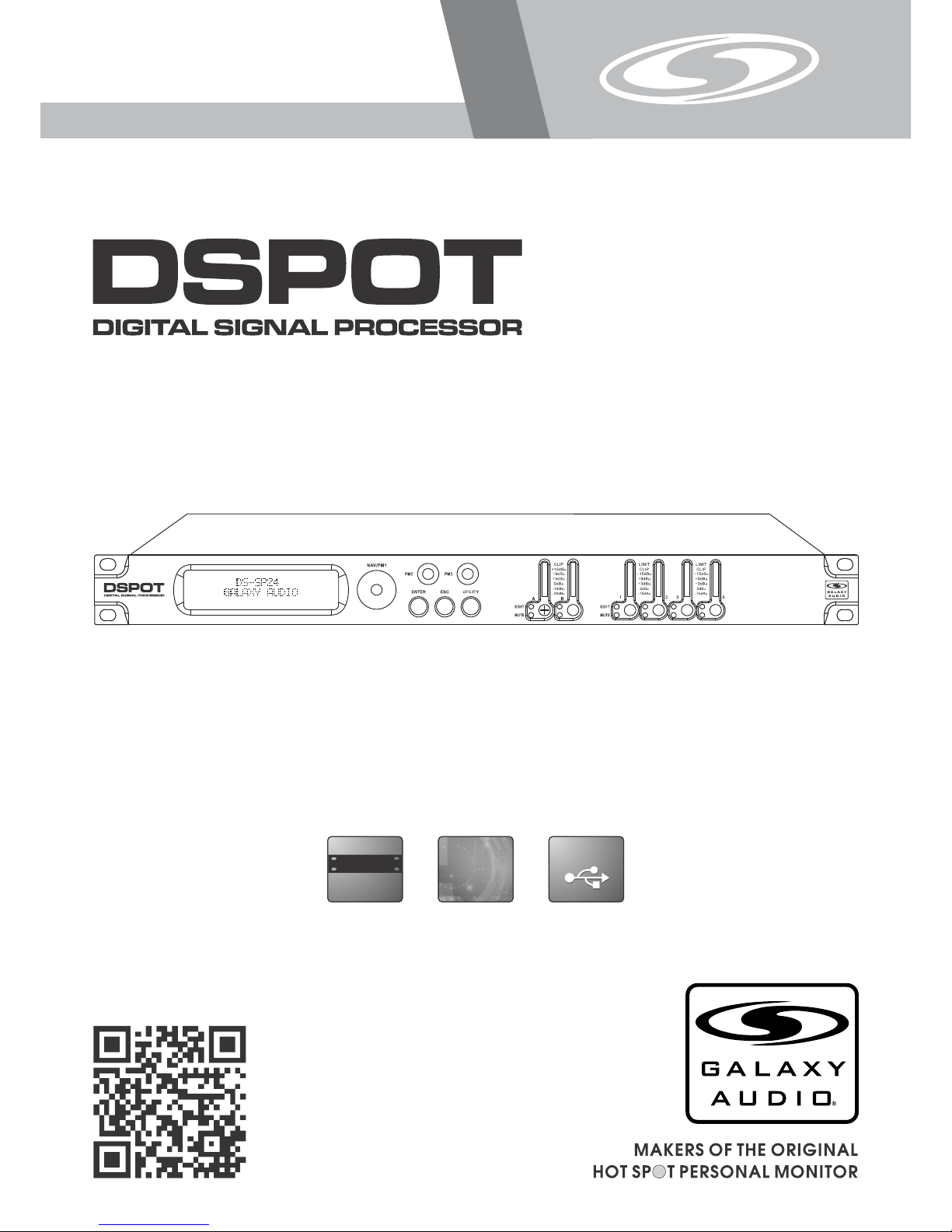
USER’S MANUAL
DS-SP24
2x4 Speaker Processor
USB
USB
(482mm )
19"
DIGITAL
DIGITAL
®
DS-S P24
Page 2

1
Contents
Contents
Introduction
Introduction
Thank you for choosing a Galaxy DSPOT Digital Signal Processor. You have joined
hundreds of thousands of other satisfied Galaxy customers. Since 1977 Galaxy Audio’s
professional experience in design and manufacturing ensure our products' quality,
performance and reliability.
For the most up to date manual and information
visit www.galaxyaudio.com.
Introduction..........................................................................................1
Safety Instructions................................................................................ 2
Overview...............................................................................................3
Getting Started with Front Panel Controls........................................ 4 - 27
Using the PC Interface.................................................................. 28 - 34
Volume Controls Table................................................................. 35 & 36
Specifications..................................................................................... 37
Page 3

2
Safety Instructions
Safety Instructions
!
IMPORTANT SAFETY INSTRUCTIONS !
READ these instructions.
KEEP these instructions.
HEED all warnings.
FOLLOW all instructions.
DO NOT use this apparatus near water.
CLEAN ONLY with dry cloth.
DO NOT block any ventilation openings. Install in accordance with the manufacturer's instructions.
DO NOT install near any heat sources such as radiators, heat registers, stoves,
or other apparatus (including amplifiers) that produce heat.
DO NOT defeat the safety purpose of the polarized or grounding-type plug. A
polarized plug has two blades with one wider than the other. A grounding type
plug has two blades and a third grounding prong. The wider blade or the third
prong are provided for your safety. If the provided plug does not fit into your
outlet, consult an electrician for replacement of the obsolete outlet.
PROTECT the power cord from being walked on or pinched, particularly at plugs,
convenience receptacles, and the point where they exit from the apparatus.
ONLY USE attachments/accessories specified by the manufacturer.
1.
2.
3.
4.
5.
6.
7.
8.
9.
10.
11.
This symbol indicates that dangerous voltage
Constituting a risk of electric shock is present
within this unit.
This symbol indicates that there are important
Operating and maintenance instructions in the
Literature Accompanying This Unit
UNPLUG this apparatus during lightning storms or when unused for long periods of
time.
REFER all servicing to qualified service personnel. Servicing is required when the
apparatus has been damaged in any way, such as power-supply cord or plug is damAged, liquid has been spilled or objects have fallen into the apparatus, the apparatus
has been exposed to rain or moisture, does not operate normally, or has been
dropped.
DO NOT expose the apparatus to dripping and splashing. DO NOT put objects filled
with liquids, such as vases, on the apparatus.
USE only with a cart, stand, tripod, bracket, or table
Specified by the manufacturer, or sold with the
Apparatus. When a cart is used, use caution when
moving the cart/apparatus combination to avoid
injury from tip-over.
Remove the batteries from the receiver if the system will not be used for a long
period of time. This will avoid any damage resulting from a defective, leaking
battery.
DO NOT throw used batteries into a fire. Be sure to dispose of or recycle used
batteries in accordance with local waste disposal laws.
12.
13.
14.
15.
16.
17.
Page 4
®
DS-SP 24
Overview
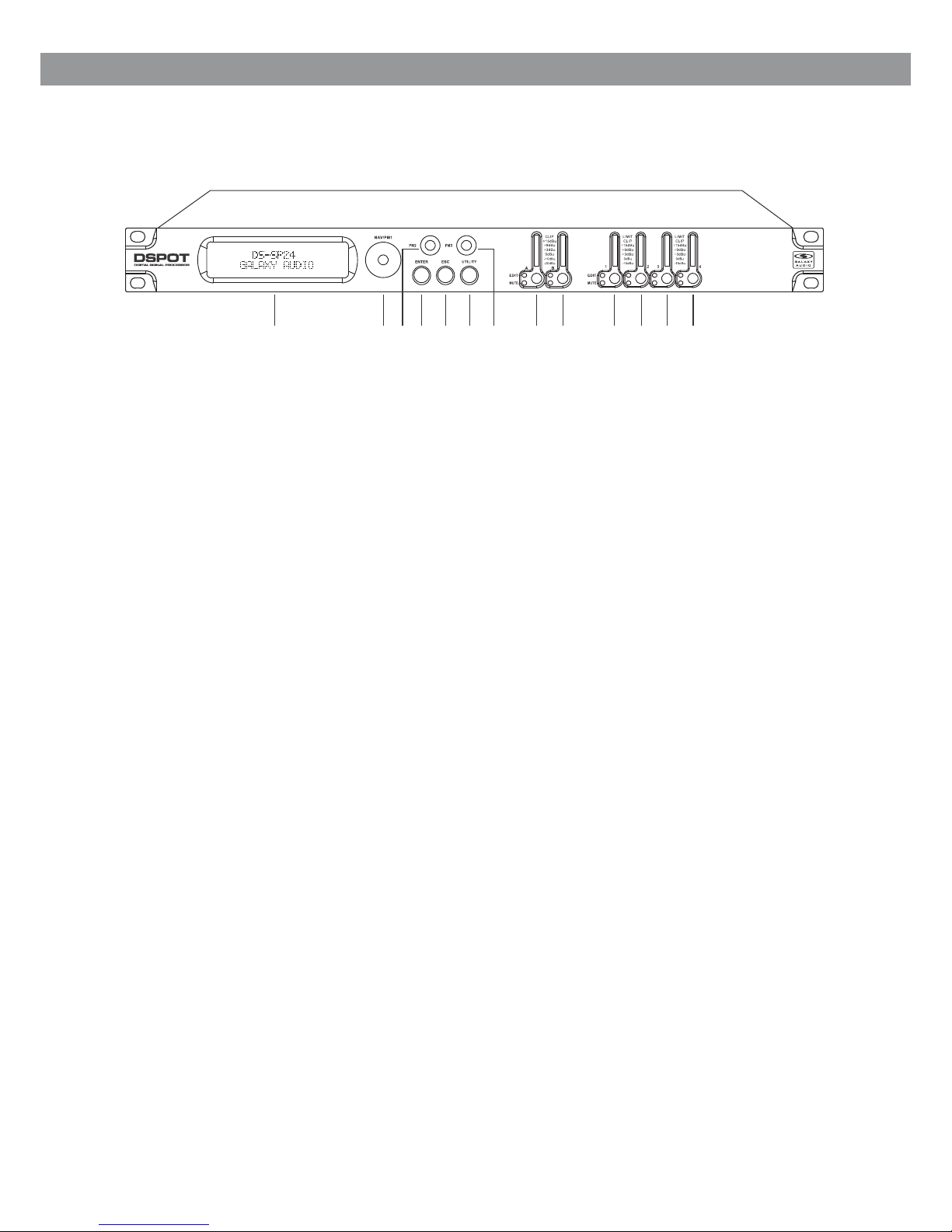
Described below are the f uncti ons of the front panel control buttons and encoders for
The DS-SP24.
1 2
3
4
5
6 7 8 9 10
11 12
13
1 - LCD Display
2 - Navigation/Parameter 1 Key
3 - Parameter 2 Key
4 - Enter Key
5 - Escape Key
6 - Utility Key
7 - Parameter 3 Key
8 - Input A Edit/Mute Button
9 - Input B Edit/Mute Button
10 - Output 1 Edit/Mute Button
11 - Output 2 Edit/Mute Button
12 - Output 3 Edit/Mute Button
13 - Output 4 Edit/Mute Button
3
Page 5
The DS-SP24 has two factory pre- set working modes: “1x2 Way X-Over” and “4 Way X-Over”.
After the initialization, th e DS-SP24 will show on the LCD the first of the embedded preset worki ng
modes, or the last one sele cted pr ior to the unit being turned off.
First time activation will def ault to the first of the preset working modes.
Getting Started
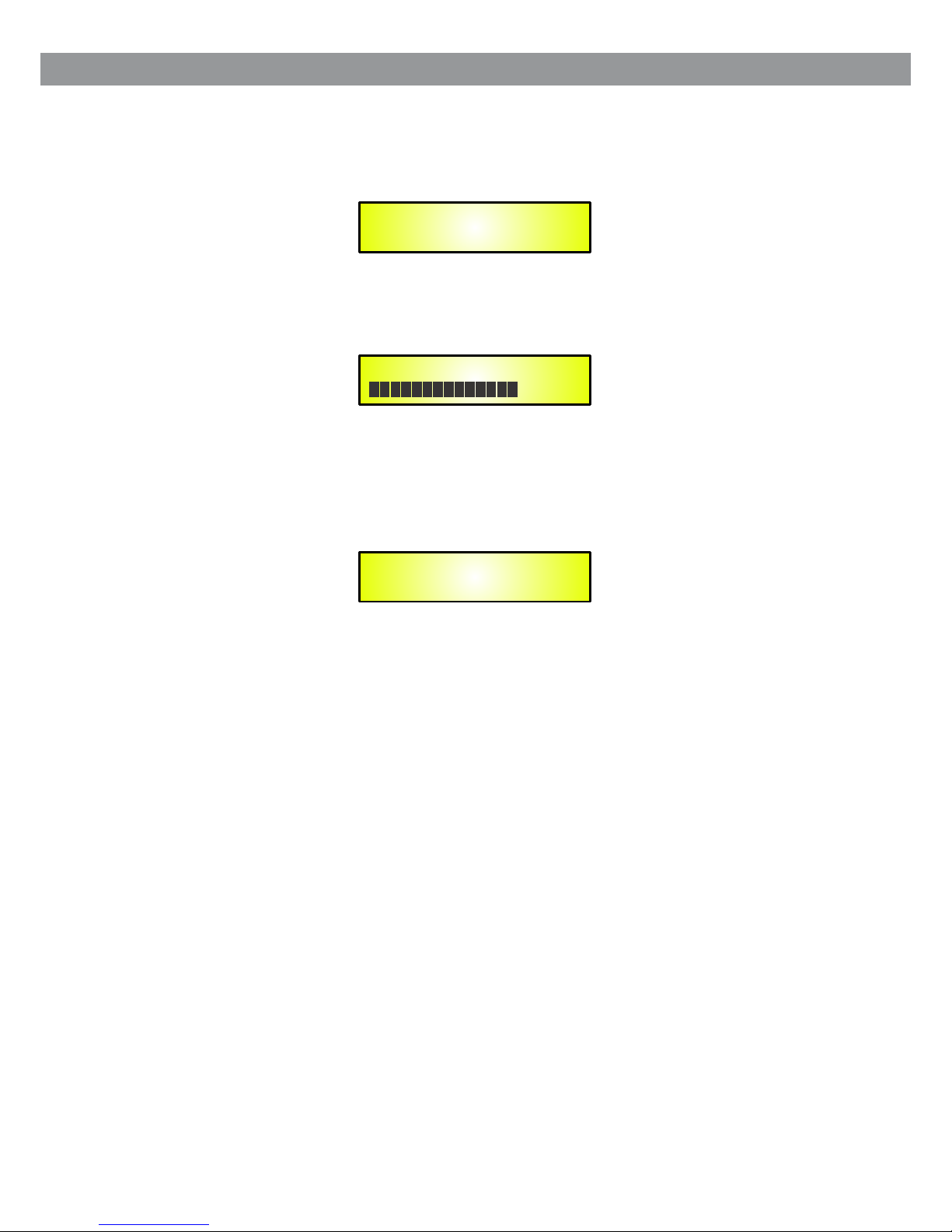
When the DS-SP24 is turned ON the device model name will appear in the LCD screen:
A status bar will show the progress of the DS-SP24 initialization process:
DS-SP24
1x2 WAY X-OVER
DS-SP24
GALAXY Audio
DS-SP24
Getting Started Using Front Panel Interface
4
Page 6

• Encoders and ENTER, ESC buttons
The DS-SP24 is equipped w ith 3 Relative Encoders, “NAV/PM1”, “PM2” and “PM3”. These
encoders allow you to nav igate the user interface and edit sections of the processor. They al low
the user to navigate with in the sc reen for the selection of sub-menus, pages and parameters and t o
select the values to be assigned d uring the editing operations.
The “ENTER” and “ESC” buttons al low the user to confirm or NOT confirm the operations
performed by the encode rs.
• UTILITY, A/B and 1/2/3/4 buttons
The UTILITY button allows t he User t o enter the Sub-menus and set the general characteristics of
the Processor. The A and B buttons allow the User to enter the Editing Menus of the Pr ocess or's
Input Channels and butt ons 1, 2, 3 a nd 4, allow the User to enter the Editing Menus of the
Processor's Output Channel s.
The A and B bu ttons a s well as the 1, 2, 3 and 4 buttons have double functions dependent on th e
push and hold time.
When the A a nd B butt ons are pushed and held for more than one second Input Chann els A or B
are either MUTED or UN-MU TED. The re d LED will illuminate when the Channel is MUTED. When
the “MUTE” LED is OFF, then the relate d Input Channel is UN-MUTED.
A momentary push of the A and B buttons enters the Editing Mode for the Input Channels (s ee
later for the Input Channel Edit ing details).
The blue “EDIT” LED will no w be ON.
When the 1, 2, 3 and 4 buttons are pushe d and held for more than one second the Output Channels
1, 2, 3, and 4 are either MUTED or UN-MU TED. The red LED will illuminate when the Channel is
MUTED. When the “MUTE” LED is OFF, the n the rel ated Output Channel is UN-MUTED.
A momentary push of the 1, 2, 3 and 4 butto ns enters the Editing Menu for the Output Channels
(see later for the Output Channe l Editing details). The blue “EDIT” LED will now be ON.
• DS-SP24 Menu and Sub-Menu Structure s
As stated above, the start-up de fault screen is the following factory preset:
From this point, sub-menus are a ccessed using the “UTILITY”, “A/B”, “1/2/3/4”, “ENTER” and
“ESC” buttons and all par amete rs and values are navigated by the “NAV/PM1”, “PM2” and
“PM3” encoders. Pleas e refer t o the following menu structures:
DS-SP24
1x2 WAY X-OVER
5
Page 7

● Menu “UTILITY” [access by pushing the “ UTILI TY” button]
From the “Default Screen”, it is p ossible to access the “UTILITY” menu by pushing the “UTILITY”
button and the Sub-Menu s pages c an be selected by rotating the “NAV/PM1” encoder clockwis e
and counter-clockwi se.
Once selecting the sub- menu pa ge, using the “ENTER” button will access the Sub-Menu pages,
again “scrollable” us ing the “NAV/PM1” encoder and accessible for parameter editing a gain
pushing the “ENTER” but ton.
Through the “ESC” button, it is an y time possible to go back to the page preceding the “ENTER”
button use.
Once inside the Sub-Men us page s, several options can be scrolled and using the PM2 or PM3
encoders and selected /confirmed pushing the “ENTER” button.
Note: In every Sub-Menu the opti on currently selected/running will have an asteris k “ * ” showi ng
to the right of the description on t he LCD screen.
Options that are not selected/ running will be displayed without an Asterisk.
Pushing the ENTER button on an uns elected option will mean an asterisk will then appear an d this
option will now take over a s the cur rently selected/running option.
System Utilities Sub-menu – th is sub- menu allows to access several operations related to th e
DS-SP24 Start Up and Gene ral Con figuration:
From the “System Utilities Sub -menu”, pushing “ENTER” and then using the “NAV/PM1”encoder
for scrolling will give a ccess to the following pages:
– System Setup: this page allows t he selection of the operating mode of the DS-SP24:
The operating mode can be c hosen from a selection of 2 Xover options
1x 2 WAY ........ .in this operatin g mode, t he DS-SP24 is configured as a 2 Input to 4 Output X-Over,
where the 2 Inputs are auto matic ally assigned to the Outputs as follows:
– Input A to Output s 1/2 [Out1=LowA and Out2=HighA]
– Input B to Outputs 3/4 [Out3=Low B and Out 4=HighB]
4 WAY ....... . .in this operating mo de, the D S-SP24 is configured as a Mono Input to 4 Output
X-Over, where the Input A is automatically assigned to the Outputs as follow:
– Input A to Output s 1/2/3/4 [Out1=Band-1, Out2=Band-2, Out3=Band-3 and Out4=Ba nd-4]
By pressing ENTER on the System Se tup page and rotating the “PM2” or “PM3” encoder, it is
possible to select all th e avail able X-Over preset modes.
UTILITY MENU
- System Utilities -
SYSTEM UTILITY
- System Setup -
6
Page 8

When the “1x2 WAY XOVER” is selec ted, th e “System Setup” page will appear as follows:
To change the desired opera ting mode for the DS-SP24, the screen must reflect the X-Over
required and then simpl y pressing the “ENTER” button will bring up the following scree n askin g for
confirmation to load th e selec ted operating mode:
If confirmed by pressing ENTER t he selected preset mode will load. While the device is configur ing
the X-Over the following scree n will be appear:
The new preset mode will no w be shown with an asterisk.
– Input Routing: the DS-SP24 Processo r is equipped with 2 Analog Inputs (Balanced Female
XLR) and a stereo S/PDIF Digital I nput (RCA connector).
The “Routing Options” p age all ows you to select the desired Input type:
By pressing ENTER on Inpu t Routi ng and then rotating the “PM2” or “PM3” encoders, it is possible
to select the Main Inputs for the DS -SP24, allowing the User to choose between An alog or S/PDIF
Digital.
The selection can be conf irmed b y pressing the “ENTER” button.
The following screen sh ows tha t the Analog Input has been selected:
System Setup
Setup: 1x2 WAY XOVER
*
New Xover
[Enter] to confirm
Please Wait . . . . .
Changing Xover
Input Routing
Source: Analog
*
SYSTEM UTILITY
- Input Routing -
7
Page 9

– Delay Time/Distance: th is page allows you to select the measurement unit to be used for
the Delays: Time (in millis econds “ms”) or Distance (in meters:“m”)
By pressing ENTER and rotating t he “PM2” or “PM3” encoder, it is possible to select the
measurement unit to be us ed for th e delay, which will be confirmed by pushing the ENTER button.
The following screen sh ows the s elected delay measurement is Time (milliseconds):
SYSTEM UTILITY
- Delay Units -
Delay Units
Unit : Time (ms)
*
– Software Version:
This page allows you to con firm th e Software Version running on the DS-SP24:
Program Utilities Sub-menu – this sub -menu allows you to access several options related to
the DS-SP24 operating m ode and t o manage the presets stored and recallable within the Un it:
By pressing the ENTER button and t hen using the “NAV/PM1” encoder the following pages can be
accessed:
– Recall a Program: this page allo ws the Loading of a preset program. You can store up to 24
presets in the DS-SP24 memory:
By pressing ENTER and rotating t he “PM2” or “PM3” encoders, it is possible to scroll through all
current available use r prese ts.
If NO USER PRESETS are stored yet, the scre en will show the following:
SYSTEM UTILITY
- Software Version -
UTILITY MENU
- Program Utilities -
PROGRAM UTILITY
- Recall a Program -
Recall a Program
No Stored Xovers
8
Page 10

If presets have previously bee n stored by the user, anyone of them can be recalled:
By using the “PM2” or “PM3” encode r it is possible to scroll through the stored presets. Once the
desired preset appear s on the sc reen select it by pressing the “ENTER” button and this will force
the DS-SP24 to begin to loa d this se lected preset and the following transitory screen will appe ar:
Once loaded the DS-SP24 w ill exi t to the “Recall a Program” screen automatically and the above
screen will disappear :
Note: At any time it is possible to qu it the recalling action by pressing the “ESC” button.
– Save a Program: this page a llows y ou to store a new preset in the DS-SP24’s memory:
By pressing the ENTER button and r otating the “PM2” or “PM3” encoder, it is possible to scroll
through the previousl y saved p resets and the available empty locations (identifi ed by “Em pty
Memory”).
If no user presets are stored, the “ Save a Program” screen will show empty memory locations
For all 1-24 presets as sho wn in the e xample below for location 10:
[ENTER] to Recall.
01: PRESET 1
Loading New Program . . . . .
01: PRESET 1
PROGRAM UTILITY
- Recall a Program -
PROGRAM UTILITY
- Save a Program -
Save a Program
10: Empty Memory
9
Page 11

When storing an edited co nfigu ration for the DS-SP24, select the location for a preset from the 2 4
available by using the “PM2” or “P M3” encoders.
Once the desired locati on appe ars on the screen press ENTER again to reach the “Set Program
Name” page.
In this page the User can enter a Pres et Name (up to 16 Characters) by using the “PM2” or “PM3”
encoder to choose a chara cter an d the “NAV/PM1” encoder to move between the 16 available
locations for the chara cter’s positioning.
The current position of the curs or is shown by a “blinking underscore”.
The following is an examp le of a scr een while entering the preset name “Stage 1 2x2” in locati on
10:
To store the Preset Name press the “EN TER” button again.
The above action will tak e you to th e “Enter to Save” page showing the selected location for the
preset and the final edit ed name :
Pressing “ENTER” agai n, will s tore the preset in the selected location with the chosen name and
the following transit ory scr een will appear on the LCD:
Once the preset is stored, the abo ve screen will disappear returning to the following screen:
If during the Preset Storing pro cess you want to overwrite an existing memory location select t his
location in the “Save a Program” p age, then ENTER and you will be asked if you want to overwrite
this preset with the following “ [ENTER] to Overwrite” screen displaying the currently sto red pre set
and location:
Saving to Memory. . . . .
10: Stage 1 2x2
Set Program Name.
10: Stage 1 2x2
?
[ENTER] to Save
10: Stage 1 2x2
?
[Enter] to Overwrite
10: Stage 1 2x2
?
PROGRAM UTILITY
- Save a Program -
10
Page 12

If you wish to proceed press “ENTE R” again and the DS-SP24 will go ahead with the “Set Program
Name” page and the subseq uent overwrite on completion of the previously described st oring
process.
Note: At any time it is possible to qu it the storing action by pressing the “ESC” button.
– Delete a Program: this page allo ws you to delete a preset already stored in the DS-SP24
memory:
By pressing the ENTER button and r otating the “PM2” or “PM3” encoder, it is possible to scroll
through the previousl y saved p resets and the available empty locations (identifi ed by “Em pty
Memory”).
If no user presets are stored, the “ Delete a Program” screen will show empty memory locations for
all 1-24 presets as shown i n the exa mple below for location 10:
If Presets are available they wi ll be shown in the “Delete a Program” page as follows:
By using the “PM2” or “PM3” encode r it is possible to select a preset to be deleted.
Pressing the “ENTER” button on a s elected preset will bring up the “[Enter] to Delete.”page
Showing the selected pr eset.
For example, if we want to delete th e preset 10, “Stage 1 2x2”, the screen will be the following:
Confirming the deleti on by pressing “ENTER” again, will force the DS-SP24 to erase the select ed
preset and the followin g trans itory screen will appear:
Once the preset is deleted, the ab ove screen will disappear returning to the following s creen :
PROGRAM UTILITY
- Delete a Program -
Delete a Program
10: Empty Memory
Delete a Program
- 10: Stage 1 2x2 -
[ENTER] to Delete
10: Stage 1 2x2
Erasing Xover Memory. . . . .
10: Stage 1 2x2
PROGRAM UTILITY
Delete a Program
11
Page 13

Note: At any time it is possible to qu it the deleting action by pressing the “ESC” button.
Interface Utilities Sub-me nu – this s ub-menu allows you to define the remote control interface
[USB or RS485] to be used for contro lling the DS-SP24:
From “Interface Utilities” , press “ENTER” to access the Interface Setup.
– Interface Setup: this screen a llows you to choose the remote control protocol for the DS-SP24 .
By pressing “ENTER” and then usi ng the “PM2” or “PM3” encoders you can choose between the
two possible interfac es (USB o r RS485) for the DS-SP24.
Pressing ENTER on a selec ted sou rce will make an asterisk appear to the right of the description
on the LCD as in the followin g example which shows the selected interface as USB.
Security Sub-menu – this sub-m enu allows the User to set the parameters shown, lock the
DS-SP24 and set a Passwor d there fore limiting the unit's functions and controls to those who ha ve
only access to the approp riate P assword.
Press ENTER and then use the “NAV/PM1 ” to scroll between options.
– Show Parameter: Pressing ENT ER from the above menu will access the “Show Parameter”
Sub Menu.
UTILITY MENU
- Interface Utilities -
INTERFACE UTILITY
- Interface Setup -
Interface Setup
Source: USB
*
SECURITY UTILITY
- Show Parameter -
UTILITY MENU
- Security Utilities -
12
Page 14

Press ENTER again and use t he “PM2 ” or “PM3” encoders to scroll between the “be shown” and
“not be shown” options. An a steri sk will highlight which option is selected.
Choosing the “be shown” o ption means that once the unit is locked, you cannot access param eter
editing features, but they wil l be displayed on the LCD screen.
Choosing the “not be show n” opti on means that once the unit is locked, the parameters will not be
shown at all. With this option, wh en trying to access a parameter, the following screen message
will appear:
– Lock Unit: this sub-menu allow s the user to lock the device so no parameters can be edited
or modified.
When the Unit is in an unlock ed cond ition, all parameters will be available for editing. W hen
you select On, all parame ters wi ll be locked and are not available for editing.
When you select lock from the menu , the unit will be locked and the lock menu automatically
exited. The screen will rev ert to th e “Default” showing the current X-Over configuration and
the preset selected and b eside t he preset’s name a “keylock” icon indicating that the
DS-SP24 is locked.
– User Password: from the “User Pa ssword” sub-menu:
Press “ENTER” to access the “Use r Password” page:
Lock Unit
Lock : On
*
Parameter will
not be shown
*
SYSTEM UTILITY
- Lock Unit -
SECURITY UTILITY
- User Password -
User Password
[ ]
13
Page 15

Using the “PM2” or “PM3” encoder s to choose a character and the “NAV/PM1” encoder to move
between available loc ations you can enter a 6 Character Password Name.
The current position of the curs or for the characters to be entered is shown by a “blinking
underscore”.
During this editing pha se, the d isplay is as follows if we were using “DSSP24” as the passwo rd:
The DS-SP24 will exit the “Unit Lo ck” sub-menu and jump to the “User Password” sub-menu page
screen:
If the password entered in the “Co nfirm Password” page matches the one entered in the “Enter
Password” page, the fol lowin g screen will appear.
The Password is now confi gured a nd held in the device’s memory.
The user can now decide to “l ock” th e DS-SP24 by Password, inhibiting the access to ALL
processor functions d epend ing on the setting of the parameter “Password Enable/Disabl e”,
explained in the follow ing paragraph.
– Enable Password: from the “Ena ble Password” sub-menu:
Press “ENTER” to gain access to th e “Enable Password” screen:
User Password
[DSSP24]
SYSTEM UTILITY
- Insert Password -
Confirm Password
[DSSP24]
SYSTEM UTILITY
- User Password -
Enable Password
Password: Disable
*
14
Page 16

Once a Password has been en tered i nto the DS-SP24 through the steps described in the previous
paragraph, it is possib le to “En able” or “Disable” the password function and therefo re lock t he
DS-SP24 restricting access t o all functions.
When a password has been en tered you will be able to select the “Enable” option from the menu
and the unit will not be acce ssibl e for editing. In “Locked by Password Status”, all DS-SP24
functions are inhibit ed to the U ser, including the use of the Mute A/B and MUTE 1/2/3/4 buttons.
The only access availab le is to th e parameters of the input/output channels (accessible by
pressing the edit butto n), ONLY to READ the values (no editing possible) if the “be shown” flag
in the “Show Parameter” Sub-Me nu has been selected.
Once “Locked by Passwor d” the “k eylock” icon will appear on the default LCD screen and no me nu
pages will be accessibl e, with the exception of the “User Password” option.
To regain access to the full op erati on of the DS-SP24, ENTER to the “User Password” screen and
press the UTILITY Button to access t he following screen to enable the correct password to be
entered:
After the correct password has b een entered, you will be able to access the full functionality of t he
DS-SP24, the “lock Icon” will di sappear from the “Default Screen” and automatically the “En able
Password” page will be ba ck to the “ Disable” condition:
If no Password has been set within t he DS-SP24, as described in the previous paragraphs, the
DS-SP24 will not allow yo u to enable any Password, and the choice in the “Enable Password” w ill
be limited to only the “Dis able” o ption.
● Menu “Input A and B” Input Ch annel s Editing [access by pushing the “A/B” buttons]
From the “Default Screen”, it is p ossible to access the “Input A and B” menu by pushin g the “A” or
“B” button. Once the button is pre ssed the related blue “EDIT” LED will turn ON. The Sub-Menu
pages can now be scrolled t hrough by rotating clockwise and counter-clockwise the “N AV/ PM1”
encoder.
For parameter editing i t is nece ssary to press ENTER and an arrow will appear on the left of the
screen “-> ”. Then use the “PM2 ” and “PM 3” encoders for selecting and setting the parameter
values. On some parameters tha t have three independent values, you will also need to use the
“NAV/PM1” encoder, eg filte r parameter settings.
Note: All parameter edi ting ca n be done using the “NAV/PM1”, “PM2”, and “PM3” encoders and the
current shown value of the selec ted option is AUTOMATICALLY loaded during the encoders’ use
and stored as the current value on ce leaving the page.
User Password
[ ]
Enable Password
Password: Disable
*
15
Page 17

Gain page – from this screen it is pos sible t o set the Input Channels Level from -12dB to +6dB,
press ENTER an arrow will a ppear o n the left of the screen “->” then use the “PM1” or “PM2”
buttons.
The value set on this screen will on ly affect the input level of the selected Channel A or B.
The following is an examp le screen for the “Gain” page that has set the Gain of Input Channel A to
+0.0dB:
Delay page – from this page it is poss ible to set the Input Channels Delay Time from 000.0000mS
up to 848.9984mS, by steps of 1mS or 2 0.8uS.
To set the Delay time press ENTER, an ar row will appear on the left of the screen “-> ” then use
the “PM2” encoder to set the Delay Ti me in steps of 1mS and the “PM3” for setting the “fine” Delay
Time in steps of 20.8 microseco nds.
The following is an examp le screen for the “Delay” page where the Delay Time of Input Channel A
is set to 160.1872mS:
EQ: [x] sub-menu – from this sub-m enu it is p ossible to set the Input Channels five available
Parametric or Shelvin g Filte rs.
The DS-SP24 allows the us er to sel ect either Bell or Shelving Parameters and assign them
independently using t he 5 available filters.
In order to select the filter's ty pe, it is n ecessary to have the filter's GAIN=0.0dB, then using the
“PM2” encoder, rotate it “clock wise” in order to decide the Bell filter's Bandwidth, or
“counter-clockwis e” to sel ect the Shelving filter type (Low or High) and its order (1st or 2nd) .
So, in order to define the filter ty pe for the filter number 1 (“x”=1), it is necessary from the above
Screen, to enter the filter's ed iting page pressing the ENTER button, and the screen has to appea r
as follows:
Input-A Gain
-> Gain = + 0.0dB
Input-A Delay
-> Delay = 160.1872mS
Input-A EQ-X
1.00KHz BW1.05 0.0dB
Input-A EQ-1
-> 1.00KHz BW1.06 0.0dB
16
Page 18

In this case, the filter's GAIN= 0.0dB , and being BW=1.05, the current filter selected is a Bell type
now, rotating the “PM2” en coder c lockwise, the parameter BW will range from 0.05 up to 3 for
identifying a bandwid th value for a Bell filter.
If a Bell filter is selected, then t he Gain can be modified from 0.0dB and the BW will range between
0.05 and 3.
If the user wants to select a Shelvi ng filter from the above setting, with the GAIN=0.0dB [if the
GAIN is not 0.0dB, it is necessary t o set it at 0 .0dB using the “PM3” encoder], rotate the “PM2”
Counter-clockwise . Once BW r eaches the 0.05 value, at the next step of the “PM2”
counter-clockwise r otati on, the selection of the Shelving filters will be entered.
Still rotating the “PM2” count er-clockwise, the Shelving filters and their order will be se lectable in
the following sequenc e:
1. 1st Order Low Shelving = -6LoSh [ on the screen]
2. 2nd Order Low Shelving = - 12LoS h [on the screen]
3. 1st Order High Shelvin g = -6HiS h [on the screen]
4. 2nd Order High Shelvin g = -12Hi Sh [on the screen]
Once the desired Shelvi ng filt er is selected, the “PM3” can then be used to select the desired GAIN
and when the GAIN is set at a value differ ent from 0.0dB, then the filter type cannot be changed
until this GAIN is returned to 0.0 dB.
BELL Filter: As an example, if w e want to s et a bell filter within EQ-1, then the BW has to be set at
a desired value of say 1.00 u sing th e “PM2” encoder, the GAIN at say +3dB using the “PM3”
encoder and the center Fr equen cy at say 1.00KHz with the “NAV/PM1” encoder.
The EQ sub-menu screen wi ll show t he following:
Once in the Bell Filter's edit scr een all the filter's parameters can be modified using the
“NAV/PM1”, “PM2” and “PM3” encode rs for editing the Filter's Center Frequency, Bandwidth BW
and Gain.
The Center Frequency of the Para metric Filter can be edited using the “NAV/PM1” encoder, the BW
the “PM2” encoder and the Gain the “ PM3” encoder:
“Center Frequency”: the sele ctable frequencies range is from 20Hz to 20kHz in steps of 1/24 of an
Octave and can be adjuste d by rota ting the “NAV/PM1” encoder.
“Bandwidth BW”: the selectab le BW ran ge is from 0.05 Octave to 3 Octave in steps of 0.05 Octave
and can be adjusted by rota ting th e “PM2” encoder.
“Gain”: the selectable Gain ra nge is from -15dB to +15dB in steps of 0.5 dB and can be adjusted by
rotating the “PM3” encoder.
Low Shelving Filter: As an example if we wa nt to set a low shelving filter within EQ-1 then the
“PM2” encoder has to be rotated co unter-clockwise until the desired Low Shelving fil ter say - 6LoSh
appears on the screen, th e GAIN at s ay +3.0dB using the “PM3” encoder and the High Cut
Frequency at say 1.00KHz with th e “NAV/PM1” encoder.
The EQ sub-menu screen wi ll show t he following:
Input-A EQ-1
->1.00kHz BW=1.00 + 3.0dB
Input-A EQ-1
->1.00kHz -6LoSh + 3.0dB
17
Page 19

Note: Once the desired Lo w Shelv ing filter is selected, the “PM3” can then be used to select the
desired GAIN and when the GAIN is se t at a value different from 0.0dB, then the filter type cannot
be changed until this GAI N is retu rned to 0.0dB.
Once in the Low Shelving Fi lter' s edit screen all the filter's parameters can be modified using t he
“NAV/PM1”, “PM2” and “PM3” encode rs for editing the Filter's High Cut Frequency, Filter's Order
and Gain.
The Hi Cut Frequency of the Low Shel ving Filter can be edited using the “NAV/PM1” encoder, the
Filter's Order can be adjusted b y the “PM2” encoder and the Gain the “PM3” encoder:
“Hi Cut Frequency”: the select able fr equencies range is from 20Hz to 20kHz in steps of 1/24 of an
Octave and can be adjuste d by rota ting the “NAV/PM1” encoder.
“Low Shelving Order”: the selectabl e Low Shelving Filter's range can be selected between the 1st
(Lo-1st.) and the 2nd (Lo -2nd. ) one.
“Gain”: the selectable range o f the Gain is from -15dB to +15dB in steps of 0.5 dB and can be
Adjusted by rotating the “PM3” e ncoder.
High Shelving Filter: As an examp le if we wa nt to set a high shelving filter within EQ-1 then the
“PM2” encoder has to be rotated co unter-clockwise until the desired High Shelving fi lter sa y 6HiSh appears on the scre en, the G AIN at say +3dB using the “PM3” encoder and the Low Cut
Frequency at say 1.00KHz with th e “NAV/PM1” encoder.
The EQ sub-menu screen wi ll show t he following:
Note: Once the desired High Shel ving filter is selected, the “PM3” can then be used to select the
desired GAIN and when the GAIN is se t at a value different from 0.0dB, then the filter type cannot
be changed until this GAI N is retu rned to 0.0dB.
Once in the High Shelving F ilter 's edit screen all the filter's parameters can be modified usin g the
“NAV/PM1”, “PM2” and “PM3” encode rs for editing the Filter's Low Cut Frequency, Filter's Order
and Gain.
The Lo Cut Frequency of the High She lving Filter can be edited using the “NAV/PM1” encoder, the
Filter's Order can be adjusted b y the “PM2” encoder and the Gain the “PM3” encoder:
“Lo Cut Frequency”: the select able fr equencies range is from 20Hz to 20kHz in steps of 1/24 of an
Octave and can be adjuste d by rota ting the “NAV/PM1” encoder.
“High Shelving Order”: the selectab le High Shelving Filter's range can be selected betwee n the
1st (Lo-1st.) and the 2nd (Lo-2n d.) one.
“Gain”: the selectable range o f the Gain is from -15dB to +15dB in steps of 0.5 dB and can be
adjusted by rotating th e “PM3” e ncoder.
Note1: Once the desired o ption s have been selected using the 3 encoders, they are automatical ly
saved as current and stored in the D S-SP24 system status once leaving the page.
Note2: To ex it this page, push the “ESC” button.
Input-A EQ-1
->1.00kHz -6HiSh + 3.0dB
18
Page 20

● Menu “Output 1/2/3/4” Output Channe ls Edit ing [ac cess by pushing the “1/2/3/4” buttons]
From the “Default Screen”, it is p ossible to access the “Output Channel” menu by pressing the “1”
or “2” or “3” or “4” button. Once pres sed, th e related blue “EDIT” LED will turn ON.
The Sub-Menus pages can n ow be scr olled through by rotating clockwise and counter-cl ockwise
the “NAV/PM1” encoder.
For parameter editing i t is nece ssary to press ENTER and an arrow will appear on the left of the
screen “->”. Then use the “PM 2” and “P M3” encoders for selecting and setting the parameter
values. On some parameters tha t have three independent values, you will also need to use the
“PM1” encoder, for examp le for th e filter ’s parameter setting.
Note: All parameter edi ting ca n be done using the “NAV/PM1”,“PM2”, and “PM3” encoders and the
current shown value of the selec ted option is AUTOMATICALLY loaded during the encoders’ use
and stored as the current value on ce leaving the page.
HPF sub-menu – from this sub-men u it is pos sible to set the Output Channels High Pass Filter
(HPF).
The following is an examp le of a HPF s ub-menu screen with the filter set at 24dB Linkwitz/Riley on
Output1... using the name “Hig h” (see later for assigning a Name to the outputs):
The filter's parameters can be m odified by use the “PM2” and “PM3” encoders for editing the
Filter's Low Cut Frequency and t he Filter's Type and Order.
The Low Cut Frequency of the High Pa ss Filter can be edited using the “PM2” encoder and the
Filter's Type and Order can be e dited by using the “PM3” encoder.
“Low Cut Frequency”: the selec table f requencies range is from 20Hz to 20kHz in steps of 1/24 of
an Octave and can be adjust ed by rot ating the “PM2” encoder.
“High Pass Type and Order”: allows yo u to select the X-Over's High Pass Filter Shape and Order.
The available shapes an d orders for the High Pass Filter, that are accessible by rotating the “PM3 ”
encoder, are listed belo w:
– No Cut-Off (High Pass Filter Bypas sed)
– Butwrth 6dB (Butterworth Fil ter 6dB /Oct Slope)
– Butwrth 12dB (Butterworth Fi lter 12dB/Oct Slope)
– Lnk/Ril 12dB (Linkwit z/Ril ey Filter 12dB/Oct Slope)
– Bessel 12dB (Bessel Filter 12d B/Oct Slope)
– Butwrth 18dB (Butterworth Fi lter 18dB/Oct Slope)
– Butwrth 24dB (Butterworth Fi lter 24dB/Oct Slope)
– Lnk/Ril 24dB (Linkwit z/Ril ey Filter 24dB/Oct Slope)
– Bessel 24dB (Bessel Filter 24d B/Oct Slope)
Note1: Once the desired o ption s have been selected using the 2 encoders, they are automatical ly
saved as current and stored in the D S-SP24 system status once leaving the page.
Note2: To ex it this page, push the “ESC” button.
Out-1 High HPE
-> 20.0 Hz Lnk/Ril 24dB
19
Page 21

LPF sub-menu – from this sub-men u it is pos sible to set the Output Channels Low Pass Filter
(LPF).
The following is an examp le of a LPF s ub-menu screen with the filter set at 24dB Linkwitz/Riley on
Output1... using the name “Low ” (see later for assigning a Name to the outputs):
The filter's parameters can be m odified by use the “PM2” and “PM3” encoders for editing the
Filter's High Cut Frequency an d the Filter's Type and Order.
The High Cut Frequency of the Low Pa ss Filter can be edited using the “PM2” encoder and the
Filter's Type and Order can be e dited by using the “PM3” encoder.
“High Cut Frequency”: the sele ctabl e frequencies range is from 20Hz to 20kHz in steps of 1/24
of an Octave and can be adjus ted by ro tating the “PM2” encoder.
“Low Pass Type and Order”: this page al lows you to select the X-Over's Low Pass Filter Shape
and Order.
The available shapes an d orders for the Low Pass Filter that are accessible by rotating the “PM3”
encoder are listed belo w:
– No Cut-Off (Low Pass Filter Bypass ed)
– Butwrth 6dB (Butterworth Fil ter 6dB /Oct Slope)
– Butwrth 12dB (Butterworth Fi lter 12dB/Oct Slope)
– Lnk/Ril 12dB (Linkwit z/Ril ey Filter 12dB/Oct Slope)
– Bessel 12dB (Bessel Filter 12d B/Oct Slope)
– Butwrth 18dB (Butterworth Fi lter 18dB/Oct Slope)
– Butwrth 24dB (Butterworth Fi lter 24dB/Oct Slope)
– Lnk/Ril 24dB (Linkwit z/Ril ey Filter 24dB/Oct Slope)
– Bessel 24dB (Bessel Filter 24d B/Oct Slope)
Note1: Once the desired o ption s have been selected using the 2 encoders, they are automatical ly
saved as current and stored in the D S-SP24 system status once leaving the page.
Note2: To exit this page, push the “ES C” button.
EQ: [x] sub-menu – from this sub-m enu it is p ossible to set the Output Channels seven available
Parametric or Shelvin g Filte rs.
The DS-SP24 allows the us er to sel ect either Bell or Shelving Parameters and assign them
Independently using t he 7 available filters.
Out-1 Low LPE
-> 20.0 Hz Lnk/Ril 24dB
Out-1 Name EQ-X
-> 1.00KHz BW1.05 0.0dB
20
Page 22

In order to select the filter's ty pe, it is n ecessary to have the filter's GAIN=0.0dB, then using the
“PM2” encoder, rotate it “clock wise” in order to decide the Bell filter's Bandwidth, or
“counter-clockwis e” to sel ect the Shelving filter type (Low or High) and its order (1st or 2nd) .
So, in order to define the filter ty pe for the filter number 1 (“x”=1), it is necessary from the above
screen, to enter the filter's ed iting page pressing the ENTER button, and the screen has to appea r
as follows:
In this case, the filter's GAIN= 0.0dB , and being BW=1.05, the current filter selected is a Bell type.
Now, rotating the “PM2” en coder c lockwise, the parameter BW will range from 0.05 up to 3 for
identifying a bandwid th value for a Bell filter.
If a Bell filter is selected, then t he Gain can be modified from 0.0dB and the BW will range between
0.05 and 3.
If the user wants to select a Shelvi ng filter from the above setting, with the GAIN=0.0dB [if the
GAIN is not 0.0dB, it is necessary t o set it at 0 .0dB using the “PM3” encoder], rotate the “PM2”
Counter-clockwise . Once BW r eaches the 0.05 value, at the next step of the “PM2”
counter-clockwise r otati on, the selection of the Shelving filters will be entered.
Still rotating the “PM2” count er-clockwise, the Shelving filters and their order will be se lectable in
the following sequenc e:
1. 1st order Low Shelving = - 6LoSh [ on the screen]
2. 2nd order Low Shelving = - 12LoSh [on the screen]
3. 1st order High Shelvin g = -6HiS h [on the screen]
4. 2nd order High Shelvin g = -12HiSh [on the screen]
Once the desired Shelvi ng filt er is selected, the “PM3” can then be used to select the desired GAIN
and when the GAIN is set at a value differ ent from 0.0dB, then the filter type cannot be changed
until this GAIN is returned to 0.0 dB.
BELL Filter: As an example, if w e want to s et a bell filter within EQ-1, then the BW has to be set at
a desired value of say 1.00 u sing th e “PM2” encoder, the GAIN at say +3dB using the “PM3”
encoder and the center Fr equen cy at say 1.00KHz with the “NAV/PM1” encoder.
The EQ sub-menu screen wi ll show t he following:
Out-1 Name EQ-1
-> 1.00KHz BW1.05 0.0dB
Out-1 Name EQ-1
->1.00kHz BW=1.00 + 3.0dB
21
Page 23

Once in the Bell Filter's edit scr een all the filter's parameters can be modified using the
“NAV/PM1”, “PM2” and “PM3” encode rs for editing the Filter's Center Frequency, Bandwidth BW
and Gain.
The Center Frequency of the Para metric Filter can be edited using the “NAV/PM1” encoder, the BW
the “PM2” encoder and the Gain the “ PM3” encoder:
“Center Frequency”: the sele ctable frequencies range is from 20Hz to 20kHz in steps of 1/24 of an
Octave and can be adjuste d by rota ting the “NAV/PM1” encoder.
“Bandwidth BW”: the selectab le BW ran ge is from 0.05 Octave to 3 Octave in steps of 0.05 Octave
and can be adjusted by rota ting th e “PM2” encoder.
“Gain”: the selectable Gain ra nge is from -15dB to +15dB in steps of 0.5 dB and can be adjusted by
rotating the “PM3” encoder.
Low Shelving Filter: As an exampl e if we wan t to set a low shelving filter within EQ-1 then the
“PM2” encoder has to be rotated co unter-clockwise until the desired Low Shelving fil ter say - 6LoSh
appears on the screen, th e GAIN at s ay +3.0dB using the “PM3” encoder and the High Cut
Frequency at say 1.00KHz with th e NAV/PM1 encoder.
The EQ sub-menu screen wi ll show t he following:
Note: Once the desired Low Shelv ing filter is selected, the “PM3” can then be used to select the
desired GAIN and when the GAIN is se t at a value different from 0.0dB, then the filter type cannot
be changed until this GAI N is retu rned to 0.0dB.
Once in the Low Shelving Fi lter' s edit screen all the filter's parameters can be modified using t he
“NAV/PM1”, “PM2” and “PM3” encode rs for editing the Filter's High Cut Frequency, Filter's Order
and Gain.
The Hi Cut Frequency of the Low Shel ving Filter can be edited using the “NAV/PM1” encoder, the
Filter's Order can be adjusted b y the “PM2” encoder and the Gain the “PM3” encoder:
“Hi Cut Frequency”: the select able fr equencies range is from 20Hz to 20kHz in steps of 1/24 of an
Octave and can be adjuste d by rota ting the “NAV/PM1” encoder.
“Low Shelving Order”: the selectabl e Low Shelving Filter's range can be selected between the 1st
(Lo-1st.) and the 2nd (Lo -2nd. ) one.
“Gain”: the selectable range o f the Gain is from -15dB to +15dB in steps of 0.5 dB and can be
adjusted by rotating th e “PM3” e ncoder.
High Shelving Filter: As an examp le if we wa nt to set a high shelving filter within EQ-1 then the
“PM2” encoder has to be rotated co unter-clockwise until the desired High Shelving fi lter sa y 6HiSh appears on the scre en, the G AIN at say +3dB using the “PM3” encoder and the Low Cut
Frequency at say 1.00KHz with th e “NAV/PM1” encoder.
Out-1 Name EQ-1
->1.00kHz -6LoSh + 3.0dB
Out-1 Name EQ-1
->1.00kHz -6HiSh + 3.0dB
22
Page 24

Note: Once the desired High Shel ving filter is selected, the “PM3” can then be used to select the
desired GAIN and when the GAIN is se t at a value different from 0.0dB, then the filter type cannot
be changed until this GAI N is retu rned to 0.0dB.
Once in the High Shelving F ilter 's edit screen all the filter's parameters can be modified usin g the
“NAV/PM1”, “PM2” and “PM3” encode rs for editing the Filter's Low Cut Frequency, Filter's Order
and Gain.
The Lo Cut Frequency of the High She lving Filter can be edited using the “NAV/PM1” encoder, the
Filter's Order can be adjusted b y the “PM2” encoder and the Gain the “PM3” encoder:
“Lo Cut Frequency ”: the selecta ble fre quencies range is from 20Hz to 20kHz in steps of 1/24 of an
Octave and can be adjuste d by rota ting the “NAV/PM1” encoder.
“High Shelving Order”: the selectab le High Shelving Filter's range can be selected betwee n the
1st (Lo-1st.) and the 2nd (Lo-2n d.) one.
“Gain”: the selectable range o f the Gain is from -15dB to +15dB in steps of 0.5 dB and can be
adjusted by rotating th e “PM3” e ncoder.
Note1: Once the desired o ption s have been selected using the 3 encoders, they are automatical ly
saved as current and stored in the D S-SP24 system status once leaving the page.
Note2: To exit this page, push the “ES C” button.
Vu-Meter page – from this page it i s possi ble to select what is shown on the Output LED meters, by
using the “PM1” or “PM2” encoder s.
The outputs' LED meters can show t he Output signal LEVEL or the Output Limiters' activity.
When the Limiters' activity is s elected, the LED meters will show, from top down, the activity of
the Limiter available o n the output.
When the Output signal Le vel sel ected, the LED meters will show, from bottom up, the level of the
signal:
Name page – from this screen it is pos sible to assign a 6 character name to the Output Channel.
The following is an examp le screen for a “Name” page labeled “Low” for Output Channel 1:
Out-1 Name Vu-Meter
-> Vu-Meter = Limiter Act
Out-1 Name Vu-Meter
-> Vu-Meter Level
Out-1 Low Name
Name = Low
23
Page 25

To Edit press ENTER on the Name Page and t he entering arrow will appear as in the example
below:
The first letter position will b e blinking.
Select the Character po sitio n from the 6 available by rotating the “NAV/PM1” encoder, then by
using the “PM2” or “PM3” encoder i t is possible to select the desired character.
Once you are happy with you r name se lection, press “ENTER” to confirm the edited Name. The
New name will be stored. The fo llowing example shows “Sub” replacing our previous n ame of
“Low”:
Source page – from this page it is pos sible to assign one of the following Inputs to any Output
Channel:
1. Input A
2. Input B
3. Sum of Input A and I nput B
The following is an examp le screen for the “Source” where Input A is assign ed to Out put
Channel 1:
After pressing ENTER an arrow wi ll appear on the left of the screen “->” the Input can be selected
by rotating either the “PM2” or “P M3” encoders.
Gain page – from this screen it is pos sible t o set the Output Channels Level from -12dB to +6dB,
press ENTER an arrow will a ppear o n the left of the screen “-> ” then use the “PM1” or “PM2”
buttons.
The value set on this screen will on ly affect the input level of the selected Channel 1/2/3/4.
The following is an examp le screen for the “Gain” page where the Gain of the Output Channel 1 is
set to +0.0dB
Out-1 Low Name
-> Name = Low
Out-1 Sub Name
Name = Sub
Out-1 Name Source
Source = InA
Out-1 Name Gain
-> Gain = + 0.0dB
24
Page 26

Limiter sub-menu – from this pag e it is pos sible to set the Output Channels Limiter.
The following is an examp le screen for the Limiter page where the Attack Time of the Limiter is
set at 5ms, the Release Time is set at 0. 2Sec and the Limiter Active Threshold is set at +5dB:
Once pushing ENTER the Li miter 's parameters can be modified using the “NAV/PM1”, “PM2” and
“PM3” encoders for editing the L imiter's Attack Time [A], Release Time [R] and Active Threshol d.
Once pushing ENTER the ab ove scr een will change as follows:
The Attack Time [A] can be edited usin g the “NAV/PM1” encoder, the Release Time [R] the “PM2”
encoder and the Limiter Ac tive Threshold the “PM3”
“Attack Time [A]”: the sele ctabl e range of the Limiter's Attack Time is from 5ms to 200ms in steps
of 1ms - from 5ms to 20ms, then 5ms - from 20ms to 30 ms, then 10ms - from 30ms to 100ms, and
20ms - from 100ms to 200ms.
The Limiter's Attack Time can be adj usted by rotating the “NAV/PM1” encoder.
“Release Time [R]”: the sel ectable range of the Limiter's Release Time is from 0.1s to 3s in steps
of 0.1s and can be adjusted b y rotat ing the “PM2” encoder.
“Limiter Active Threshold” : the sel ectable range of the Limiter's Threshold is from +20dB
(Limiter not active) to -10.0d B in steps of 0.2 dB and can be adjusted by rotating the “PM3”
encoder.
Note1: Once the desired o ption s have been selected using the 3 encoders, they are automatical ly
saved as current and stored in the D S-SP24 system status once leaving the page.
Note2: To exit this page, push the “ES C” button.
Delay page – from this page it is poss ible to set the Output Channels Delay Time from 000.0000mS
up to 848.9984mS, by steps of 1mS or 2 0.8uS.
To set the Delay time press ENTER an arr ow will appear on the left of the screen “->”. Then use the
“PM2” encoder to set the Delay Time i n steps of 1mS and the “PM3”, for setting the “fine” Delay
Time in steps of 20.8 microseco nds.
The following is an examp le screen for the “Delay” page where the Delay Time of Output Channe l 1
is set to 160.1872mS:
Out-1 Name Limiter
A: 5ms R: 0.2s +5.0dB
Out-1 Name Limiter
-> A: 5ms R: 0.2s +5.0dB
Out-1 Name Delay
-> Delay = 160.187mS
25
Page 27

Polarity page – from this page it is p ossible to set the Output Channels Polarity, by using the
“PM1” or “PM2” encoders.
The polarity can be “Norm al” or “I nverted” (which means rotated of 180 Degrees).
The following is an examp le of a “Po larity” screen where the Polarity of Output Channel 1 is set to
“Normal”
● Input and Output Channels Last Edited Parame ter Return Function
Once you have escaped out o f param eter editing within the individual Input or Output channels t he
DS-SP24 will remember t his las t editing action on that Channel. When you return for your next
editing action pressi ng the ED IT button on that channel will immediately return you to the s creen
related to this last editing act ion.
This function makes fine tunin g or modifying easier when it is necessary to make a number of
adjustments to the same parame ter in a short time sequence.
● Input Channels and output Channels LINK Func tion
The DS-SP24 is able to perform a uni que LINK MODE between Input Channels as well as a link
between Output Channe ls to ena ble quick and immediate editing (you cannot link outpu t to input
channels).
To link channels when editi ng, you will need to select a “Master” channel that will be the one to be
edited and have it’s parame ters displayed on the LCD screen. You can then select and link o ther
channels (Slaves) tha t you wis h to apply the same changes to.
To enter a link mode session, s elect t he Master channel Edit mode, then link the Slaves by
pressing their relate d Edit bu ttons.
All Linked channels wil l be selected ready for adjustment when their “Blue” LED is lit in th e Editi ng
mode.
Now all Slave channels an d only those selected will modify their parameters accordin gly as you
edit the Master channel .
All other existing para meter s will stay the same within the Slave Channels unless edit ed by thi s
link with the Master chan nel.
Note: The LINK function is NOT a COPY function.
If you want to edit the limiter of the O utput c hannels 1, 2, 3 and 4, you can enter the editing mode of
Output Channel 1 by press ing the r elated Edit button and turning on the “Blue” LED below the
Output Channel 1 LED mete rs. This assigns the “role” of Master and displays this channel’s
Parameters on the LCD:
Out-1 Name Polarity
-> Polarity = Normal
Out-1 Name Limiter
A: 5ms R: 0.2s +5.0dB
26
Page 28

Then press the Edit button of Outp ut Channels 2 and 4, turning on their related “Blue” LED’s. Now
all parameters edited o n Outpu t Channel 1, will also be applied to channels 2 and 4.
If you want to remove one of the linke d channels from the Link, press the related Edit button.
Exiting the editing of the Maste r channel during a Link session will automatically terminat e that
session. The Link will also b e automatically terminated if, during the editing of Output C hannels
You jump across to begin ed iting an Input channel or vice versa.
● Factory Reset
In the event of the password being l ost or any other reason the user may require the unit to be
reset to the original factory se ttings, a “Factory Reset” that will clear all settings of the DS-SP24
and return the device to the origi nal factory setting, is available to the user.
Note: Continuing with t his pro cess will mean the DS-SP24 will re-initialize to the ori ginal f actory
settings and any previo usly st ored information and changed parameters will be perm anently lost.
– Use the following procedure to perfor m the factory reset:
1. While the DS-SP24 is switched O FF, simultaneously press the ENTER+ESC+U TILIT Y bu ttons
on the front panel.
2. Maintain pressure on a ll thre e buttons as you turn the power switch to On and the following LCD
screen appears on the DS- SP24:
3. Release the buttons an d wait fo r the DS-SP24 to re-initialize.
Once completed, the DS-SP24 wi ll resume regular operation as though it was a new unit from the
factory and no previous ly prog rammed parameters will be available for use.
Please Wait. . . . . .
Memory Reset
27
Page 29

Using the DS-SP24 Software.
l
Load the Software “SetupDS-SP24V1.0.0” either with the included CD or via the Galaxy Website.
l
Double click on “Setup”, choose “Run” the software will load.
l
Go to programs and double click on DS-SP24V1.0.0
l
Connect the SDS-SP24 with the USB cable to your computer.
l
Turn on the DS-SP24, the driver software will load automatically.
l
When the driver has finished loading, click once on “connect”.
If you want to continue select “Yes”
Choose your connection type.
Then Click on Connect.
Using the PC Interface
28
Page 30

To edit Double click on the desired device in the ID list.
The Main Page will load.
The software will look for active devices and show them in a list.
29
Page 31

The device will also be locked out from front panel control at this point.
You may choose to “Load Preset from PC”, “Save Preset to PC”, “Store Preset to Device”, “Read Preset
from Device”
You can name a device by selecting edit device name.
From the main page you can choose the section you want to adjust by clicking on the associated block.
Once you have accessed the block you can adjust parameters by either using the sliders, arrows, or typing
the values in directly.
30
Page 32

Select the gain block to access the gain and polarity of the inputs and outputs.
Select the input block to access input and output naming.
31
Page 33

Select the Delay block to access the input and output delays.
Select the PEQ block to access the input and output filters.
32
Page 34

Select the Limiter Block to access the Limiter page.
33
Page 35

You can select the meters to show either, level or limiter function.
You can copy parameters between channels by selecting the copy input or copy output block and then
selecting the source parameters and the destination.
34
Page 36

● USB/RS485 Remote Control pro tocol f or Preset Changing and Gain/Volume controls
The following is the HEX Co de for co ntrolling the DS-SP24 recall presets and master volume
control:
Preset Changing:
CMD_RECALL_PRESET: CM D=1BH
A. The User has to send the follo wing Command, including the number of the preset to load on the
unit:
TX:
XX = 0,..,31 (ID device)
Npreset=0,...,23 Presetn umber
The DS-SP24's microcontrol ler will check if the Preset is initialized (available o r not yet c reated...)
B. If YES, then the microcontrolle r will send back to the User (eg Crestron/AMX Remote Control..)
the same frame used by the command .
RX:
So in this case, if the user gets back E XACTLY what was sent, the preset is existing and loaded on
the unit.
C. If the preset that the user wante d to load is NOT YET INITIALIZED (not yet created, so not
Available...), the micr ocontroller will notify that to the user, sending back the follo wing fr ame:
RX:
STX ID_M ID_N CMD D0 D1 D2 D3 D4 D5 D6 D7 ETX
F0H C1H XX 1BH NPreset 00H 00H 00H 00H 00H 00H 00H F7H
STX ID_M ID_N CMD D0 D1 D2 D3 D4 D5 D6 D7 ETX
F0H C1H XX 1BH NPreset 00H 00H 00H 00H 00H 00H 00H F7H
STX ID_M ID_N CMD D0 D1 D2 D3 D4 D5 D6 D7 ETX
F0H C1H XX 1BH FFH 00H 00H 00H 00H 00H 00H 00H F7H
Volume Control Table
35
Page 37

Input Gain and Output Volume Control:
UPDATE GAINS-PHASE: CMD= 01H
A. The User has to send the follo wing Command, including the value to be assigned to “Vol”, for
modifying the Input Gain (Chn = 0, 1 ) or the Output Volume (Chn = 2, 3, 4, 5).
Also the Output signal Phase can b e modified:
TX:
XX = 0,..,31 (ID device)
Chn=0,...,5: Channel selected, 0, 1 =In1, In2; 2,...,5=Out1,..,Out4; when Channel 0, 1 selected,
then Vol=Input
Gain, when Channel 2, 3, 4, 5 selected, the n Vol = Outpu t Vol .
Phs= Phase only if the Chn> 1; Value=0, 1 wher e 0=dir ect, 1=inverse (180')
Vol= Gains from 0 to 180 (-12dB/ +6dB ste p 0.1dB )
B. If the command has been properl y executed and the Gain/Volume modified, then the
microcontroller wil l send back to the User (eg Crestron/AMX Remote Control..) the same fram e
used by the command:
RX:
STX ID_M ID_N CMD D0 D1 D2 D3 D4 D5 D6 D7 ETX
F0H C1H XX 01H Chn 00H 00H 00H 00H 00H Phs Vol F7H
STX ID_M ID_N CMD D0 D1 D2 D3 D4 D5 D6 D7 ETX
F0H C1H XX 01H Chn 00H 00H 00H 00H 00H Phs Vol F7H
36
Page 38

● DS-SP24 Technical Specificati ons
The DS-SP24 Digital Spe aker Pr ocessor is based on a powerful analog and digital DSP platfo rm
having the following sp ecifications:
Analog Input Signal: ChA/ChB Bal. Fem ale XLR
Maximum Input Level: +20dBu
Analog Output Signal: Ch1/Ch2/Ch3 /Ch4 Bal. Male XLR
Maximum Output Level: +20dBu
Digital Processing (DSP): SA M3716 , 24bits (data) x 96 bits (coeff.)
A/D Converters: AKM539 2, 24bi ts
D/A Converters: AKM4396, 24bits
Sampling Frequency: 48kHz
S/PDIF Stereo Digital Input: 32kHz, 4 4.1kHz and 48kHz Sources Accepted
S/N: 110dBA
THD+N: 0.005%
Frequency Response (Bypass ): 20Hz – 20kHz (+- 1 dB)
Power Supply: Switching Powe r Supply
Remote Control: USB, RS485
Dimensions: 9.25" x 19" x 1.75" (2 34.95 x 482.6 x 44.45 mm)
Weight: 6.3lb (2.86kgs)
USB
USB
FUSE
800mA
Specifications
37
Page 39

Page 40

1-800-369-7768 www.galaxyaudio.com
V02072014
Printed in China
© Copyright Galaxy Audio 2014
WARRANTY Information can be viewed online at
http://www.galaxyaudio.com/warranty.php
THREE YEA R LIMITED WARRA NT Y
Specifications in this manual are subject to change without notice.
For the most up to date manual and information
visit www.galaxyaudio.com.
DS-SP24
 Loading...