

Page 1
USER’S MANUAL
®
®
POWER
ADS
SET
AF LEVEL
-30 -20
-12
-6 -3 0 3
dBu
ADS
SET
AF LEVEL
-30 -20
-12
-6 -3 0 3
dBu
ADS
SET
AF LEVEL
-30 -20
-12
-6 -3 0 3
dBu
ADS
SET
AF LEVEL
-30 -20
-12
-6 -3 0 3
dBu
GROUP CHANNEL
INFRARED
BATT
Page 2

Contents
Contents
DHX & DHXR4 System
DHX & DHXR4 System
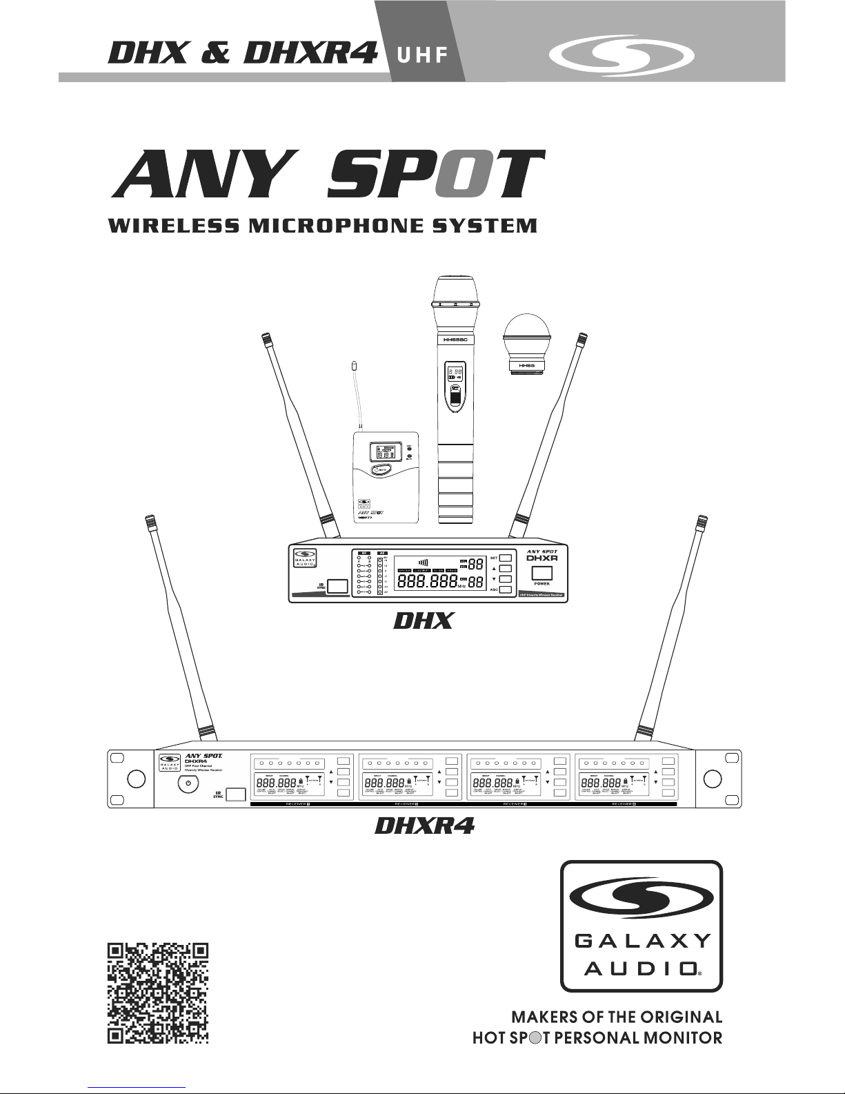
DHX and DHXR4 Systems
Thank you for choosing the Galaxy Audio DHX or DHXR4 Wireless Microphone
Syste m. You h ave j oined hu ndreds o f tho usa nds o f other satisfie d Galaxy
customers. Since 1977 Galaxy Audio’s professional experience in design and
manufacturing ensure our products quality, performance and reliability.
For users who need an advanced UHF wireless system, the DHX and DHXR4
provides an excellent solution. With 120 selectable channels, they are perfect for
applications such as live shows, br oadcast, meetings, & musica l instruments. Touch
buttons and liquid crystal displays allow for a quick and simple system setup. The
“Quick Start Guide” included in your system will provide all the details you need to
operate the system efficiently.
Frequency Band
Most countries closely regulate the radio frequencies used in the transmission of
wireless infor mation. The se re gulations stat e whi ch de vices c an us e whi ch
frequencies, and help to limit the amount of RF (radio frequency) interference in all
wireless communications. The DHXR4 offers 120 selectable channels within either
the 584-607MHz (Code D), 655-679MHz (Code L) or 518-535MHz (Code N) frequency
ranges.
To facilitate system setup and protect against RF interference, e ach system comes
with multiple predefined frequency groups an d channels. When using a single
receiver/transmitter, the operating frequency will generally not have to be changed.
In an installation with multiple receivers/transmitters, each set must operate on a
separate channel from the others. The group and channel system provides an
optimum frequency spread when using multiple receiver/transmitter systems.
DHXR System Components..................................................1
DHXR4 System Components................................................2
Rack-Mounting the DHXR.....................................................3
Rack-Mounting the DHXR4...................................................4
Functions of the DHXR Receiver...........................................5
Functions of the DHXR4 Receiver.........................................6
HH65/HH65SC Handheld Transmitter...................................7
MBP77 Body Pack Transmitter..............................................8
SM-W77 Wireless Shockmount Base....................................9
DHXR System Setup..........................................................10
DHXR4 System Setup.........................................................11
Setting Up Multiple Receivers.............................................12
Troubleshooting.................................................................13
Specifications.....................................................................14
Accessories and Replacement Parts...................................15
Frequency Chart.................................................................16
DTV Frequency Ranges & FCC Consumer Alert..................17
Page 3
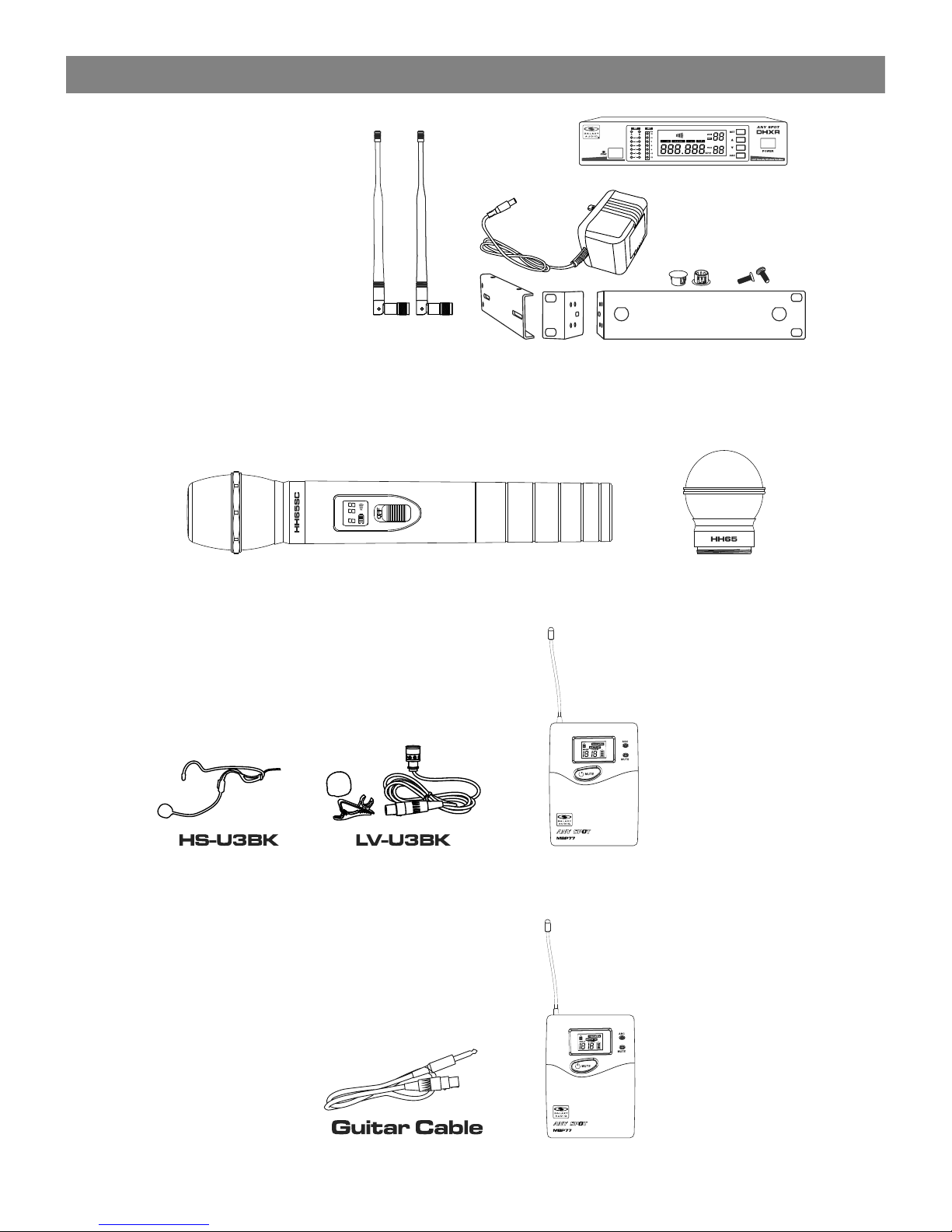
All DHXR Systems Include:
DHXR Rece iver
Power Sup ply
Two Antenna s
MREWD Sin gle/D ual Rack Kit
Quick Start Guid e
System Components
System Components
1
DHXR System Components
DHXR System Components
HH65/HH65 SC Handheld System includes:
Handhel d Mic Tran smitter with HH65 Dynam ic or
HH65SC Su per Car dioid Condenser,
Interch angea ble Heads
GROUP CHANNEL
INFRARED
BATT
DHX/77 Guit ar system inclu des:
MBP77 Bod y Pack Tra nsmitter and
¼" to Mini 3-pin Gui tar Cable.
MBP77 Lav/Heads et Systems incl udes:
MBP77 Bod y Pack Tra nsmitter.
Mic (Choi ce of Uni L avalier or Uni Headset)
This is just a sample
of the many headset
and lav options available
from Galaxy Audio.
Page 4
System Components
System Components
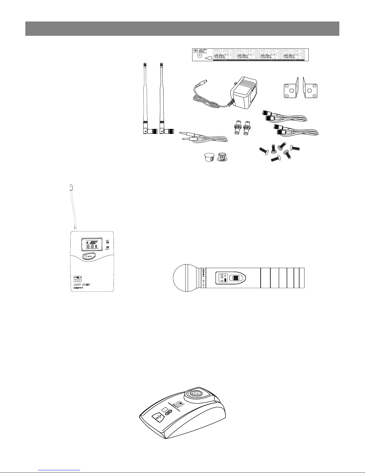
DHXR4 System Components
DHXR4 System Components
Transmitter Options:
HH65 / HH65 SC Hand held Mic/Transmitter
MBP77
Body Pack
Transmitter
Visit our website
www.galaxyaudio.com
to see all of our great
headset & lavalier
options
SM-W77 Wireles s Shockmount Base
OFF
ON
CHANNEL
INFRARED
BATT
All DHXR4 Systems Include:
DHXR4 Receiver
¼" to ¼" Audio Cable
Power Supply
Two Antennas
Extension Kit x2
Rack Ears
Quick Start Guide
Two Antenna Plugs
6 Screws
®
POWER
ADS
SET
AF LEVEL
-30 -20
-12
-6 -3 0 3
dBu
ADS
SET
AF LEVEL
-30 -20
-12
-6 -3 0 3
dBu
ADS
SET
AF LEVEL
-30 -20
-12
-6 -3 0 3
dBu
ADS
SET
AF LEVEL
-30 -20
-12
-6 -3 0 3
dBu
22
Page 5
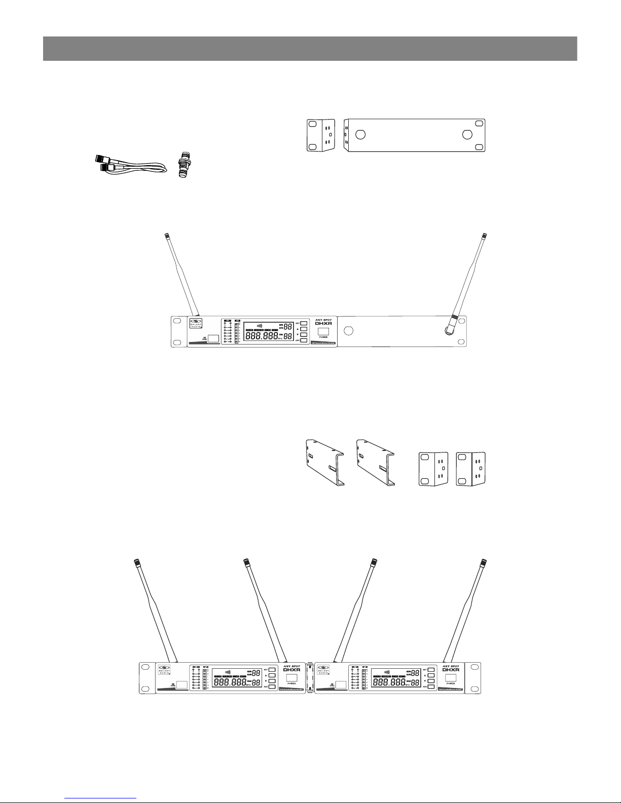
Included MREWD Single/Dual Rack Kit
Long and Short Rack Ears needed
for Single Unit Mounting
BNC CONNECTOR & CABLE:
For front mounting antenna to rack ears.
Part# AS-EXT50/BNC (optional)
Rack Brac kets fo r mounting
Two Rece ivers side by side
Included Parts : MREWD
Rack-Mounting a Single DHX Receiver
Rack Mounting the DHXR
Rack Mounting the DHXR
3
Rack-Mounting Two DHX Receivers
Included MREWD Single/Dual Rack Kit
Two Short Rack Ears and Two Coupler
Halves needed for Dual Unit Mounting
Page 6
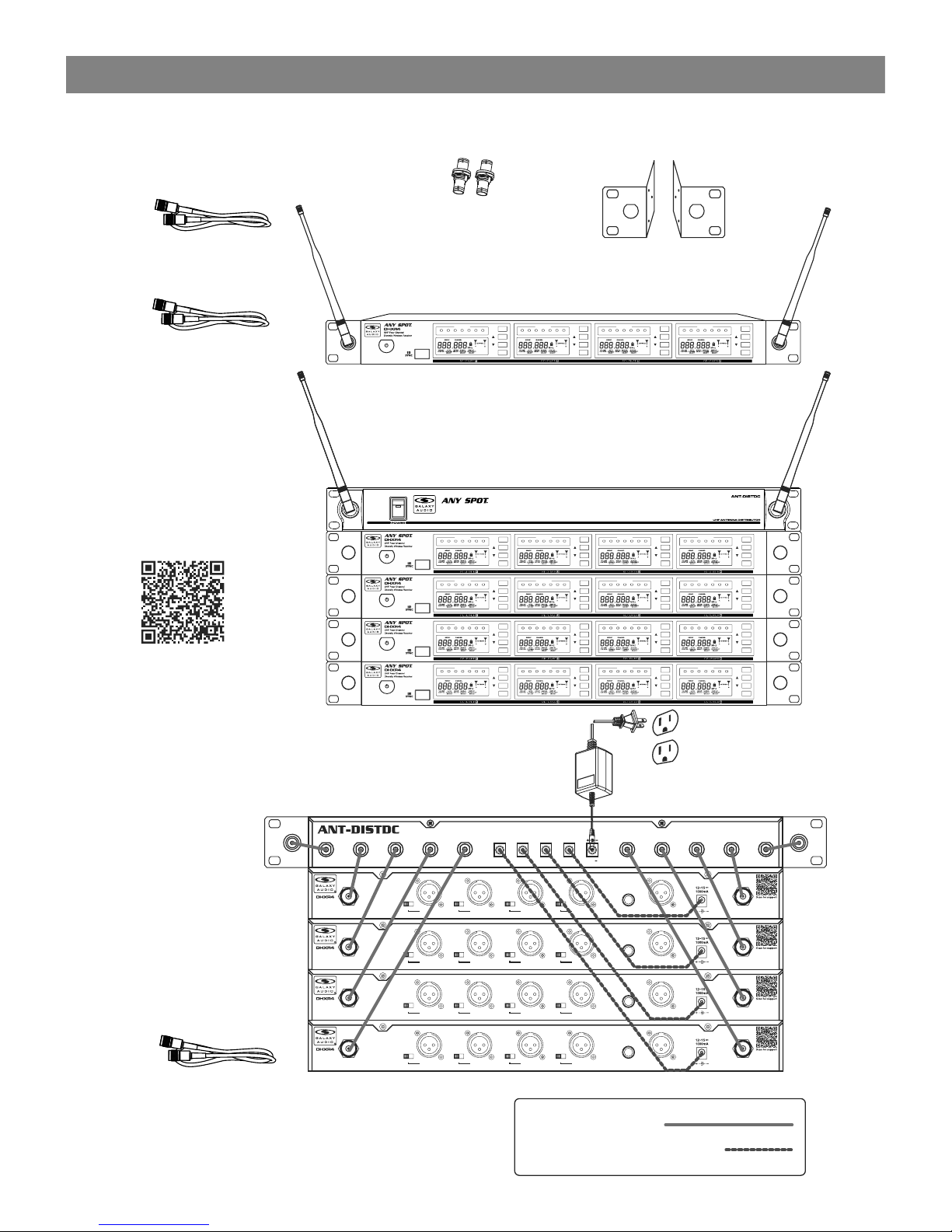
Rack-Mounting the Receiver
Maintain a line of sight between
transmitter and antenna.
Ten BNC connecting cables (included)
Two BNC feed through connectors (included)
Four power supply cables (included)
Rack Ears
MREDHXR4
Antenna
Extension
Cable
EXTBNC
Rack-Mounting the DHXR4 Receiver
Rack-Mounting the DHXR4 Receiver
4
Shown with optional
ANT-DISTDC
antenna distributor.
Four DHXR4 receivers
®
Panel mount
BNC feed-through
connectors
CN-BNCPM
1. BNC Cables
2. Power Supply Cable
12~18
3000mA
OUTPUT4
600mA
OUTPUT3
600mA
OUTPUT2
600mA
OUTPUT1
600mA
DCIN
H H H H
M M M M
L L L L
SENS SENS SENS SENS
Channel 4
XLR balanced
Antenna-B Antenna-AChannel 3
XLR balanced
Channel 2
XLR balanced
Channel 1
XLR balanced
4 in 1 Mix
XLR balanced
4 in 1 Mix
Unbal output
H H H H
M M M M
L L L L
SENS SENS SENS SENS
Channel 4
XLR balanced
Antenna-B Antenna-AChannel 3
XLR balanced
Channel 2
XLR balanced
Channel 1
XLR balanced
4 in 1 Mix
XLR balanced
4 in 1 Mix
Unbal output
H H H H
M M M M
L L L L
SENS SENS SENS SENS
Channel 4
XLR balanced
Antenna-B Antenna-AChannel 3
XLR balanced
Channel 2
XLR balanced
Channel 1
XLR balanced
4 in 1 Mix
XLR balanced
4 in 1 Mix
Unbal output
H H H H
M M M M
L L L L
SENS SENS SENS SENS
Channel 4
XLR balanced
Antenna-B Antenna-AChannel 3
XLR balanced
Channel 2
XLR balanced
Channel 1
XLR balanced
4 in 1 Mix
XLR balanced
4 in 1 Mix
Unbal output
ANT-1
ANT-2 ANT-3 ANT-4 ANT-5 ANT-6 ANT7- ANT-8
ANTENNA-A
ANTENNA-B
ANT-DISTDC Info
The ANT-DISTDC will provide
DC power to operate up to
4 DHXR4 or DHXR Receivers.
®
POWER
ADS
SET
AF LEVEL
-30 -20
-12
-6 -3 0 3
dBu
ADS
SET
AF LEVEL
-30 -20
-12
-6 -3 0 3
dBu
ADS
SET
AF LEVEL
-30 -20
-12
-6 -3 0 3
dBu
ADS
SET
AF LEVEL
-30 -20
-12
-6 -3 0 3
dBu
®
POWER
ADS
SET
AF LEVEL
-30 -20
-12
-6 -3 0 3
dBu
ADS
SET
AF LEVEL
-30 -20
-12
-6 -3 0 3
dBu
ADS
SET
AF LEVEL
-30 -20
-12
-6 -3 0 3
dBu
ADS
SET
AF LEVEL
-30 -20
-12
-6 -3 0 3
dBu
®
POWER
ADS
SET
AF LEVEL
-30 -20
-12
-6 -3 0 3
dBu
ADS
SET
AF LEVEL
-30 -20
-12
-6 -3 0 3
dBu
ADS
SET
AF LEVEL
-30 -20
-12
-6 -3 0 3
dBu
ADS
SET
AF LEVEL
-30 -20
-12
-6 -3 0 3
dBu
®
POWER
ADS
SET
AF LEVEL
-30 -20
-12
-6 -3 0 3
dBu
ADS
SET
AF LEVEL
-30 -20
-12
-6 -3 0 3
dBu
ADS
SET
AF LEVEL
-30 -20
-12
-6 -3 0 3
dBu
ADS
SET
AF LEVEL
-30 -20
-12
-6 -3 0 3
dBu
®
POWER
ADS
SET
AF LEVEL
-30 -20
-12
-6 -3 0 3
dBu
ADS
SET
AF LEVEL
-30 -20
-12
-6 -3 0 3
dBu
ADS
SET
AF LEVEL
-30 -20
-12
-6 -3 0 3
dBu
ADS
SET
AF LEVEL
-30 -20
-12
-6 -3 0 3
dBu
Page 7

5
1 2 3 4 5 6
Infrared (IR) Wi ndow.
Antenna A i ndicator light.
Indicates when An tenna A is active
Antenna A R F stren gth indicator.
Antenna B RF s treng th indicator.
Antenna B in dicat or light.
Indicates when An tenna B is active.
Audio Sign al Leve l indicator.
LCD Scree n.
See “DHXR System S etup” on Page 10.
1
2
3
4
5
6
7
ASC Sync But ton.
Press to initiat e IR connection between
receiver and tra nsmitter.
System Menu Down B utton.
See “DHXR System S etup” on Page 10.
System Menu Up But ton.
See “DHXR System S etup” on Page 10.
System Setup But ton:
See “DHXR System S etup” on Page 10.
On/Off Switch.
8
9
10
11
12
Antenna Jack B 50 .
XLR Output Jack.
¼" Output Jack.
Mute Threshold Fine Adjustment.
This is set at the factory and usually does not need to be adjusted.
If interference signals are received, this threshold value may be increased
by turning the pot clockwise with small screwdriver until the RF signal lamp goes out.
DC Power Input Connector.
Antenna Jack A 50 .
1
2
3
4
5
6
11
2 3 4 5 6 7 8
9
1 10
12
DHXR Receiver Features
Front Panel
Functions of the DHXR Receiver
Functions of the DHXR Receiver
Rear Panel
Page 8

6
DHXR4 Receiver Features
Front Panel
Functions of the DHXR4 Receiver
Functions of the DHXR4 Receiver
H H H H
M M M M
L L L L
SENS SENS SENS SENS
Channel 4
XLR balanced
Antenna-B Antenna-AChannel 3
XLR balanced
Channel 2
XLR balanced
Channel 1
XLR balanced
4 in 1 Mix
XLR balanced
4 in 1 Mix
Unbal output
Antenna Jac k B
Channel 4 Adjustme nt of Squelch Level
Channel 4 XLR O utput Jack
Channel 3 Adjustme nt of Squelch Level
Channel 3 XLR O utput Jack
Channel 2 Adjustme nt of Squelch Level
Channel 2 XLR O utput Jack
Channel 4 Adjustme nt
of Squelch Le vel
Channel 1 XLR O utput Jack
1/4" Mix Outp ut Jack
Balanced Mi x Output Jack
DC Power Inpu t Jack
Antenna Jac k A
10
11
12
13
7
6
5
4
3
2
1
8
9
®
POWER
ADS
SET
AF LEVEL
-30 -20
-12
-6 -3 0 3
dBu
ADS
SET
AF LEVEL
-30 -20
-12
-6 -3 0 3
dBu
ADS
SET
AF LEVEL
-30 -20
-12
-6 -3 0 3
dBu
ADS
SET
AF LEVEL
-30 -20
-12
-6 -3 0 3
dBu
The 3 position Sensitivity Adjustment helps to prevent extraneous RF from being picked up and
turned into audio when the transmitter is off. The higher level will reduce the useable distance of
the transmitter from the receiver. Use the lowest setting that keeps the receiver quiet when the
transmitter is off.
The DHXR4 now utilizes Tone Key Squelch. This keeps the receiver channel muted until it
receives the inaudible tone from its transmitter. This keeps the channel quiet when the
transmitter is off, even if something else is transmitting on the frequency on which the channel
is set.
On/Off Switch
1
2
3
4
5
6
7
Infrared (I R) Window
Audio Level M eter
LCD Panel
System Setu p Button. Please see
“DHXR4 Syst em Setup” on Page 11
System Menu U p button. Please see
“DHXR4 Syst em Setup” on Page 11
ADS Sync Butt on
Press to init iate IR connection bet ween
Receiver an d Transmitter.
10
8
9
Antenna B Ind icator
Lights when An tenna B is active.
System Menu D own button. Please see
“DHXR4 Syst em Setup” on Page 11
Antenna A Indicator
Lights when An tenna A is a ctive.
The receive r will switch
to whicheve r Antenna has
the best sign al.
Rear Panel
Page 9
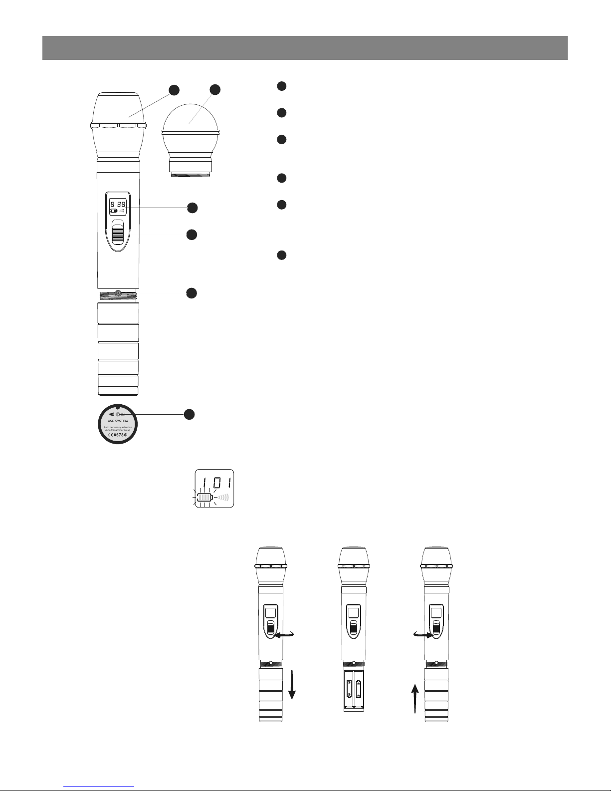
Condenser Mic
Dynamic Mic
LCD Screen. Please See the “system setups”
on pages 10 or 11.
Power Switch
Microphone Input Sensitivity Control.
Left turn for output level decrease, right
turn for output level increase.
IR Port receives infrared beam to synchronize
frequencies.
1
2
3
4
5
6
Functions:
1
2
3
4
5
6
BATT
GROUP CHANNEL
INFRARED
Changing Batteries:
Batteries should be replaced when LCD indicator flashes.
Unscrew the battery cover as shown below. Install
two AA alkaline batteries, while observing correct polarity
indicators in the battery tray.
Expected life for two AA alkaline batteries is 8 hours.
HH65/HH65SC Handheld Transmitter
HH65/HH65SC Handheld Transmitter
7
GROUP CHANNEL
INFRARED
BATT
OFF
OFFOFF
AASIZE
AASIZE
OFF
Page 10

8
9
Wearing the Body Pack Transmitter:
Clip the transmitter to a belt . For best results, slide the
transmitter down until the belt is pressed against the
base of the clip. Or, slide a guitar strap through the
transmitter clip ,as shown.
10
11
Changing batteries:
Expected life for Two Alkaline batteries is approximately
6 hours. Replace batteries when the Green Power LED
and the LCD Battery Indicator (shown below) begin to
blink.
Features
Antenna.
LCD panel. Please See the “system setups”
on pages 10 or 11.
Power/ASC/ Low Battery Indicator.
Constant Green: Power ON.
Flashing Green: IR ADS in progress, or Low Batteries.
Mute Indicator.
Constant Red: Audio Muted.
Power/Mute Button.
Push and Hold for Power On/Off.
Push once for Mute On/Off.
IR Window.
Receives IR signals (ADS) to synchronize with Receiver.
Select Button. Please See the “system setups”
on pages 10 or 11.
3-pin Microphone Input Jack.
Gain Adjustment Switch.
Three gain settings are available. Choose the
appropriate setting for your application:
Mic: Microphone
0dB: Guitar with passive pickups
-10dB: Guitar with active pickups,
or Line Level Signals.
Note: To prevent accidental power or mute changes
during a performance, you may set the Lock function by
a simultaneous press and release of buttons 5 and 7.
This will disable all buttons and a “lock” icon will appear in
the LCD. Repeat procedure to return to normal operation.
1
2
3
4
5
6
7
8
MBP77 Body Pack Transmitter
MBP77 Body Pack Transmitter
8
9
select
1
7
7
5
6
1
2
3
4
10
11
Page 11

9
SM-W77 Wireless Shockmount Base
SM-W77 Wireless Shockmount Base
Functions:
1. To turn on the SM-W77, press the large dark grey power button. A green light on the button
will illuminate, then the LCD window will also illuminate and indicate the current setting of the 16
possible channels.
2. To change the frequency, press and hold either the up or down button until the channel
number flashes. Then use the up or down button to change the channel to the desired number.
3. Once the SM-W77 is set, use the frequency chart to find the corresponding group and channel
for the DHXR or DHXR4 receiver, and set the receiver accordingly.
4. The grey button is used to power the transmitter on and off. If the green light on the power
button turns red, the battery has fallen below the required voltage and should be replaced
immediately.
CODE D Frequency Chart CODE L Frequency Chart
SM-W77D DHXR SM-W77L DHXR
Page 12

Group and Channel Selection: Press and Hold the SET button. The
Group number will flash. Press or to choose the appropriate frequency
group, as shown on the left ; press (SET) again , (CHANNEL) flashes,
press or to choose the appropriate channel, as shown on the left .
For best results when operating multiple systems, set all systems to a
single group: then set each system to a unique channel within that group.
Receiver Volume Setting:
The receiver has an electronic volume control. When in the normal display,
press or to control the output volume (64 steps total) as shown at
left.
Normal Display:
Volume and Frequency, as shown at left .
LED columns to the left of the LCD display show RF & AF Levels.
Automatic Transmitter Setup:
Once the desired channel is set on the Receiver, you may allow the
Transmitter channel to be set automatically. Note: only one Transmitter
may used with each Receiver.
Turn on the Transmitter. Position the Transmitter IR window directly in front
of the Receiver IR window. The IR window of the MBP77 Body Pack is
located under the battery door while the IR window of the HH65 Handheld
is located at the bottom end of the mic body. Press the ASC Button on the
Receiver. The ASC Icon will flash in the Receiver LCD. The RF Meters
will light when the synchronisation is complete. The Group and Channel
number of the Receiver should now be displayed in the Transmitter LCD.
With the HH65, turn on the transmitter after pressing the ASC button.
Note: The Transmitter must be within half a meter distance from
the Receiver during IR ASC automatic channel setting.
HH65 and MBP77 Transmitter Status Display
Battery Status:
Battery Status Indicators for both the Handheld and Body Pack
Transmitters feature Four Level Displays as shown in .
Group and Channel Display:
After completing the ASC, both the Handheld and Body Pack Transmitters
will display the Group and Channel numbers selected as shown in .
Normal Display:
Both Handheld and Body Pack Transmitters will display Group and
Channel numbers as well as Battery Status as shown in .
Handheld
Transmitter
Body Pack
Transmitter
GRO UP C HANNE L
SCA N
FRE Q
GRO UP C HANNE L
SCA N
FRE Q
GRO UP C HANNE L
SCA N
FRE Q
GRO UP C HANNE L
SCA N
FRE Q
GRO UP C HANNE L
SCA N
FRE Q
GRO UP C HANNE L
SCA N
FRE Q
1
2
3
4
5
1
1
2
2
3
3
4
5
Receiver Pr ogramming
DHXR System Setup
DHXR System Setup
1
2
3
10
Page 13

DHXR4 System Setup
DHXR4 System Setup
Handheld
Transmitter
Body Pack
Transmitter
1
2
3
1
2
3
4
5
GROU P CHAN NEL
ANTE NNA
A
B
GROU P
SELE CT
SELE CT SELE CT
CHAN NEL CONT ROL
AUTO VOLU ME
MANU AL
CHAN NEL
FREQ UENCY
DISP LAY
MHz
SELE CT
GROU P CHAN NEL
ANTE NNA
A
B
GROU P
SELE CT
SELE CT SELE CT
CHAN NEL CONT ROL
AUTO VOLU ME
MANU AL
CHAN NEL
FREQ UENCY
DISP LAY
MHz
SELE CT
GROU P CHAN NEL
ANTE NNA
A
B
GROU P
SELE CT
SELE CT SELE CT
CHAN NEL CONT ROL
AUTO VOLU ME
MANU AL
CHAN NEL
FREQ UENCY
DISP LAY
MHz
SELE CT
GROU P CHAN NEL
ANTE NNA
A
B
GROU P
SELE CT
SELE CT SELE CT
CHAN NEL CONT ROL
AUTO VOLU ME
MANU AL
CHAN NEL
FREQ UENCY
DISP LAY
MHz
SELE CT
GROU P CHAN NEL
ANTE NNA
A
B
GROU P
SELE CT
SELE CT SELE CT
CHAN NEL CONT ROL
AUTO VOLU ME
MANU AL
CHAN NEL
FREQ UENCY
DISP LAY
MHz
SELE CT
Group and Channel Selection:
Press “SET” button twice, “GROUP SELECT” will display,
press or to choose the appropriate frequency group.
Press “SET”again , “MANUAL CHANNEL SELECT” will
display, press or to choose the appropriate channel.
For best results when operating multiple systems, set all
systems to a single group, then set each system to a unique
channel within that group. However, depending on the
environment, this may not be possible.
Auto Frequency Finder Function on the Receiver:
Choose “AUTO CHANNEL SELECT” by pressing “SET” once,
then press or . Receiver will automatically find a clear
frequency with no interference.
Receiver Volume Setting:
The receiver has an electronic volume control. Press or
from the normal display (00 to 63)
Normal Display:
Frequency and Antenna A or B (when receiving RF).
Transmitting Frequency Automatic Setup:
Place the Transmitter “IR” window to face the Receiver “IR”
window. Then press the “ADS” button on the desired Receiver.
The Transmitter will automatically match the Receiver frequency.
Attention: The distance between the Receiver and Transmitter
IR windows should be less than 0.5m during the ADS IR setup.
When setting up multiple Transmitters/Receivers, activate the
ADS function of only one Transmitter and Receiver at a time.
1
2
3
4
5
MBP77 Transmitter Status Display
Battery Status:
Battery Status Indicators for both the Handheld and Body
Pack Transmitters feature Four Level Displays.
Group and Channel Display:
After completing the ADS, both the Handheld and Body Pack
Transmitters will display the Group and Channel numbers
selected.
Normal Display:
Both Handheld and Body Pack Transmitters will display
Group and Channel numbers as well as Battery Status.
1
2
3
11
Receiver Pr ogramming
Page 14

Setting Up Multiple Receivers
Setting Up Multiple Receivers
1) Power on any pre-existing wireless systems and transmitters (excluding DHXR/DHXR4).
2) Power on the DHXR/DHXR4 Receiver, do not turn on the DHXR/DHXR4 transmitters.
3) On the DHXR or the first channel of the DHXR4, press the SET button until scan flashes,
then press either the up or down button. The receiver will then scan for an open frequency
channel within the group selected, and stop on the frequency.
When the DHXR4 Receiver has been set to a clear frequency, use the ADS/ASC feature to
sync the receiver frequency to the transmitter.
4) Power on the transmitter for the DHXR or the first channel of the DHXR4, and sync it to the
receiver using the ADS/ASC feature. Turn the transmitter on and aim its IR window towards
the IR SYNC window at the left side of the DHXR/DHXR4, then press the ADS/ASC button
on the desired receiver channel, and the transmitter will automatically set to the receiver’s
frequency.
5) For using more channels on the DHXR4, leave the first channel transmitter on and repeat
steps 3 and 4 for the second DHXR4 channel.
6) Continue this process for the 3rd and 4th channel of the DHXR4.
7) If the receiver is unable to find open frequencies on the group selected, you will need to set
one or more receiver channels to another group, and then scan again.
8) To change the group, press the SET button twice, the group number will begin to flash. Use
the up or down button to select another group. Then proceed as before.
9) If you have more than one DHXR or DHXR4 system, continue the process as described,
adding one channel at a time.
If you have more DHXR or DHXR4 systems to tune follow the same procedure on each
one, always leaving the previous system transmitter on.
4
3
3
®
UHF Four Channel
Diversity Wireless Receiver
POWER
®
®
POWER
ADS
SET
AF LEVEL
-30 -20
-12
-6 -3 0 3
dBu
ADS
SET
AF LEVEL
-30 -20
-12
-6 -3 0 3
dBu
ADS
SET
AF LEVEL
-30 -20
-12
-6 -3 0 3
dBu
ADS
SET
AF LEVEL
-30 -20
-12
-6 -3 0 3
dBu
2
4
3
3
2
Using the auto scan function to find clear frequencies for your
DHX or DHXR4 System
12
Page 15

Troubleshooting
Maintain a line of sight between transmitters and antennas.
Avoid placing the receiver near metal surfaces or any digital equipment (CD players,
computers, etc).
Keep the receiver away from the wall and at least 1m from the ground.
Cellular telephones and two-way radios can interfere with the operation of wireless
systems. Do not use these devices in close proximity to the wireless systems.
Tips for Improving System Performance
Issue Indicator Status Solution
Turn on transmitter.
Make sure the batteries are installed
correctly.
Make sure AC adapter is securely
plugged into electrical outlet and into
DC input connector on rear panel of
receiver.
Increase receiver volume.
Make sure Gain adjustment switch on
the transmitter is set correctly (applies
only to MBP77 Body Pack.)
Make sure Transmitter and Receiver
are set to the same frequency.
Make sure Transmitter is in range of
Receiver.
Make sure no large metal objects are
near Transmitter or Receiver.
Change the batteries in transmitter.
Remove nearby sources of RF
interference (CD players, computers,
in-ear monitor systems, etc.)
Use Auto Scan to find a clear Channel
Adjust Transmitter Gain and Receiver
Volume as necessary.
Replace Transmitter batteries.
Transmitter LCD off.
Receiver LCD off.
Receiver indicates RF.
Receiver indicates No RF,
Transmitter LCD is on.
The battery power indicator
light on LCD flashes.
Receiver Indicates RF.
Transmitter power indicator
light flashing on the LCD.
Distortion level
increases gradually.
Sound level different
from cabled guitar or
microphone, or when
using different guitars.
Distortion or
unwanted noise.
No sound or faint
sound.
Troubleshooting
Troubleshooting
13
Page 16

14
Specifications
Specifications
System
Frequency Range: CODE D 584~607 MHz
CODE L 655~679 MHz
CODE N 518~535 MHz
Transmitter Output Level: 10 dBm
Band: UHF
Operating Range Under Typical
Conditions: 300'
Note: actual range depends on RF signal
absorption, reflection, interference, and
battery characteristics.
Audio Frequency Response (+/-3dB):
60Hz~16kHz
Total Harmonic Distortion (+/-30kHz deviation,
1KHz tone): <1%
Dynamic Range: >90dB A-weighted
Operating Temperature Range:
14ºF to 122ºF (-10º C to +50º C)
Note: battery characteristics may limit
this range:
Body Pack Transmitter:
Max Audio Input Level:
0 dBV maximum at mic gain position.
+10 dBV maximum at 0 dB gain position.
+20 dBV maximum at 10 dB gain position.
Gain Adjustment Range: 30dB
Input Impedance: 470k
Dimensions: 3.5" x 2.6" x 1"
(89 x 65 x 24 mm)(HxWxD)
Weight: 3.0 oz (85 g) (without batteries)
Power Requirements:
2 “AA” alkaline or rechargeable Batteries
batteries
Battery Life:
About 6 hours
Shockmount Transmitter:
Number of Channels: 16
Number of Simultaneous Systems:
4-8 across multiple bands
Carrier Frequency Bandwidth: Code D 584-607 MHz
Code L 655-679 MHz
Operating Range : 150'
Number of Inputs: 1
Type of Connections: XLRF
Indicators: Low battery LED
Frequency Response: 60Hz~16kHz
SNR: 102dB (a)
THD+N: <1%
RF Power: 10 mW
Phantom Power: 9VDC
Power Requirements: 2 “AA” size
alkaline or rechargeable batteries
Power Consumption: 110mA
Dimensions: 1.8" x 4.3" x 5.88"
(45.75 x 109.25 x 149.17 mm)(HxWxD)
Weight: 1.6 lbs (without batteries)
Handheld Transmitter:
Max Audio Input Level: 0dBV
Dimensions: 9.5" x 2.1" dia.
(242 x 54 mm dia.)
Weight: 10.6 oz (300 g) (without batteries)
Power Requirements: 2 “AA” size
alkaline or rechargeable batteries
Battery Life: About 6 hours
DHXR Receiver:
Audio Output Level (+/-30kHz deviation,
1kHz tone): XLR connector (into 600 load)
-12dBV ¼" connector (into 3k load) -18dBV
Output Impedance: XLR connector 200
¼" connector 1k
XLR Output: Impedance balanced
Pin1: Ground (cable shield)
Pin2: Audio
Pin3: No Audio
Sensitivity: -93dBm for 30dB
Image Rejection: >90dB
Dimensions: 1.7" x 8.3" x 6.3"
(45 x 212 x 160 mm)(HxWxD)
Weight: 31.75 oz (900 g)
Power Requirements:
12-18 V DC at 1000mA, supplied by external
power supply.
DHXR4 Receiver:
Audio Output Level (+/-30kHz deviation,
1kHz tone): XLR connector (into 600 load)
-12dBV ¼" connector (into 3k load) -18dBV
Output Impedance: XLR connector 200
¼" connector 1k
XLR Output: Impedance balanced
Pin1: Ground (cable shield)
Pin2: Audio
Pin3: No Audio
Sensitivity: -93dBm for 30dB
Image Rejection: >90dB
Dimensions: 1.7" x 16.1" x 11"
(45 x 410 x 280 mm)(HxWxD)
Weight: 7.3 lbs (3.3 kg)
Power Requirements:
12-18 V DC at 1000mA, supplied by external
power supply.
Page 17
15
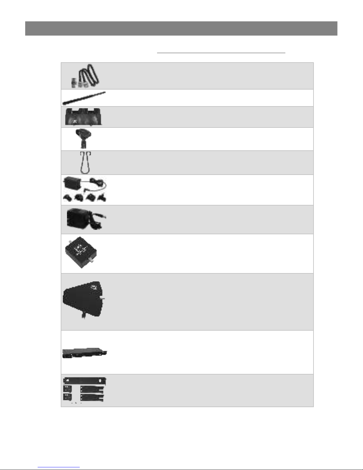
Accessories and Replacement Parts
Accessories and Replacement Parts
AS-EXTBNC - BNC Connector and Cable for front mounting the
antennas on the DHX and DHXR4.
Many of these parts and accessories may be found and purchased from the Galaxy Audio
website in either the Galaxy Store (www.galaxyaudio.com/parts-and-accessories) or in the
accessories tab of each products web page.
AS-ANTBNC - Replacement BNC Antenna for use with Galaxy Audio
Wireless Personal Monitors and Wireless Microphones.
WMC-CGR - DC Charger for HH65, HH65SC, & MBP77. Charges 2
body packs or handhelds at once.
MICCLIPSI - Wireless Microphone Clip
AS-UA12-14.5 - Universal Power Supply for Replacement Power
Supply for AS-900, AS-1100, VES, VSC, ECD, ECM, PSE, DHX,
DHXR4, & CTS. Includes adapters for most other countries.
AS-CLIP1576 - Replacement Belt Clip for MBP77
ANT-DISTDC - Wireless Microphone Antenna Distribution with Power
Distribution for four wireless receiver. Expands wireless microphone
systems by splitting one pair of antennas to allow up to four single
channel receivers to use the same antennas. Works with PSE, CTS,
DHX and DHXR4 series.
PS-13.5-.35.5 - Replacement Power Supply for AS-900, AS-1100,
VES, VSC, ECD, ECM, PSE & DHX.
ANT-PDL - Directional antenna used to decrease interference to
other equipment. Frequency range 500-900MHz The UHF wide-band
(500-900 MHZ) directional LPDA (log periodic dipole array) antenna
reduces outside interference while providing increased send/receive
signal range. Each antenna paddle is matched to 50 ohms
impedance with a low-loss BNC connector; 7dBi gain. For permanent
or temporary installation; mounts to 5/8"-27 threads.
ANT-AMPMIC - Antenna Amplifier utilizes phantom power and a low
noise design which covers all UHF frequency points from 500mHz to
900mHz. Metal construction, requires phantom power (9VDC), 50
ohm input/output impedance.
MREWD - Rack kit for dual mounting two DHXR receivers into a
single rack space.
Page 18
16
http://www.galaxyaudio.com/assets/uploads/media/WPM-WMS_Freqs.jpg
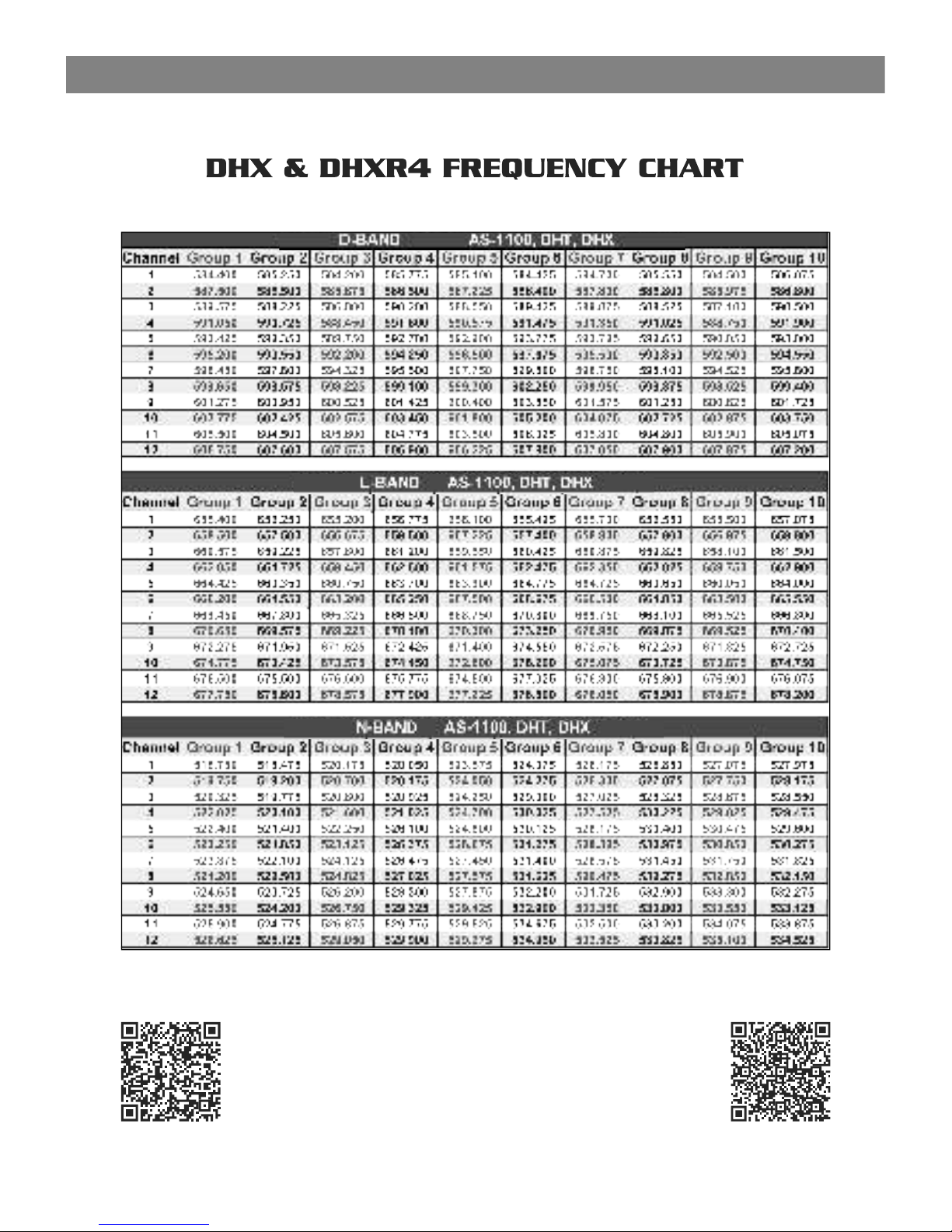
DHX & DHXR4
Frequency Chart
GALAXY AUDIO
Frequency Page
http://www.galaxyaudio.com/support/schematics-and-frequency-charts
Frequency Chart
Frequency Chart
Page 19

Please visit galaxyaudio.com for the latest updates
FCC Consumer Alert for Wireless Microphones (U.S.)
Most users do not need a license to operate this wireless microphone system.
Nevertheless, operating this microphone system without a lice nse is subject to certain
restrictions: the system may not cause harmful interference; it must operate at a low
power level (not in excess of 50 milliwatts); and it has no protection fr om interference
received from any other device. Purchasers should also be aware that the FCC is
currently evaluating use of wireless microphone systems, and th ese rules are subject to
change.
For more information, call the FCC at 1-888-CALL-FCC (TTY: 1-888-TELL-FCC) or visit
the FCC's wireless microphone website at www.fcc.gov/cgb/wir elessmicrophones
17
The frequencies of the Galaxy UHF Wireless Systems are on
frequencies that are used by Digital Television stations.
To be assured of the best performance, you should determine on
what RF channels the DTV stations in your area are broadcasting,
then set your wireless systems on frequencies that are not being
used.
You can find that information on this FCC web site.
https://www.fcc.gov/media/engineering/dtvmaps
Enter the zip code of the location where the wireless system will be
used into the location search bar. A list of stations in that area will be
listed. Click on the call sign of the stations and the details will
appear, showing you the RF channel the TV station is using.
Compare these with the chart to the left, and using the Galaxy
frequency charts on page 16, find a frequency that is not on an
active DTV RF channel.
For example, if you have an L-Band DHXR and your location has
DTV stations on RF channels 45 and 48, you will want to set your
DHXR on a frequency that is on RF channel 46 or 47.
DTV RF
Channel
Frequency
Range
14 470-476
15 476-482
16 482-488
17 488-494
18 494-500
19 500-506
20 506-512
21 512-518
22 518-524
23 524-530
24 530-536
25 536-542
26 542-548
27 548-554
28 554-560
29 560-566
30 566-572
31 572-578
32 578-584
33 584-590
34 590-596
35 596-602
36 602-608
37 608-614
38 614-620
39 620-626
40 626-632
41 632-638
42 638-644
43 644-650
44 650-656
45 656-662
46 662-668
47 668-674
48 674-680
49 680-686
50 686-692
51 692-698
DTV Frequency Ranges & FCC Consumer Alert
DTV Frequency Ranges & FCC Consumer Alert
Page 20
1-800-369-7768 www.galaxyaudio.com
V20170929
© Copyright Galaxy Audio 2017
WARRANTY Information can be viewed online at
http://www.galaxyaudio.com/support/warranty
THREE YEAR LIMITED WARRANTY
USER’S MANUAL
Specifications in this manual are subject to change without notice.
For the most up to date manual and information
visit www.galaxyaudio.com.
www.galaxyaudio.com/support/warranty
 Loading...