

Page 1
DHTRQUAD
U H F
USER'S MANUAL
WIRELESSMIC R O P H O N ES YSTEM
®
ANYSPOT
®
DHTRQUAD
UHF Four Channel
Diversity Wireless Receiver
IR
SYNC
POWER
®
MAKERS OF THE ORIGINAL
HOT SPOT PERSONAL MONITOR
Page 2

Contents
Contents
Sy ste m Co mpo nen ts. ... ... ... ... ... ........ ... ... ... ... ... ... 1
Ra ck-Mo untin g th e Re ceive r... .. ..... ..... ..... ..... .. ....2
HH 64/HH64 SC Hand hel d Tra nsm itt er... ... ... ... ... ..3
MB P64 Bo dypac k Tra nsmit ter. ..... ..... ..... ..... ... ..... 4
MB P76 Bo dypac k Tra nsmit ter. ..... ..... ..... ..... ... ..... 5
SM -W76 W irele ss Sho ckmount Base. ..... ..... .. ..... 6
Sy stem S etup. ..... ..... ..... ..... ..... .. ..... ..... ..... ..... ..... 7
Setting u p multiple re ce iv er s. .. .. ..........................8
Functions of the DHTRQUAD Rece iver...... ..........9
Troubl eshoo ting. ..... .. ..... ..... ..... ..... .. ..... ..... ..... ....1 0
Sp ecifi catio ns... ..... ..... ..... ..... ..... ..... ..... ..... ..... ... .11
Accessories and Replacement Parts.........................12
DHTRQUAD Frequency Chart....................................13
DHTRQUAD System
DHTRQUAD System
DHTRQUAD System
Thank you f or purchasin g the DHTRQ UA D wireless sy stem. For u se rs who ne ed an
advanced UHF wireles s system, the DHTRQUAD provides an e xc ellent sol ution.
With 120 selectab le channe ls , th e DH TR QUAD is perfect for appli ca tions such as
live shows, broadca st , me et ings, & musical instrum en ts . Touch buttons and liquid
crystal displ ay s al low for a qu ick and simple system set up . The "User Guide"a nd "
Quick Se tt ing Gu id e" inclu de d in yo ur syste m will pr ovide al l the d et ails you need t o
operate the s ys te m effic ie ntly.
Frequency Band
Most countr ie s closel y regula te the radio freque nc ies us ed in the t ransmissi on of
wi reles s in forma ti on. These r eg ula ti on s sta te which de vi ses c an u se whic h
frequenci es , a nd help to limit th e a mount of RF (r ad io frequency ) i nt erference in al l
wireless c ommunicatio ns . Th e DHTRQUAD offers 1 20 selectable cha nn els within
either the 58 4- 60 7MHz (Code D) o r 65 5-679MHz (Cod e L) f requency rang es .
To fa cilitate sys te m s etup and protect aga in st RF interferenc e, ea ch system comes
with multiple predefined frequency groups an d channe ls . When using a single
receiver/ tr an smitter, the oper at ing freq ue ncy will generally not ha ve to b e changed.
In an installatio n with multiple receivers/t ra nsmitters , each set must operat e on a
separate channe l from the o th ers. The group and channel syst em provides an
optimum fre qu en cy spread whe n us ing multiple re ce iver/tran sm it ter systems .
Page 3
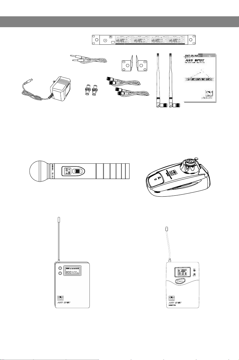
Al l systems in cl ude :
DHTRQ UAD Rec eiver
¼ " to ¼" Audi o Cable
P ower Su pply
Tw o Antenn as
Exten sion Ki t
Rack Ea rs
U ser Gui de
Transmitter Options:
INFRARED
INFRARED
CHANNEL
CHANNEL
OFF
OFF
BATT
BATT
HH64 / HH 64SC Ha ndhel d Mic/Tran smitt er
HH64 / HH 64SC Ha ndhel d Mic/Tran smitt er
System Components
System Components
System Components
System Components
®
ANYSPOT
®
DHTRQUAD
UHF Four Channel
Diversity Wireless Receiver
IR
SYNC
POWER
ON
ON
LAMP
POWER
BATT
GROUP CHANNEL
ASC
MBP64
MBP64
Body Pa ck
Tra nsmit ter
SM-W7 6 Wirel ess Sho ckmou nt Base
Visit our website
www.galaxyaudio.com
to see all of our great
headset & lavalier
options
MBP76
Body Pa ck
Tra nsmit ter
1
1
Page 4
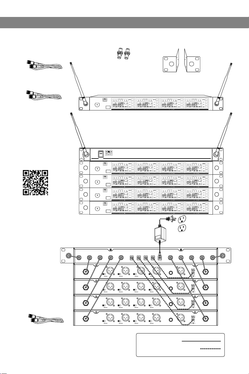
Rack-Mounting the Receiver
Rack-Mounting the Receiver
Rack-Mounting the Receiver
Rack-Mounting the Receiver
Rack -Mounting the Receiver
Maintai n a line of sig ht betw ee n
transmi tter an d an tenna .
Panel mount
Antenna
Extensi on
Cable
EXTBNC
BNC feed-through
®
®
ANYSPOT
ANYSPOT
®
®
DHTRQUAD
DHTRQUAD
UHF Four Channel
UHF Four Channel
Diversity Wireless Receiver
Diversity Wireless Receiver
IR
IR
SYNC
SYNC
POWER
POWER
connectors
CN-BNCPM
Rack Ears
MREDHTQ UAD
Shown with optional
ANT-DISTDC
antenna distributor.
ANT-DISTDC Info
Four DHTRQUAD receivers
The ANT-DISTDC will provide
DC power to operate up to
4 DHTRQUAD Receivers.
ANT-DISTDC
ANTENNA-B
®
ANYSP TO
®
POWER
®
ANYSPOT
®
DHTRQUAD
UHF Four Channel
Diversity Wireless Receiver
IR
SYNC
POWER
®
ANYSPOT
®
DHTRQUAD
UHF Four Channel
Diversity Wireless Receiver
IR
SYNC
POWER
®
ANYSPOT
®
DHTRQUAD
UHF Four Channel
Diversity Wireless Receiver
IR
SYNC
POWER
®
ANYSPOT
®
DHTRQUAD
UHF Four Channel
Diversity Wireless Receiver
IR
SYNC
POWER
DC IN
12~18
OUTPUT4
OUTPUT3
OUTPUT2
XLR balanced
XLR balanced
XLR balanced
XLR balanced
XLR balanced
XLR balanced
XLR balanced
XLR balanced
OUTPUT1
600mA
600mA
Channel 4
Channel 4
XLR balanced
XLR balanced
Channel 4
Channel 4
XLR balanced
XLR balanced
Channel 4
Channel 4
XLR balanced
XLR balanced
Channel 4
Channel 4
XLR balanced
XLR balanced
3000mA
600mA
600mA
Channel 1
Channel 1
XLR balanced
XLR balanced
Channel 1
Channel 1
XLR balanced
XLR balanced
Channel 1
Channel 1
XLR balanced
XLR balanced
Channel 1
Channel 1
XLR balanced
XLR balanced
ANT-1
ANT-2 ANT-3 ANT-4 ANT-5 ANT-6 ANT-7 ANT-8
M M M M
M M M M
H H H H
L L L L
H H H H
L L L L
Antenna-B Antenna-BChannel 4
Antenna-B Antenna-BChannel 4
Antenna-B Antenna-BChannel 4
Antenna-B Antenna-BChannel 4
Antenna-B Antenna-BChannel 4
Antenna-B Antenna-BChannel 4
Antenna-B Antenna-BChannel 4
Antenna-B Antenna-BChannel 4
Channel 4
Channel 4
SQL SQL SQL SQL
SQL SQL SQL SQL
XLR balanced
XLR balanced
M M M M
M M M M
H H H H
L L L L
H H H H
L L L L
Channel 4
Channel 4
SQL SQL SQL SQL
SQL SQL SQL SQL
XLR balanced
XLR balanced
M M M M
M M M M
H H H H
L L L L
H H H H
L L L L
Channel 4
Channel 4
SQL SQL SQL SQL
SQL SQL SQL SQL
XLR balanced
XLR balanced
M M M M
M M M M
H H H H
L L L L
H H H H
L L L L
Channel 4
Channel 4
SQL SQL SQL SQL
SQL SQL SQL SQL
XLR balanced
XLR balanced
Unbal output
Unbal output
Unbal output
Unbal output
Unbal output
Unbal output
Unbal output
Unbal output
ANT-DISTDC
UHF ANTENNA DIS TRIBU TOR
ANTENNA-A
8 in 1 Mix
4 in 1 Mix
8 in 1 Mix
4 in 1 Mix
XLR balanced
XLR balanced
8 in 1 Mix
4 in 1 Mix
8 in 1 Mix
4 in 1 Mix
XLR balanced
XLR balanced
8 in 1 Mix
4 in 1 Mix
8 in 1 Mix
4 in 1 Mix
XLR balanced
XLR balanced
8 in 1 Mix
4 in 1 Mix
8 in 1 Mix
4 in 1 Mix
XLR balanced
XLR balanced
Ten BNC connecting cables (included)
Two BNC connectors (included)
2
2
1. BNC Cables
2. Power Supply Cable
Page 5
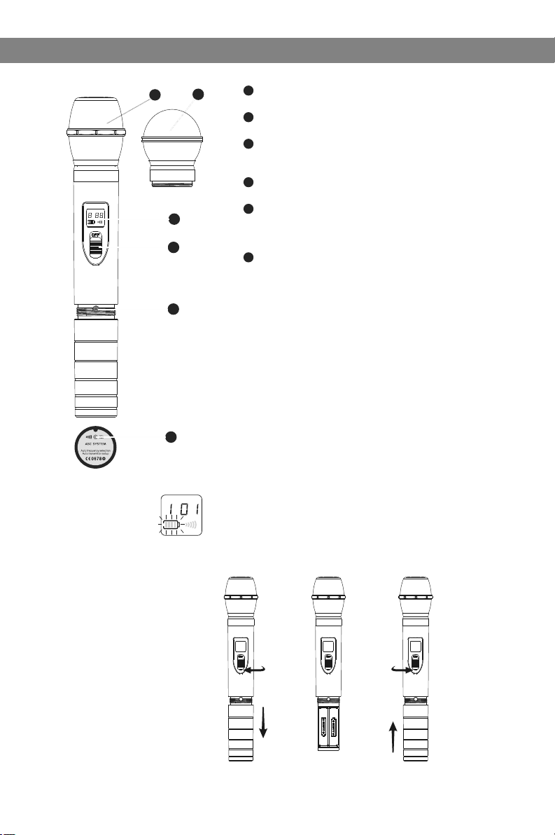
HH64/HH64SC Handheld Transmitter
HH64/HH64SC Handheld Transmitter
Functions:
1
1
2
Condensor mic
2
Dynamic mic
3
LCD screen
Please See “system setup ” on page 8.
4
Power Switch
GROUP CHANNEL
BATT
5
INFRARED
3
4
5
6
GROUP CHANNEL
INFRARED
BATT
Microphone Input Sensitivity Control.
Left turn for output level decrease, right
turn for output level increase.
6
IR Port receives infrared beam to synchronize frequencies.
Changing Batteries:
Batteries should be replaced when LCD indicator flashes.
Unscrew the battery cover as shown below. Install
two AA alkaline batteries, while observing correct polarity
indicators in the battery tray.
Expected life for two AA alkaline batteries is 8 hours.
3
Page 6

MBP64 Bodypack Transmitter
MBP64 Bodypack Transmitter
4
Functions:
1
Antenna.
2
Gain Switch.
There are three Gain settings on the MBP64. Select the
setting most suitable to your application.
Mic: Microphone Level
0: Guitar Level
-10dB: Line Level
3
Low Voltage/IR Transmission LED.
LED On: Battery Voltage OK.
LED Off: the Battery Voltage is Low.
Flashing LED: IR transmission is in progress
4
3-pin Input Jack.
5
Power/Backlight Control button
Press and Hold for Power On/Off.
Press and Release for Back-light On/Off.
6
ASC Frequency Synchronization Button.
Press this button to automatically set the Transmitter frequency
to match that of the Receiver. Use in conjunction with Receiver’s
ASC control.
7
LCD screen
BodyPack Transmitter
1
LAMP
5
6
8
POWER
ASC
-
+
3
2
T
T
A
B
7
+
-
See “system setup” on page 8.
8
IR Window Point this window towards IR window on Receiver during
ASC frequency synchronization.
10
9
- -
++
+ +
--
How to Wear the Bodypack Transmitter:
Slide the transmitter clip onto the belt or run a guitar strap
through the transmitter clip , as shown in the diagram at left.
10
9
Battery Replacement :
The life expectancy of two alkaline batteries is about six hours.
When the BATT indication symbol on the display screen is
flashing as shown in the diagram below, the batteries should be
replaced immediately, as shown in the diagram on the left.
BATT
Open
GROUP CHANNEL
Close
4
Page 7

MBP76 Bodypack Transmitter
MBP76 Bodypack Transmitter
Features
1
Antenna.
2
1
1
2
5
6
8
select
9
LCD p anel.
Please see (System Setup) on Page 7.
3
Pow er/AS C/ Low Ba ttery Indicator.
Constant Green: Power ON.
3
Flashing Green: IR ASC in progress, or Low Batteries.
4
4
Mut e Indic ator.
Constant Red: Audio Muted.
7
7
5
Pow er/Mu te Butt on.
Push and Hold for Power On/Off . Push on ce for Mu te On/Off.
6
IR Wi ndow.
Receives IR signals (ASC) to synchronize with Receiver.
7
Sel ect But ton.
Please see (System Setup) on Page 8.
8
3-p in Micr ophone Input Jack.
9
Gain Adjustment Switch.
Th ree gai n setti ngs are a vaila ble. Choose the
appropriate setting for your application:
Mic: Microphone
0dB: Guitar with passive pickups
-10dB: Guitar with active pickups, or Line Level Signals.
Note: To prevent accidental power or mute changes
during a performance, you may set the Lock function by
a simultaneous press and release of buttons 5 and 7. This
will disable all buttons and a “lock” icon will appe ar in the
LCD. Repeat procedure to return to normal operation.
10
Ope n
11
Clo se
Wearing the Backpa ck Tr an smitter:
Clip th e trans mitte r to a belt . For bes t resul ts, sli de the
trans mitte r down un til the b elt is pr es sed a ga ins t th e bas e
of the cl ip. Or, sl ide a gui tar str ap thro ug h the t ra nsm it ter
11
clip , as show n.
10
Changi ng b at teries:
Expec ted lif e for Two Alk aline b atter ies is ap proxi matel y 6 hours .
Repla ce batt eries w hen the G reen Po we r LED a nd t he LC D
Batte ry Indi cator ( shown b elow) b eg in to b li nk.
5
Page 8

SM-W76 Wireless Shockmount Base
SM-W76 Wireless Shockmount Base
1. Adjust the 16 position rotary knob on the rear of the SM-W76 base to change
the frequency. A small flat headed screwdriver can be used.
2. Use the chart to set up the DHTR/TRCR Group & Channel to the frequency
that corresponds to the SM-76 base.
3. Once the Group & Channel of the receiver is set, press the gray button on the
top of the SM-76 base to turn the microphone on.
6
Page 9

Rece iver Progr ammin g
System Setup
System Setup
GROUP CHANN EL
AUTO VOLUM E
CHANN EL CONTR OL
GROUP CHANN EL
AUTO VOLUM E
CHANN EL CONTR OL
GROUP CHANN EL
AUTO VOLUM E
CHANN EL CONTR OL
GROUP CHANN EL
AUTO VOLUM E
CHANN EL CONTR OL
GROUP CHANN EL
AUTO VOLUM E
CHANN EL CONTR OL
Handheld
Transmitter
MANUA L
GROUP
SELEC T
CHANN EL
SELEC T SELEC T
1
MANUA L
GROUP
SELEC T
CHANN EL
SELEC T SELEC T
2
MANUA L
GROUP
SELEC T
CHANN EL
SELEC T SELEC T
3
MANUA L
GROUP
SELEC T
CHANN EL
SELEC T SELEC T
4
MANUA L
GROUP
SELEC T
CHANN EL
SELEC T SELEC T
5
Bodypack
Transmitter
1
2
ANTEN NA
A
MHz
DISPL AY
FREQU ENCY
MASTE R
SELEC T LIST
ANTEN NA
A
MHz
DISPL AY
FREQU ENCY
MASTE R
SELEC T LIST
ANTEN NA
A
MHz
DISPL AY
FREQU ENCY
MASTE R
SELEC T LIST
ANTEN NA
A
MHz
DISPL AY
FREQU ENCY
MASTE R
SELEC T LIST
ANTEN NA
A
MHz
DISPL AY
FREQU ENCY
MASTE R
SELEC T LIST
Group and Channel Selection:
1
Press “SET” button twice, “GROUP SELECT” will display,
press or to choose the appropriate frequency group.
B
EXIT
2
Press “SET”again , “MANUAL CHANNEL SELECT” will display,
press or to choose the appropriate channel.
For best results when operating multiple systems, set all systems to
a single group, then set each system to a unique channel within that
group.
B
EXIT
Auto Frequency Finder function on the Receiver:
3
Choose “AUTO CHANNEL SELECT” by pressing “SET” once,
then press or . Receiver will automatically find a clear
frequency with no interference.
Receiver Volume Setting:
B
4
The receiver has an electronic volume control. Press or
EXIT
from the normal display (00 to 63)
Normal Display:
5
Frequency and Antenna A/B (RF Received).
B
EXIT
Transmitting frequency automatic setup:
Place the Transmitter “IR” window to face the Receiver “IR” window.
Then press the “ASC” button on the desired Receiver. The Transmitter
will automatically match the Receiver frequency.
B
Attention: The distance between the Receiver and Transmitter
EXIT
IR windows should be less than 0.5m during the ASC IR setup. When
setting up multiple Transmitters/Receivers, activate the ASC function
of only one Transmitter and Receiver at a time.
MBP76 Transmitter Status Display
Battery Status:
1
Battery Status Indicators for both the Handheld and Bodypack
Transmitters feature Four Level Displays.
Group and Channel Display:
2
After completing the ASC, both the Handheld and Bodypack
Transmitters will display the Group and Channel numbers selected.
Normal Display:
3
Both Handheld and Bodypack Transmitters will display Group and
Channel numbers as well as Battery Status.
3
7
Page 10
Setting up multiple receivers
Setting up multiple receivers
2
ANYSPOT
POWER
®
DHTRQUAD
UHF Four Channel
Diversity Wireless Receiver
IR
SYNC
®
4
5
11
1) Power on any pre-existing wireless systems and transmitters except the first DHT system.
2) Power on the first DHT Receiver.
3) The Control and set buttons are on the front of the receiver.
4) Press the set button until the group number flashes on the LCD screen
5) Press the up/down buttons to select group 1.
6Press the set button twice to get to the scan mode.
7) Press the up or down button. The unit will now go into scan mode. You will probably see the RF
meters light up if the scan sees other transmitters.
8) When it stops scanning, it will stop on the clearest frequency, and will be flashing the frequency
on the LCD screen.
9) Press the set button and it will set itself to that frequency. Do not wait to press the set button as
the DHT Receiver will revert back to the original frequency, and the process will need to be restarted
10) If the unit cannot find a good frequency within group 1, start the process again scanning
group 2, if that is also not clear try group 3, and so on till you get a good frequency.
When the DHT Receiver has been set to a clear frequency, use the ASC feature to sync the
receiver frequency to the transmitter.
11) Turn the transmitter on, aim the red infrared window on the transmitter towards the one on
the receiver and press the ASC button on the front of the receiver. The transmitter will sync to
the receivers frequency.
If you have more DHT systems to tune follow the same procedure on each one, always leaving
the previous system transmitter on.
8
Page 11

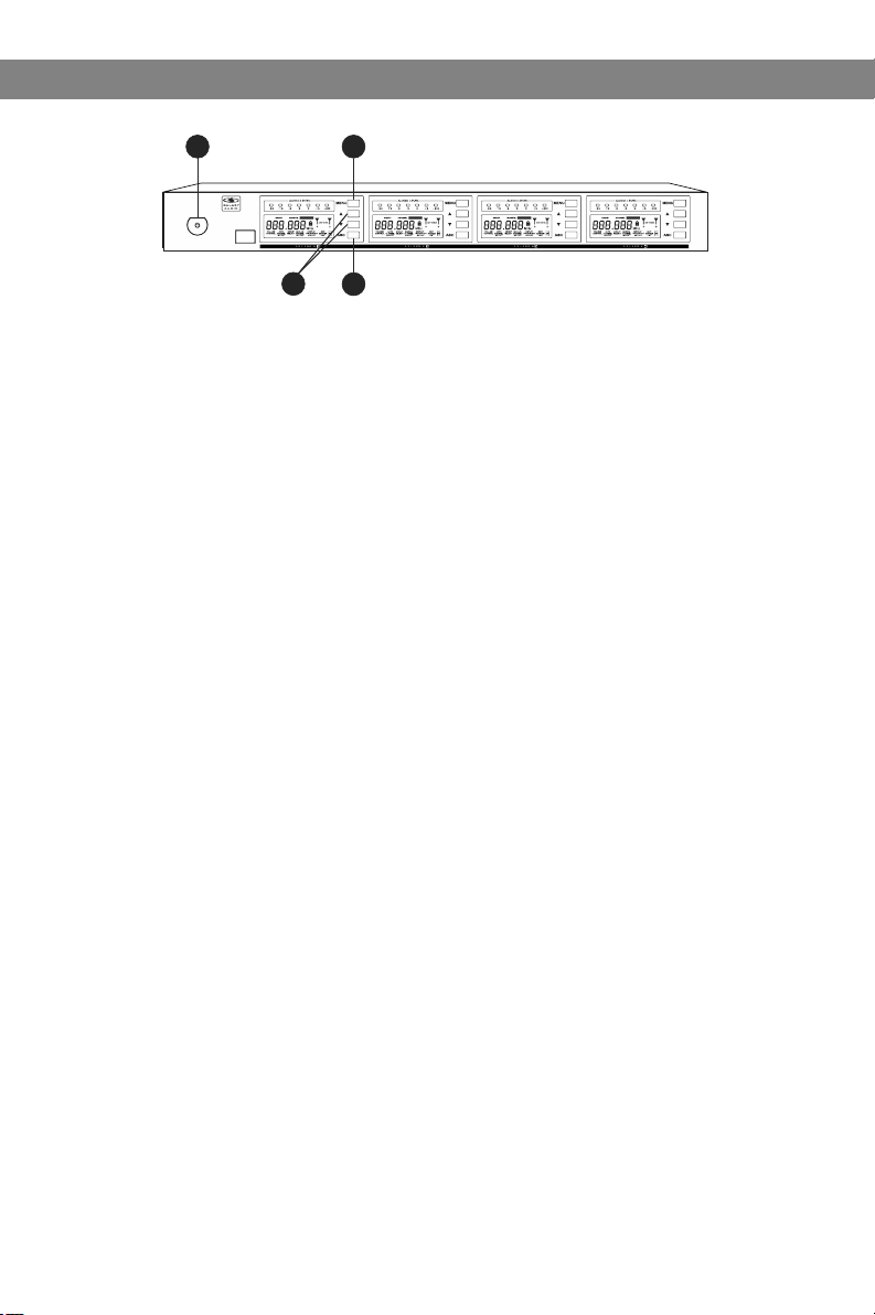
Functions of the DHTRQUAD Receiver
Functions of the DHTRQUAD Receiver
DHTRQUAD Receiver Featu res
Front Panel
®
ANYSPOT
POWER
DHTRQUAD
UHF Four Channel
Diversity Wireless Receiver
IR
SYNC
®
1
On/Of f Switc h
2
Infra re d (IR) Wi ndow
3
Audio L ev el Mete r
LCD Pan el
4
Syste m Se tup But ton
5
Pleas e se e “Syst em Setup” on P age 8
Syste m Me nu Up but ton
6
Pleas e se e “Syste m Setup” on Pa ge 8
ASC Syn c Bu tton
7
Press t o in itiat e IR connec tion be tw een
Recei ve r and Tran smitter.
Rear Pa ne l
M M M M
H H H H
L L L L
Antenna-B Antenna-BChannel 4
1
Anten na J ack B
2
Chann el 4 F ine Adju st ment of S quelc h Thres ho ld Leve l
Chann el 4 X LR Outp ut Jack
3
Chann el 3 F ine Adju st ment of S quelc h Thres ho ld Leve l
4
Chann el 3 X LR Outp ut Jack
5
Chann el 2 F ine Adju st ment of S quelc h Thres ho ld Leve l
6
7
Chann el 2 X LR Outp ut Jack
Channel 4
SQL SQL SQL SQL
XLR balanced
XLR balanced
Channel 4
XLR balanced
8
Syste m Me nu Down b utton
Pleas e se e “ Syste m Setup” on Pa ge 8
9
Anten na A Ind icato r
Light s wh en Anten na A is ac tive .
10
Anten na B I ndica tor
Light s wh en Anten na B is activ e .
Channel 1
XLR balanced
8 in 1 Mix
4 in 1 Mix
XLR balanced
Unbal output
Chann el 4 F ine Adju st ment of
8
Squel ch Thre sh old Lev el
9
Chann el 1 X LR Outp ut J ack
10
1/4in ch M ix Outp ut Jack
11
Balan ce d Mix Out put Jack
DC Powe r In put Jac k
12
Anten na j ack A
13
The 3 position Squelch Adjustment helps to prevent extraneous RF from being picked up and turned
into audio when the transmitter is off. The higher level will reduce the useable distance of the transmitter
from the receiver. Use the lowest setting to keep the receiver quiet when the transmitter is off.
9
Page 12

Troubleshooting
Troubleshooting
Tips for Improving Sys te m Performance
Maintain a line of sight between transmitters and anten nas.
Avoid p lacin g the receiver near metal surfaces or any digital equipment (CD players, computers, etc).
Keep the receiver away from the wall and at least 1m from the ground.
Cellular telephones and two-way radios can int erfer e with th e opera tion of w irele ss syst ems.
Do not use these devices in close proximity to the wireless system s.
Trouble sh oo ting
Issue I ndica tor Sta tus Sol ution
No soun d or fain t
sound .
Disto rtion o r
unwan ted noi se.
Disto rtion l evel
incre ases gr adual ly.
Sound l evel di ffere nt
from ca bled gu itar or
micro phone , or when
using d iff er ent gui tars.
Tra nsmit ter LCD o ff.
Recei ver LCD o ff. Make su re AC adap ter is se curel y
Recei ver ind icate s RF. Incre ase rec eiver v olume .
Recei ver ind icate s No RF,
Transm itter L CD is on.
The b at ter y po wer ind icato r
light o n LCD fla shes.
Recei ver Ind icate s RF.
Transm itter p ower in dicat or
light f lashi ng on the L CD.
Turn on tr ansmi tter.
Make su re the ba tteri es are in stall ed
corre ctly.
plugg ed into e lectr ical ou tlet an d in to
DC inpu t conne ctor on r ear pan el of
recei ver.
Make su re Gain a djust ment sw itch on
the tra nsmit ter is se t corre ctly (a pplie s
only to M BP76 Bo dypac k.)
Make su re Trans mitte r and Rec eiver
are set t o the sam e frequ ency.
Make su re Trans mitte r is in ran ge of
Recei ver.
Make su re no lar ge meta l objec ts are
near Tra nsmit ter or Re ceive r.
Chang e the bat terie s in tran smitt er.
Remov e nearb y sourc es of RF in ter feren ce (CD pl ayers , compu ters,
in-ea r monit or syst ems, et c.)
Repla ce Trans mitte r batte ries.
Adjust Tr ansmi tter Ga in and Re ceive r
Volume a s neces sary.
10
Page 13

Specifications
Specifications
System
Frequency Range: CODE D 584~607 MHz
CODE L 655~679 MHz
Transmitter Output level: 10 dBm
Band: UHF
Operating Range Under Typical
Conditions: 300'
Note: actual range depends on RF signal
absorption, reflection, interference, and
battery characteristics.
Audio Frequency Response (+/-3dB):
60Hz~16kHz
Total Harmonic Distortion (+/-30kHz deviation,
1KHz tone): <1%
Dynamic Range: >90dB A-weighted
Operating Temperature Range:
14ºF to 122ºF (-10º C to +50º C)
Bodypack Transmitter:
Max Audio Input Level:
0 dBV maximum at mic gain position.
+10 dBV maximum at 0 dB gain position.
+20 dBV maximum at 10 dB gain position.
Gain Adjustment Range: 30dB
Input Impedance: 470k
Dimensions: 3.5" x 2.6" x 1"
(89mm H x 65mm W x 24mm D)
Weight: 3.0oz (85 g) (without batteries)
Power Requirements:
2 “AA” alkaline or rechargeable Batteries
batteries
Battery Life:
About 6 hours
Handheld Transmitter:
Max Audio input level: 0dBV
Dimensions: 9.5" x 2.1" dia.
(242mm x 54mm dia.)
Weight: 10.6oz (300 g) (without batteries)
Power Requirements: 2 “AA” size
alkaline or rechargeable batteries
Battery Life: About 6 hours
Shockmount Transmitter:
Number of Channels: 16
Number of Simultaneous Systems:
4-8 across multiple bands
Carrier Frequency Bandwidth: Code D 584-607 MHz
Code L 655-679 MHz
Operating Range : 150'
Number of Inputs: 1
Type of Connections: XLRF
Indicators: Low battery LED
Frequency Response: 60Hz~16kHz
SNR: 102dB (a)
THD+N: <1%
RF Power: 10 mW
Phantom Power: 4VDC
Power Requirements: 2 “AA” size
alkaline or rechargeable batteries
Power Consumption: 110mA
Weight: 1.55 lbs (without batteries)
Receiver:
Audio Output Level (+/-30kHz deviation,
1kHz tone): XLR connector (into 600 load) -12dBV
¼" connector (into 3k load) -18dBV
Output Impedance: XLR connector 200
¼" connector 1k
XLR output: Impedance balanced
Pin1:Ground (cable shield)
Pin2:Audio
Pin3:No Audio
Sensitivity: -93dBm for 30dB
Image Rejection: >90dB
Dimensions: 1.7" x 8.3" x 6.3"
(44mm H x 212mm W x 160mm D)
Weight: 31.75oz (900 g)
Power Requirements:
12-18 V dc at 1000mA, supplied by external
power supply.
11
Page 14

Accessories and Replacement Parts
Accessories and Replacement Parts
Many of these parts and accessories may be found and purchased from the Galaxy Audio
website in either the Galaxy Store (www.galaxyaudio.com/store.php) or in the accessories
tab of each products web page.
AS-EXTBNC - BNC Connector and Cable for front mounting the
antennas on the DHTQUAD.
AS-ANTBNC - Replacement BNC Antenna for use with Galaxy Audio
Wireless Personal Monitors and Wireless Microphones.
WMC-CGR - DC Charger for AS-1500R, HH64, HH64SC, & MBP76.
Charges 2 body packs or handhelds at once.
MC-L - Wireless Microphone Clip
MC-SC - Spring Loaded Microphone Clip
AS-CLIP911R - Replacement Belt Clip for AS-900, AS-1100, MBP52,
& MBP64
AS-CLIP1576 - Replacement Belt Clip for AS-1500 & MBP76
12
AS-UA12-14.5 - Universal Power Supply for Replacement Power
Supply for AS-900, AS-1100, AS-1500, VES, VSC, ECD, ECM, PSE,
TRC, DHT, DHTQUAD, & CTS. Includes adapters for most other
countries.
PS-13.5-.35.5 - Replacement Power Supply for AS-900, AS-1100,
AS-1500, VES, VSC, ECD, ECM, PSE, TRC & DHT.
ANT-AMPMIC - Antenna Amplifier utilizes phantom power and a low
noise design which covers all UHF frequency points from 500mHz to
900mHz. Metal construction, requires phantom power (9VDC), 50
ohm input/output impedance.
ANT-PDL - Directional antenna used to decrease interference to
other equipment. Frequency range 500-900MHz The UHF wide-band
(500-900 MHZ) directional LPDA (log periodic dipole array) antenna
reduces outside interference while providing increased send/receive
signal range. Each antenna paddle is matched to 50 ohms
impedance with a low-loss BNC connector; 7dBi gain. For permanent
or temporary installation; mounts to 5/8"-27 threads.
Page 15

DHTRQUADFREQUENCYCHART
FCC Consume r Ale rt f or Wireless M ic rophones (U.S .)
Most users do n ot n ee d a license to op er ate this wirele ss m icrophone s ys te m.
Neverthel es s, o perating th is m icrophone sys te m without a lic en se i s subject to ce rt ain
restricti on s: the system may n ot c ause harmful in te rference; i t mu st operate at a low
power level ( no t in e xcess of 50 mil li watts); and it ha s no p rotection f ro m in terferenc e
received fr om a ny o ther device . Pu rchasers shou ld a lso be aware th at t he F CC is
currently e va lu ating use of wi re less micropho ne s ystems, and t he se r ules are subj ec t to
change.
For more info rm at ion, call the F CC a t 1-888-CALL- FC C (TTY: 1-888- TE LL -FCC) or visi t
the FCC's wir el es s microphon e we bsite at www.fcc .g ov/cgb/wi re le ssmicroph on es
Please v is it g al axyaudio.com for the latest updat es
13
Page 16

THREE YEAR LIMITED WARRANTY
WARRANTY Information can be viewed online at
http://www.galaxyaudio.com/warranty.php
DHTRQUAD
USER'S MANUAL
Specifications in this manual are subject to change without notice.
For the most up to date manual and information
visit www.galaxyaudio.com.
1-800-369-7768 www.galaxyaudio.com
© Copyright Galaxy Audio 2013
Printed in China
V09132013
 Loading...