

Page 1
Page 2

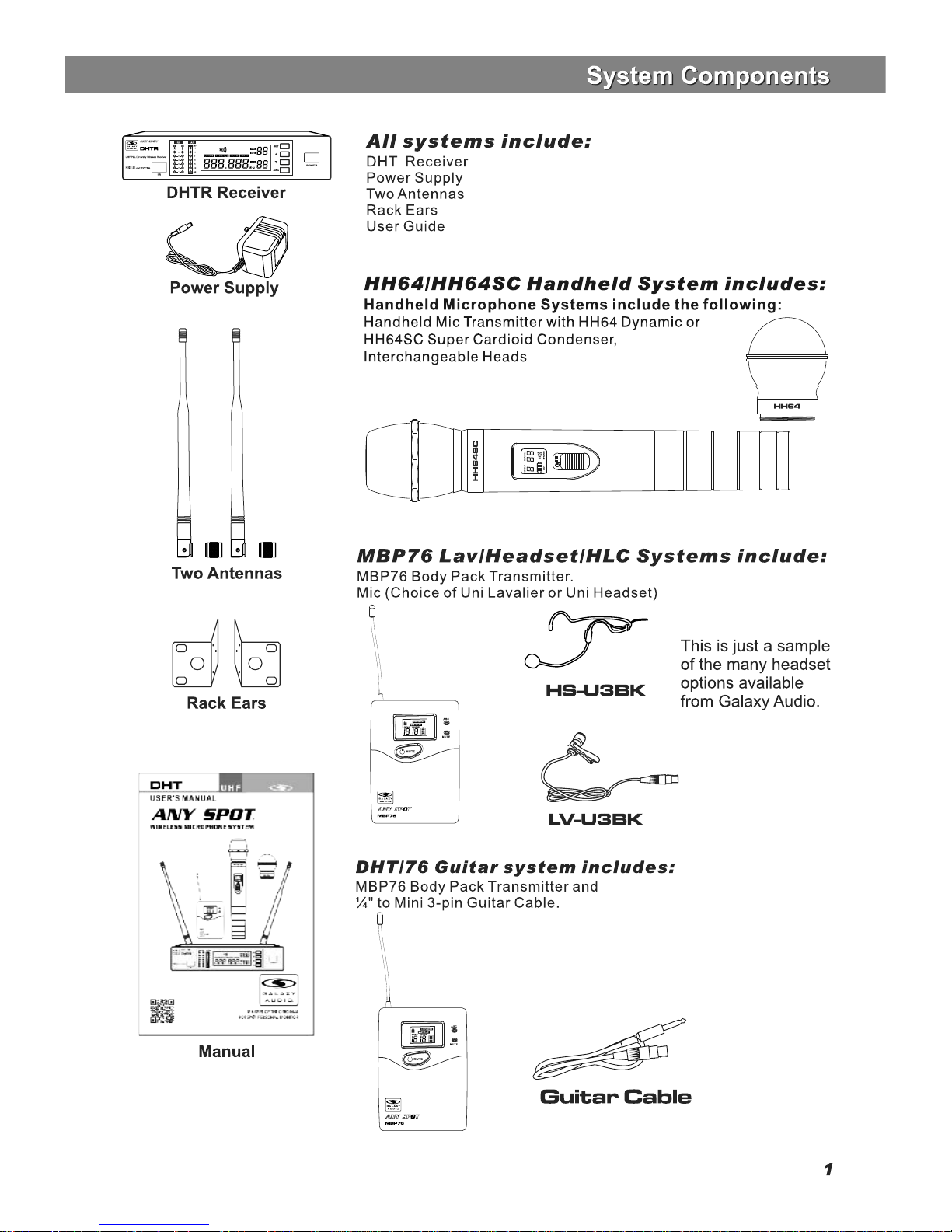
System Components.........................................1
DHT Receiver Features.....................................2
HH76 Handheld Transmitter...............................3
MBP76 Body Pack Transmitter...........................4
System Setup.....................................................5
Setting Up Multiple Receivers.............................6
Rack-Mounting the Receivers............................7
Troubleshooting..............................................8
Specifications....................................................9
Contents
Contents
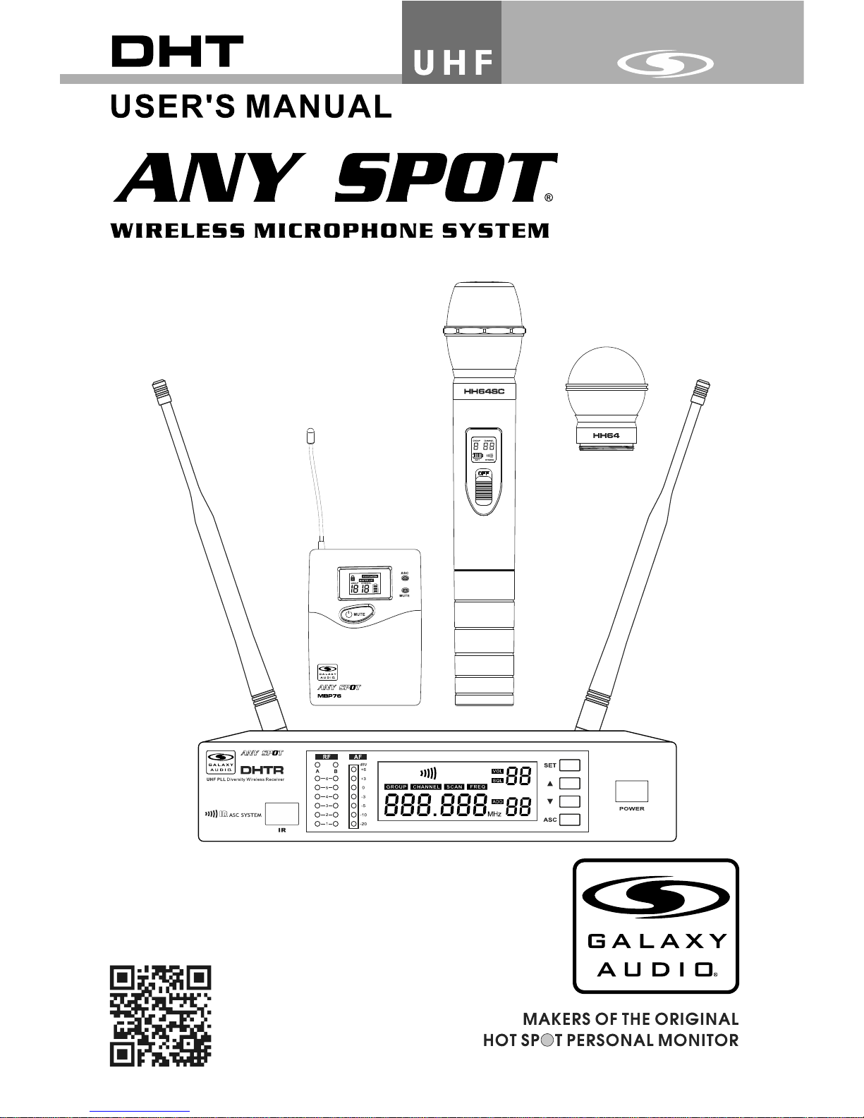
Introduction
Introduction
Thank you for choosing the Galaxy Audio DHT Wireless
Microphone System. You have joined hundreds of thousands of
other satisfied Galaxy customers. Since 1977 Galaxy Audio’s
professional experience in design and manufacturing ensure
our products quality, performance and reliability.
For the most up-to-date manual and information
visit www.galaxyaudio.com.
Frequency Band
Most count ries closely regulate the radio frequencies used in the transmission of
wireless information. These regulations state which devises can use which frequencies,
and help to limit the amount of RF ( radio frequ ency) interferenc e in all wireless
communications. The DHTRQUAD offers 120 selectable channels within either the 584607MHz (Code D) or 655-679MHz (Code L) frequency ranges.
To facilitate system setup and protect against RF interference, each system comes wit h
m u l t i p l e pr e d e f i n e d f r e q u e n c y gr o u p s an d ch a n n e l s . W h e n u s i n g a s i n g l e
receiver/transmitter, the operating fr equency will generally not have to be changed. In
an installation with mu ltiple receivers/tr ansmit ters, each set must operate on a separate
channel from the other s. The group and channel system provides an optimum frequency
spread when using multiple receiver/transmitter systems.
Page 3
Page 4
2
+
-
1 2 3 4 5 6
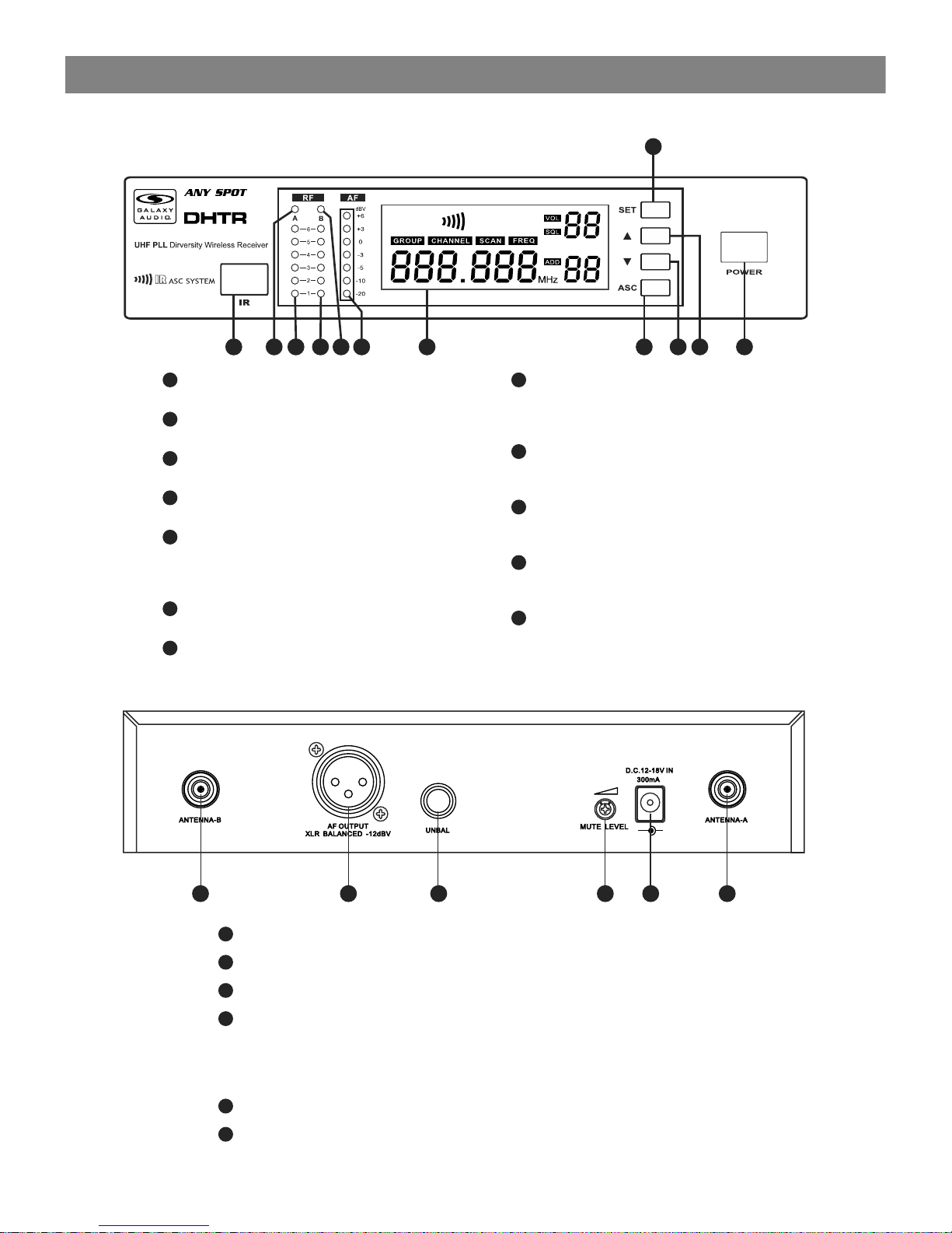
In frar ed (IR) Win dow.
Ant enna A ind icator li ght.
In dica tes when Ant enna A is ac tive .
Ant enna A RF st rength in dica tor.
Ant enna B R F strengt h indi cator.
Antenn a B indi cator lig ht.
Indic ates w hen Antenn a B is act ive.
Aud io Sig nal recei ved in dicator.
LC D Scre en.
See: Sy stem Setup on Pag e 8.
1
2
3
4
5
6
7
ASC S ync Bu tton.
Press t o initiate IR con nection betwe en
recei ver an d transmi tter.
Sy stem M enu Down Bu tton .
See: Sy stem Setup on Pag e 8.
Sy stem M enu Up Butt on.
See: Sy stem Setup on Pag e 8.
Sy stem S etup Butt on:
See: Sy stem Setup on Pag e 8.
On /Off Switch.
8
9
10
11
12
Antenna Jack B 50 ohm.
XLR Output Jack.
¼" Output Jack.
Mute Threshold Fine Adjustment.
This is set at the factory and usually does not need to be adjusted.
If interference signals are received, this threshold value may be increased
by turning the knob clockwise until the RF signal lamp goes out.
DC Power Input Connector.
Antenna Jack A 50 ohm
1
2
3
4
5
6
DHTR Receiver Features
Front Panel
Rear Panel
Functions of the DHTR Receiver
Functions of the DHTR Receiver
11
2 3 4 5 6 7 8
9
1 10
12
Page 5

3
CLOSE
OPEN
Super Cardioid with Condenser Element
Cardioid Dynamic Element
LCD screen
Please See “system setup ” on page 7.
Power Switch
Microphone Input Sensitivity Control.
Left turn for output level decrease, right
turn for output level increase.
IR port Receivers infrared beam to synchronize frequencies.
1
2
3
4
5
6
Functions:
1
2
3
4
5
6
Battery Replacement
Batteries should be replaced when LCD indicator flashes.
Unscrew the battery cover as shown below. Install
two AA alkaline batteries, while observing correct polarity
indicators in the battery tray.
Expected life for two AA alkaline batteries is about 8 hours.
HH64/HH64SC Handheld Transmitter
HH64/HH64SC Handheld Transmitter
Bottom of
Handheld
Page 6

select
Open
Clos e
1
1
2
2
3
3
4
4
5
5
6
6
7
7
8
8
9
9
2
1
Wearing the Back Pack Transmitter:
Clip th e tran smitter t o a belt . For best res ults, slide the
trans mitt er down unt il the b elt is pres sed ag ainst the b ase
of the cl ip. Or, s lide a guit ar str ap throug h the tr ansmitt er
clip ,a s show n.
Changing batteries:
Expec ted li fe for Two Alkalin e batteries is ap proximately 6 h ours.
Repla ce bat teries wh en the G reen Powe r LED an d the LCD
Batte ry Ind icator (s hown b elow) beg in to bl ink.
Features
Antenna.
LCD panel.
Please see (System Setup) on Page 8.
Power/ASC/ Low Battery Indicator.
Constant Green: Power ON.
Flashing Green: IR ASC in progress, or Low Batteries.
Mute Indicator.
Constant Red: Audio Muted.
Power/Mute Button.
Push and Hold for Power On/Off. Push once for Mute On/Off.
IR Window.
Receives IR signals (ASC) to synchronize with Receiver.
Select Button.
Please see (System Setup) on Page 8.
3-pin Microphone Input Jack.
Gain Adjustment Switch.
Three gain settings are available. Choose the
appropriate setting for your application:
Mic: Microphone
0dB: Guitar with passive pickups
-10dB: Guitar with active pickups, or Line Level Signals.
Note: To prevent accidental power or mute changes
during a performance, you may set the Lock function by
a simultaneous press and release of buttons 5 and 7. This
will disable all buttons and a “lock” icon will appear in the
LCD. Repeat procedure to return to normal operation.
MBP76 Body Pack Transmitter
MBP76 Body Pack Transmitter
4
2
1
Page 7

Group and Channel Selection: Press and Hold the SET button. The
Group number will flash. Press or to choose the appropriate frequency
group, as shown on the left ; press (SET) again , (CHANNEL) flashes,
press or to choose the appropriate channel, as shown on the left .
For best results when operating multiple systems, set all systems to a
single group: then set each system to a unique channel within that group.
Receiver Volume Setting:
The receiver has an electronic volume control. When in the normal display,
press or to control the output volume (64 steps total) as shown at
left.
Normal Display:
Volume and Frequency, as shown at left .
LED columns to the left of the LCD display show RF & AF Levels.
Automatic Transmitter Setup:
Once the desired channel is set on the Receiver, you may allow the
Transmitter channel to be set automatically. Note: only one Transmitter
may used with each Receiver.
Turn on the Transmitter. Position the Transmitter IR window directly in front
of the Receiver IR window. The IR window of the MBP76 Body Pack is
located under the battery door while the IR window of the HH64 Handheld
is located at the bottom end of the mic body. Press the ASC Button on the
Receiver. The ASC Icon will flash in the Receiver LCD. The RF Meters
will light when the synchronisation is complete. The Group and Channel
number of the Receiver should now be displayed in the Transmitter LCD.
With the HH64 turn on the transmitter after pressing the ASC button.
Note: The Transmitter must be within half a meter distance from
the Receiver during IR ASC automatic channel setting.
HH64 and MBP76 Transmitter Status Display
Battery Status:
Battery Status Indicators for both the Handheld and Body Pack
Transmitters feature Four Level Displays as shown in .
Group and Channel Display:
After completing the ASC, both the Handheld and Body Pack Transmitters
will display the Group and Channel numbers selected as shown in .
Normal Display:
Both Handheld and Body Pack Transmitters will display Group and
Channel numbers as well as Battery Status as shown in .
Handheld
Transmitter
Body Pack
Transmitter
GRO UP CHAN NEL
SCA N
FRE Q
GRO UP CHAN NEL
SCA N
FRE Q
GRO UP CHAN NEL
SCA N
FRE Q
GRO UP CHAN NEL
SCA N
FRE Q
GRO UP CHAN NEL
SCA N
FRE Q
GRO UP CHAN NEL
SCA N
FRE Q
1
2
3
4
5
1
1
2
2
3
3
4
5
Recei ver Pr ogra mming
System Setup
System Setup
1
2
3
5
Page 8

11
5
4
Setting up multiple receivers
Setting up multiple receivers
1) Power on any pre-existing wireless systems and transmitters except the first DHT system.
2) Power on the first DHT Receiver.
3) The Control and set buttons are on the front of the receiver.
4) Press the set button until the group number flashes on the LCD screen
5) Press the up/down buttons to select group 1.
6Press the set button twice to get to the scan mode.
7) Press the up or down button. The unit will now go into scan mode. You will probably see the RF
meters light up if the scan sees other transmitters.
8) When it stops scanning, it will stop on the clearest frequency, and will be flashing the frequency
on the LCD screen.
9) Press the set button and it will set itself to that frequency. Do not wait to press the set button as
the DHT Receiver will revert back to the original frequency, and the process will need to be restarted
10) If the unit cannot find a good frequency within group 1, start the process again scanning
group 2, if that is also not clear try group 3, and so on till you get a good frequency.
When the DHT Receiver has been set to a clear frequency, use the ASC feature to sync the
receiver frequency to the transmitter.
11) Turn the transmitter on, aim the red infrared window on the transmitter towards the one on
the receiver and press the ASC button on the front of the receiver. The transmitter will sync to
the receivers frequency.
If you have more DHT systems to tune follow the same procedure on each one, always leaving
the previous system transmitter on.
2
6
Using the auto scan function to find clear frequencies for your DHT System
Page 9

Inclu ded Single Rack E ars
BNC CONNECTOR & CABLE:
For front mounting antenna to rack ears.
Part# AS-EXT50/BNC (optional)
Rack Sh elf fo r mountin g
Two Rec eive rs side by si de
MRTD/ P/T (optional )
Rack-Mounting the Receiver
Rack Mounting
Rack Mounting
7
Page 10

Issue I ndicato r Stat us So luti on
Troubleshooting
Transmi tter LCD off.
Turn on tr ansm itter.
Make su re the b atterie s are in stalled
corre ctly.
Recei ver LC D off. Make su re AC ada pter is sec urel y
plugg ed int o electri cal ou tlet and in to
DC inpu t conn ector on re ar pan el of
recei ver.
Recei ver in dicates R F. Incre ase re ceiver vo lume .
Make su re Gai n adjustm ent sw itch on
the tra nsmi tter is set c orrectly (app lies
only to M BP76 B ody Pack. )
Recei ver in dicates N o RF,
Transm itte r LCD is on.
Make su re Tran smitter a nd Rec eiver
are set t o the same freque ncy.
Make su re Tran smitter i s in ran ge of
Recei ver.
Make su re no la rge metal o bjec ts are
near Tra nsmi tter or Rec eive r.
The batter y power indicat or
light o n LCD fl ashes.
Chang e the ba tteries i n tran smitter.
Disto rtio n or
unwan ted no ise.
Recei ver In dicates R F.
Remov e near by source s of RF in ter feren ce (CD p layers, c ompu ters,
in-ea r moni tor syste ms, etc.)
Disto rtio n level
incre ases g raduall y.
Sound l evel d ifferent
from ca bled g uitar or
micro phon e, or when
using d iff erent guitars .
Adjust Tr ansm itter Gai n and Re ceiver
Volume a s nece ssary.
Transm itte r power ind icat or
light f lash ing on the LC D.
Repla ce Tran smitter b atte ries.
Maintain a line of sight between transmitters and antennas.
Avoid placing the receiver near metal surfaces or any digital equipment (CD players, computers, etc).
Keep the receiver away from the wall and at least 1m from the ground.
Cellular telephones and two-way radios can interfere with the operation of wireless systems.
Do not use these devices in close proximity to the wireless systems.
Tips for Improving System Performance
No soun d or fai nt
sound .
Troubleshooting
Troubleshooting
8
Page 11

Specifications
Specifications
System
Frequency Range: CODE D 584~607 MHz
CODE L 655~679MHz
Transmitter Output level: 10 dBm
Band: UHF
Operating Range Under Typical Conditions: 300'
Note: actual range depends on RF signal
absorption, reflection, and interference.
Audio Frequency Response: (+/-3dB)
60Hz~16KHz
Total Harmonic Distortion (+/-30KHz deviation,
1KHz tone): <1%
Dynamic Range: >90dB A-weighted
Operating Temperature Range:
14ºF to 122ºF (-10º C to +50º C)
Note: battery characteristics may limit
this range:
Body Pack Transmitter:
Max Audio Input Level:
0 dBV maximum at mic gain position.
+10 dBV maximum at 0 dB gain position.
+20 dBV maximum at 10 dB gain position.
Gain Adjustment Range: 30dB
Input Impedance: 470K ohms
Dimensions: 3.5" x 2.6" x 1"
(89mm H x 65mm W x 24mm D)
Weight: 3.0oz (85 g) (without batteries)
Power Requirements:
2 “AA” alkaline or rechargeable Batteries
batteries
Battery Life:
About 6 hours
Receiver:
Audio Output Level: (+/-30KHz deviation, 1KHz tone)
XLR connector (into 600 ohms load) -12dBV
¼" connector (into 3K ohms load) -18dBV
Output Impedance: XLR connector 200Ohms
¼" connector 1K ohms
XLR output: Impedance balanced
Pin1:Ground (cable shield)
Pin2:Audio
Pin3:No Audio
Sensitivity: -93dBm for 30dB
Image Rejection: >90dB
Dimensions: 1.7" x 8.3" x 6.3"
(44mm H x 212mm W x 160mm D)
Weight: 31.75oz (900 g)
Power Requirements:
12-18 V dc at 400mA, supplied by external
power supply.
Handheld Transmitter:
Max Audio input level: 0dBV
Dimensions: 9.5" x 2.1" dia.
(242mm x 54mm dia.)
Weight: 10.6oz (300 g) (without batteries)
Power Requirements: 2 “AA” size
alkaline or rechargeable batteries
Battery Life: About 6 hours
9
Page 12

1-800-369-7768 www.galaxyaudio.com
V20140625
Printed in China
© Copyright Galaxy Audio 2014
WARRANTY Information can be viewed online at
http://www.galaxyaudio.com/warranty.php
Specifications in this manual are subject to change without notice.
For the most up to date manual and information
visit www.galaxyaudio.com.
 Loading...