

Page 1
Page 2

Contents
Contents
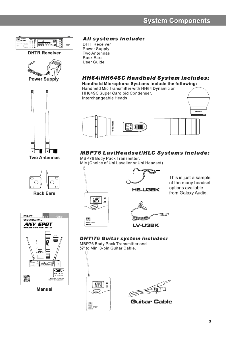
System Components.........................................1
DHT Receiver Features.....................................2
HH76 Handheld Transmitter...............................3
MBP76 Body Pack Transmitter...........................4
System Setup.....................................................5
Setting Up Multiple Receivers.............................6
Rack-Mounting the Receivers............................7
Troubleshooting .. .. .. .. .. .. .. .. .. .. .. ........................8
Specifications....................................................9
Introduction
Introduction
Thank you for choosing the Galaxy Audio DHT Wireless
Microphone System. You have joined hundreds of thousands of
other satisfied Galaxy customers. Since 1977 Galaxy Audio’s
professional experience in design and manufacturing ensure
our products quality, performance and reliability.
For the most up-to-date manual and information
visit www.galaxyaudio.com.
Frequency Band
Most countri es closely regulat e the rad io f requenc ie s used in the tr ansmiss io n of
wire le ss inf or mation. Th es e regu la tions st ate wh ic h devise s can u se which frequen ci es,
and help to li mi t th e am ount of RF (radio fre qu ency) inter fe rence in all wire le ss
comm un ication s. The DH TR QUAD o ff er s 12 0 select ab le c ha nnels wi thin e ither the 58 4607M Hz ( Code D) or 65 5- 679MHz (C od e L) freque nc y ranges.
To fa cilitat e syst em setup and protect again st RF interf er ence, ea ch s ys tem co mes wi th
m u l t i p l e p r e d e f i n e d f r e q u e n c y g r o u p s a n d c h a nn e l s . W h e n u s i n g a s i n g l e
rece iv er/tran sm itter, t he oper at ing fre qu ency wi ll gene ra lly n ot have t o be ch an ged. In
an in st allatio n w ith mu lt iple rec ei vers/tr an smitters, each set mu st opera te on a se pa rate
chan ne l from th e o thers. The gr ou p and chann el system p ro vides an op timum fr eq uency
spre ad w hen using m ul tiple rec ei ver/tra ns mitter sy st ems.
Page 3
Page 4
Functions of the DHTR Receiver
Functions of the DHTR Receiver
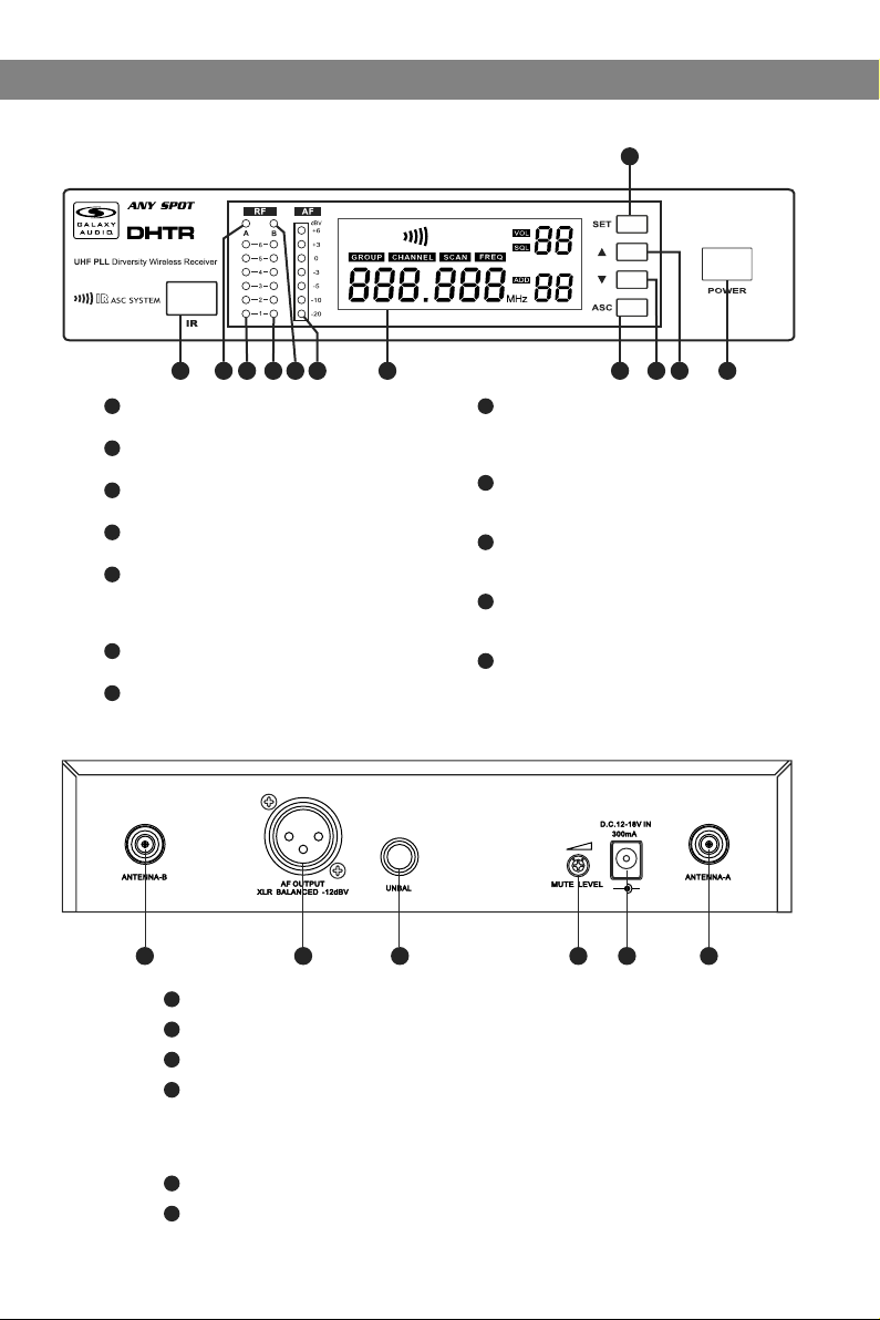
DHTR Recei ver Features
Fron t Panel
2 3 4 5 6 7 8
1 10
1
Infrared ( IR ) Wi nd ow.
2
Antenna A in di ca to r li gh t.
3
Indicate s wh en An te nn a A is act iv e .
4
Antenna A RF s tr en gt h in di ca tor.
5
Antenna B RF st re ng th i nd ic at or.
Antenna B indicato r li gh t.
Indicates when Ant en na B i s ac ti ve .
6
Audio Signal re ce iv ed i nd ic at or.
7
LCD Screen .
See: System Setup o n Pa ge 8 .
Rear P anel
11
12
9
8
ASC Sync Butt on .
Press to initiate I R co nn ec ti on b et we en
receiver and tran sm it te r.
9
System Men u Do wn B ut to n.
See: System Setup o n Pa ge 8 .
10
System Men u Up B ut to n.
See: System Setup o n Pa ge 8 .
11
System Set up B ut to n:
See: System Setup o n Pa ge 8 .
12
On/Off S wi tc h.
-
+
1 2 3 4 5 6
1
Antenna Jack B 50 ohm.
2
XLR Output Jack.
3
¼" Output Jack.
4
Mute Threshold Fine Adjustment.
This is set at the factory and usually does not need to be adjusted.
If interference signals are received, this threshold value may be increased
by turning the knob clockwise until the RF signal lamp goes out.
5
DC Power Input Connector.
6
Antenna Jack A 50 ohm
2
Page 5

HH64/HH64SC Handheld Transmitter
HH64/HH64SC Handheld Transmitter
Functions:
1
1
2
3
4
5
6
Super Cardioid with Condenser Element
2
Cardioid Dynamic Element
3
LCD screen
Please See “system setup ” on page 7.
4
Power Switch
5
Microphone Input Sensitivity Control.
Left turn for output level decrease, right
turn for output level increase.
6
IR port Receivers infrared beam to synchronize frequencies.
Bottom of
Handheld
Battery Replacement
Batteries should be replaced when LCD indicator flashes.
Unscrew the battery cover as shown below. Install
two AA alkaline batteries, while observing correct polarity
indicators in the battery tray.
Expected life for two AA alkaline batteries is about 8 hours.
OPEN
CLOSE
3
Page 6

MBP76 Body Pack Transmitter
MBP76 Body Pack Transmitter
Features
1
Antenna.
2
1
2
5
6
8
select
9
LCD panel.
Pleas e see (S ystem Setup) on Page 8.
3
Power/ASC/ Low Battery Indicato r.
Const ant Gr een: Power ON.
3
Flash ing Gr een: IR ASC in progress, or Low Batteries.
4
Mute Indicator.
4
Constant Red: Audio Muted.
5
Power/Mute Button.
7
Push and Hold for Power On/Off. Push once for Mute On/ Off.
6
IR Window.
Recei ves IR s ignals (ASC) to synchronize with Receiver.
7
Select Button.
Please see (System Setup) on Page 8.
8
3-pin Microphone Input Jack.
Gain Adjustment Switch.
9
Three gain settings are av aila ble. Choose the
appro pria te setting for your application:
Mic: Mi crop hone
0dB: Gu itar w ith passive pickups
-10dB : Guit ar with active pickups, or Line Level Signa ls.
Note: To prevent accidental power or mute c hang es
during a performance, you may set the L ock fu nction by
a simultaneous press and release of butto ns 5 and 7. This
will disable all buttons and a “lock” icon wi ll appear in the
LCD. Repeat procedure to return to no rmal o peration.
2
Wearing the B ack Pack Transmi tter:
Clip the transmit te r to a b el t . Fo r be st r es ul ts, slide the
1
transmitter dow n un ti l th e be lt i s pr es se d ag ainst the base
of the clip. Or, slide a g ui ta r st ra p th ro ug h th e tr ansmitter
2
clip ,as shown.
1
Changin g batterie s:
Expected life for Tw o Alk al in e ba tteries is approxim at el y 6 ho ur s.
Replace batteri es w he n th e Gr ee n Po we r LE D an d the LCD
Ope n
Clo se
4
Battery Indicat or ( sh ow n be lo w) b eg in t o bl ink.
Page 7

GROU P CH ANNEL
GROU P CH ANNEL
GROU P CH ANNEL
GROU P CH ANNEL
GROU P CH ANNEL
GROU P CH ANNEL
SCAN
SCAN
SCAN
SCAN
SCAN
SCAN
System Setup
System Setup
Recei ve r Progr a mmin g
FREQ
1
FREQ
2
FREQ
3
FREQ
FREQ
4
FREQ
Group and Channel Selection: Press and Hold the SET button. The
Group number will flash. Press or to choose the appropriate frequency
group, as shown on the left ; press (SET) again , (CHANNEL) flashes,
press or to choose the appropriate channel, as shown on the left .
1
2
For best results when operating multiple systems, set all systems to a
single group: then set each system to a unique channel within that group.
Receiver Volume Setting:
The receiver has an electronic volume control. When in the normal display,
press or to control the output volume (64 steps total) as shown at
3
left.
Normal Display:
Volume and Frequency, as shown at left .
LED columns to the left of the LCD display show RF & AF Levels.
4
Automatic Transmitter Setup:
Once the desired channel is set on the Receiver, you may allow the
Transmitter channel to be set automatically. Note: only one Transmitter
may used with each Receiver.
Turn on the Transmitter. Position the Transmitter IR window directly in front
of the Receiver IR window. The IR window of the MBP76 Body Pack is
located under the battery door while the IR window of the HH64 Handheld
is located at the bottom end of the mic body. Press the ASC Button on the
Receiver. The ASC Icon will flash in the Receiver LCD. The RF Meters
will light when the synchronisation is complete. The Group and Channel
number of the Receiver should now be displayed in the Transmitter LCD.
With the HH64 turn on the transmitter after pressing the ASC button.
5
Note: The Transmitter must be within half a meter distance from
the Receiver during IR ASC automatic channel setting.
Handheld
Transmitter
5
Body Pack
Transmitter
1
2
3
HH64 and MBP76 Transmitter Status Display
Battery Status:
Battery Status Indicators for both the Handheld and Body Pack
Transmitters feature Four Level Displays as shown in .
Group and Channel Display:
After completing the ASC, both the Handheld and Body Pack Transmitters
will display the Group and Channel numbers selected as shown in .
Normal Display:
Both Handheld and Body Pack Transmitters will display Group and
Channel numbers as well as Battery Status as shown in .
1
2
3
5
Page 8

Setting up multiple receivers
Setting up multiple receivers
Using the auto scan function to find clear frequencies for your DHT System
4
5
1) Power on any pre-existing wireless systems and transmitters except the first DHT system.
2) Power on the first DHT Receiver.
3) The Control and set buttons are on the front of the receiver.
4) Press the set button until the group number flashes on the LCD screen
5) Press the up/down buttons to select group 1.
6Press the set button twice to get to the scan mode.
7) Press the up or down button. The unit will now go into scan mode. You will probably see the RF
meters light up if the scan sees other transmitters.
8) When it stops scanning, it will stop on the clearest frequency, and will be flashing the frequency
on the LCD screen.
9) Press the set button and it will set itself to that frequency. Do not wait to press the set button as
the DHT Receiver will revert back to the original frequency, and the process will need to be restarted
10) If the unit cannot find a good frequency within group 1, start the process again scanning
group 2, if that is also not clear try group 3, and so on till you get a good frequency.
When the DHT Receiver has been set to a clear frequency, use the ASC feature to sync the
receiver frequency to the transmitter.
11) Turn the transmitter on, aim the red infrared window on the transmitter towards the one on
the receiver and press the ASC button on the front of the receiver. The transmitter will sync to
the receivers frequency.
If you have more DHT systems to tune follow the same procedure on each one, always leaving
the previous system transmitter on.
11
2
6
Page 9
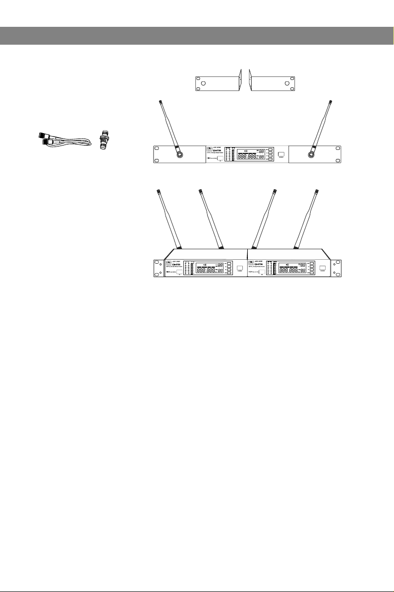
Rack-Mo unting the R eceiver
BNC CONNECTOR & CABLE:
For front mounting antenna to rack ears.
Part# AS-EXT50/BNC (optional)
Rack Shelf for moun ti ng
Two Re ce iv er s si de b y si de
MRTD/P/T (optio na l)
Rack Mounting
Rack Mounting
Included Single R ac k Ea rs
7
Page 10

Troubleshooting
Troubleshooting
Tips for Impr oving Syst em Pe rformanc e
Maintain a line of sight between tran smit ters and antennas.
Avoid p laci ng the receiver near metal surfaces or any di gita l equipment (CD players, computers, etc).
Keep the receiver away from the wall an d at lea st 1m from the ground.
Cellular telephones and two-way radio s can interfere with the operation of wireless sy stem s.
Do not use these devices in close proxi mity t o the wireless systems.
Troubles hooting
Issue Indicat or S ta tu s So lu ti on
No sound or faint
sound.
Distortion or
unwanted noise.
Distortion leve l
increases gradu al ly.
Sound level diffe re nt
from cabled guita r or
microphone, or wh en
using diffe re nt g ui ta rs .
Tra ns mi tt er LCD off.
Receiver LCD off. Make sure AC adapter i s se cu re ly
Receiver indica te s RF. Increase receiv er v ol um e.
Receiver indica te s No R F,
Transmitter LCD is o n.
The b at te ry p ow er i nd ic at or
light on LCD flashe s.
Receiver Indica te s RF.
Transmitter powe r in di ca to r
light flashing on t he L CD .
Turn on transmitte r.
Make sure the batte ri es a re i ns ta ll ed
correctly.
plugged into elec tr ic al o ut le t an d in to
DC input connecto r on r ea r pa ne l of
receiver.
Make sure Gain adju st me nt s wi tc h on
the transmitter i s se t co rr ec tl y (a pp li es
only to MBP76 Body Pa ck .)
Make sure Transmit te r an d Re ce iv er
are set to the same fre qu en cy.
Make sure Transmit te r is i n ra ng e of
Receiver.
Make sure no large me ta l ob je ct s ar e
near Transmitter o r Re ce iv er.
Change the batter ie s in t ra ns mi tt er.
Remove nearby sou rc es o f RF i nt er ference (CD playe rs , co mp ut er s,
in-ear monitor sy st em s, e tc .)
Replace Transmit te r ba tt er ie s.
Adjust Transmitte r Ga in a nd R ec ei ve r
Volume as necessar y.
8
Page 11

Specifications
Specifications
System
Frequency Range: CODE D 584~607 MHz
CODE L 655~679MHz
Transmitter Output level: 10 dBm
Band: UHF
Operating Range Under Typical Conditions: 300'
Note: actual range depends on RF signal
absorption, reflection, and interference.
Audio Frequency Response: (+/-3dB)
60Hz~16KHz
Total Harmonic Distortion (+/-30KHz deviation,
1KHz tone): <1%
Dynamic Range: >90dB A-weighted
Operating Temperature Range:
14ºF to 122ºF (-10º C to +50º C)
Note: battery characteristics may limit
this range:
Receiver:
Audio Output Level: (+/-30KHz deviation, 1KHz tone)
XLR connector (into 600 ohms load) -12dBV
¼" connector (into 3K ohms load) -18dBV
Output Impedance: XLR connector 200Ohms
¼" connector 1K ohms
XLR output: Impedance balanced
Pin1:Ground (cable shield)
Pin2:Audio
Pin3:No Audio
Sensitivity: -93dBm for 30dB
Image Rejection: >90dB
Dimensions: 1.7" x 8.3" x 6.3"
(44mm H x 212mm W x 160mm D)
Weight: 31.75oz (900 g)
Power Requirements:
12-18 V dc at 400mA, supplied by external
power supply.
Body Pack Transmitter:
Max Audio Input Level:
0 dBV maximum at mic gain position.
+10 dBV maximum at 0 dB gain position.
+20 dBV maximum at 10 dB gain position.
Gain Adjustment Range: 30dB
Input Impedance: 470K ohms
Dimensions: 3.5" x 2.6" x 1"
(89mm H x 65mm W x 24mm D)
Weight: 3.0oz (85 g) (without batteries)
Power Requirements:
2 “AA” alkaline or rechargeable Batteries
batteries
Battery Life:
About 6 hours
Handheld Transmitter:
Max Audio input level: 0dBV
Dimensions: 9.5" x 2.1" dia.
(242mm x 54mm dia.)
Weight: 10.6oz (300 g) (without batteries)
Power Requirements: 2 “AA” size
alkaline or rechargeable batteries
Battery Life: About 6 hours
9
Page 12

WARRANTY Information can be viewed online at
http://www.galaxyaudio.com/warranty.php
Specifications in this manual are subject to change without notice.
For the most up to date manual and information
visit www.galaxyaudio.com.
1-800-369-7768 www.galaxyaudio.com
© Copyright Galaxy Audio 2014
Printed in China
V20140625
 Loading...