

Page 1
CTS
U H F
USER'S MANUAL
®
Page 2

Contents
Contents
Introduction..................................................................................................1
System Components.....................................................................................2
Functions of the CTSR Receiver.................................................................3-4
Connecting a Receiver to the RF Distributor...................................................5
System Setup............................................................................................6-8
HH85 Handheld Transmitter..........................................................................9
MBP85 Body Pack..................................................................................10-11
Main Functions Description of Transmitters..................................................12
Handheld and Body Pack Transmitter.....................................................13-14
Troubleshooting..........................................................................................15
Specifications.............................................................................................16
Page 3

Introduction
Introduction
Thank you for choosing the Galaxy Audio CTS Wireless
Microphone System. You have joined hundreds of thousands of
other satisfied Galaxy customers. Since 1977 Galaxy Audio’s
professional experience in design and manufacturing ensure
our products quality, performance and reliability.
For the most up to date manual and information
visit www.galaxyaudio.com.
1
Page 4
CTS System Components
CTS System Components
System Overview
The CTS system is specifically designed for a variety of performance art. The
CTS system has 18 different groups, and each group consists of 14
compatible receiving channels. The CTS system is capable of searching
vacant channels automatically, and synchronizing with transmitter accurately.
The CTS system consists of a receiver, transmitter, and power adaptor. The
transmitter can either be a handheld or a belt pack (choice of headset or
lavaliere mic). Systems also include a ¼" signal cable, (2) AA batteries and a
user manual.
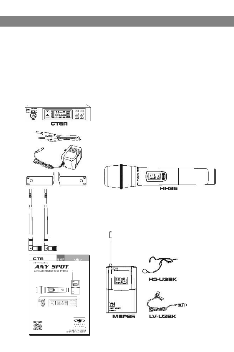
All CTS systems include the following components:
CTS Receiver
One ¼" Audio Cable
Power Adapter
Two Antennas
Single Rack Ears
User Manual
Handheld Microphone Systems include the following:
HH85 Handheld Transmitter
Lavalier/Headset Microphone systems include the
following:
MBP85 Bodypack Transmitter
Microphone (choice of Lavalier, or Headset)
2
Page 5
CTSR Receiver Featur es
Front Panel
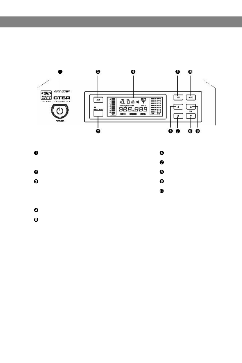
Functions of the CTSR Receiver
Functions of the CTSR Receiver
Power Switch.
With red light indicator, press it one second to turn it
on or off.
IR Port
IR Sync Signal Button: Pressing button starts 10 second
transmitter synchronization indicated by flashing Icon.
During the 10 seconds aim the transmitter IR port at the
receiver IR port and the transmitter will sync to the
receiver frequency.
LCD Display Panel
System setting button
System Menu up button
System Menu down button
SQL decrease button
SQL increase button
Automatically Search
for vacant channels
3
Page 6
Functions of the CTSR Receiver
Functions of the CTSR Receiver
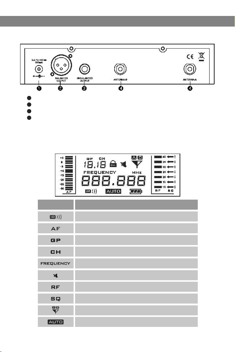
Rear Panel
1
DC power socket
2
Balanced audio output socket
3
Un-balanced audio output socket: 1/4 inch
4
Antenna Socket
Receiver LCD Functions
Display
Function
IR port
Audio Level
Current Group Number
Current Channel Number
Current Frequency
Mute, it will disappear when the mic is on
Receiving Signal Status
Squelch Level Setting
Antenna A B status
Automatically Search for vacant channels
4
Page 7

Connecting Receiver to the RF Distributor
Connecting Receiver to the RF Distributor
Connecting Receiver to the RF Distributor
Rack mount side panel
Balanced output cable
DC power adapter
1/4 inch Output cable
5
Page 8
System Setup
System Setup
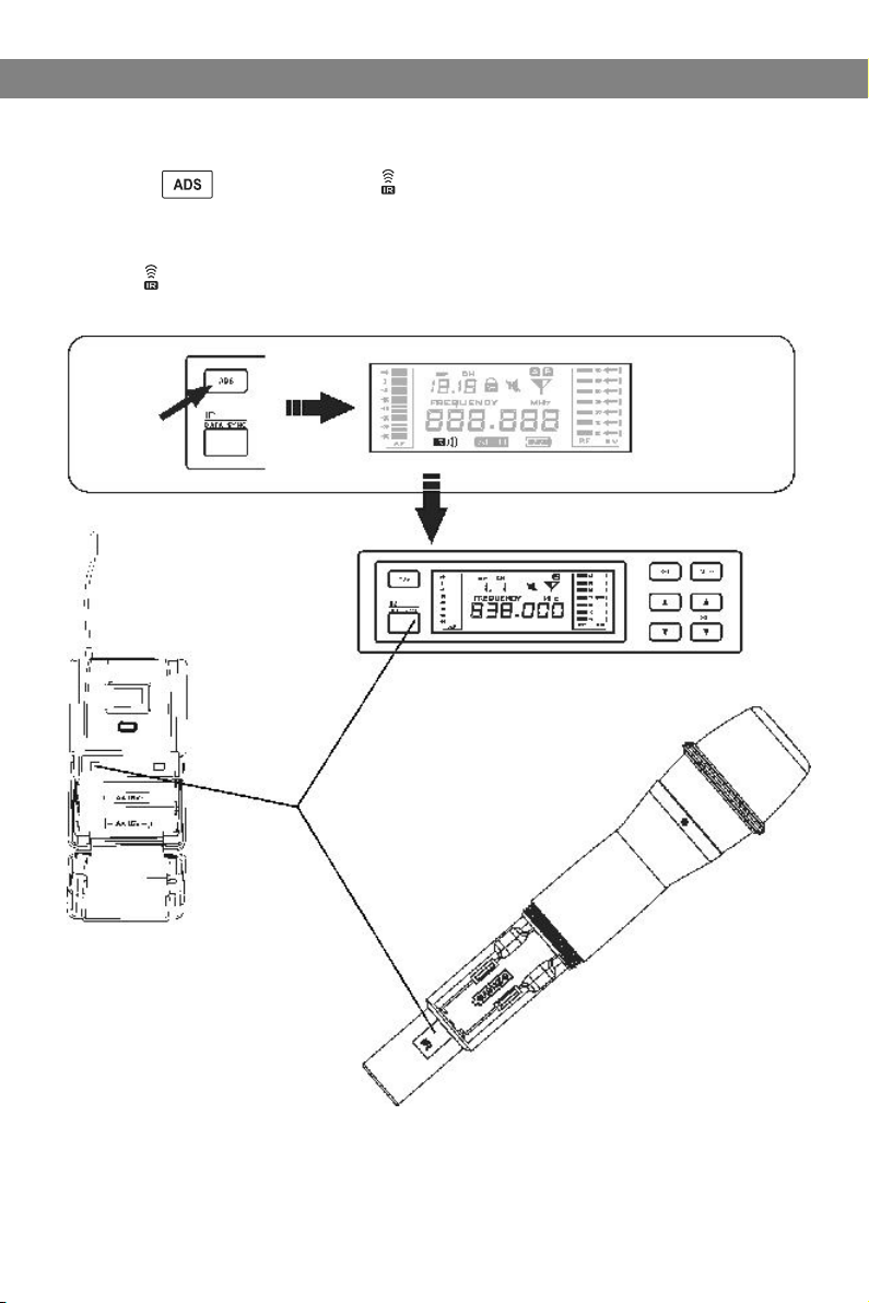
1. IR SYCN Setting
Press the button, the icon will flash for 10 seconds. During the 10
seconds aim the transmitter IR port at the receiver IR port and the
transmitter will sync to the receiver frequency. When the sync is complete
the icon will disappear and the display will return to its normal state.
6
Page 9
System Setup
System Setup
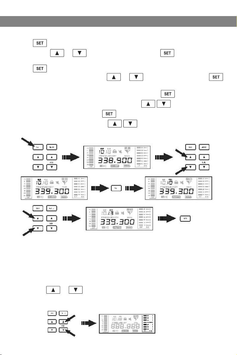
2. Selecting Frequency
Press button,the GP flashes to indicate the group can be chosen by
pressing the or button,to confirm press the button.It will
return back to the original state without any operation within 5 seconds.
Press to confirm the group selection, the CH flashes to indicate the
channel can be chosen, press the or button to choose, Press
again to exit setting mode automatically after confirmation.
When choosing frequencies from the “U” group, press button, and the
top three numbers before the point flash, press buttons to choose,
1MHz for every push, and press again to confirm, then the last three
number after the point blink, press buttons to choose, every step
for 25Khz.
3. SQ Setting and Change
The CTSR receiver has a build-in adjustable SQL(Squelch Level) function
which silences the output when the receiver does not get a strong or quality
signal from the transmitter, instead of reproducing noise. When squelch is
adjusted, the threshold of the signal quality or level is adjusted.
Press SQL or to change the value. The higher value means the
lower reception sensitivity and stronger anti-interference ability. The selection
should be based on the use of different locations to achieve the best effect.
7
Page 10
System Setup
System Setup
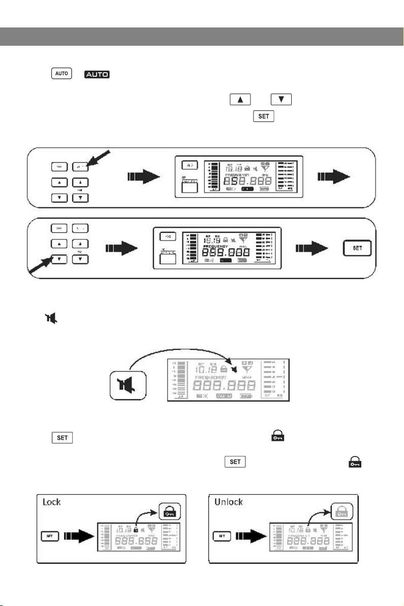
4. Automatically Search for Vacant Channel
Press , icon will start to flash ,then available channels will be shown
on the LCD display. For example , the LCD display shows 15, that means there are 15
vacant channels available. Then Press the button and to select an
appropriate channel. Once a channel is selected, press to confirm the setting.
If no vacant channel can be found within 5 seconds, receiver will automatically
return to the original state.
5. Auto Muting
The icon is displayed in the receiver LCD screen when the
frequency is different between receiver and transmitter or the receiver
can't receive any signal from the transmitter.
6. Locking and Unlocking
Press and hold for one second until LCD shows " ". At this time,
all buttons except Power/Mute will be disabled. All receiver’s setting
functions are now locked. To unlock, press and hold it until the “ “
icon disappears,the receiver is now unlocked.
8
Page 11

HH85 Handheld Transmitter
HH85 Handheld Transmitter
Functions:
1
Microphone Grille
2
LCD Display
3
Power and Mute switch:
hold for three seconds
to power on or off. Click
once to mute or unmute
output signal
4
System setting button.
5
System selection button.
6
Battery holder.
7
IR port: Receiving the IR
signal to SYNC the CTSR
receiver.
Changing Batteries:
Unscrew cover to access the Battery Tray. Observe
correct polarity markings when installing Batteries.
Loosen Tighten
8 Hrs +
5 to 6 Hrs
2 to 3 Hrs
Low Battery
9
Page 12

MBP85 Bodypack Transmitter
MBP85 Bodypack Transmitter
Functions:
1
Mini XRL input socket
2
Power/Mute switch: Press it and hold for
three seconds can power on or off. Click
once can mute or unmute output signal
3
Antenna
4
Low battery indicator
5
Mute indicator
6
LCD Display
7
IR port: Receiving the IR signal to SYNC
the CTSR receiver
8
System setting button
9
System Up or Down buttons
10
Battery holder
10
Battery Replacement:
Fold open the Battery Door as shown. Install Batteries
while observing correct polarity markings.
The life expectancy of two alkaline batteries is about 8 hours.
8 Hrs +
5 to 6 Hrs
2 to 3 Hrs
Low Battery
Page 13

MBP85 Bodypack Transmitter
MBP85 Bodypack Transmitter
How to Wear the MBP85 Transmitter:
Clip the transmitter to belt , or slide a guitar strap
through the transmitter's clip , as shown in the diagram at left.
For best results, slide the transmitter until the belt is pressed
against the base of the clip .
Microphones for bodypack transmitter
HS-U3BK Headset Microphone
Polar Patten: Unidirectional
Sensitivity: -65dB ± 2dB
Frequency Response:
50Hz-18KHz
Output impedance: <2K Ω
S/N Ratio: <38dB
LV-U3BK Clip-on Microphone
Polar Patten: Unidirectional
Sensitivity: -64dB ± 2.2dB
Frequency Response:
100Hz-20KHz
Output impedance:2K Ω
S/N Ratio: >44dB
1
2
1
This is just a sample of the
many headset options available
from Galaxy Audio.
11
Page 14

Main Functions Description of Transmitters
Main Functions Description of Transmitters
12
Display
Function
Transmitter Output Power
Battery Status
Current Frequency
Mute Symbol
Transmitter Output Level
Current Group Number
Current Channel Number
Function Locked Indicator
Page 15

Handheld and Bodypack Transmitter
Handheld and Bodypack Transmitter
Transmitter gain adjust:
Press , symbol flashing, press the button to change the relative level
in dB. (-9dB, -6dB, -3dB, 0dB, 3dB) then press the button again to confirm
it or press on Mute button to exit the setting.
Transmitter RF Power adjust:
Press twice, the signal icon flashes, press the button to change the
relative output level in mW. (5mW, 10mW, 20mW) then press again to confirm
it or press on Mute button to exit the setting.
Mute setting:
Press once, the transmitter will be muted right away and the icon displayed,
press one more time to unmute it.
* Button on handheld microphone has an identical function as the button
on bodypack transmitter.
13
Page 16

Handheld and Bodypack Transmitter
Handheld and Bodypack Transmitter
Current Frequency Checking:
Press button to show the current frequency, press to return.
If no operation was performed within 5 seconds, the display will return back to
normal display automatically.
Battery Status Indicator:
When the battery is low, the display shows an empty flashing battery icon .
The battery status of transmitter and receiver is synchronized.
When the battery is lower than 1.6V, an empty battery icon and Lo will appear
on the display for about three seconds, then an internal control circuit will
force the transmitter into off state automatically.
We recommend users change to a pair of new batteries when the battery icon
shows as 30%.
Lock and Unlock Setting:
Press button and hold it until LCD shows “ ”. At this time, all buttons except
Power on/off will be disabled. All transmitter's functions are now locked.
Press and buttons continuously back and forth (as shown below) three times
to unlock.
14
Page 17

Troubleshooting
Troubleshooting
Tips for Improvi ng S ystem Performance
Maintain a line of sig ht betw een transmitter and antenna.
Avoid p lacing the receiver near metal surfaces or any digital eq uipment (CD players, computers, etc).
Keep the receiver aw ay from t he wall and over 1m to the ground.
Cellular telepho nes, tw o-way radios and other RF transmitters can interfere wi th the tr ansmitting
frequencies, mai ntain a d istance from interfering equipment.
Trouble shooting
Issue I ndica to r Sta tu s Sol ut ion
No soun d or fain t
sound .
Disto rt ion o r
unwan te d noi se
burst s.
Disto rt ion l ev el
incre as es gr ad ually.
Sound l ev el di ffere nt
from ca bl ed gu it ar or
micro ph one , or w hen
using d iffer ent gui tars.
Tra nsmit ter ON In dicat or
stop fl as hin g
Power i nd ica to r off Make su re AC a dap te r is secu rely
Recei ve r RF in di cator g lows Tur n the rec eiver u p
Recei ve r RF in di cator o ff,
trans mi tte r in dicat or ON
Transm itter l ow b atter y
indic ator ON
Recei ve r RF in di cator O N
Transm itter l ow b atter y
indic at or ON
Tur n on tran smitt er.
Make su re t he +/ - in dicat or on bat tery
match t he tran sm itter t ermin als
plugg ed i nto e le ctric al outl et and in to
DC inpu t co nne ct or on rea r panel o f
recei ve r.
Tur n up the Ga in adju st men t sw itch in
the tra ns mit te r
Check t he p owe r co nnect ion of th e
recei ve r and a mp lifie r or mixe r
Take the re ce ive r aw ay from t he meta l
objec ts
Check w he the r th ere are o bstru ction s
betwe en r ece iv er and tr ansmi tter
Move th e trans mi tter ne ar the re ceive r
Check t he r ece iv er and tr ansmi tter
wheth er u se th e sa me freq uency
Chang e th e bat te ries in t ransm itter.
Remov e ne arb y so urces o f RF inte rferen ce ( CD pl ay ers, co mpute rs,
in-ea r mo nit or s ystem s, etc. )
Repla ce Tr ans mi tter ba tteri es.
Adjus t Tra nsm it ter Gai n and Rec eiver
Volume a s ne ces sa ry.
15
Page 18

Specifications
Specifications
CTSR System:
Available Channels: 920 Selectable Frequencies
(18 groups of 14 channels)
Band: UHF Frequency
Operating Range Under Typical Conditions: 300'
Audio Frequency Response: 60Hz - 16KHz
Note: battery characteristics may limit
this range.
Receiver:
CTSR
Frequency Range: CODE D 584~607 MHZ
CODE L 655~679 MHZ
Channels: 920 Selectable Frequencies
(18 groups of 14 channels)
Power Requirements: 12Vdc, 500mA
Bandwidth: 24 MHz
Sensitivity: -102 dBm
Signal-to-noise ratio: >105 dB(A)
Frequency Response: 60 Hz - 15 Khz
Output Level: 8 dBu Max
Output Connections: Balanced XLR,
Unbalanced 1/4"
IR Sync transmitter with receiver
Dimensions: 8.34" W x 6.29" D x 1.73" H
(212mm x 160mm x 44mm)
Weight: 1.98 lbs (900g)
Handheld Transmitter:
HH85
Polar Pattern: Cardioid
Element Type: Dynamic
LCD Display: Frequency, Battery Life,
Mute, Gain, RF Power, Lock
Selectable Power: 5, 10, 20mW
Selectable Gain: -3, 0, 3, 6, 9
Power Requirements: 2 “AA” Batteries alkaline
or rechargeable batteries
Battery Life: About 8 Hrs dependent on power setting
Dimensions: 9.68" x 2.08" (246mm H x 53mm W)
Weight: 8.8oz (250g)
Bodypack Transmitter:
MBP85
Frequency Range: CODE D 584~607 MHZ
CODE L 655~679 MHZ
LCD Display: Frequency, Battery Life,
Mute, Gain, RF Power, Lock
Selectable Power: 5, 10, 20mW
Selectable Gain: -3, 0, 3, 6, 9
Power Requirements: 2 “AA” size alkaline or
rechargeable batteries
Battery Life: About 8 Hrs dependent on power setting
Dimensions: 3.85" W x 2.51" H x 0.90" D
(98mm x 64mm x 23mm)
Weight: 3.17oz. (90g)
16
Page 19

Page 20

THREE Y E AR LIMITED W A RRANTY
WARRANTY Information can be viewed online at
http://www.galaxyaudio.com/warranty.php
CTS
USER'S MANUAL
Specifications in this manual are subject to change without notice.
For the most up to date manual and information
visit www.galaxyaudio.com.
1-800-369-7768 www.galaxyaudio.com
© Copyright Galaxy Audio 2012
V09112012
 Loading...