

Page 1

GALAXY AUDIO
®
®
CORE X250
CORE XP250
1999 Galaxy Audio, Inc.
OWNER’S MANUAL
©
Page 2
WARNING! TO PREVENT THE RISK OF FIRE OR ELECTRIC SHOCK, DO NOT EXPOSE THIS APPLIANCE
TO RAIN OR MOISTURE. TO PREVENT THE RISK OF ELECTRICAL SHOCK, DO NOT REMOVE COVER. NO
USER SERVICEABLE PARTS INSIDE. REFER SERVICING TO QUALIFIED SERVICE PERSONNEL.
This symbol indicates that a dangerous voltage constituting a risk of electric shock is present within this unit.
This symbol indicates that there are important operating and maintenance instructions in the literature
accompanying this unit.
GENERAL GUIDELINES FOR OPERATING THE CORE X250/XP250
DO NOT . . .
! Expose the CORE X250/XP250 to rain or moisture.
! Plug-in or unplug patch cords while the power is on.
! Plug-in or unplug an external speaker while the power is on. Doing so may cause a temporary short which can
result in damage to the amplifier section.
! Attempt to make any repairs to the CORE X250/XP250.
DO . . .
! Handle with care.
! Read this manual.
! Complete the registration card.
Page 3

TABLE OF CONTENTS
TYPICAL SETUP----------------------------------------------------------------------------------------------------- 2
CORE X250 FRONT PANEL-------------------------------------------------------------------------------------- 4
CORE XP250 FRONT PANEL------------------------------------------------------------------------------------ 5
CORE X250/XP250 REAR PANEL------------------------------------------------------------------------------ 6
SOUND REINFORCEMENT BASICS -------------------------------------------------------------------------- 7
Avoiding Feedback -------------------------------------------------------------------------------------------- 7
Monitor Placement --------------------------------------------------------------------------------------------- 7
Low Frequency Distortion----------------------------------------------------------------------------------- 7
Maximizing Gain ------------------------------------------------------------------------------------------------ 8
Ohm’s Law-------------------------------------------------------------------------------------------------------- 9
CORE X250 SPECIFICATIONS---------------------------------------------------------------------------------- 10
CORE XP250 SPECIFICATIONS-------------------------------------------------------------------------------- 11
ARCHITECT AND ENGINEER SPECIFICATIONS --------------------------------------------------------- 12
WARRANTY ----------------------------------------------------------------------------------------------------------- 12
BLOCK DIAGRAM--------------------------------------------------------------------------------------------------- 13
1
Page 4
®
CORE X250
TYPICTYPIC
TYPIC
TYPICTYPIC
AL SETUPAL SETUP
AL SETUP
AL SETUPAL SETUP
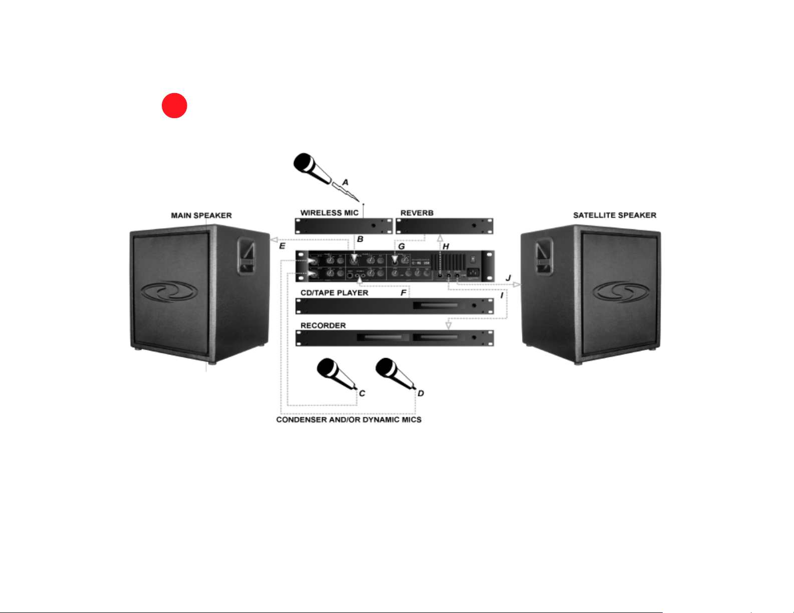
Virtually any combination of mics, instruments, or tape/CD players may be simultaneously plugged into the inputs for all channels with
the exception of the ¼” and RCA jacks for Channel 4. Since Channel 4’s ¼” and RCA jacks are parallel, simultaneously using both will
result in diminished sound quality.
2
Page 5

! Explanations of controls and jacks are preceded by boxes.
A
WIRELESS MIC
B
WIRELESS MIC RECEIVER OUTPUT to CORE X250 MIC (XLR) INPUT: Channel 1, and/or 2, and/or 3
! MIC IN (+24VDC phantom power) connects a microphone or other device which uses an XLR plug. Use
ONLY balanced devices and cables.
! LEVEL controls the amount (volume) of the channel’s signal that is sent to the MASTER mix.
! AUX controls the amount (volume) of the channel’s signal that is sent to the AUX mix. This control is
level
, meaning the AUX control is active only when the LEVEL control is turned up.
C/D
CONDENSER OR DYNAMIC MIC to CORE X250 MIC INPUT: Channel 1, and/or 2, and/or 3
! See
E
CORE X250 SPEAKER OUTPUT (REAR PANEL) to MAIN SPEAKER INPUT
! REAR PANEL (¼”) SPEAKER OUTPUT This
mix to the main speaker.
F
TAPE/CD PLAYER OUTPUT to CORE X250 (¼”) LINE INPUT or TAPE (RCA) INPUT: Channel 4
! BALANCED (¼”) LINE IN connects OUTPUT from an instrument.
! CD/TAPE (RCA) INPUT connects OUTPUT from a tape or CD player.
! LEVEL and AUX controls function as in B, C and D.
B
speaker level
(powered) output sends the
The ¼” and RCA jacks are parallel. If both are used, sound quality is diminished.
G
CORE X250 AUX OUTPUT to OUTBOARD PROCESSOR (reverb or similar device) INPUT
! AUX OUTPUT The
available at this ¼”
pre-master, pre-EQ
line level
(unpowered) output
AUX mix (determined by the channels’ AUX control settings) is
post-EQ
post-
master
H
OUTBOARD PROCESSOR (reverb or similar device) OUTPUT to CORE X250 AUX RETURN INPUT
! AUX RETURN (AUX IN) BALANCED (¼”) LINE INPUT accepts the
outboard processor. This input’s LEVEL control determines the amount of the “wet” (processed) signal that is
added to the MASTER mix.
I
CORE X250 LINE OUTPUT to RECORDER INPUT
! LINE OUTPUT provides a
identical to the powered mixes available from either the front or rear SPEAKER OUTPUT jacks.
J
CORE X250 SPEAKER OUTPUT (FRONT PANEL) to SATELLITE SPEAKER INPUT
! FRONT PANEL (¼”) SPEAKER OUTPUT provides a powered
MASTER mix to an unpowered satellite speaker; identical in content to the
at the rear (¼”) speaker output jack and the
line level
(unpowered)
line level
post-master, post-EQ
(unpowered) mix available at the (¼”) LINE output jack.
3
line level
(unpowered) signal from an
version of the MASTER mix;
post-master, post-EQ
speaker level
version of the
(powered) mix available
Page 6

®
CORE X250
CHANNEL 1 MIC (XLR) INPUT
CHANNEL 1 LEVEL
CHANNEL 1 AUX SEND
CHANNEL 2 MIC (XLR) INPUT
CHANNEL 1, 2, 3 MIC (XLR) INPUTS
+24VDC phantom power for balanced
input from an XLR connector.
CHANNEL 4
CD/TAPE (RCA) INPUT
CHANNEL 4 (¼”) LINE INPUT
CHANNEL 3 AUX SEND
CHANNEL 3 LEVEL
CHANNEL 3 MIC (XLR) INPUT
FRONT PFRONT P
FRONT P
FRONT PFRONT P
LEVEL CONTROLS FOR CHANNELS 1, 2, 3 AND AUX RETURN
CHANNEL 2 LEVEL
CHANNEL 2 AUX SEND
AUX (¼”) INPUT
CHANNEL 4
AUX SEND
CHANNEL 4 LEVEL
MASTER LEVEL
ANELANEL
ANEL
ANELANEL
SmartALIC
AUX RETURN LEVEL
TONE CONTROLS
When all three controls
are set to the 12 o’clock
(detent) position, the
output frequency
response is flat.
LOW +/- 15dB peak/dip at 100 Hz
LIMIT LED
Indicates when the built-in compression circuit is activated. By
automatically reducing gain when clipping occurs the compression circuit
half the time when the amplifier is being driven to its maximum
potential. Do not allow it to remain lit more than half the time.
(All Level Input Control) compensates for the
difference in gain and level between line and mic
signals. LINE LEVEL (7 o’clock to 12 o’clock)
HIGH +/- 12dB peak/dip at 16 kHz.
MID +/- 12dB peak/dip at 2 kHz,
prevents distortion. The
for tape decks, CD players. etc.. MIC
LEVEL (12 o’clock to 5 o’clock) for
LINE (¼”) OUTPUT
AUX (¼”) OUTPUT
mics and instruments.
POWER
AC INLET
POWER LED
SPEAKER (¼”) OUTPUT
LIMIT
LED remains lit about
4
Page 7

®
CORE XP250
LEVEL CONTROL
¼” INPUT
XLR INPUT
FRONT PFRONT P
FRONT P
FRONT PFRONT P
LIMIT LED
Indicates when the built-in
compression circuit is activated.
By automatically reducing gain
when clipping occurs the compression circuit
The
LIMIT
half the time when the amplifier is
being driven to its maximum
potential. Do not allow it to remain
lit more than half the time.
ANELANEL
ANEL
ANELANEL
prevents distortion.
LED remains lit about
POWER
AC INLET
POWER LED
SPEAKER (¼”) OUTPUT
5
Page 8

®
CORE X250/XP250
AC INLET
Models XR250
XPR250
AC OUTLET
Models X250
XP250
All channel inputs, the Main Line output
and the Aux Main output are available on
two 8-pin 0.100" centerline connectors.
Recommended mating plug:
SPEAKER (¼”) OUTPUT FAN I/O PORT
REAR PREAR P
REAR P
REAR PREAR P
Modesl X250
(Molex22-41-5082 is also usable).
Molex 22-50-3085
ANELANEL
ANEL
ANELANEL
I/O PORT
XR250
BARRIER STRIP
Models XP250
XPR250
Models X250
XR250
With Galaxy Audio’s Far Outlet personal power source,
a lunchbox-sized rechargeable supply of 110 household current, the CORE X250/XP250 can be used where
no AC power is available. The FAR OUTLET is available
from Galaxy Audio dealers.
6
Page 9

SOUND REINFORCEMENT BASICSSOUND REINFORCEMENT BASICS
SOUND REINFORCEMENT BASICS
SOUND REINFORCEMENT BASICSSOUND REINFORCEMENT BASICS
AVOIDING FEEDBACK
Feedback
sitioned too close together for a given level of volume. Once feedback occurs it will continue until either the volume is decreased or the distance between the microphone and speaker is increased.
be increased before feedback begins. In setting up a sound system, the object is to maximize the gain while maintaining
sufficent coverage of the audience.
! In most cases, the (main) speakers should be placed on stands, at a height slightly above the heads of the
! They should be rotated inward, but only slightly. More than a few degrees of rotation can reduce the gain.
! Powering monitor speakers with the same channel of the amplifier used to power main speakers may cause
! Ideally, monitor speakers should either have their own volume controls or be routed through a separate channel of the
! The X250’s mixer provides separate controls for the mains and monitors. Separate monitor outputs make it possible
! The X250’s tone controls provide one means of controlling feedback. Begin with the MID and HIGH controls set at 12
! In high volume applications, reduce all the LOW frequencies.
! The X250 automatically provides a flat frequency response whenever the tone controls are set to their
! Use a
(the shriek sometimes emitted by sound systems) occurs when the microphone (or pickup) and speaker are po-
Gain
is the degree to which the volume may
audience, in front and to each side of the stage.
feedback.
amplifier so the volume of one speaker system can be adjusted without affecting the other.
to tailor the monitor mix and the levels, independent from the mains, when AUX RETURN is used for a monitor mix.
o’clock, and LOW at 10 o’clock. Gradually increase the volume until it reaches the point immediately before feedback
(the speaker should ring slightly). Turn the MID control to 10 o’clock. If the ringing stops, leave the MID control in that
position. If the ringing persists, return the MID control to 12 o’clock. Turn the HIGH control to 10 o’clock. If the ringing
stops, leave the HIGH control in that position. If it persists, return the HIGH control to 12 o’clock and repeat the pro
cess, turning the MID and HIGH controls to 9 o’clock and the LOW control to 7 o’clock. Periodically talk through the
system, while repeating this process, until several notes ringing at once or sound quality is noticeably reduced.
center-detent positions.
unidirectional
ability to
not
pick up peripheral sounds), experimentation provides the best means of choosing the right microphone.
microphone. Since there are many brands, with wide variance in their amounts of rejection (the
MONITOR PLACEMENT
! We recommend Galaxy Audio’s HOT SPOT Personal Monitor. Its controlled bandwidth (optimized for vocals) pro-
vides superior intelligibility and gain before feedback.
! The HOT SPOT should be positioned within arm’s reach of the performer. The closer it is, the louder it is.
! The HOT SPOT should be placed to the rear of the microphone being used by the performer.
! If, in a system with multiple monitors, one monitor is substantially nearer a vocal microphone than are the other
monitors in the system, its volume may need to be reduced to avoid limiting the gain of the entire monitor system.
LOW FREQUENCY DISTORTION
! If the speaker begins to distort, adjust the LOW tone control.
7
Page 10

MAXIMIZING GAIN
Figure 1.1
crease in volume will instantly produce feedback. As little as
watt amplifier, that’s only
represents the worst possible case of gain limiting; the microphone is pointed directly at the speaker. Any in-
1
/
of a watt. In
10
Figure 1.2
, the distance between the microphone and the speaker has increased
1
/
of the amplifier’s power may be available. With a 100
1000
to 500 feet, allowing 100 percent gain (all 100 watts of power may be utilized without producing feedback). Of course,
these are extremes, but they illustrate the importance of speaker and microphone placement in determining the gain of the
system. In most cases it’s not possible to locate the microphone 500 feet from the speakers. The challenge is to position
the speakers to adequately cover the listening area while positioning the microphone to maximize the gain.
Figure 1.1
500 Feet
Figure 1.2
8
Page 11

Ohm’s Law and the CORE X250
The SPEAKER OUTPUT jacks on the front and back of the CORE X250 are designed to power the CORE PA10X or
PA15X and one CORE (or other brand) 8 ohm satellite speaker or two HOT SPOTs. Most professional-type speakers (like
the HOT SPOT) have two jacks which are wired
er). Think of each speaker as a “load” added to the amplifier. The greater the number of speakers, the heavier the load.
Adding too many speakers can overload the amplifier, causing it to overheat and distort. If the amplifier begins to distort, or
if it becomes hot to the touch, disconnect any extra speakers. One easy way to determine the load on the amplifier is to
use Ohm’s law, which states: “The total impedance of N speakers in parallel is equal to the reciprocal of the sum of the reciprocals. In equation form:
in parallel
(meaning the signal can travel into one jack and out of the oth-
1
Z (Total) =
Where Z1 is the impedance (or ohm rating) for the first speaker, Z2 is the impedance for the second, and so on for every
speaker in the chain. This equation calculates the total impedance of the speaker system, which should NOT be lower than
the minimum impedance rating of the amplifier. The X250 is rated for loads as low as 4 ohms. Therefore, the total impedance of the speaker system must be greater than, or equal to, 4 ohms. Anything less will overload the amplifier.
For one pair of speakers use the short form of the equation: the product of the two speakers divided by the sum of the two
speakers is equal to the total impedance or the equivalent impedance of the speaker system.
This equation may be used to calculate the equivalent impedance for additional speakers in two-speaker increments. Determine the impedance of the first two speakers, substitute Z total for Z , and include the next speaker. Repeat the process
until all speakers have been included. The result should be the same as with the first method.
A word of caution: polarity rules must be observed when connecting multiple speakers. Polarity will not affect the Z, but
can affect the quality and volume of the sound. If you are having problems with any of these applications use Galaxy Audio’s CRICKET Polarity and Continuity Test Set to check the polarity of your cables.
1
Z
1
1
+
Z
2
Z =
1
++
Z
3
Z1 • Z
Z1 + Z
1
1
+
Z
4
2
2
Z
N
9
Page 12

®
CORE X250
Rated Power: 250 watts @ 4Ω, 150 watts @ 8Ω
Frequency response: 40 Hz–20 kHz
Signal-to-Noise Ratio: >95 dB
Total Harmonic Distortion: <0.06% @ 4Ω, <0.06% @ 8Ω
Minimum Recommended Load Impedance: 4Ω
Equalization: Three band center detent
Lo: ± 15 dB peak/dip at 100 Hz
Mid: ± 12 dB peak/dip at 2 kHz
Hi: ± 12 dB peak/dip at 16 kHz
Input connections:
CH1, CH2, CH3: One balanced XLR each
CH4: One balanced ¼”, two RCA
AUX: One ¼”
Specifications subject to change without notice.
SPECIFICSPECIFIC
SPECIFIC
SPECIFICSPECIFIC
Output connections:
SPEAKER: Two ¼”
LINE: One ¼”
AUX: One ¼”, two 8-pin I/O ports
Indicator LEDs: POWER, COMPRESSOR-LIMITER
Safeguards:
Short circuit current limiting
Short circuit foldback limiting
Thermal short circuit protection
Dynamic load line cooling
Variable speed cooling fan
One-shot transformer protection
Turn on/turn off transient suppression
Dimensions: 19” x 10” x 3.5” (482 mm x 254 mm 89 mm)
Weight: 15 lbs. (6.8 kg.)
AA
TIONSTIONS
A
TIONS
AA
TIONSTIONS
10
Page 13

CORE XP250
SPECIFICSPECIFIC
SPECIFIC
SPECIFICSPECIFIC
AA
TIONSTIONS
A
TIONS
AA
TIONSTIONS
Rated Power: 250 watts @ 4Ω, 150 watts @ 8Ω
Frequency response: 40 Hz–20 kHz
Signal-to-Noise Ratio: >95 dB
Total Harmonic Distortion: <0.06% @ 4Ω, <0.06% @ 8Ω
Minimum Recommended Load Impedance: 4Ω
Input connections:
One balanced XLR each
One balanced ¼”
Output connections:
SPEAKER: Two ¼”
One 8-pin I/O port
Indicator LEDs: POWER, COMPRESSOR-LIMITER
Specifications subject to change without notice.
Safeguards:
Short circuit current limiting
Short circuit foldback limiting
Thermal short circuit protection
Dynamic load line cooling
Variable speed cooling fan
One-shot transformer protection
Turn on/turn off transient suppression
Dimensions: 19” x 10” x 3.5”
(482 mm x 254 mm x 89 mm)
Weight: 15 lbs. (6.8 kg.)
11
Page 14

ARCHITECT and ENGINEER SPECIFICARCHITECT and ENGINEER SPECIFIC
ARCHITECT and ENGINEER SPECIFIC
ARCHITECT and ENGINEER SPECIFICARCHITECT and ENGINEER SPECIFIC
The system shall be an amplifier/mixer capable of producing 250 continuous watts of power to a 4 ohm load, 155 watts of continuous
power to an 8 ohm load.
The mixer section (models X250 and XR250) shall include one balanced (differential) input using a ¼-inch
AA
TIONSTIONS
A
TIONS
AA
TIONSTIONS
phone plug connector, a dual-summed RCA connector, and three +24 VDC phantom powered balanced (differential) inputs using XLR
connectors. The mixer section shall include separate sensitivity controls capable of automatically adjusting the gain to handle line,
instrument or mic level inputs and a
equalizer: ± 15dB peak/dip at 100 Hz, ± 12dB peak/dip at 2 kHz, ± 12dB peak/dip at 16 kHz.
speaker level output jacks capable of driving 8 ohm loads. The enclosure shall be constructed of steel. The finish shall be black.
Dimensions shall be 3.5 (89 mm) high, 19 inches (482 mm) wide and 10 inches (254 mm) deep (two standard rack spaces). The
system weight shall be 15 lbs (6.8 kg). The PA system shall display UL, CSA and CE agency markings. The PA system shall be the
Galaxy Audio CORE X250/XR250 or CORE XP250/XPR250. Made in the USA. Specifications subject to change without notice.
¼
-inch connector capable of line level output. Equalization shall be accomplished via a three band
The PA system shall have two ¼-inch
THREE YEAR LIMITED WTHREE YEAR LIMITED W
THREE YEAR LIMITED W
THREE YEAR LIMITED WTHREE YEAR LIMITED W
This warranty gives you specific legal rights, and you may also have other rights which may vary from state to state.
This warranty is extended to the purchaser and to any purchaser from him for value.
GALAXY AUDIO warrants the materials and workmanship of its products for a period of three full years from the date of the original purchase.
The following are not covered by the warranty:
1. Damage to or deterioration of the exterior case which occurs after delivery.
2. Damage after initial delivery resulting from accident, misuse or neglect.
3. Damage resulting from failure to follow instructions contained in the owner’s manual.
4. Damage resulting from the performance of repairs by someone other than GALAXY AUDIO or an authorized GALAXY AUDIO service center.
5. Damage occurring during the shipment or delivery of any GALAXY AUDIO product to GALAXY AUDIO or an authorized service center after initial delivery of the product to you.
6. Damage to any GALAXY AUDIO product which has been altered, or on which the serial number has been effaced or removed.
If your unit requires service, it must be returned, shipping charges prepaid to an authorized GALAXY AUDIO service center in the United States. (This warranty is not enforceable outside the U.S.) If you are not able to locate
an authorized service center in your area, please call or write GALAXY AUDIO, 601 E. Pawnee, Wichita, Kansas 67211, (316) 263-2852. We will then refer you to an authorized service center to which the unit may be returned,
or we may advise you to return your unit to the factory for service. Under no circumstances should you return your unit to the factory without written instruction to do so. If service is required, you must present the original or a
copy of the bill of sale as a proof of date of purchase of your unit.
Upon receipt of your unit for service, GALAXY AUDIO or the authorized service center will repair or replace your unit as soon as possible, but in no event later than 30 days after the receipt of the unit. We will return the unit
to you, shipping charges prepaid, provided the necessary repairs are covered by this warranty.
IMPLIED WARRANTIES OF MERCHANTABILITY AND FITNESS FOR PARTICULAR PURPOSE ARE LIMITED IN DURATION TO THE LENGTH OF THIS WARRANTY, UNLESS OTHERWISE PROVIDED FOR
BY STATE LAW.
GALAXY AUDIO’S LIABILITY IS LIMITED TO THE REPAIR OR REPLACEMENT, AT OUR OPTION, OF ANY DEFECTIVE PRODUCT, AND SHALL IN NO EVENT INCLUDE INCIDENTAL OR CONSEQUENTIAL DAMAGES OF ANY KIND.
SOME STATES DO NOT ALLOW LIMITATIONS ON HOW LONG AN IMPLIED WARRANTY LASTS AND/OR DO NOT ALLOW THE EXCLUSION OR LIMITATION OF INCIDENTAL OR CONSEQUENTIAL
DAMAGES, SO THE ABOVE LIMITATIONS AND EXCLUSIONS MAY NOT APPLY TO YOU.
GALAXY AUDIO does not authorize any third party, including any dealer or Authorized Service Center, to assume any liability on behalf of GALAXY AUDIO or to make any warranty for GALAXY AUDIO.
ARRARR
ARR
ARRARR
ANTYANTY
ANTY
ANTYANTY
12
Page 15

BLBL
BL
BLBL
OCK DIAOCK DIA
OCK DIA
OCK DIAOCK DIA
GRGR
GR
GRGR
AMAM
AM
AMAM
13
Page 16

GG
ALAL
G
AL
GG
ALAL
601 E. Pawnee Wichita, KS 6721 1 316. 263.2852 FAX 316.263.0642 www .galaxyaudio.com
Distributed outside the United States and Canada by E and E Exports, Inc. 17922 Sky Park Circle, Suite P, Irvine, CA 92714
Distributed in Canada by A.C. Simmonds & Sons Limited 580 Granite Court, Pickering, Ontario, Canada L1W 3Z4
AA
XY AXY A
A
XY A
AA
XY AXY A
949.440.0760 FAX 949.440.0766
905.839.8041 FAX 905.839.2667
UDIOUDIO
UDIO
UDIOUDIO
10–99
 Loading...