

Page 1
GAL A X Y AUDIO Quick Start Guide
ECM
Wireless Microphone System
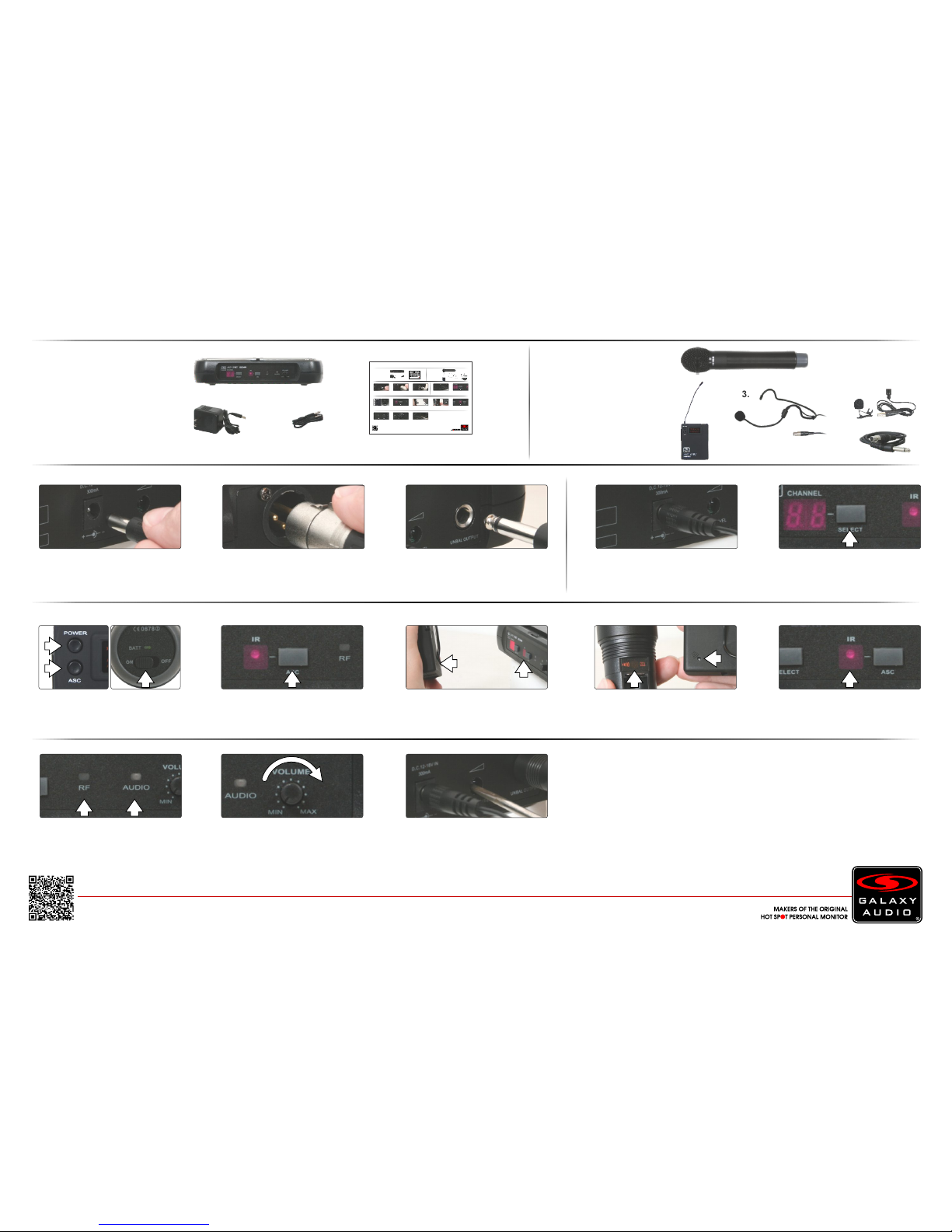
Included Components
1. ECM Receiver x1
3. Power Supply x1
4. Quick Start Guide x1
2. 1/4" Cable x1
1.
2 3 2
Setup
1
4.
2.
Insert the 5.5 mm plug into the DC
input jack, then plug the wall wart into a
120VAC outlet.
Press the “Select” button on the receiver
to choose a frequency number of 1-16.
Make sure the receiver is powered on.
(Powers on immediately when power
supply is plugged into the DC input jack)
1/4" Output: Connect 1 end of a shielded
1/4"M to 1/4"M cable to the receiver’s
1/4" output, then connect the other
end into your system input.
XLR Output: Connect a shielded
microphone cable to the receiver’s AF
XLRM output, then connect the other
end into your mixer input.
4.
3.
Operation
1
Optional Accessories
1. HH52 Handheld Mic
3. HS-U3BK Headset Mic
4. LV-U3BK Lav Mic
AS-GTR Guitar Cable5.
2. MBP52 Body Pack
1.
2.
For detailed instructions for finding the best frequencies, please consult the online manual.
3.
5.
When the transmitter is synced, the RF
presence indicator will illuminate. When
talking into the microphone the AF
presence indicator will illuminate.
6
4
Then press ASC on the receiver.
Use the level control to adjust the
volume. This will affect both the XLR
and 1/4" outputs.
7
Place the chosen transmitter with it’s IR
window facing the receiver IR window,
about 6" away.
5
5b
Receiver IR Window Location:
Center of the receiver face
3
To sync the handheld mic transmitter,
make sure to power on first. For the body
pack, power on and then press the ASC
button.
5a
Transmitter IR Window Locations:
Handheld IR is located inside the battery
compartment. Body Pack IR is located
on the backside bottom corner.
The Mute Level is factory set and
normally needs no adjustment. However,
you may turn clockwise if interference is
present.
8
GALAX Y AUDIO Quick Start Guide
ECM
Wireless Microphone System
Included Components
1. ECM Receiver x1
3. Power Supply x1
4. Quick Start Guide x1
2. 1/4" Cable x1
1.
2 3 2
Setup
1
4.
2.
Insert the 5.5 mm plug into the DC
input jack, then plug the wall wart into a
120VAC outlet.
Press the “Select” button on the receiver
to choose a frequency number of 1-16.
Make sure the receiver is powered on.
(Powers on immediately when power
supply is plugged into the DC input jack)
1/4" Output: Connect 1 end of a shielded
1/4"M to 1/4"M cable to the receiver’s
1/4" output, then connect the other
end into your system input.
XLR Output: Connect a shielded
microphone cable to the receiver’s AF
XLRM output, then connect the other
end into your mixer input.
4.
3.
Operation
1
Optional Accessories
1. HH52 Handheld Mic
3. HS-U3BK Headset Mic
4. LV-U3BK Lav Mic
AS-GTR Guitar Cable5.
2. MBP52 Body Pack
1.
2.
For detailed instructions for finding the best frequencies, please consult the online manual.
3.
5.
When the transmitter is synced, the RF
presence indicator will illuminate. When
talking into the microphone the AF
presence indicator will illuminate.
6
4
Then press ASC on the receiver.
Use the level control to adjust the
volume. This will affect both the XLR
and 1/4" outputs.
7
Place the chosen transmitter with it’s IR
window facing the receiver IR window,
about 6" away.
5
5b
Receiver IR Window Location:
Center of the receiver face
3
To sync the handheld mic transmitter,
make sure to power on first. For the body
pack, power on and then press the ASC
button.
5a
Transmitter IR Window Locations:
Handheld IR is located inside the battery
compartment. Body Pack IR is located
on the backside bottom corner.
The Mute Level is factory set and
normally needs no adjustment. However,
you may turn clockwise if interference is
present.
8
GALAXY AUDIO Quick Start Guide
ECM
Wireless Microphone System
Included Components
1. ECM Receiver x1
3. Power Supply x1
4. Quick Start Guide x1
2. 1/4" Cable x1
1.
2 3 2
Setup
1
4.
2.
Insert the 5.5 mm plug into the DC
input jack, then plug the wall wart into a
120VAC outlet.
Press the “Select” button on the receiver
to choose a frequency number of 1-16.
Make sure the receiver is powered on.
(Powers on immediately when power
supply is plugged into the DC input jack)
1/4" Output: Connect 1 end of a shielded
1/4"M to 1/4"M cable to the receiver’s
1/4" output, then connect the other
end into your system input.
XLR Output: Connect a shielded
microphone cable to the receiver’s AF
XLRM output, then connect the other
end into your mixer input.
4.
3.
Operation
1
Optional Accessories
1. HH52 Handheld Mic
3. HS-U3BK Headset Mic
4. LV-U3BK Lav Mic
AS-GTR Guitar Cable5.
2. MBP52 Body Pack
1.
2.
For detailed instructions for finding the best frequencies, please consult the online manual.
3.
5.
When the transmitter is synced, the RF
presence indicator will illuminate. When
talking into the microphone the AF
presence indicator will illuminate.
6
4
Then press ASC on the receiver.
Use the level control to adjust the
volume. This will affect both the XLR
and 1/4" outputs.
7
Place the chosen transmitter with it’s IR
window facing the receiver IR window,
about 6" away.
5
5b
Receiver IR Window Location:
Center of the receiver face
3
To sync the handheld mic transmitter,
make sure to power on first. For the body
pack, power on and then press the ASC
button.
5a
Transmitter IR Window Locations:
Handheld IR is located inside the battery
compartment. Body Pack IR is located
on the backside bottom corner.
Place the chosen transmitter with it’s IR
window facing the receiver IR window,
about 6" away.
5
The Mute Level is factory set and
normally needs no adjustment. However,
you may turn clockwise if interference is
present.
6
Page 2
3. Q. Which setting do I use on the body pack transmitter?
A. For a headset or lapel microphone use “MIC”, for a line level input use “0dB” and for a guitar use “-10dB”.
Specifications subject to change without notice.
V20170502
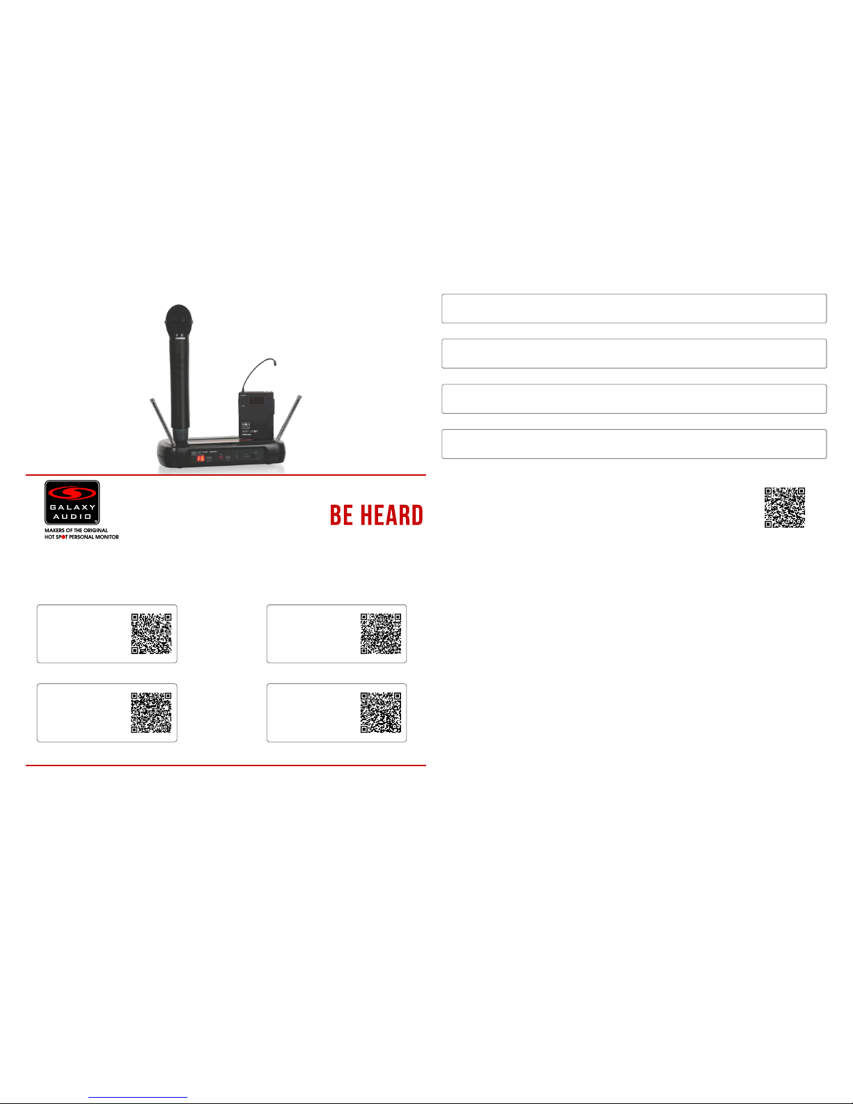
Other Helpful Sources
ECM
Manual
(PDF Download)
ECM
Product Page
ECM
Cutsheet
(PDF Download)
ECM
How To Video
Quick Start Guide
ECM
Wireless Microphone System
TM
FAQ
1. Q. I’m having problems finding the best frequency for me. Where do I go to find this information?
A. Please consult the online manual or visit: GalaxyAudio.com/support/schematics-and-frequency-charts
2. Q. With my transmitter off, the RF and AF lights are both on, and I get a lot of noise.
A. You are picking up outside interference and you need to change your frequency.
Printed in China
4. Q. How should I position the Antennas?
o
A. They should be at about 45 outward from a vertical position in each direction.
Wireless Tips
Maintain line of sight between the transmitter and receiver antennas.
Do not have walls, metal objects, large crowds, etc. blocking the line of sight between the transmitter and receiver.
Antennas on the stationary equipment should be kept several feet above the ground.
Antennas can be mounted on stands or walls using brackets such as the ANT-LB.
On body pack receivers/transmitters, avoid putting them in your pocket, and/or folding the antenna under the pack.
The antenna should hang freely and openly.
Keep the distance between transmitters and receivers as short as possible.
If distances above 20-30' are unavoidable, directional antennas such as the ANT-PDL can improve reception by
rejecting signals outside their pickup angle.
Find out what TV stations are broadcasting in your area and avoid the channels they are on.
This information is available from many sources on line, such as www.tvfool.com.
If your receiver is showing that it is receiving RF when your transmitter is turned off, you need to move to another
frequency.
If you are using several systems, you can contact service@galaxyaudio.com for assistance in
frequency coordination.
Make certain you are using fresh batteries, rechargeable batteries may be used, but they discharge at a much
faster rate than alkaline.
601 E. Pawnee Wichita, 67211 316. 263.2852 316.263.0642 www.galaxyaudio.comKS FAX
Distributed in Canada by Audio Distributors International (ADI) 1275 Newton, unit 6 Boucherville, QC J4B 5H2 Canada
450.449.8177 FAX 450.449.8180
The frequencies of the Galaxy UHF Wireless Systems are on frequencies that are used by Digital Television stations.
To be assured of the best performance, you should determine on what RF channels the DTV stations
in your area are broadcasting, then set your wireless systems on frequencies that are not being used.
For more information, please view the DTV Frequency Ranges & FCC Consumer Alert online at:
galaxyaudio.com/support/schematics-and-frequency-charts
 Loading...