

Page 1
MODULE INSTALLATION GUIDE
For
ANY SPOT TRAVELER AS-TV8
This guide provides installation instructions for the following Optional Function
Modules available for the Any Spot Traveler: AS-TVREC Wireless Mic/Audio Link
Receiver, AS-TVCD CD/MP3 Player, AS-TVTX Audio Link Transmitter, and ASTVEC Echo Module.
SAFETY NOTE: If you have any misgivings about your abilities to perform any of
these procedures, please allow Galaxy Audio or a qualified representative to do the work.
These procedures allow the user to install or remove any of these function modules
without disconnecting the internal batteries. However, please observe the following rules
when performing any operations listed in this guide:
1. Disconnect the AC power/charger cord from the Traveler and make sure the main
power switch and all module power switches are in the OFF position. This also
applies to any modules that you are preparing to install.
2. Remove any jewelry such as rings, bracelets, and wristwatches.
3. Once a panel or module is removed, do not probe inside the Traveler with any
metal object, such as a screwdriver. Even though the power switches are off, there
will still be voltage present at various places on the circuit boards, wires, and
connectors.
4. The plastic multi-pin connectors found on the wires are a locking type. Do not
pull on the wires to disconnect them. Rather, locate and disengage the release tabs
and pull gently on the plastic connector itself.
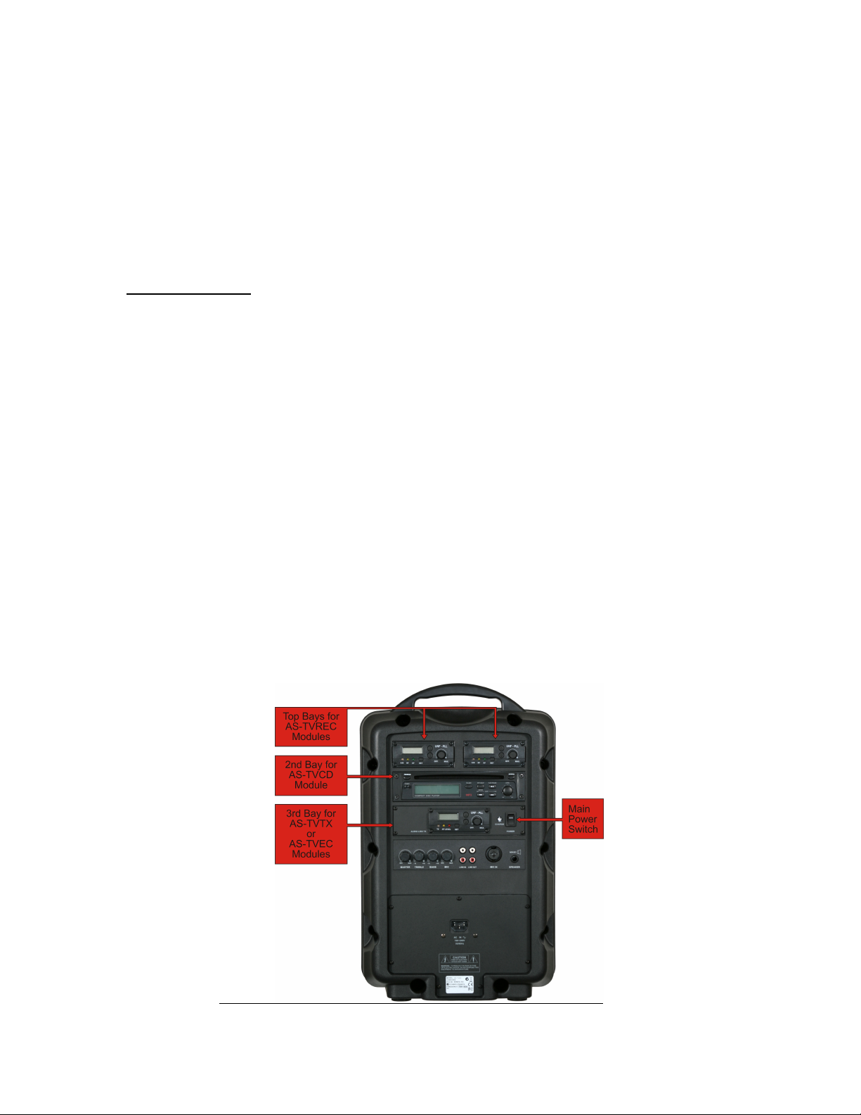
5. Each optional module must be installed only in the module bay designated for it.
Please see Photo 1, which shows locations where each module may be installed.
Photo 1.
Page 2
AS-TVREC Wireless Mic/Audio Link Receiver
1. This module is the easiest to install since there are no wires to connect (the
connector is a card type on the end of the module circuit board.) This module is to
be installed in only the top left or top right module bays (half width.) Two of
these modules may be installed into a single Traveler.
2. Using a 2mm Hex (Allen) wrench, remove the four screws securing the blank
panel of the module bay to be used. Remove the blank panel and set it aside.
3. Gently slide the AS-TVREC module into the bay (See Photo 2). The module
should slide in freely until about the last ¼” of the installation. At this point a
slight resistance will be encountered as you gently push on the module face to
engage the card’s connector. If you encounter any resistance before reaching this
point do not force it. Simply pull the module back out and start again.
4. Once the module is pushed in all the way, reinstall the four Hex head screws.
Photo 2.
AS-TVCD CD/MP3 Player
1. This module is to be installed only in the second bay down from the top.
2. Remove the four screws securing the blank panel using a Phillips head
screwdriver. Remove the panel and set it aside.
3. Looking inside the bay, locate the wire group and its 5-pin connector for the
TVCD module. This wire group will be found in the wiring harness to the right
side of the bay opening (See Photo 3). Gently pull the wires and connector out of
the bay opening as far as possible.
4. Verify that the wire colors are red, black, and a gray three-conductor cable. (If
there is an orange wire in this group, you have the wrong bundle.)
5. Plug the 5-pin wire connector into the connector in the rear of the TVCD module,
noting that there are alignment tabs that allow only one way of insertion (See
Photo 4). Make sure the plug is inserted all the way in until the tabs lock.
Page 3

6. Slide the TVCD module all the way into the bay, making sure no wires are
pinched in the process. Reinstall the four module mounting screws.
Photo 3. Photo 4.
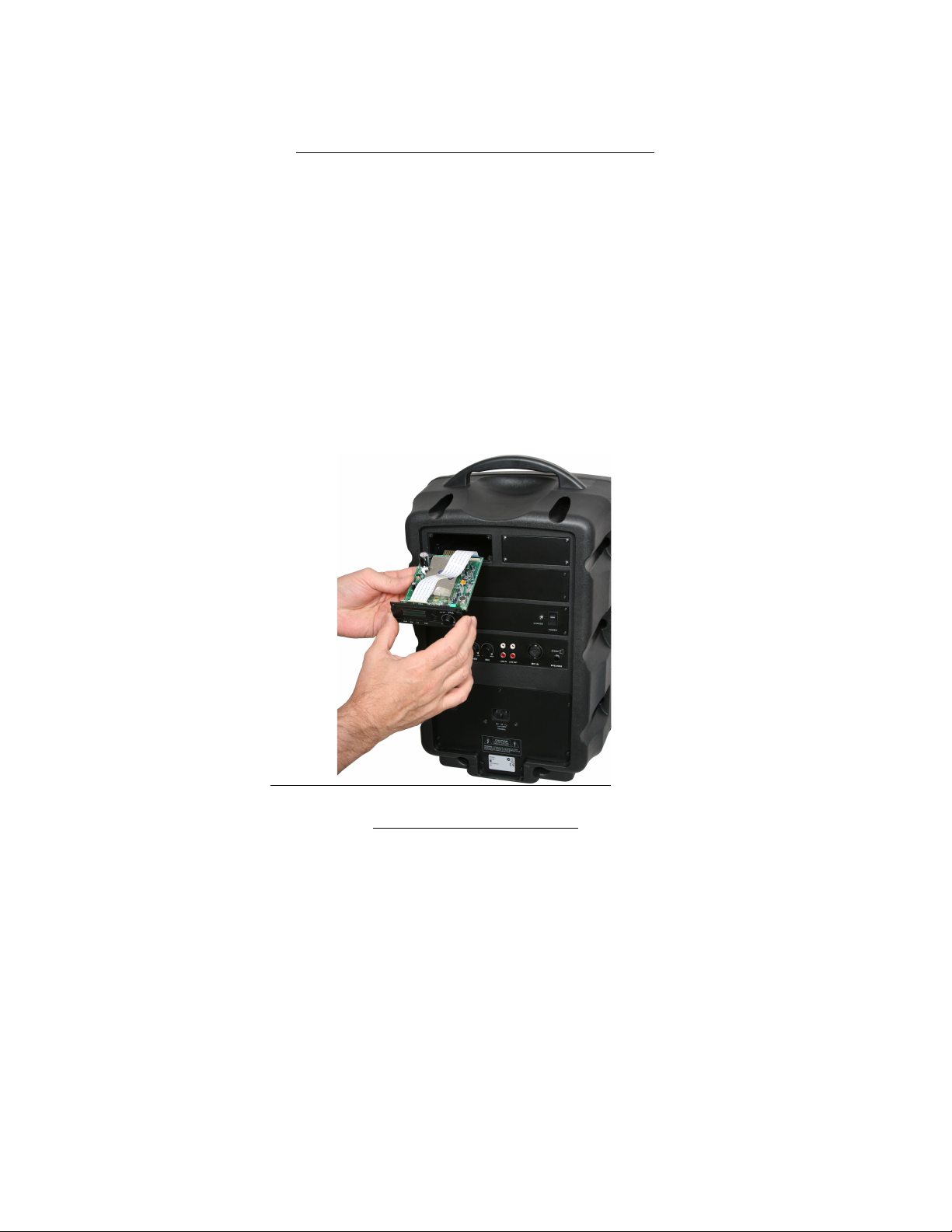
AS-TVTX Audio Link Transmitter and AS-TVEC Echo Module.
These two modules are to be installed only into the third bay down from the top. This
means that they cannot both be used simultaneously within the same Traveler. These
two module panels also contain the main Traveler power switch and charge LED.
This third bay down will always contain either one of these two modules or a panel
with only the main power switch and charge LED. Installation of these modules will
involve multi-pin connectors on the Traveler main circuit board. Photo 6 shows the
locations of these connectors on the main circuit board as seen through the third bay
opening.
Photo 6.
Page 4

AS-TVTX Audio Link Transmitter:
1. Remove the four panel mounting screws using a Phillips screwdriver. Remove the
existing panel from the bay opening as far as the attached wires will allow.
2. Look inside the bay opening and note the location of the 7-pin connector that
connects the wires from the main power switch to the main circuit board (See
Photo 5). Carefully remove this plug from the circuit board connector. Set aside
the removed panel.
3. Looking inside the bay opening, locate the 8-pin connector and wires emerging
from the left side of the main circuit board (See Photo 6). Leave the connector
attached at the circuit board but pull the free end of this wire group out of the bay
opening.
4. Plug this 8-pin wire connector into the connector at the rear of the TVTX module,
noting the alignment tabs. Make sure the plug is inserted all the way until the tabs
lock (See Photo 7).
5. Locate the wires and 7-pin connector coming from the main power switch on the
TVTX module. Plug this connector into the same 7-pin main circuit board
connector that was previously connected to the main power switch wires on the
removed panel (See Photo 6).
6. Looking inside the bay opening, locate the small switch on the top of the main
circuit board, near the rear edge (See Photo 6). Verify that this switch is in the
position labeled “Normal” (to the right.)
7. Locate the long black antenna wire that is attached to the TVTX module. Feed the
free end of this antenna wire into the bay opening and let it drop down over the
rear edge of the main circuit board (See Photo 8). Keep this antenna wire away
from the woofer cone area.
8. Carefully install the TVTX module panel into the bay opening, making sure not to
pinch any wires. Reinstall the four module panel mounting screws.
Photo 5.
Page 5

Photo 7.
Photo 8.
AS-TVEC Echo Module:
1. Remove the four panel mounting screws using a Phillips screwdriver. Remove the
existing panel from the bay opening as far as the attached wires will allow.
2. Look inside the bay opening and note the location of the 7-pin connector that
connects the wires from the main power switch to the main circuit board (See
Photo 5). Carefully remove this plug from the circuit board connector. Set aside
the disconnected panel.
3. Looking inside the bay opening, locate the 5-pin connector and wires emerging
from the left side of the main circuit board (See Photo 6). Leave the connector
attached at the circuit board but pull the free end of this wire group out of the bay
opening.
4. Plug this 5-pin connector into the connector located on the top of the TVEC
module circuit board (See Photo 9). Make sure the plug is installed all the way
until the tabs lock.
5. Locate the wires and 7-pin connector emerging from the main power switch on
the TVEC module. Plug this connector into the same 7-pin main circuit board
connector that was previously connected to the main power switch wires on the
removed panel (See Photo 6).
Page 6

6. Looking inside the bay opening, locate the small switch on the top of the main
circuit board, near the rear edge (See Photo 6). Verify that this switch is in the
position labeled “Effect” (to the left.)
7. Carefully install the TVEC module panel into the bay opening, making sure not to
pinch any wires. Reinstall the four module panel mounting screws.
Photo 9.
 Loading...