

Page 1
Page 2

Introduction.............................................................................................1
Before using theTV10, TV8 or TV5.........................................................2
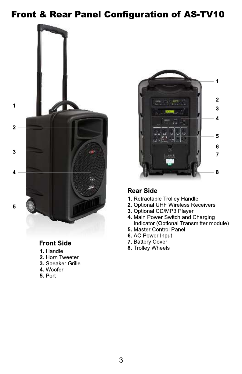
TV10 Front & Rear panel configuration..............................................3
TV10 Master Control Panel................................................................4
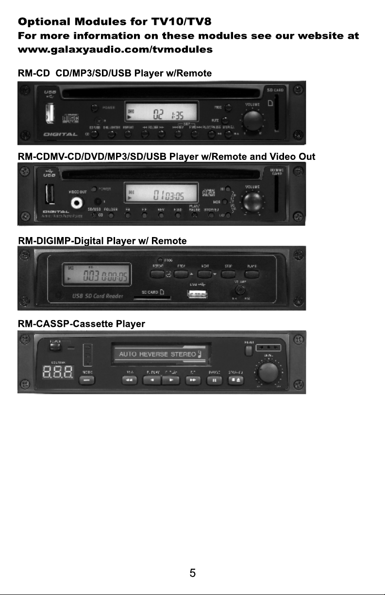
Optional Modules for TV10/TV8.........................................................5
Front Panel Configuration of AS-TV8 Series..........................................6
Rear Panel Configuration of AS-TV8 Series .........................................7
Description of Functions of AS-TV8 Series.......................................8-10
Operation of the AS-TV8.......................................................................11
Power Supply/Charger..........................................................................11
Power Switch........................................................................................11
Mixer.....................................................................................................11
In/Out Jacks..........................................................................................11
Speaker Out Jack.................................................................................11
Wireless Mic/Audio Link Receiver .......................................................12
Anti Shock CD/CMP Player..................................................................12
Digital Echo System..............................................................................13
Audio Link Transmitter..........................................................................13
Rear Panel of AS-TV5 Series………..........………………………..........13
Operation of TV5 and Optional Modules…………………………..........15
Optional Wireless Receivers...……………………………………...........15
Description of Functions for Handheld Microphone Front....................16
Description of Functions for Handheld Microphone Back.....................17
Operation of Handheld Microphone................................................18-20
Description of Functions for Body Pack Transmitter.............................21
Operation of Body Pack Transmitter................................................22-23
Maintenance.........................................................................................24
AS-TXRM Stationary Transmitter……………………………………. 25-26
Setup and Operation of TXRM…………………………………………...26
Specifications.................................................................................27-32
AS-TV10 Series...........................................................................27
AS-TV8 Series.....................................................................................28
AS-TV5 Series………………………………………………………..........29
Wireless Receiver Module (TV10, TV8, TV5)................…………..30-3 1
Digital Echo Module (TV8)...................................................................31
Audio Link Transmitter Module (TV8, TXRM)......................................31
Handheld Microphones...................................................................31-32
Body Pack Transmitter.........................................................................32
Page 3
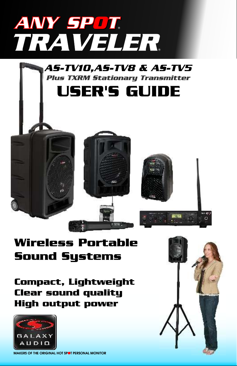
Thank you for purchasing the TV10/TV8/TV5 series wireless
portable sound systems. These units feature an “all in one” design
that allows them to be configured with a variety of different function
modules to suit your specific needs. With rich, full sound and plenty
of power, the TV10/TV8 series is ideally suited to cover large areas.
The TV5, with its compact size, is ideal for classrooms, conference
rooms, and guided tours. This manual covers the complete
functions and operations of the TV10/TV8, and TV5 including all
optional function modules. It also covers the TXRM Stationary
Transmitter, the TVHH/TVHHC Handheld Wireless Mics, and the
TVMBP Bodypack Transmitter. To use these systems to their fullest
potential please read this manual carefully.
Page 4

1. The TV10, TV8 and TV5 use a universal AC switching power supply/charger
that will operate on voltages of 100~240V,50/60Hz. The TV10, TV8 power
supplies are internal, while the TV5's is external. Verify that the voltage to
which you are connecting is in this range and then connect the AC power
cord from the Traveler to the wall outlet.
2. Charge the battery for at least 8 hours with the Power Switch OFF prior to
first time use to maintain the quality of the battery and provide maximum
operation time. When charging, the charging indicator lights RED. When
charging is almost complete, the indicator will flash alternately RED and
GREEN. After the battery is fully charged, the indicator will light GREEN.
After the initial charge the Traveler may be operated on either AC or Battery
power. When operating on AC power the Traveler will simultaneously
recharge its internal batteries.
3. These units have auto protection circuitry that will protect the battery from
being overcharged or overused. When running on battery power and the
power switch LED blinks RED, the battery power is down to 30%. When the
battery is nearly exhausted, the system will turn off automatically to protect
the battery.
Page 5
Page 6

a b c d e f
g
TREBLE control with center detent
a.
BASS control with center detent
b.
c. LINE IN volume control
d. AUX IN volume control
e. MIC2 volume control
f. MIC1 volume control
g. MASTER control for overall system volume
h. VOICE PRIORITY button to activate or end the microphone priority function
e.g. LED lights red meaning the voice priority function is active.
i. LINE-IN (RCA phone jack) to connect with external music sources including
CD/MP3/DVD/iPod players etc.
LINE OUT (RCA phone jack) to connect with external mixed-signal recorder or
active speaker system
j. AUX IN (3.5mm jack) to connect with external music sources including CD/MP3
DVD/iPod players etc.
AUX OUT (3.5mm jack) to connect with external mixed-signal recorder or active
speaker system
k. MIC IN 2 (6.3mm jack) microphone connector
l. MIC IN 1 (XLR / 6.3mm jack) combo microphone connector
h i j k l
Page 7
Page 8
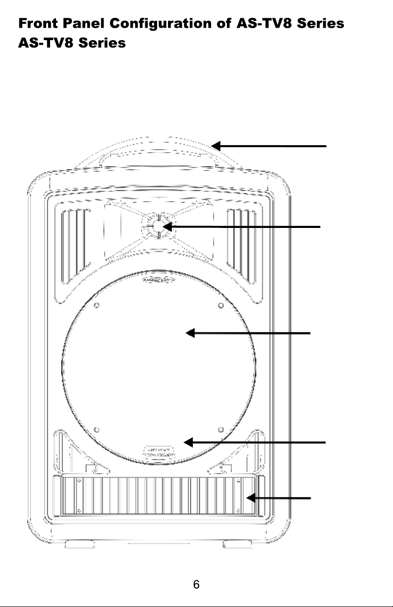
Handle
1" Horn
8" Woofer
Speaker
Grille
Heat Sink
Page 9
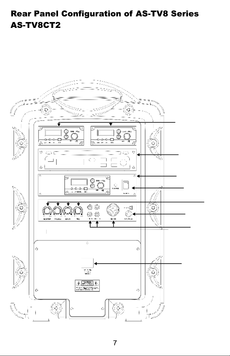
Receiver
Modules
CD/CMP Player
Audio Link
Transmitter
Power Switch
Mixer
Speaker Out
In/Out
Jacks
Power Supply/
Charging
Input
Page 10
Page 11
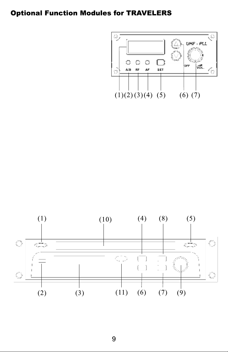
F. Wireless Microphone/Audio Link Receiver (AS-TVREC)
(for AS-TV5, TV8/TV10)
1. LCD display
2. A/B diversity indicator
3. RF indicator
4. AF level indicator
5. Channel Set
6. Channel selector
7. Power switch & mic. volume
G. Anti-Shock CD/CMP Player (RM-CD) (for TV8/TV10)
1. Program Playlist
2. Power switch
3. LCD display
4. Shuffle/Repeat
5. Stop/Eject
6. Search and play the previous track
7. Search and play the next track
8. Play/Pause
9. CD volume
10. CD slot
11. CMP Folder(Compressed Media Player)
Page 12

H1. Digital Echo System (AS-TVEC) (for AS-TV8)
1. Master echo volume control
2. Delay repeat control
3. Delay time control
4. Wired mic 1 volume control
5. Wired mic 2 volume control
6. Wired mic 1-1/4" input jack
7. Wired mic 2-1/4" input jack
H2. Audio Link Transmitter (AS-TVTX) (for AS-TV8/TV10)
1. LCD display
2. TX indicator
3. Low audio level indicator
4. High audio level indicator
5. Enter Setting
6. Channel selector
7. Power switch and volume control
Page 13

Operation of TV8 Portable Sound System
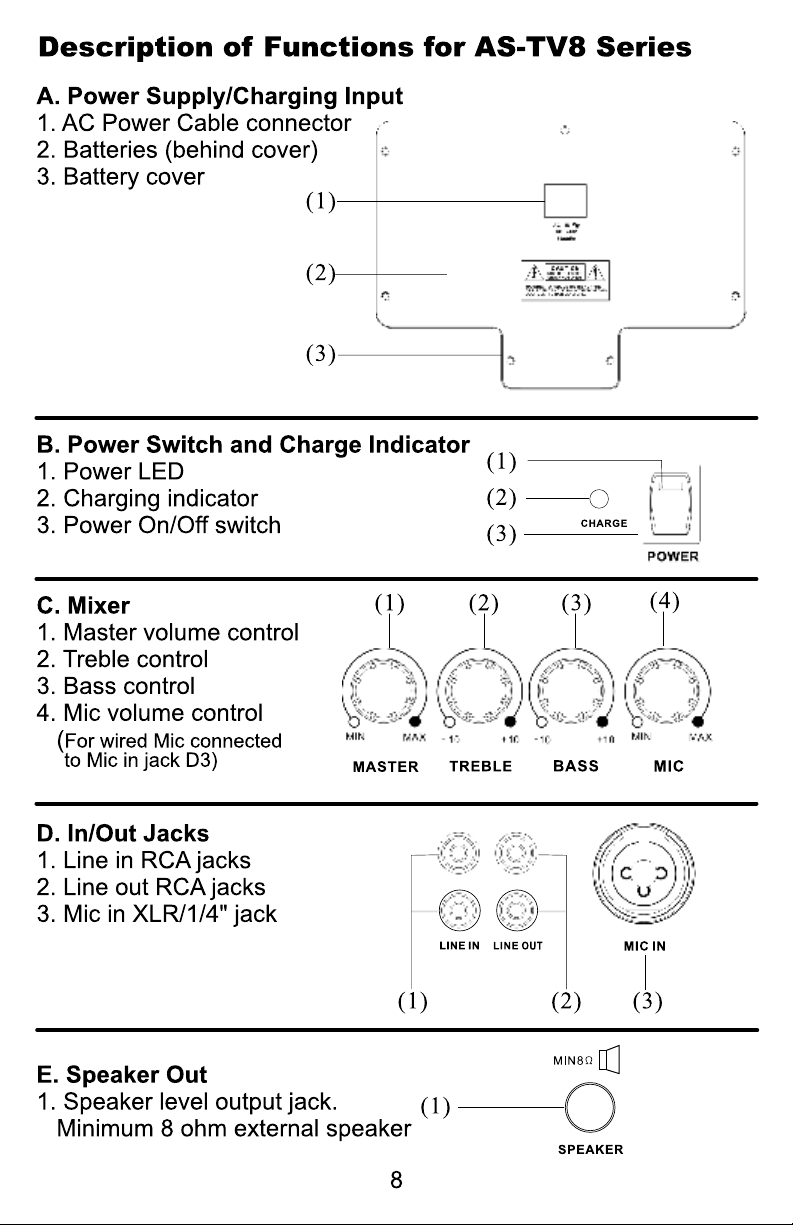
A. Power Supply/Charger (see page 8)
1. There is a universal AC switching power supply/charger built into the system
that will operate on voltages of 100~240V,50/60Hz. Verify that the voltage to
which you are connecting is in that range and then connect the AC power
cord from the AC IN (A1) to the wall outlet.
B. Power Switch and Charge Indicator (see page 8)
1. Power LED lights constant red under normal operation when power switch is
on. Blinking Power LED indicates 30% of battery power remaining.
2. When charging is almost complete, the indicator will flash RED and GREEN.
After the battery is fully charged, the indicator lights GREEN. The Universal
Power Supply/Battery Charger allows the Traveler to be used anywhere in
the world. The Traveler will operate for an unlimited time on AC power and
for about 6 hours on just battery power. A full recharge of the batteries takes
about 4 hours. The Traveler may be operated while recharging the batteries
without affecting the charge time. If a power failure occurs when operating
on AC, the Traveler will seamlessly switch over to battery power.
C. Mixer (see the page 8)
1. Master Volume Control.
2. Turn the Treble control (C2) counterclockwise to decrease the treble,
and turn clockwise to increase the treble. The center position (straight up)
produces a flat response.
3. Turn the Bass control (C3) counterclockwise to decrease the bass, and
turn clockwise to increase the bass. The center position (straight up) produces
a flat response.
4. Mic Volume for wired mic In jack (D3).
D. In/Out Jacks (see page 8)
1. The system contains Line In, Line Out, and Mic in jacks for connecting
external audio devices.
2. Line In (D1): RCA jacks to connect external audio sources, such as CD/
MP3 players or iPods. The volume of the Line In is controlled solely by the
Master (C1).
3. Line Out (D2): RCA jacks for sending the entire mix signal to other audio
devices, such as recorders, mixers, or power amps.
4. Mic In (D3): XLR or 1/4” (6.3mm) phone jack for wired microphones. Volume
of this input is controlled by Mic In (C4) and the Master (C1).
E. Speaker Out: (see page 8)
1. Used to connect to an external unpowered speaker (8Ω Min.)
Page 14

F. Wireless Mic/Audio link Receiver (AS-TVREC) (see page 9)
This system may include one or two receivers with selectable PLL 96 channel
operation. These modules receive signals from wireless Mics or from another
Traveler equiped with an Audio Link Transmitter.
1. Turn the power switch (F7) clockwise to turn on the receiver.
2. The LCD display (F1) will show “On” and the channel that was last in use
when the unit was turned off.
3. To select a different channel, press the set button (F5). The channel number
will flash in the in LCD display. Press the up or down button (F6) to select a
channel to use, and then press the set button. After a channel has been set,
press either the up or down button to display the frequency of the selected
channel.
4. Adjust the volume control to the desired level.
5. When receiving signal, the A/B diversity indicator (F2) will light RED or Green
to show the normal condition. The RF indicator (F3) will light to show RF
received and the AF indicator (F4) will show audio received.
G. Anti-Shock CD/CMP Player (RM-CD) (see page 9)
1. Push the power switch (G2) to turn on the player. Put a CD in the CD slot
(G10) or push the Stop/Eject button (G5) to take a CD out of the slot.
2. Press the Play/Pause button (G8) to start or pause CD/MP3 play .Turn the
volume control (G9) to adjust to the proper volume. Push the Stop/Eject button
to stop or change the CD or CMP (Compressed Media Player) disc.
3. Press the Forward (G7) or Reverse (G6) button to skip forward to the next rack
or reverse to the previous track. Holding down the Forward or Reverse button
will continuously forward or reverse the tracks.
4. Repeat/Shuffle (G4) has three modes:
1. Repeat one song
2. Repeat all songs
3. Shuffle for random play.
5. Create Program Playlist:
Step 1: Press Prog button (G1) to begin setting up the program playlist
Step 2: Select a song (see step 3 and 6)
Step 3: Press Repeat (G4) to enter the song. Repeat steps 2 and 3 to enter
additional songs.
Step 4: Press Play (G4) to play the programmed songs in memory
*Please note that the program will reset once the Program button is pressed
again.
6. To select a folder from an CMP, press Folder button (G11). Use Forward or
Reverse buttons to select a song.
Page 15

H1. Digital Echo System (AS-TVEC) (see page 10)
1. Turn the Echo Control (H1-1) clockwise to turn on the echo system. Then
use this control to adjust the level of echo in the mix. Echo will be applied to all
3 mic inputs.
2. Adjust the repeat button (H1-2) to select the number of repeats desired.
Adjust the delay button to select the delay time.
3. Mic input jacks (H1-6 and H1-7) are provided for connecting wired Mics. Mic
volume is controlled by H1-4 and H1-5 plus the Master (C-1, Pg.8).
H2. Audio Link Transmitter (AS-TVTX) (see page 10)
This module transmits the entire audio mix from one Traveler to another Traveler
equiped with a wireless Mic/Audio Link Receiver.
1. Turn the power switch (H2-7) clockwise to turn on the transmitter.
2. The LCD display (H2-1) will show “On” and the channel in use when the unit
was last turned off.
3. To select a different channel, press the set button (H2-5) and the channel will
flash in the LCD display. Press the up or down button (H2-6) to select the
transmit channel, and then press the set button again to enter the setting. The
LCD will then automatically display the selected channel. To display the
frequency of the selected channel press and hold either the up or down button.
4. Turn the volume control (H2-7) to adjust the audio transmit level. Use this
control in conjunction with the volume controls on the receiving Traveler.
5. When transmitting signal, the TX indicator (H2-2) will light Green to
show the transmitting condition. The AF Level indicator lights Yellow (H2-3) to
show a low audio level and lights Red (H2-4) to show high audio level.
6. Set up the receiving Traveler according to the procedure outlined in: F.
Wireless Mic/Audio Link Receiver on page 9. Select the same channel chosen
on the transmitting Traveler.
Page 16
Page 17

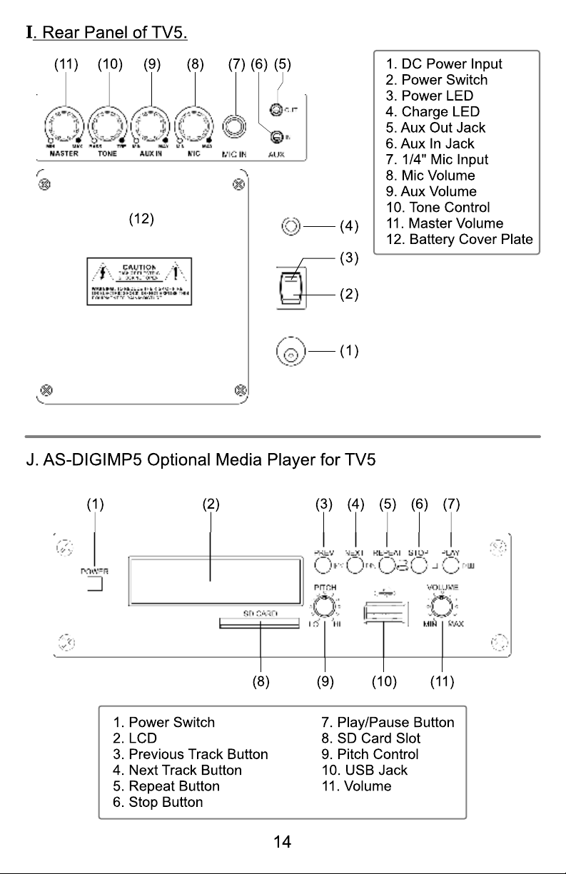
Operation of TV5 and Optional Modules (See Page 14)
1. For AC power operation or Charging: Connect the DC end of the
Power Supply/Charger cable to the DC In Jack (I1). Then connect the
other end (AC plug) to the AC wall outlet.
2. See page 2 for more information on Charging, Power Switch, and LED
Indicators.
3. The Aux Out Jack (I5) provides a Pre-Master, Pre-Tone line level
output of the entire mix.
4. The Aux In Jack (I6) is a line level input and is controlled by the Aux
Volume (I9).
5. The ¼" Mic Input (I7) will accept balanced or unbalanced, high or low
impedance mic signals, and is controlled by the Mic Volume (I8).
6. Turn the Tone control (I10) to the left for more bass and to the right for
more treble. This affects the entire mix of inputs, but not the Aux Out
signal.
7. The Master Volume (I11) controls the overall volume of the entire mix,
but has no effect on the Aux Out signal.
J. AS-DIGIMP5 Optional Media Player. (See page 14)
1. The AS-DIGIMP5 will play audio in the MP3 format from either SD
Cards or USB Devices. Press (J1) to switch on the power. The LCD
(J2) will display “C” when an SD card is inserted into the slot (J8), or
display the “USB symbol” when a USB device is plugged into the USB
Jack (J10). Track number, time counter, and play/pause status will also
be displayed. To switch from one format to the other, simply unplug
one media device and plug in the other.
2. Normal track play functions are controlled by buttons (J3) thru (J7).
The Repeat button (J5) offers three modes: Off, repeat track, and
repeat all tracks.
3. (J11) controls the volume. The Pitch (speed) of playback may be
altered up or down using (J9). For normal Pitch set the control to the
center detent.
For a Description and Operation of the Optional Wireless Microphone
Receiver (TVREC) (see pages 9 and 12).
Notice: Changes or modifications not expressly approved by the party responsible
for compliance could void the user's authority to operate the equipment.
IMPORTANT NOTE: To comply with the FCC RF exposure compliance
requirements, no change to the antenna or the device is permitted. Any change
to the antenna or the device could result in the device exceeding the RF
exposure requirements and void the user's authority to operate the device.
This device complies with Part 15 of the FCC Rules. Operation is subject to the
following two conditions: (1) this device may not cause harmful interference, and
(2) this device must accept any interference received, including interference that
may cause undesired operation.
Page 18

Wind Screen:
Pop Filter.
Main Body: Contains Wireless
Transmitter PCB.
SET button for channel settings
Protects cartridge with
LCD panel: Channel and frequency display.
UP and DOWN buttons: For Channel select and
Frequency display.
LED: Power status
Power Switch:
Charging Input: Remove lower housing to
access.
Page 19

Volume Control: Three level settings, including
mute, LOW and HI.
HI
LOW
HI
LOW
MUTE
Pushing point: Slide the battery cover down by
pressing here.
Battery Cover
Lower Housing: Remove to slide battery cover off or
to connect charger
Page 20

Operation of Handheld Microphone AS-TVHH/TVHHC
A. Battery Installation Steps:
1. Turn off the microphone before inserting batteries.
2. Press in the latch to release the lower housing and slide it off.
3. Press in the latch to release the battery cover and slide it down.
4. Insert 2 disposable batteries of 1.5V type or 2 rechargeable batteries of 1.2V
type.
5. Observe proper polarity while inserting batteries.
6. Slide the battery cover back to its original position.
7. Install the lower housing back to the lower part of the microphone.
B. Switch-On Steps:
1. Press the power switch and hold for about two seconds until the LED
turns to RED and "on" is displayed in the LCD.
2. The LCD will then automatically display the selected channel.
:Channel indicator.
:Press and hold the Up or Down button to display the
corresponding frequency.
C. Switch Off steps:
1. Press and hold power switch for about two seconds until the LCD displays
OFF.
D. Channel/Frequency Settings (with power on):
1. Press the SET button and hold for about 2 seconds.
2. The Channel number display will start flashing.
3. Press the Up button to display a higher numbered channel.
Page 21

4. Press the Down button to display a lower numbered channel.
5. Press the SET button to activate the selected channel.
E. LCD Indications:
1. :Three bars means batteries are fully charged.
2. :One bar indicates low batteries. Replace or recharge the
batteries.
3. :No bars showing indicates batteries are exhausted and after
flashing three times the power will automatically shut off.
F. Battery Charging Steps:
1. Rechargeable batteries need to be NiMH AA 1.2V with an amperage of
2100mAH or less as the charging function is limited to batteries of that
rating.
2.Recharging is best accomplished by using the AS-DCTVHH charger
3. Charging status:
a. Battery indicator flashing: Non-Rechargeable batteries installed or
no batteries installed. Check the batteries.
b. Battery indicator is flashing and LCD backlight is on: Failing,
corroded, or over-temperature batteries.
c. One or two bars showing: Batteries are charging successfully.
d. Three bars showing: Batteries have been fully charged.
* Please note the microphone will be turned off automatically while it is being
charged.
Page 22

G. Troubleshooting:
1. LED doesn't light when power switch is pressed to turn on mic.
a. Make sure that the batteries are not discharged.
b. Make sure that the batteries are installed correctly.
2. LCD shows when power switch is pressed to turn mic off.
Press the SET, UP and DOWN buttons at the same time in order to turn
a.
the microphone off automatically. The LCD display will flash about ten times
and then the microphone will turn off automatically. The microphone should
now turn on and off normally.
b. If the problem persists, call for service.
3. LCD panel shows unusual indications.
a. Remove the batteries from the microphone and re-install them.
4. No audio from microphone.
a. Check that the frequency of the transmitter is the same as that of the receiver.
b. Make sure that the Mic switch is not set to Mute.
c. Check if the distance between the transmitter and the receiver is too great.
d. Check if the transmitter or the receiver is too close to any large metal
objects.
5. Interference and signal Disturbance.
a. Make sure there are no other wireless systems operating on the same
frequency in the same area. This includes Microphones, televisions, radio
stations, etc. Try setting the transmitter and receiver to a new channel.
H. Q&A
1. Q: How long can the microphone be operated with fully charged batteries?
A: Re-chargeable batteries will last approximately8 to 10 hours. Disposable
batteries will last approximately 13 hours.
Q: How much time is required to recharge batteries from a fully exhausted
state.?
A: Approximately 4 to 5 hours.
Page 23

Description of Functions for Body Pack Transmitter
AS-TVMBP
1. Mini XLR Mic input jack (TA3M)
2. Power switch
3. Mute button
4. Antenna
5. Power light
6. Charging Jack
7. LCD light
8. Set button
9. Channel select button
10. Sensitivity control
11. 3.5mm aux input jack
12. Belt clip
13. Battery compartment
14. Battery cover
Page 24

Operation of Bodypack Transmitter
A. Battery Installation:
1. Switch the transmitter off before inserting batteries.
2. Slide the battery cover off.
3. Insert 2 disposable batteries (1.5V AA) or 2 rechargeable batteries (1.2V AA).
4. Observe correct polarity when inserting batteries.
5. Slide the battery cover back to its original position.
B. Turning unit on:
1. Switch the power to ON position
2. The RED LED will light and the LCD will display "On".
Battery status and channel will then appear.
If no other operation is performed, LCD light will go off automatically in 5
seconds.
C. Channel/Frequency Settings:
1. Press and hold the SET button for approximately 2 seconds until the channel
number flashes.
2. Release the SET button and the current channel will keep flashing
3. Press the UP or DOWN buttons to select a different channel.
4. When the desired channel is displayed press the SET button again. The
display will stop flashing and stay on the channel selected.
5. Press and hold the UP or DOWN buttons to display the frequency associated
with the channel number selected.
D. LCD Indications:
1. Batteries fully charged and channel 08 selected.
2. One bar displayed indicates low-battery. The batteries need to
be changed or rechargeable batteries need to be recharged.
3. No bars displayed indicates the batteries are exhausted and
after flashing three times, the power will automatically shut off.
Page 25

E. Battery Charging Steps:
1. Insure that the batteries are the rechargeable type.
2. Switch Power to OFF position.
3. Insert AS-TVMBP into its own intelligent charger stand (AS-DCTVMBP).
4. Batteries will recharge automatically.
5. For more details of charger stand please refer to AS- user guide.
DCTVMBP
F. Turning the unit OFF:
1. Slide the power switch to the OFF position.
2. LCD display will show “OFF”
If there is no further operation, the Power LED and LCD will switch off
automatically.
G. Troubleshooting
1. No LCD display when the unit is switched on.
a. Make sure the batteries are not discharged.
b. Make sure the batteries are installed correctly.
2.LCD shows Err when switched on.
a. Switch power OFF, repeat steps for turning unit on.
b. If the problem persists, call for service
3. No Audio from Transmitter.
a. Check that the Transmitter and Receiver are on the same channel.
b. Check if “MUTE” is activated.
c. Check if the volume control of the receiver is set to a proper position.
d. Check if the Transmitter and Receiver are within the operating distance
range.
4. Interference and signal disturbances.
a. When two Transmitters are being used, select different
frequencies. If voice disturbance still occurs try selecting another channel
until interference is gone.
b. Make sure there are no other wireless systems operating on the same
frequency in the area. This includes other wireless microphones,
television or radio stations, etc. Try setting the Transmitter and Receiver
to a new channel.
Page 26

Maintenance
Avoid Excessive Heat
Don't leave transmitter or receiver in hot sun, on a radiator, or near
other sources of high temperature.
Avoid Rough Handling
The transmitter and receiver may be damaged if dropped.
Storage
Before storage, fully charge the batteries in both transmitters and receivers. If
possible, recharge once a month during storage and again before first use.
Storage (Long term)
Remove the internal batteries when storing the units for a long period of time.
Replacing Batteries
Observe the correct polarity when installing batteries. Replace batteries
only with the same or equivalent type.
Battery Terminals
Keep the contacts clean and inspect them often to insure they are not corroded.
If they become corroded, polish them with a pencil eraser.
Page 27

AS-TXRM Stationary Transmitter
The AS-TXRM is a stand alone version of our AS-TVTX Audio Link
Transmitter module. The module is housed in a standard half-rack sized
enclosure, and includes a variety of inputs and outputs as well as mixing
controls. The TXRM is great for transmitting the entire mix from a mixing console
to one or more Traveler speakers equipped with wireless receivers.
Page 28

Setup and Operation of TXRM (See Page 24)
1. Starting with both the main power switch off (1) and the transmitter (8)
power switch off, plug the included power supply into the DC In jack
(18), and then plug the other end into an AC outlet. Connect the
supplied antenna to the Antenna Jack (11).
2. Set all volume controls (2), (5), & (9) to the minimum. Set the input TX
switches (3) and (6) to off, and then switch on the power (1).
3. Connect the desired source devices (such as a microphone or line
output of a mixer) to the appropriate TXRM inputs. The XLR input
(14) will accept balanced mic level signals. The ¼” input (16) will
accept unbalanced mic level signals, and provide 5v DC to condenser
mics when desired, by activating the switch (15). These two inputs
are controlled by the Mic Volume (2) and TX switch (3). The L/R Aux
Inputs will accept a stereo line level signal, and are controlled by the
Aux Volume (5) and TX switch (6). When the TX switches (3) and (6)
are engaged, the respective LEDs (4) and (7) will light, indicating that
the input signal is being sent to the Transmitter Module (8) and the
L/R Aux Output jacks.
4. Switch on the Transmitter Module (8) and set it according to the Audio
Link System instructions provided on page 13.
5. Set the receiver(s) according to the Wireless Mic Receiver
instructions provided on page 12.
6. Start sending a signal from the source device and set various volume
controls (in the signal chain from the source to the receiving device)
to the desired levels. It is important to set the gain structure properly
to achieve the best signal to noise ratio. Normally you will want to set
the output of the source as high as possible without causing distortion
to the input of the following device, and so on down the line.
7. Signals sent to the L/R Aux Input will appear at the Headphone Jack
(10) and be controlled by the Phone Volume (9). Note: Signals from
the Mic Inputs (14) and (16) do not appear at the Headphone Jack.
8. The DC Output Jack (17) supplies 12v DC for charging or powering
other devices. Make sure any device connected to this jack complies
with the voltage and current rating listed for this jack.
Page 29

CAUTION
Danger of explosion if the battery is incorrectly installed.
Replace only with the same or the equivalent type.
Sensitivity
Maximum SPL
Frequency response
Speakers
Receiver module (optional)
Antenna
Output power
Signal to noise ratio
CD/Media players (optional)
Audio link TX (optional)
Audio input
Audio output
Controls
Power requirement
92 dB, 1Watt @ 1 M
112 dB
20 Hz ~ 20 kHz (audio)
10" LF woofer, 1" HF tweeter
AS-TVREC x 2 @ diversity
Built-in antenna
100 Watt (RMS), 140W (MAX) @ 4 Ω
Up 70 dB
RM-CD/CDM/CDMV/DIGIMP/CASSP/CASS
(optional)
AS-TVTX transmitter (optional)
XLR - Mic in, 6.5 mm - Mic in, RCA - Line in,
3.5 mm - Aux in
RCA - Line out, 3.5mm - Aux out
Wireless, MIC, Bass, Treble, Master, AUX & LINE
100-240V AC 50/60Hz
Battery
Operating life
Charging time
Operating distance
Dimensions (D x W x H)
Weight
12V, 4.5Ah * 2 (Lead-Acid) rechargeable batteries
4 ~ 6 Hours (tested at 10+ hours)
5 Hours
164' - 197' (50 - 60 meters)
(D) 12.2" x (W) 14.17" x (H) 22.83"
(310mm x 360mm x 580 mm)
44 lbs (20 kg) (batteries included)
Page 30

CAUTION
Danger of explosion if the battery is incorrectly installed.
Replace only with the same or the equivalent type.
Sensitivity
Maximum SPL
Frequency response
Speakers
Receiver module (optional)
Output power
Signal to noise ratio
CD/Media player (optional)
Audio link TX (optional)
Audio input
Audio output
Controls
92 dB, 1Watt @ 1 M
112 dB
70 Hz ~ 20 kHz (audio)
8" LF woofer, 1" HF horn
AS-TVREC x 2 diversity (optional)
50 W RMS, 80 W MAX.
Up 70 dB
RM-CD/CDM/CDMV/DIGIMP/CASSP/CASS
(optional)
AS-TVTX transmitter (optional)
XLR-Mic. In, RCA-Line in
RCA-Line out, SPK Out (unswitched)
Mic., Line, Bass, Treble, Master
Power requirement
Battery
Operating life
Charging time
Dimensions (D x W x H)
Weight
100-240V AC 50/60Hz
12V, 2.9Ah * 2 (Lead-Acid) rechargeable batteries
4 ~ 6 Hours
4 ~ 6 Hours
12" x 9" x 18.5" (300 x 230 x 470 mm)
26.5lbs (12 kg)
Page 31

Sensitivity
92 dB, 1Watt @ 1 M
Maximum SPL
Frequency response
Speakers
Receiver module
Output power
Signal to noise ratio
Optional Media Player
Audio input
Audio output
Controls
Power requirement
Battery
100 dB
Hz ~ kHz (audio)70 16
5" Full Range
AS-TVREC x 2 diversity (optional)
30 W RMS, 50 W MAX.
Up dB70
AS- (optional) DIGIMP5
¼"-Mic. In, 1/8"-Aux In
1/8"-Aux Out,
Master, Tone, Aux In, Mic
100-240V AC 50/60Hz Power Supply/Charger
12V, 2.9Ah (Lead-Acid) rechargeable battery
Operating life
Charging time
Dimensions (D x W x H)
Weight
4 ~ 6 Hours
4 ~ 6 Hours
10.25" x 8.25" x 11.5" (260 x 210 x 292 mm)
9lbs (4.1 kg)
Page 32

Oscillation type
PLL synthesized control OSC
Adjustable frequency
Switching bandwidth
Ambient temperature
Maximum deviation
Dynamic range
T. H. D.
Pre/De- emphasis
Squelch
Frequency response
Operating range
Antenna mode
Sensitivity
Pre-programmed max. 96 switchable channels
Max. 12 MHz
-10 ºC ~ 50 ºC
50 kHz, with level limiting
110 dB
Less than 0.5%
50 sµ
Tone key and noise lock dual-squelch
70 Hz ~ 16 kHz (wireless)
160 - 230 feet (50 ~ 70 M) (open field)
with built-in antenna
Diversity
4 V @ 30 dB SINADµ
Double intermediate
Display status
Channel select
RF spurious rejection
Adjacent channel performance
IMD rejection
Carrier frequency range
110.6 Mhz / 10.7 MHz
LCD indicator displays channel or frequency
SET, UP, DOWN keys
70 dB
68 dB @ 250kHz
58 dB
640 ~ 664 MHz
Page 33

Antenna
Built-in or external
Dimensions ( L x W x H )
Weight
RF output
Spurious emission
Display status
Channel select
Antenna
Dimensions ( L x W x H )
Weight
Input sensitivity
5.25" x 3.46" x 1.45" (133 x 88 x 37 mm)
3.88 oz. (110 g)
10mW
Less than 250 nW
LCD indicator displays channel or frequency
SET, UP, DOWN keys
Built-in or external
4.25" x 7.5" x 1.75" (108 x 190 x 44 mm)
5.99 oz. (170 g)
10 mV
Delay time
Audio input
Controls
Microphone type
RF output
Spurious emission
Display status
110 ms ~ 340 ms
6.3 -Mic in * 2 TRS, Low 2
Echo, Repeat, Delay, MIC1, MIC2
Cardioid dynamic capsule
10mW
Less than 250 nW
LCD indicator displays channel or frequency,
battery condition
Page 34

Channel select
SET, UP, DOWN keys
AF controls
Battery
Battery life Ni-MH rechargeable
Battery life Alkaline disposable
Antenna
Dimensions ( Dia x L )
Weight with battery
Microphone Type
RF output
Spurious emission
Display status
Hi/Low/Mute switch
1.2 V (Ni-MH 1300 mAh) * 2 AA type rechargeable battery
1.5V * 2 AA Alkaline disposable
11 hours typical
14 hours typical
Built-in
1.8" x 10.4" (46 x 264 mm)
9.87 oz. (280 g)
Condenser mic.
10mW
Less than 250 nW
LCD indicator displays channel or frequency,
battery life
Channel select
AF controls
Audio input
Battery
Battery life Ni-MH rechargeable
Battery life Alkaline disposable
Housing
Dimensions ( D x W x H )
Weight with battery
SET, UP, DOWN keys
Mute switch, Hi/Mid/Low switch
Mic in, Aux in
1.2 V (Ni-MH 1300 mAh) * 2 AA type rechargeable battery
1.5V * 2 AA Alkaline disposable
11 hours typical
14 hours typical
Aluminium
1.04" x 2.52" x 3.48" (27 x 64 x 88 mm)
4.48 oz. (127 g)
Page 35

A RETURN AUTHORIZATION (RA) NUMBER MUST BE OBTAINED from Galaxy Audio prior
to any items being returned to Galaxy Audio for return or repair.
Galaxy Audio warrants the materials and workmanship of its products as follows:
A limited THREE YEAR Warranty applies to the following products:
1. HOT SPOTS-including HSRG, HSVC, PA6S, & PA6SR
2. MICRO SPOTS-including MSVC, MSPM, MSPA(DC)
3. CRICKET Polarity Test Set
4. JACKS IN THE BOX – including the MULTI MIXER
5. Hot Spot Accessories
6. The TRAVELER SERIES is supported with a 3 year warranty on speaker components and
casing, 1 year warranty on wireless and CD/MP3 player components.
A limited ONE YEAR Warranty applies to the following products:
1. CHECKMATE Series-including CM130, CM140, CM150, CM160, CM-C200 and accessories
2. ANY SPOT Series-including AS-1000(R)(T), AS-900, 1100, 1500 SERIES, DHT, TRC, PSE,
TOUR GUIDE/TRANSLATOR SYSTEMS & WIRELESS CAMERA KITS
3. ANY SPOT Accessories & Components
4. Any units containing a battery will have a 90 day warranty on the battery.
The following are not covered by the warranty:
1. Damage to or deterioration of the exterior of the item which occurs after delivery
2. Damage after initial delivery resulting from accident, misuse or neglect
3. Damage resulting from failure to follow instructions contained in the owner's manual
4. Damage resulting from the performance of repairs by someone other than the Galaxy Audio
repair department
5. Damage occurring during the shipment or delivery of any Galaxy Audio product to Galaxy
Audio after initial delivery of the product to you.
6. Damage to any Galaxy Audio product which has been altered or on which the serial number
has been effaced or removed.
7. Damage to or deterioration of the exterior of the item which occurs after delivery
Galaxy Audio does not authorize any third party including any dealer or Service Center to
assume any liability on behalf of Galaxy Audio or to make any warranty for Galaxy Audio
DEFECTIVE MERCHANDISE POLICY-WARRANTY
A RETURN AUTHORIZATION (RA) NUMBER MUST BE OBTAINED from Galaxy Audio prior
to any items being returned to Galaxy Audio for return or repair. Contact customer service @
(800)369-7768.
The Galaxy Audio warranty policy is to repair and return defective merchandise. Items
under warranty may be replaced at no charge if deemed un-repairable by the Galaxy Audio
technician. Proof of purchase may be required to verify warranty status. Customer will be
responsible for shipping charges to repair facility, repaired product will be returned shipping
prepaid by Galaxy Audio. Freight charges will not be reimbursed. Credit for defective warranty
merchandise must have authorization from the Galaxy Audio main office before credit will be
issued and will be subject to applicable restock and replacement charges. A twenty (20%)
restock fee will apply to warranty items returned for credit. The cost of replacement parts to
bring the item back to “like new” condition will also be deducted from credit for warranty items
DEFECTIVE MERCHANDISE POLICY-NON WARRANTY
A RETURN AUTHORIZATION (RA) NUMBER MUST BE OBTAINED from Galaxy Audio prior
to any items being returned to Galaxy Audio for return or repair. Repair charges are $30.00 per
hour (no minimum) plus parts. Customer will be responsible for all shipping charges.
Prepayment is expected if customer is not set up with open account terms in advance.
Discounts are not applicable on repairs. Open account terms for repairs will be Net Thirty (30)
days. Some items past the warranty time period may qualify for a standard replacement cost.
Please contact Galaxy Audio for more information.
Page 36

 Loading...