

Page 1
Page 2

Page 3

Contents
Introduction .......................................................................................... 1
Front Panel/Mic Receiver Module..........................................................2
Rear Panel ............................................................................................2
Operation................................................................................................3
Power Supply and Main Power Switch...................................................3
Output Jacks.......................................................................................... 3
Wireless Mic Receiver Module............................................................3-4
Description of Functions for Handheld Microphone Front......................6
Description of Functions for Handheld Microphone Rear.......................7
Operation of Handheld Microphone...................................................8-10
Description of Functions for Body Pack Transmitter..............................11
Operation of Body Pack Transmitter................................................12-13
Maintenance.........................................................................................14
Specifications..................................................................................15-17
Wireless Mic Receiver Module...............................................................15
Handheld Microphone..........................................................................16
Bodypack Transmitter...........................................................................17
Page 4

Operating Manual for AS-QUAD Series
**Please visit for the latest updates**www.galaxyaudio.com
Introduction
Thank you for purchasing the Galaxy Audio AS-QUAD
System. This manual covers the complete functions and
operation of the QUAD as well as the optional transmitters.
Please read this manual carefully to use the Quad to its
fullest potential. The Quad is a single space rack mount
receiver chassis, which may be loaded with up to 4 UHF
diversity wireless mic receivers. Each of the receivers
features an LCD display, 96 selectable channels, RF/AF
indicators, and volume control. The chassis has an
individual balanced XLR output for each receiver, and a
mix output (balanced XLR and unbalanced ¼” jacks) with a
Hi/Low level switch. The mix output provides a mixed
signal from all of the receivers, based on the individual
volume control settings. This mix output is very useful
when main mixer input channels are in short supply. The
internal antenna distribution system allows the 2
detachable antennas to serve all of the receivers. In
addition, the Quad chassis provides power to all 4
receivers while occupying only 1 AC outlet.
There are multiple transmitter options for the Quad
receivers. Choose between Dynamic or Condenser
Handheld Microphones or a Body Pack transmitter (with
multiple Headset & Lav options). Each transmitter features
an LCD display showing channel number, frequency, and
battery level. All transmitters feature a mute switch and run
off of 2AA batteries (can be rechargeable).
1
Page 5
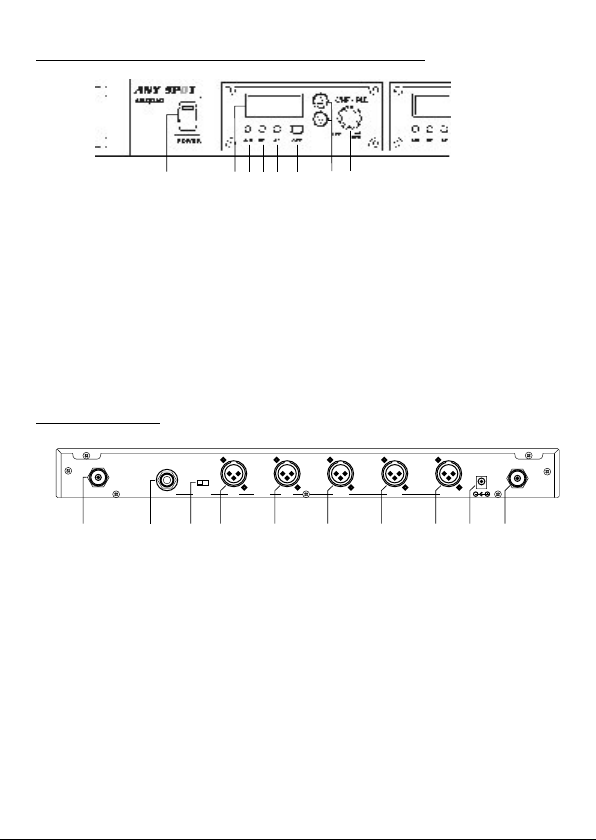
Front Panel / Mic Receiver Module
(8)
(2)(1) (3)(4) (5) (6) (7)
1. LCD Display
2. A/B Diversity Indicator
3. RF Indicator
4. AF Level Indicator
5. Channel Set
6. Channel Selector
7. Module Power Switch & Mic Volume
8. Main QUAD Power Switch
Rear Panel
ANT.B
9. Antenna B Connector
10. Unbalanced ¼” Mix Output
11. Mix Output Level Switch
12. Balanced XLR Mix Output
13. Module Ch. D Output
14. Module Ch. C Output
15. Module Ch. B Output
16. Module Ch. A Output
17. 12v DC Power Input
18. Antenna A Connector
LOW/HI
UN-BAL
MIXER
BAL.
AF OUT
CH.D CH.C CH.B CH.A
(10)(9) (11) (12) (13) (14) (15) (16) (17) (18)
DC INPUT
12~15V/2A
ANT.A
2
Page 6

Operation
A. Power Supply and Main Power Switch
1. Starting with all power switches off, plug the included
DC Power Supply into the DC Input Jack (17) on the rear
panel. Plug the other end into an AC wall outlet. Switch on
the Main Power (8).
B. Output Jacks
The QUAD offers two different methods of connecting the
Mic Receiver Outputs to the Inputs of devices such as
mixers, amplifiers, or recording gear.
1. You may connect each Receiver Module Output (A
through D, 13-16) to separate input channels on a
mixer. This method is useful when independent signal
processing or routing of the Mic Receivers is required.
Note: The Module Ch. A Output jack (16) corresponds
to the module closest to the Main Power Switch (8) on
the front panel, and so on down the line.
2. Or, you may simply use one (or both) of the Mix
Outputs (10 or 12), which will supply a mix of all the
Receiver Modules based on the Volume settings of
each Module (7). Use the Hi / Lo Switch (11) to
choose the overall Output Level (Mic or Line Level).
This method is useful to conserve mixer input
channels, or when a simple setup is desired that does
not require independent signal processing or routing
of the Mic Receivers.
C. Wireless Mic Receiver Modules
This system may be configured with up to four wireless mic
receiver modules with selectable PLL 96 channel
operation.
3
Page 7

1. Turn the power switch (7) clockwise to turn on the
receiver.
2. The LCD display (1) will show “On” and the channel that
was last in use when the unit was turned off.
3. To select a different channel, press the set button (5).
The channel number will flash in the in LCD display. Press
the up or down button (6) to select a channel to use, and
then press the set button. After a channel has been set,
press either the up or down button to display the frequency
of the selected channel.
4. Adjust the volume controls to the desired level. It is
important to set the gain structure properly to ensure the
best signal to noise ratio. Typically, you will want to set the
Output Volume controls of the Mic Receiver Modules as
high as possible without causing distortion to the Input of
the next device, and so on down the line.
5. When receiving signal, the A/B diversity indicator (2) will
light RED or Green to show the normal condition. The RF
indicator (3) will light to show RF received and the AF
indicator (4) will show audio received.
6. When multiple Transmitters (Mics) are used, each must
be set to a different channel to avoid interference. Set the
Mic Receiver to the same channel number that is set on
the Transmitter that you wish to receive.
Notice: Changes or modifications not expressly approved
by the party responsible for compliance could void the
user's authority to operate the equipment.
4
Page 8

IMPORTANT NOTE:
To comply with the FCC RF exposure compliance
requirements, no changes to the antenna or the device are
permitted. Any change to the antenna or the device could
result in the device exceeding the RF exposure
requirements and void the user's authority to operate the
device. This device complies with Part 15 of the FCC
Rules. Operation is subject to the following two conditions:
(1) this device may not cause harmful interference, and
(2) this device must accept any interference received,
including interference that may cause undesired operation.
5
Page 9
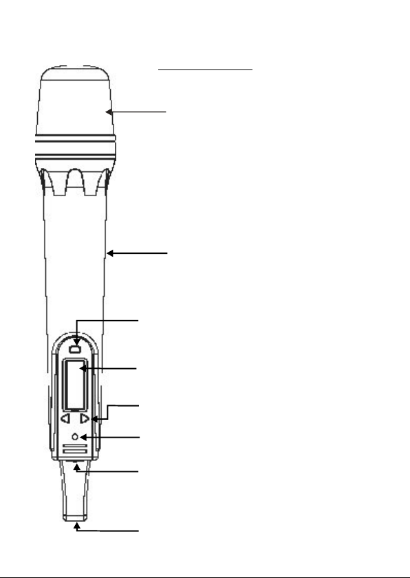
Description of Functions for Handheld Microphone
AS-TVHH/TVHHC
Front Panel
Wind Screen:
with Pop Filter.
Protects cartridge
Main Body: Contains Wireless
Transmitter PCB.
SET button for channel settings
LCD panel: Channel and frequency display.
UP and DOWN buttons: For Channel select
and Frequency display.
LED: Power status
Power Switch:
Charging Input: Remove lower housing to
access.
6
Page 10

Description of Functions for Handheld Microphone
AS-TVHH/TVHHC
Rear Panel
Volume Control: Three level settings,
including mute, LOW and HI.
HI
LOW
MUTEHI
LOW
Pushing point: Slide the battery cover down
by pressing here.
Battery Cover
Lower Housing: Remove to slide battery cover
off or to connect charger
7
Page 11

Operation of Handheld Microphone
A. Battery Installation Steps:
1. Turn off the microphone before inserting batteries.
2. Press in the latch to release the lower housing and slide it off.
3. Press in the latch to release the battery cover and slide it down.
4. Insert 2 disposable batteries of 1.5V type or 2 rechargeable batteries of 1.2V
type.
5. Observe proper polarity while inserting batteries.
6. Slide the battery cover back to its original position.
7. Install the lower housing back to the lower part of the microphone.
B. Switch-On Steps:
1. Press the power switch and hold for about two seconds until the LED
turns to RED and “on” is displayed in the LCD.
2. The LCD will then automatically display the selected channel.
: Channel indicator.
: Press and hold the Up or Down button to display the
corresponding frequency
C. Switch Off steps:
1. Press and hold power switch for three seconds until the LCD displays OFF.
D. Channel/Frequency Settings (with power on):
1. Press the SET button and hold for about 2 seconds.
2. The Channel number display will start flashing.
3. Press the Up button to display a higher numbered channel.
8
Page 12

4. Press the Down button to display a lower numbered channel.
5. Press the SET button to activate the selected channel.
E. Battery Indications:
1. :Three bars means batteries are fully charged.
2. :One bar indicates low batteries. Replace or recharge the
batteries.
3. :No bars showing indicates batteries are exhausted and after
flashing three times the power will automatically shut off.
F. Battery Charging Steps:
1. Rechargeable batteries need to be NiMH AA 1.2V with an amperage of
2100mAH or less as the charging function is limited to batteries of that
rating.
2. Recharging is best accomplished by using the AS-TV8DCC charger
3. Charging status:
a. Battery indicator flashing: Non-Rechargeable batteries installed or
no batteries installed. Check the batteries.
b. Battery indicator is flashing and LCD backlight is on: Failing,
corroded, or over-temperature batteries.
c. One or two bars showing: Batteries are charging successfully.
d. Three bars showing: Batteries have been fully charged.
* Please note the microphone will be turned off automatically while it is being
charged.
9
Page 13

G. Trouble Shooting:
1. LED doesn't light when power switch is pressed to turn on mic.
a. Make sure that the batteries are not discharged.
b. Make sure that the batteries are installed correctly.
2. LCD shows when power switch is pressed to turn mic off.
Press the SET, UP and DOWN buttons at the same time in order to turn
a.
the microphone off automatically. The LCD display will flash about ten times
and then the microphone will turn off automatically. The microphone should
now turn on and off normally.
b. If the problem persists, call for service.
3. LCD panel shows unusual indications.
a. Remove the batteries from the microphone and re-install them.
4. No audio from microphone.
a. Check that the frequency of the transmitter is the same as that of the receiver.
.
b Make sure that the Mic switch is not set to Mute.
.
c Check if the distance between the transmitter and the receiver is too great.
.
d Check if the transmitter or the receiver is too close to any large metal objects.
5. Interference and signal Disturbance.
a. Make sure there are no other wireless systems operating on the same
frequency in the same area. This includes Microphones, televisions, radio
stations, etc. Try setting the transmitter and receiver to a new channel.
H. Q&A
1. Q: How long can the microphone be operated with fully charged batteries?
A: Re-chargeable batteries will last approximately 8 to 10 hours. Disposable
batteries will last approximately 13 hours.
Q: How much time is required to recharge batteries from a fully exhausted
state?
A: Approximately 4 to 5 hours.
10
Page 14

Description of Functions for Body Pack Transmitter
AS-TVMBP
1. Mini XLR Mic input jack (TA3M)
2. Power switch
3. Mute button
4. Antenna
5. Power light
6. Charging Jack
7. LCD light
8. Set button
9. Channel select button
10. Sensitivity control
11. 3.5mm aux input jack
12. Belt clip
13. Battery compartment
14. Battery cover
11 12
Page 15

Operation of Bodypack Transmitter AS-TVMBP
A. Battery Installation:
1. Switch the transmitter off before inserting batteries.
2. Slide the battery cover off.
3. Insert 2 disposable batteries (1.5V AA) or 2 rechargeable batteries (1.2V AA).
4. Observe correct polarity when inserting batteries.
5. Slide the battery cover back to its original position.
B. Turning unit on:
1. Switch the power to ON position
2. The RED LED will light and the LCD will display "On".
Battery status and channel will then appear.
If no other operation is performed, LCD light will go off automatically in 5
seconds.
C. Channel/Frequency Settings:
1. Press and hold the SET button for approximately 2 seconds until the channel
number flashes.
2. Release the SET button and the current channel will keep flashing
3. Press the UP or DOWN buttons to select a different channel.
4. When the desired channel is displayed press the SET button again. The
display will stop flashing and stay on the channel selected.
5. Press and hold the UP or DOWN buttons to display the frequency associated
with the channel number selected.
D. Battery Indications:
1. Batteries fully charged and channel 08 selected.
2. One bar displayed indicates low-battery. The batteries need to
be changed or rechargeable batteries need to be recharged.
3. No bars displayed indicates the batteries are exhausted and
after flashing three times, the power will automatically shut off.
Page 16

E. Battery Charging Steps:
1. Insure that the batteries are the rechargeable type.
2. Switch Power to OFF position.
3. Insert AS-TVMBP into its own intelligent charger stand (AS-DCTVMBP).
4. Batteries will recharge automatically.
5. For more details of charger stand please refer to AS-DCTVMBP user guide.
F. Turning the unit OFF:
1. Slide the power switch to the OFF position.
2. LCD display will show "OFF"
If there is no further operation, the Power LED and LCD will switch off
automatically.
G. Troubleshooting
1. No LCD display when the unit is switched on.
a. Make sure the batteries are not discharged.
b. Make sure the batteries are installed correctly.
2.LCD shows Err when switched on.
a. Switch power OFF, repeat steps for turning unit on.
b. If the problem persists, call for service
3. No Audio from Transmitter.
a. Check that the Transmitter and Receiver are on the same channel.
b. Check if "MUTE" is activated.
c. Check if the volume control of the receiver is set to a proper position.
d. Check if the Transmitter and Receiver are within the operating distance
range.
4. Interference and signal disturbances.
a. When two Transmitters are being used, select different
frequencies. If voice disturbance still occurs try selecting another channel
until interference is gone.
b. Make sure there are no other wireless systems operating on the same
frequency in the area. This includes other wireless microphones,
television or radio stations, etc. Try setting the Transmitter and Receiver
to a new channel.
13
Page 17
Maintenance
Avoid Excessive Heat
Don't leave the transmitter or receiver in the hot sun, on a radiator, or near
other sources of high temperature.
Avoid Rough Handling
The transmitter and receiver may be damaged if dropped.
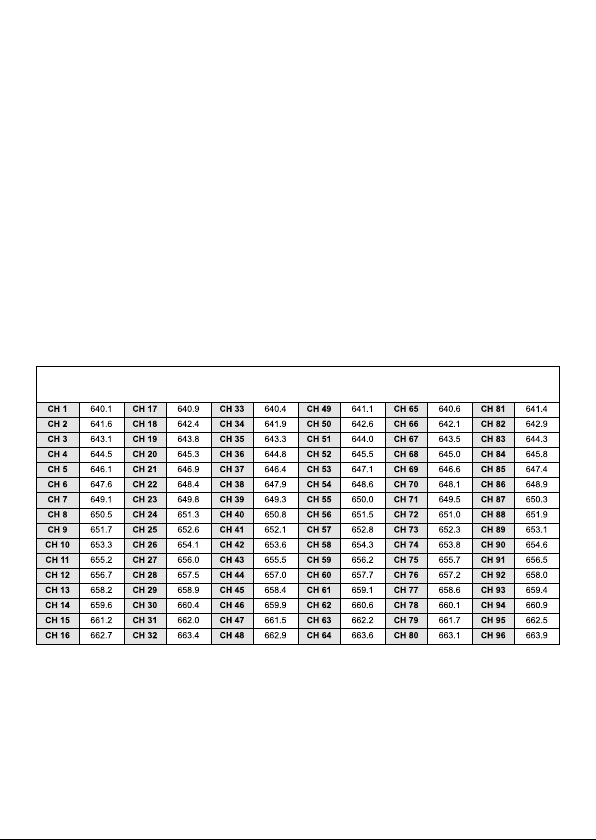
640MHz Frequency Chart
14
Page 18
Specifications
Wireless Mic Receiver Module AS-TVREC
Oscilla tio n type
Carrie r fre quency range
Adjusta ble fre quency
Switching bandwidth
Ambie nt temperature
Maxim um devia tio n
Dynamic range
T. H. D.
Pre /D e- emphasis
Squelch
Frequency response
Opera tin g range
Antenna mode
Sensitivity
Double in termediate
Display status
Channel select
RF spurio us reje ctio n
Adjacent channel performance
IMD rejectio n
PLL syn thesized control OSC
640 ~ 664 MHz (96 ch.) (See chart pg.14)
Pre-programmed max. 96 switch able channels
Max. 12 MHz
-10 ºC ~ 50 ºC
50 kHz, with level limiting
110 dB
Less tha n 0.5%
50 sµ
Tone key and noise lock dual- squelch
70 Hz ~ 16 kHz (wirel ess)
160 - 23 0 feet (50 ~ 70 M) (ope n field)
with built-in antenna
Dive rsi ty
4 V @ 30 dB SINADµ
110.6 Mhz / 10.7 MHz
LCD indica tor displ ays ch annel or frequ ency
SET, UP, DOWN keys
70 dB
68 dB @ 25 0k Hz
58 dB
15
Page 19
Wireless Mic Receiver Module AS-TVREC (continued)
Antenna
Dimensions ( L x W x H )
Weight
Buil t-in or ex terna l
5.25 " x 3.46 " x 1.45 " (133 x 88 x 37 mm)
3.88 oz. (110 g)
Handheld Microphone AS-TVHH/TVHHC
Micro phone ty pe
RF outp ut
Spurio us emis sion
Display status
Channel select
AF contro ls
Battery
Battery life Ni-M H recharg eable
Battery life Alkalin e disposable
Antenna
Cardioid (TVHH), or Condenser
(TVHHC) dynamic capsule
10mW
Less than 250 nW
LCD indi cator displ ays channe l or freque ncy,
battery condi tion
SET, UP, DOWN keys
Hi/Low /Mute switch
1.2 V (Ni -MH 1300 mAh) * 2 AA type rechargeabl e batt ery
1.5V * 2 AA Alkaline disposab le
11 hours typi cal
14 hours typical
Built-in
Dimensio ns ( Dia x L )
Weight with battery
1.8" x 10. 4" (46 x 264 mm)
9.87 oz. (280 g)
16
Page 20
Bodypack Transmitter AS-TVMBP
Mic Type
RF output
Condenser mic (Multiple options of Headset and
Lav Mics available).
10mW
Spurious emis sion
Display status
Channel select
AF controls
Audio input
Battery
Battery lif e Ni-M H re charg eable
Battery lif e Alkalin e disposable
Housing
Dimensio ns ( D x W x H )
Weight with battery
Less than 250 nW
LCD indicator displ ays channel or frequ ency,
battery life
SET, UP, DOWN keys
Mute switch, Hi/Mid/Lo w switch
Mic in, Aux in
1.2 V (N i-MH 1300 mAh) * 2 AA type rech arge able battery
1.5V * 2 AA Alkaline dispo sable
11 hours typical
14 hours typical
Aluminium
1.04" x 2.52" x 3.48" (27 x 64 x 88 mm)
4.48 oz. (127 g)
17
Page 21

REGISTRATION CARD
Registration information is used ONLY by GALAXY AUDIO and will be
kept strictly confidential. You can also register online at
www.galaxyaudio.com/Registration.jsp
What magazines do you read?_________
_________________________________
_________________________________
__________________________________
_________________________________
How can Galaxy Audio better serve you?
_________________________________
_________________________________
_________________________________
_________________________________
__________________________________
Name________________________Phone_____________
Registration
Address________________________________________
City, State, Zip____________________________________
email_______________________
Serial number Model
This Galaxy Audio product will be used for:
Live Sound o
Church o
Recording
Home/Project Studio o
Commercial Studio o
Dealer_______________________PurchaseDate________
Post-Production/Mastering o
Broadcast
On-Air o
Production o
Page 22

WICHITA, KS 67216-0285
P.O. BOX 16285
GALAXY AUDIO
STAMP
PLACE
HERE
Page 23

LIMITED WARRANTY
This warranty gives you specific legal rights, and you may also have other rights which may
vary from state to state. This warranty is extended to the purchaser and to any purchaser
from him for value.
GALAXY AUDIO warrants the materials and workmanship of its products from the date of the
original purchase.
1. Hot Spot Series, Micro Spot Series, Audio Solutions (including Cricket, Jacks In the Box,
& Check Mate) are products covered by 3 year warranty.
2. Any Spot Wireless, including Wireless Personal Monitor (WPM), Assistive Listening
System, 500 Series Wireless Microphone, 700 Series Wireless Microphone, Lightweight
Headset Microphones, Tour Guide/Translator System, Wireless Camera Kit are covered
by a 1 year warranty.
3. The Traveler is supported with a 3 year warranty on speaker components and casing, and
a 1 year warranty on wireless and CD/MP3 player components.
4. Any units containing a battery will have a 90 day warranty on the battery.
The following are not covered by the warranty:
1. Damage to or deterioration of the exterior cabinet which occurs after delivery.
2. Damage after initial delivery resulting from accident, misuse or neglect.
3. Damage resulting from failure to follow instructions contained in the owner's manual.
4. Damage resulting from the performance of repairs by someone other than GALAXY
AUDIO or an authorized GALAXY AUDIO service center.
5. Damage occurring during the shipment or delivery of any GALAXY AUDIO product to
GALAXY AUDIO or an authorized service center after initial delivery of the product to you.
6. Damage to any GALAXY AUDIO product which has been altered, or on which the serial
number has been effaced or removed.
If your unit requires service, it must be returned, shipping charges prepaid to GALAXY AUDIO
in the United States. (This warranty is not enforceable outside the U.S.) Please call or write
GALAXY AUDIO, 601 E. Pawnee, Wichita, Kansas 67211, (316) 263-2852. We will then issue
you to an RMA# (Return Merchandise Authorization) which will need to be applied to the
returned item. Under no circumstances should you return your unit to the factory without
receiving an RMA or written instruction to do so. If service is required, you must present the
original or a copy of the bill of sale as a proof of date of purchase of your unit. Upon receipt of
your unit for service, GALAXY AUDIO will repair or replace your unit as soon as possible, but
in no event later than 30 days after the receipt of the unit. We will return the unit to you,
shipping charges prepaid, provided the necessary repairs are covered by this warranty.
IMPLIED WARRANTIES OF MERCHANT ABILITY AND FITNESS FOR PARTICULAR
PURPOSE ARE LIMITED IN DURATION TO THE LENGTH OF THIS WARRANTY, UNLESS
OTHERWISE PROVIDED FOR BY STATE LAW. GALAXY AUDIO'S LIABILITY IS LIMITED
TO THE REPAIR OR REPLACEMENT, AT OUR OPTION, OF ANY DEFECTIVE PRODUCT,
AND SHALL IN NO EVENT INCLUDE INCIDENTAL OR CONSEQUENTIAL DAMAGES OF
ANY KIND. SOME STATES DO NOT ALLOW LIMITATIONS ON HOW LONG AN IMPLIED
WARRANTY LASTS AND/OR DO NOT ALLOW THE EXCLUSION OR LIMITATION OF
INCIDENTAL OR CONSEQUENTIAL DAMAGES, SO THE ABOVE LIMITATIONS AND
EXCLUSIONS MAY NOT APPLY TO YOU.
GALAXY AUDIO does not authorize any third party, including any dealer or Authorized
Service Center, to assume any liability on behalf of GALAXY AUDIO or to make any warranty
for GALAXY AUDIO.
Page 24

V09222008
 Loading...