

Page 1
USER'S MANUAL
www.galaxyaudio.com/AS1100.php
Page 2
USING THIS SYSTEM AT EXCESSIVE VOLUMES CAN CAUSE PERMANENT HEARING DAMAGE.
USE AS LOW A VOLUME AS POSSIBLE.
W
ARNING!
In order to use this system safely, avoid prolonged listening at excessive sound pressure levels. Please use the following guidelines established by
the Occupational Safety Health Administration (OSHA) on maximum time exposure to sound pressure levels before hearing damage occurs.
90 dB SPL at 8 hours
95 dB SPL at 4 hours
100 dB SPL at 2 hours
105 dB SPL at 1 hour
It is difficult to measure the exact Sound Pressure Levels (SPL) present at the eardrum in live applications. In addition to the volume setting on the
Personal Monitors, the SPL in the ear is affected by ambient sound from floor wedges or other devices. The isolation provided by the fit of quality
earpieces is also an important factor in determining the SPL.
Here are some general tips to follow in the use of this product to protect your ears from damage.
• Turn up the volume control only far enough to hear properly.
• Ringing in the ears may indicate that the gain levels are too high. Try lowering the gain levels.
• Have your ears checked by an audiologist on a regular basis. If you experience wax buildup in your ears, stop using the system until an
audiologist has examined your ears.
• Wipe the ear molds with an antiseptic before and after use to avoid infections. Stop using the earphones if they are causing great discomfort
or infection.
110 dB SPL at ½ hour
115 dB SPL at 15 minutes
120 dB SPL — avoid or damage may occur
READ these instructions.
KEEP these instructions.
2.
HEED all warnings.
3.
FOLLOW all instructions.
4.
DO NOT use this apparatus near water.
5.
CLEAN ONLY with dry cloth.
6.
DO NOT block any ventilation openings. Install in accordance with the manu-
7.
facturer's instructions.
DO NOT install near any heat sources such as radiators, heat registers, stoves,
8.
or other apparatus (including amplifiers) that produce heat.
DO NOT defeat the safety purpose of the polarized or grounding-type plug. A
9.
polarized plug has two blades with one wider than the other. A grounding type
plug has two blades and a third grounding prong. The wider blade or the third
prong are provided for your safety. If the provided plug does not fit into your
outlet, consult an electrician for replacement of the obsolete outlet.
PROTECT the power cord from being walked on or pinched, particularly at plugs,
10.
convenience receptacles, and the point where they exit from the apparatus.
ONLY USE attachments/accessories specified by the manufacturer.1.
11.
UNPLUG this apparatus during lightning storms or when unused for long periods of
12.
time.
REFER all servicing to qualified service personnel. Servicing is required when the
13.
apparatus has been damaged in any way, such as power-supply cord or plug is damaged, liquid has been spilled or objects have fallen into the apparatus, the apparatus
has been exposed to rain or moisture, does not operate normally, or has been
dropped.
DO NOT expose the apparatus to dripping and splashing. DO NOT put objects filled
14.
with liquids, such as vases, on the apparatus.
15.
Remove the batteries from the receiver if the system will not be used for a long
period of time. This will avoid any damage resulting from a defective, leaking
battery.
16.
DO NOT throw used batteries into a fire. Be sure to dispose of or recycle used
batteries in accordance with local waste disposal laws.
LICENSING INFORMATION
THIS RADIO EQUIPMENT IS INTENDED FOR USE IN PROFESSIONAL ENTERTAINMENT
AND SIMILAR APPLICATIONS.
Changes or modifications not expressly approved by Galaxy Audio Incorporated could void your
authority to operate the equipment. Licensing of Galaxy Audio wireless microphone equipment is
the user's responsibility, and licensability depends on the user's classification and application, and
on the selected frequency. Galaxy Audio strongly urges the user to contact the appropriate
telecommunications authority concerning proper licensing, and before choosing and ordering
frequencies.
NOTE: THIS EQUIPMENT MAY BE CAPABLE OF OPERATING ON SOME FREQUENCIES NOT
AUTHORIZED IN YOUR REGION. PLEASE CONTACT YOUR NATIONAL AUTHORITY TO
OBTAIN INFORMATION ON AUTHORIZED FREQUENCIES FOR WIRELESS MICROPHONE
PRODUCTS IN YOUR REGION
Licensing: Note that a ministerial license to operate this equipment may be required in certain
areas. Consult your national authority for possible requirements.
FCC Con su mer Aler t fo r Wirel es s Micro ph ones (U .S .)
Most us er s do not ne ed a l icens e to o perat e th is wire le ss micr ophone sy stem. Nev erthe le ss,
opera ti ng this m ic ropho ne s ystem w it hout a li ce nse is su bject to ce rtain res trict io ns: the s ys tem may
not cau se h armfu l in terfe re nce; it m us t opera te a t a low pow er level (n ot in exces s of 50 mil li watts );
and it ha s no p rotec ti on from i nt erfer en ce rece iv ed from a ny other de vice. Pur chase rs s hould a ls o be
aware t ha t the FCC i s cu rrent ly e valua ti ng use of w ir eless m icropho ne system s, and th es e rules a re
subje ct t o chang e.
For mor e in forma ti on, cal l th e FCC at 1- 88 8-CAL L- FCC (TT Y: 1-888-T ELL-F CC ) or visi t th e FCC's
wirel es s micro ph one web si te at www. fc c.gov /c gb/wi re lessm icropho nes
Page 3
Introduction
Introduction
Thank you for choosing a Galaxy Audio Wireless Personal Monitor system. You have joined
thousands of other satisfied customers. Our years of professional experience in design and
manufacturing ensure our products' quality, performance and reliability.
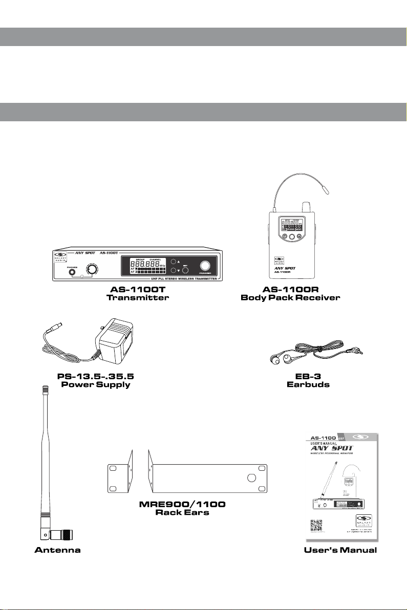
System Components
System Components
All AS-1100 systems include the following components:
AS-1100T Transmitter
AS-1100R Receiver
Power Supply
One Pair EB-3 Earbuds
One Antenna
Rack Ears
User Manual
SET
2
Page 4

AS-1100T Transmitter Features:
AS-1100T Transmitter Features:
Front Panel:
1
1
Headphone Jack.
2
3
Transmitter Menu Down Button.
Please See (system setup) on page 4 .
2
Headphone Output Level Contro l.
Turn left to decrease the level,
turn right to increase the level.
3
LCD screen.
Please See (System Setup) on pa ge 4 .
6
Transmitter Set Button.
Please See (System Setup) on page 4 .
On/Off Swit ch .
7
Press and hold two seconds to turn On ,
press and hold to turn Off.
4
Transmitter Menu Up Button.
Please See (System Setup) on pa ge 4 .
Back Panel:
1 2 3 4 5 6 7
1
DC Power Input Jack.
4
Right Channel XLR/1/4" Combo
Input Jack.
2
Stereo/Mono Switch.
Stereo position preserves Lef t/ Ri gh t
5
Left Channel Input Level Contro l.
signals throughout system. Mo no
position mixes Left/Right sig na ls t og et he r.
6
Right Channel Input Level Contr ol .
3
Left Channel XLR/1/4" Combo Inp ut J ac k.
7
Antenna Jack. 50 ohms.
4
556
7
3
Page 5

System Setup
System Setup
GRO UP CHA NNEL
L
A F
R
A F
1
GRO UP CHA NNEL
L
A F
R
A F
2
GRO UP CHA NNEL
L
A F
R
A F
3
GRO UP CHA NNEL
L
A F
R
A F
4
Receiver screen
GROU P C HANNE L
R
F
A F
STE REO MO NO
GROU P C HANNE L
R
F
A F
STE REO MO NO
GROU P C HANNE L
R
F
A F
STE REO MO NO
MH z
5
MH z
6
MH z
7
MH z
MH z
MH z
MH z
Transmitter Programming:
Selec t a Gr oup and /o r Chann el :
Press S ET butt on . While G ro up numb er i s flash in g, pres s or
butto n to s elect a g ro up as sho wn i n . The n pr ess SET b utton
1
again . Wh ile Cha nn el numb er i s flash in g, pres s or butt on to
selec t a Ch annel , as s hown in .
2
Note: W he n using m ul tiple s ys tems, f or o ptimu m re sults s et all
of the sy st ems to th e sa me grou p nu mber an d se lect a di ffere nt
chann el n umber f or e ach sys te m in that g ro up.
Audio I np ut Leve l Di splay :
Displ ay s left an d ri ght cha nn el audi o in put lev el , as show n in .
3
Full Di sp lay:
Displ ay s left an d ri ght cha nn el audi o in put lev el s and sel ected
frequ en cy, as s ho wn in .
4
Note: Ad ju st au di o input l evels t o pe ak on o nl y the lou dest si gn als .
Body Pack Receiver Programming
Selec t a Gr oup and /o r Chann el :
Press a nd h old SET b utton . Wh ile GRO UP numb er i s flash in g, pres s
or butto n to s elect a G ro up as sho wn i n . The n pr ess SET
again . Wh ile CHA NN EL is f lashi ng , press or b ut ton to
selec t a ch annel , as s hown in .
6
Batte ry S tatus :
Five le ve l Batte ry S tatus I nd icato r, as s hown in . R eplace ba tteri es
when in di cator s ta rts bli nk ing.
Stere o/ Mono Mo de D ispla y:
The STE RE O or MONO i nd icato r wi ll auto ma tical ly light to
8
displ ay t he type o f si gnal be in g recei ve d, as sel ec ted on th e
Tra nsmit te r.
Full Di sp lay:
Displ ay s Batte ry S tatus , RF /Audi o Le vel, St ereo/Mo no
Mode an d Se lecte d Fr equen cy, as sho wn i n .
GROU P C HANNE L
2
R F
A F
STE REO MO NO
MH z
8
GROU P C HANNE L
R F
A F
STE REO MO NO
5
7
9
MH z
9
4
Page 6

Body Pack Receiver
Body Pack Receiver
4321
L
E
N
N
CHA
P
ROU
G
z
H
M
F
5
5
6
R
F
A
O
N
O
M
EO
R
E
T
S
15
SET
87
Features:
1
Antenna.
2
RF Signal LED.
Lights when RF Signal is received .
3
Earphone Jack.
4
Output Level Control and On/Off S witch.
5
LCD Screen.
Please See (System Setup) on page 4 .
6
Receiver Menu Down Button.
Please See (System Setup) on page 4 .
7
Receiver programming SET Bu tt on.
Please See (System Setup) on page 4 .
8
Receiver Menu Up Button.
Please See (System Setup) on page 4 .
Wearing the Body Pac k Receiver
Clip the receiver to a belt. For best r es ul ts , sl id e th e receiver
until the belt is pressed against t he b as e of t he c li p.
-
+
+
-
SET
5
Changing Batte ries
Expected life for two Alkaline bat te ri es i s ap pr ox imately 6 hours.
When the LCD Battery Indicator is f la sh in g (s ee b el ow), the
batteries should be changed imm ed ia te ly, as shown on the left.
GROU P C HANNE L
R F
A F
STE REO MO NO
MH z
Page 7

Specifications
Specifications
System
Band: UHF
Frequency Range: CODE D 584~607 MHz
CODE L 655~679 MHz
Transmitter Output Level: 10dBm
Operating Range Under Typical Conditions
300' (92m)
Note: Actual range depends on RF signal
absorption, reflection, and interference.
Audio Frequency Response: +/-3dB 60Hz~16KHz
Total Harmonic Distortion: +/-30KHz deviation
1KHz tone <1%
Dynamic Range: >90dB A-weighted
Operating Temperature Range:
14ºF to 122ºF (-10º C to +50º C)
Note: battery characteristics may limit this range
Accessories and Replacement Parts
Accessories and Replacement Parts
Many of these parts and accessories may be found and purchased from the Galaxy Audio website in either the
Galaxy Store (www.galaxyaudio.com/store.php) or in the accessories tab of each products web page.
AS-EXTBNC - BNC Connector and Cable for front mounting the antennas on the DHTQUAD.
Transmitter
Max Audio input level: +6dBV
Gain Adjustment Range: 40dB
Input Impedance: 100KΩ
Dimensions: 1.5" x 8.3" x 3.78"
(38 x 212 x 96mm) (HWD)
Weight: 21oz. (605g)
Power Requirements: 12-18 VDC at
300 mA (supplied by external power supply)
XLR input:
Impedance balanced
Pin1 Ground (cable shield)
Pin2 Audio
Pin3 No Audio
Body Pack Receiver
Audio Output Level: 100mW
Sensitivity: -94dBm for 30dB
Image Rejection: >55dB
Dimensions: 3.74" x 2.6" x 1"
(95 x 65 x 25mm) (HWD)
Weight: 3.5oz. (100g) without batteries
Power Requirements: 2 (AA) size
alkaline or rechargeable batteries
Battery Life: About 5 hours
AS-ANTBNC - Replacement BNC Antenna for use with Galaxy Audio Wireless Personal
Monitors. (Part number will vary based on the Frequency Code of specific unit)
AS-CLIP911R - Replacement Belt Clip for AS-900, AS-1100, MBP52, & MBP64
PS-13.5-.35.5 - 600mA Replacement Power Supply for AS-900, AS-1100, AS-1800, VES,
VSC, ECD, ECM, PSE, & DHT.
AS-UA12-14.5 - 1000mA Universal Power Supply for Replacement Power Supply for AS-900,
AS-1100, AS-`1800, VES, VSC, ECD, ECM, PSE, DHT, DHTRQUAD, & CTS. Includes
adapters for most other countries.
ANT-PDL - Directional antenna used to decrease interference to other equipment. Frequency
range 500-900MHz The UHF wide-band (500-900 MHz) directional LPDA (log periodic dipole
array) antenna reduces outside interference while providing increased send/receive signal
range. Each antenna paddle is matched to 50 ohms impedance with a low-loss BNC
connector; 7dBi gain. For permanent or temporary installation; mounts to 5/8"-27 threads.
EB3 - Ear buds which come standard with our Wireless Personal Monitor Systems with 1/8" -
3.5mm Jack.
EB3S - Replacement Sleeves for EB-3 Ear Buds. 5 pair in each pack. Available in Small,
Medium, or Large.
MRE900/1100 - Replacement Single Rack Kit for AS-900 & AS-1100: 2 pieces with screws.
BATTCVR11005264 - Replacement Battery Cover for AS-1100 Body Pack.
6
Page 8

THRE E Y EAR LIMIT ED W ARRANTY
WARRANTY Information can be viewed online at
http://www.galaxyaudio.com/warranty.php
USER'S MANUAL
Specifications in this manual are subject to change without notice.
For the most up to date manual and information
visit www.galaxyaudio.com.
1-800-369-7768 www.galaxyaudio.com
© Copyright Galaxy Audio 2014
Printed in China
V20141105
 Loading...