

Page 1
Page 2
This symbol indicates that dangerous voltage
constituting a risk of electric shock is present within
this unit.
W
ARNING!
This symbol indicates that there are important
operating and maintenance instructions in the
literature accompanying this unit.
USING THIS SYSTEM AT EXCESSIVE VOLUMES CAN CAUSE PERMANENT HEARING DAMAGE.
USE AS LOW A VOLUME AS POSSIBLE.
In order to use this system safely, avoid prolonged listening at excessive sound pressure levels. Please use the following guidelines established by
the Occupational Safety Health Administration (OSHA) on maximum time exposure to sound pressure levels before hearing damage occurs.
It is difficult to measure the exact Sound Pressure Levels (SPL) present at the eardrum in live applications. In addition to the volume setting on the
AS1000, the SPL in the ear is affected by ambient sound from floor wedges or other devices. The isolation provided by the fit of quality earpieces is
also an important factor in determining the SPL.
Here are some general tips to follow in the use of this product to protect your ears from damage.
• Turn up the volume control only far enough to hear properly.
• Ringing in the ears may indicate that the gain levels are too high. Try lowering the gain levels.
• Have your ears checked by an audiologist on a regular basis. If you experience wax buildup in your ears, stop using the system until an
audiologist has examined your ears.
• Wipe the ear molds with an antiseptic before and after use to avoid infections. Stop using the earphones if they are causing great discomfort
or infection.
IMPORTANT SAFETY INSTRUCTIONS !
!
READ these instructions.
1.
KEEP these instructions.
2.
HEED all warnings.
3.
FOLLOW all instructions.
4.
DO NOT use this apparatus near water.
5.
CLEAN ONLY with dry cloth.
6.
DO NOT block any ventilation openings. Install in accordance with the manu-
7.
facturer's instructions.
DO NOT install near any heat sources such as radiators, heat registers, stoves,
8.
or other apparatus (including amplifiers) that produce heat.
DO NOT defeat the safety purpose of the polarized or grounding-type plug. A
9.
polarized plug has two blades with one wider than the other. A grounding type
plug has two blades and a third grounding prong. The wider blade or the third
prong are provided for your safety. If the provided plug does not fit into your
outlet, consult an electrician for replacement of the obsolete outlet.
PROTECT the power cord from being walked on or pinched, particularly at plugs,
10.
convenience receptacles, and the point where they exit from the apparatus.
ONLY USE attachments/accessories specified by the manufacturer.
11.
90 dB SPL at 8 hours
95 dB SPL at 4 hours
100 dB SPL at 2 hours
105 dB SPL at 1 hour
110 dB SPL at ½ hour
115 dB SPL at 15 minutes
120 dB SPL — avoid or damage may occur
12.
UNPLUG this apparatus during lightning storms or when unused for long periods of
13.
time.
REFER all servicing to qualified service personnel. Servicing is required when the
14.
apparatus has been damaged in any way, such as power-supply cord or plug is damaged, liquid has been spilled or objects have fallen into the apparatus, the apparatus
has been exposed to rain or moisture, does not operate normally, or has been
dropped.
DO NOT expose the apparatus to dripping and splashing. DO NOT put objects filled
15.
with liquids, such as vases, on the apparatus.
16.
Remove the batteries from the receiver if the system will not be used for a long
period of time. This will avoid any damage resulting from a defective, leaking
battery.
17.
DO NOT throw used batteries into a fire. Be sure to dispose of or recycle used
batteries in accordance with local waste disposal laws.
USE only with a cart, stand, tripod, bracket, or table
specified by the manufacturer, or sold with the
apparatus. When a cart is used, use caution when
moving the cart/apparatus combination to avoid
injury from tip-over.
THIS RADIO EQUIPMENT IS INTENDED FOR USE IN PROFESSIONAL
LICENSING INFORMATION
ENTERTAINMENT AND SIMILAR APPLICATIONS.
Changes or modifications not expressly approved by Galaxy Audio Incorporated could void your
authority to operate the equipment.
Licensing of Galaxy Audio wireless microphone equipment is the user's responsibility, and
licensability depends on the user's classification and application, and on the selected frequency.
Galaxy Audio strongly urges the user to contact the appropriate telecommunications authority
concerning proper licensing, and before choosing and ordering frequencies.
NOTE: THIS EQUIPMENT MAY BE CAPABLE OF OPERATING ON SOME FREQUENCIES
NOT AUTHORIZED IN YOUR REGION. PLEASE CONTACT YOUR NATIONAL AUTHORITY TO
OBTAIN INFORMATION ON AUTHORIZED FREQUENCIES FOR WIRELESS MICROPHONE
PRODUCTS IN YOUR REGION
Licensing: Note that a ministerial license to operate this equipment may be required
in certain areas. Consult your national authority for possible requirements.
Page 3

ANY SPOT WIRELESS IN EAR MONITOR
Table of Contents Page
1. Introduction....................................................... 1
2. Safety.....................................
Inside front cover
3. Description AS1000T.........................................2
4. Description AS1000R........................................4
5. Setup..................................................................7
6. Specification AS1000R.......................................9
7. Specification AS1000T.......................................10
8. Troubleshooting...............................................11
9. Frequency Chart..............................................12
10. Certification......................................................13
11. Warranty...........................................................15
12. Registration.....................................................16
CONTENTS:
The following items are included in the Any Spot AS-1000 system:
1. -AS-1000T Transmitter
2. -AS-1000R Receiver
3. -Set of Ear Buds
4. -AC Adapter
5. -RF Antenna
6. -Stereo RCA Cable
7. -1/8” Stereo Record Out Cable
8. -Rack Mount “T” Bracket with 4 Screws
9. -Short Rack Mount “L” Bracket with 2 Screws
10. -Long Rack Mount “L” Brackets with 2 Screws
11. -Owner's Manual
Note: Use 2 long “L” brackets for mounting a single transmitter.
Use 2 “T” and 2 short “L” brackets to mount 2 transmitters side
by side, in a single 19” rack space.
Specifications in this manual are subject to change without notice.
Page 4

AS-1000
INTRODUCTION
GALAXY AUDIO ANY SPOT AS-1000
WIRELESS PERSONAL MONITOR SYSTEM
Introduction
Thank you for purchasing the Galaxy Audio Any Spot! The AS1000 is a wireless in-ear monitor system, which consists of the
AS-1000T transmitter and the AS-1000R receiver. This in-ear
monitor system operates in the UHF Frequency band and utilizes
a Phase Locked Loop (PLL) synthesizer control for improved
reception and channel selection. The system provides 64
selectable frequencies, via the rotary switches, making it easy to
avoid frequency interference.
Common uses for the Any Spot system would include:
Providing a wireless monitor mix to stage performers.
Providing an assisted listening system for hearing impaired
audience members.
Transmitting a wireless audio signal to recording equipment such
as a video camera.
Please take a few minutes to read this instruction manual
carefully before operating the system.
1
Page 5

AS-1000T
AS-1000T Transmitter
Features
The AS-1000T is a low power FM broadcasting transmitter.
It can simultaneously transmit stereo music (from sources
such as CD players, MP3 players, etc.) and vocal audio
(from wired or wireless microphone systems). It can also be
interfaced with a mixing console to transmit an entire
monitor mix to the performer.
Up to 64 selectable frequencies are available to set up a
multi-frequency broadcasting system while avoiding
interference. The two rotary switches allow the user to
easily select the group number (1-8), and channel number
(1-8). These two selections make up the frequency program
number, which is then brightly displayed on the front panel.
The 1/4" XLR combo CH1 MIC/LINE jack accepts a mono
balanced or unbalanced, line or microphone signal.
The CH 2 1/4" and RCA LINE IN jacks accept stereo or mono
audio signals from CD players, MP3 players, etc. (Switchable
Stereo/Mono modes.)
Independent input volume controls allow the user greater
control when mixing two audio sources together.
The Peak LED indicator shows when the inputs are being
over-driven to help avoid distortion.
The Headphone jack, with independent volume control,
allows a user to monitor the audio signal from the
transmitter location.
The AS-1000T utilizes a high efficiency antenna with a
typical coverage radius of approximately 300 feet. The
coverage area is maximized when the antenna is placed at
higher locations.
2
Page 6
AS-1000T
PRODUCT DESCRIPTION
1
10
11
4
Front panel
12
3
13
2
5
14
6
15
7
8 9
Rear panel
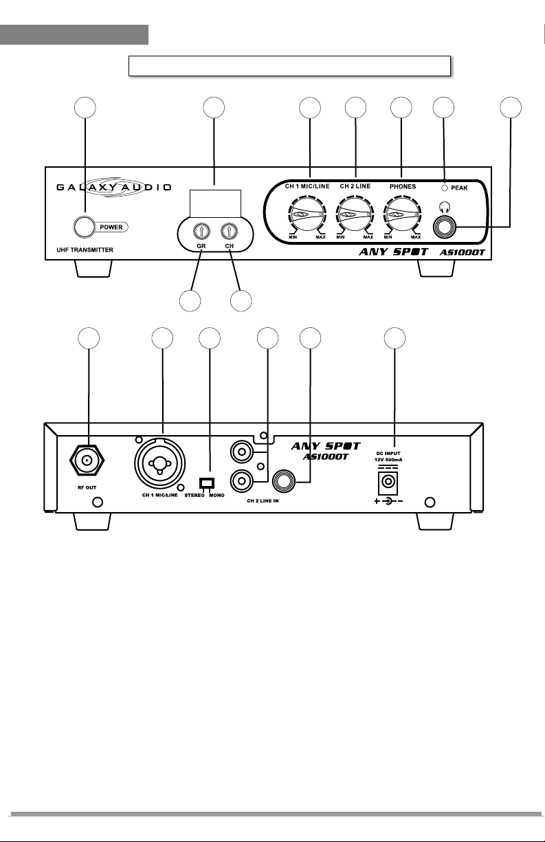
1. POWER: On/Off push button switch.
2. GR: Rotary switch used to select frequency group.
3. CH: Rotary switch used to select frequency channel.
4. LED display: Indicates the current frequency group and
channel selected on the transmitter.
5. CH 1 MIC/LINE: Adjusts the volume of the ¼" XLR MIC/LINE
input.
6. CH 2 LINE: Adjusts the volume of the stereo RCA and STEREO
1/4" LINE IN inputs.
7. PHONES: Adjusts the volume of the monitoring headphone
jack (#9).
8. PEAK: Illuminates when the input audio signal is too high.
Distortion may occur when this light is on.
3
Page 7

AS-1000R
9. HEADPHONE JACK: 1/4" stereo jack for headphones. This
jack is used to monitor the audio signal from the transmitter
location.
10. RF OUT: TNC socket for installation of antenna.
11. CH 1 MIC/LINE INPUT: Balanced 1/4" XLR combo jack for
microphone level (XLR), or line level (1/4") signals.
12. STEREO/MONO: Switch used to select stereo or mono
mode of CH 2 RCA and 1/4" LINE IN inputs.
13. CH 2 LINE IN: Stereo RCA jacks for mono or stereo audio
input.
14. CH 2 LINE IN: Stereo 1/4" jack for stereo or mono audio input.
Move switch (12) to Mono when a Mono 1/4" plug is used.
15. DC 12V: DC input connector for AC adapter.
AS-1000R Receiver
Features
Two 1/4-wave antennas for true diversity reception.
Two stereo 1/8" outputs for ear buds and interfacing with
recording equipment.
Multi-Color LED indicator allows the user to obtain more
status information from the receiver.
Charging input allows for re-charging of batteries without
having to remove them. (For use only with optional charger
unit and rechargeable batteries).
Up to 64 selectable frequencies are available to set up a
multi-frequency broadcasting system while avoiding
interference. The user can easily select the frequency
program number by using the rotary switches inside the
battery compartment.
The frequency group and channel selection switches are
contained inside the battery compartment, which helps
prevent the accidental changing of channels during use.
In the rare event of a signal dropout, our “Auto-Mute”
circuitry prevents intermittent static from going into the
users ears.
4
Page 8

AS-1000R
PRODUCT DESCRIPTION
4
3
2
1
10
5
11
GR CH
CH.
1
GR.
2
3
4
8
7
5
6
7
1
2
3
4
8
7
5
6
6
1. POWER: On/Off slide switch.
2. MULTI-COLOR LED INDICATOR:
A. When the power is first switched on, the LED flashes RED,
and then fades out.
B. A constant GREEN LED indicates a signal from the
transmitter is present plus fully charged batteries.
C. A constant AMBER LED indicates the batteries are low.
(Time to replace the batteries).
D. A constant RED LED indicates no signal from the transmitter
is present.
E. A flashing RED LED indicates the batteries are being
charged (only applies to rechargeable batteries and the
optional charger unit).
5
Page 9

AS-1000R
3. VOLUME CONTROL: Adjusts the volume of the signal
present at the ear bud jack (#6).
4. 1/4" WAVE ANTENNA
5. 1/8" STEREO RECORDING OUTPUT: Provides a stereo
line level signal to recording or other equipment. (Not
affected by the volume control #3).
6. 1/8" STEREO EAR BUD OUTPUT: Provides a stereo signal
to the ear buds.
7. BATTERY COMPARTMENT DOOR RELEASE.
9
8. BATTERY CHARGER INPUT: For use with the optional
battery charger (AS-DCC). (Use only with rechargeable type batteries.)
9. BELT CLIP: Allows the receiver to be easily worn on a belt,
waistband, or guitar strap.
10. GROUP and CHANNEL SELECTORS: Rotary switch (GR)
used to select group, and (CH) to select channel.
11. BATTERY COMPARTMENT: Holds two AA standard or
rechargeable batteries. (Observe correct polarity
indications.)
8
6
Page 10

AS-1000
SYSTEM SETUP & OPERATION
1. Make sure that both the AS-1000T Transmitter and
AS1000R Receiver power switches are in the off position
before beginning this procedure.
2. Install 2 fresh AA batteries into the AS1000R. Attach
headphones to the green headphone jack and turn the
headphone volume control to minimum. Move the power
switch to the ON position. The LED indicator should
illuminate Red for a few seconds and then go out. If the LED
lights up Green, first double check that the Transmitter power
switch is in the off position. If the LED remains Green even
when the Transmitter is switched off, adjust the group and
channel switches until the LED goes out. This will greatly
increase the likelihood that the Any Spot system will be
functioning on a frequency free from interference.
3. Attach the UHF antenna to the TNC connector on the rear
panel of the Transmitter. Check the voltage of the included
AC adapter, and make
sure it conforms to the line voltage available in your local
area. Using the wrong AC adapter may cause irreparable
damage to the unit. Plug the feeder cable of the AC adapter
into the DC IN jack on the Transmitter. Then plug the AC
adapter into a power outlet. Switch on the power button on
the Transmitter.
4. Adjust the Transmitter group and channel switches to
match the group and channel settings selected on the
AS1000R. Move the Transmitter power switch to the ON
position. The LED on the AS1000R should now illuminate
Green, indicating that it is receiving signal from the
Transmitter. If the LED on the AS1000R does not turn Green,
verify that the Transmitter and AS1000R have both been
adjusted to the same group and channel settings. If the AS1000R LED still does not turn Green, please try selecting a
new group and channel on both the Transmitter and
AS1000R to avoid any possible interference from outside RF
sources. Repeat this until the AS1000R LED turns Green.
5. Turn all volume controls on the Transmitter to minimum.
Connect the audio source(s) to the Transmitter. For Mic level
signals use the XLR (MIC) input jack. For Mono Line level
7
Page 11

AS-1000
signals use the ¼” (MIC) input jack. For Stereo Line level
signals use the Stereo RCA jacks. (The RCA jacks may also
be used in Mono by sliding the Stereo/Mono switch to Mono
mode).
6. Send audio signals from the source(s) at the approximate
level that will be used during the performance. Sources may be
a monitor mix from a mixing console, a CD player, or even a
single microphone.
7. Starting at minimum, slowly turn up the MIC volume control
(if Mic Input is used) until the Transmitter Peak LED starts to
light. Then turn the control back down just enough to keep the
LED from lighting. Repeat this procedure for the LINE IN volume
control (if used). These levels will be a good starting point and
provide a good signal to noise ratio while avoiding distortion. If
desired, the audio may be monitored at the Transmitter location
by plugging in headphones to the ¼” headphone jack. Adjust
PHONES Control to set the volume.
8. Now put on the Receiver headphones and slowly increase
the Receiver volume control until the desired level is achieved. If
both inputs on the Transmitter are in use, you may need to
adjust the balance between the MIC and LINE Volume Controls.
If the source audio levels provided to the Transmitter change,
the volume controls on the Transmitter may need to be readjusted for optimum performance.
9. Walk around the area where the Receiver(s) will be used to
ensure you have good coverage with no interference. If any
interference is heard, select a new frequency program number
on both the Transmitter and the Receiver until a clear frequency
is found. Once a frequency has been selected, additional
Receivers may be set to the same frequency and audio quality
verified.
10. A general rule for any wireless system: Any number of
Receivers may be set to the same frequency and used in the
same area. However, only one Transmitter may be used on a
selected frequency in any one area.
8
Page 12

Model no.
AS1000R
Frequency Range
UHF 682~698MHz. 64 CH
Case
Body-pack In Ear Monitor
Oscillator
PLL synthesized
Receiving Mode
Single channel. Diversity
Frequency Stability
±0.005%
Receiving Sensitivity
At 5 dBuV over 80dB S/N ratio
Image & Spurious
Rej.
80dB minimum
Selectivity
> 50dB
Modulation Mode
FM
IF Frequency
1st: 56MHz 2nd: 10.7MHz
Dynamic Range
>96dB
S/N Ratio
>94dB, at 15KHz deviation and 60dBuV antenna
input
AF Response
Headphone: 100Hz to 10KHz (±3dB)
Line: 100Hz to 10KHz (±3dB)
T.H.D.
<1%(at 1KHz)
Power Supply
DC 3V ( 2 x 1.5V AA batteries or rechargeable
batteries)
Audio Output
Headphone stereo output: 20mW, Line stereo
output level: -10dB
Current Consumption
130mA ± 10mA
Dimension W x H x D
3" x 4.2" x 1.2" (76 x 106 x 29mm)
AS-1000R
SPECIFICATION : AS-1000R Receiver
9
Design and specifications are subject to change without notice.
Page 13

Frequency range
UHF 682 ~ 698MHz
RF power output
100mW
Frequency stability
±0.005%
Maximum deviation
±48KHz with limiting compressor
Spurious emission
>60dB below carrier frequency
T.H.D.
<1% (at 1KHz)
Power supply
DC12 ~18V
Tone key
32.768 KHz
Current consumption
140mA ±10mA(100mW)
Dimension W x H x D
8.31" x 1.73" x 7.1" (211 x 44 x 180mm)
AS-1000T
SPECIFICATION
SPECIFICATION : AS-1000T Transmitter
Design and specifications are subject to change without notice.
10
Page 14

Problem Solution
No Sound
l Make sure both the transmitter and receiver are switched
on and receiving power.
l Make sure the transmitter and receiver are tuned to the
same frequency program number.
l Make sure an audio signal is being supplied to the
transmitter. Check by plugging a set of headphones into
the Phones jack on the transmitter.
l Make sure the receiver is within range of the transmitter.
l Check whether the transmitter is located too near a metal
object, or there are obstructions between the transmitter
and receiver.
Sound
interference
l Check the transmitter antenna location. Higher is better.
l When using 2 or more transmitters simultaneously, make
sure the chosen frequencies are not interfering with each
other.
l Check whether the interference comes from other
wireless systems, TV, radio, etc. Try choosing new
matching frequency program numbers for both the
transmitter and receiver.
Distortion
l Check the input volume control setting on the transmitter.
(See step #7 under Set-up and Operation).
l Make sure the receiver volume is not set too high.
l Make sure the source signal supplied to the transmitter is
not distorted.
AS-1000
11
TROUBLESHOOTING
Page 15

Frequency Chart
12
Page 16

AS-1000
Certification
AS-1000T: Certified to FCC Parts 74, FCC ID JEBIEM-168.Meets essential requirements of
European R&TTE Directive 1999/5/EC, eligible to bear CE marking. Type approved to EN
300 422 -2. Meets requirements of EMC Standard EN 301 489 Parts 1 and 9. Certified to EN
60065.
AS-1000R: Approved under the Declaration of Conformity (DoC) provision of FCC Part 15.
Meets essential requirements of European Union R&TTE Directive 1999/5/EC, eligible to
bear CE marking. Type approved to EN 300 422 -2. Meets requirements of EMC Standard
EN 301 489 Parts 1 and 9.
This Radio Equipment is intended for use IN MUSICAL PROFESSIONAL ENTERTAINMENT
AND SIMILAR APPLICATIONS.
SP41-120500 power supply conforms to applicable U.S. and Canadian electrical and safety
standards.
NOTE: This Radio apparatus may be capable of operating on some frequencies not
authorized in your region. Please contact your national authority to obtain information on
authorized frequencies for wireless microphone products in your region
Licensing: A ministerial license to operate this equipment may be required in certain areas.
Consult your national authority for possible requirements.
FCC Statement. The AS-1000R Receiver complies with Part 15 of the FCC rules. Operation
is subject to the following two conditions: (1) this device does not cause harmful interference,
and (2) this device must accept any interference received, including interference that may
cause undesired operation.
Licensing Statement. A user license may be required for operation. Contact the
communications authority in your country for more information.
Modifications to Approved Equipment. Changes or modifications not expressly approved
by Galaxy Audio Incorporated could affect compliance with telecommunications standards,
thereby voiding the user's authority to operate this product.
NOTE: This equipment has been tested and found to comply with
the limits for a Class B Digital Device, pursuant to Part 15 of the
FCC Rules. These limits are designed to provide reasonable
protection against harmful interference in a residential installation.
This equipment generates, uses and can radiate radio frequency
energy and, if not installed and used in accordance with the
instruction may cause harmful interference to radio communication.
However, there is no guarantee that interference will not occur in a
particular installation. If this equipment does cause harmful
interference to radio or television reception, which can be
determined by turning the equipment off and on, the user is
encouraged to try to correct the interference by one or more of the
following measures:
Reorient or relocate the receiving antenna.
Increase the separation between the equipment and receiver.
Connect the equipment into an outlet on a circuit different from
that to which the receiver is connected.
Consult the dealer or an experienced radio / TV technician for
help.
13
Page 17

NOTES
NOTES
14
Page 18

ONE YEAR LIMITED WARRANTY
This warranty gives you specific legal rights, and you may also have other rights which may
vary from state to state. This warranty is extended to the purchaser and to any purchaser from
him/her for value.
GALAXY AUDIO warrants the materials and workmanship of its products for a period of one
full year from the date of the original purchase.
The following are not covered by the warranty:
1. Damage to or deterioration of the exterior cabinet which occurs after delivery.
2. Damage after initial delivery resulting from accident, misuse or neglect.
3. Damage resulting from failure to follow instructions contained in the owner’s manual.
4. Damage resulting from the performance of repairs by someone other than GALAXY
AUDIO or an authorized GALAXY AUDIO service center.
5. Damage occurring during the shipment or delivery of any GALAXY AUDIO product to
GALAXY AUDIO or an authorized service center after initial delivery of the product to
you.
6. Damage to any GALAXY AUDIO product which has been altered, or on which the serial
number has been effaced or removed.
If your unit requires service, it must be returned, shipping charges prepaid to GALAXY
AUDIO service center in the United States. (This warranty is not enforceable outside the U.S.)
Please call or write GALAXY AUDIO, 601 E. Pawnee, Wichita, Kansas 67211,
(800) 369-7768. Under no circumstances should you return your unit to the factory without
first calling GALAXY AUDIO and acquiring a Return Authorization Number (RMA) or
written instruction to do so. If service is required, you must present the original or a copy of
the bill of sale as a proof of date of purchase of your unit. Upon receipt of your unit for
service, GALAXY AUDIO will repair or replace your unit as soon as possible, but in no event
later than 30 days after the receipt of the unit. We will return the unit to you, shipping charges
prepaid, provided the necessary repairs are covered by this warranty.
IMPLIED WARRANTIES OF MERCHANTABILITY AND FITNESS FOR PARTICULAR
PURPOSE ARE LIMITED IN DURATION TO THE LENGTH OF THIS WARRANTY,
UNLESS OTHERWISE PROVIDED FOR BY STATE LAW. GALAXY AUDIO’S
LIABILITY IS LIMITED TO THE REPAIR OR REPLACEMENT, AT OUR OPTION, OF
ANY DEFECTIVE PRODUCT, AND SHALL IN NO EVENT INCLUDE INCIDENTAL OR
CONSEQUENTIAL DAMAGES OF ANY KIND. SOME STATES DO NOT ALLOW
LIMITATIONS ON HOW LONG AN IMPLIED WARRANTY LASTS AND/OR DO NOT
ALLOW THE EXCLUSION OR LIMITATION OF INCIDENTAL OR CONSEQUENTIAL
DAMAGES, SO THE ABOVE LIMITATIONS AND EXCLUSIONS MAY NOT APPLY TO
YOU.
GALAXY AUDIO does not authorize any third party, including any dealer or Authorized
Service Center, to assume any liability on behalf of GALAXY AUDIO or to make any
warranty for GALAXY AUDIO.
1-800-369-7768 www.galaxyaudio.com
P.O. BOX 16285 Wichita, Ks 67216-0285
Specifications in this manual are subject to change without notice.
15
Page 19

REGISTRATION
REGISTRATION CARD
What magazines do you read?_________
_________________________________
_________________________________
__________________________________
_________________________________
_________________________________
How can Galaxy Audio better serve you?
_________________________________
_________________________________
_________________________________
_________________________________
__________________________________
_________________________________
Registration information is used ONLY by GALAXY
AUDIO and will be kept strictly confidential.
Name________________________Phone_____________
Registration
Address________________________________________
City, State, Zip____________________________________
email_______________________
Serial number Model
Dealer_______________________PurchaseDate________
This Galaxy Audio product will be used for:
Live Sound o
Church o
Recording
Home/Project Studio o
Commercial Studio o
Post-Production/Mastering o
Broadcast
On-Air o
Production o
Page 20

1-800-369-7768 www.galaxyaudio.com
P.O. BOX 16285 Wichita, Ks 67216-0285
WICHITA, KS 67216-0285
P.O. BOX 16285
GALAXY AUDIO
HERE
STAMP
PLACE
V2-06202007
 Loading...