

Page 1
Pub. 43003-023A
GAI-TRONICS® CORPORATION
A HUBBELL COMPANY
Model XCP0110A Replacement Button/
Elastomer Kit
Field Installation Kit Instructions
Confidentiality Notice
This manual is provided solely as an operational, installation, and maintenance guide and contains
sensitive business and technical information which is confidential and proprietary to GAI-Tronics.
GAI-Tronics retains all intellectual property and other rights in or to the information contained herein,
and such information may only be used in connection with the operation of your GAI-Tronics product or
system. This manual may not be disclosed in any form, in whole or in part, directly or indirectly, to any
third party.
General Information
The Model XCP0110A Replacement Button/Elastomer Kit allows the replacement of individual or
groups of heavily used buttons. It also includes replacements for all the button elastomers.
This kit includes the following components:
Qty Description Qty Description
3 Small elastomer switch 1 White 3 button
1 Large elastomer switch 1 White 4 button
10 White blank button 1 White 5 button
1 Red Transmit button 1 White 6 button
1 Long white button 1 White 7 button
4 Green Select button 1 White 8 button
8 Black button 1 White 9 button
4 Red Tx button 1 White 0 button
1 White 1 button 1 White # button
1 White 2 button 1 White * button
Page 1 of 4
Page 2
Pub. 43003-023A
Model XCP0110A Button/Elastomer Replacement Kit Page: 2 of 4
Installation
Button Installation
1. Disconnect the power from the ICP9000 Series Desktop Console.
2. The buttons can be easily removed without opening the console. Simply grasp a button on the top
and bottom with a pair of pliers and wiggle back and forth while pulling upwards.
3. To install the new button, push it gently into the slot until it clicks into position. Test the movement
of the button to assure proper installation.
Actuator Elastomer Installation
1. Disconnect the power from the ICP9000 Series Desktop Console.
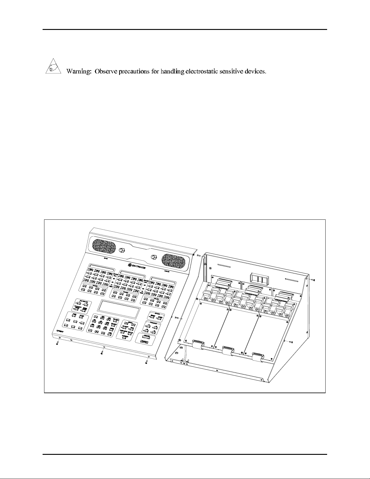
2. Remove the seven screws securing the top panel and gently lift the cover to expose the attached
speaker cable and master display cables. See Figure 1.
Figure 1.
3. Disconnect the speaker cable at the male to female connection point. Unplug the master display cable
from the top cover. Also unplug the ESD ground wire from the front panel quick-disconnect lug.
11/01
Page 3

Pub. 43003-023A
Model XCP0110A Button/Elastomer Replacement Kit Page: 3 of 4
4. Place the front cover face down on a flat surface. Remove the ten #4-40 hex nuts and four #4-40
screws securing the PCBA. See Figure 2.
Note: Be especially careful not to dislodge the buttons from the front panel.
Figure 2. Inside of Front Cover
5. Gently remove the PCBA from the front cover.
6. Once free, you will see four separate elastomer actuators attached to the front side of the PCBA.
Remove either the damaged or all four elastomers based upon repair requirements. See Figure 3.
11/01
Figure 3. PCBA with Elastomer
Page 4

Pub. 43003-023A
Model XCP0110A Button/Elastomer Replacement Kit Page: 4 of 4
7. To attach the new elastomers, position them in place, and with a small blunt-tipped object, gently
press the locating nubs into their respective locating holes.
8. When complete, reattach the PCBA in the reverse procedure. Then reassemble the front cover in the
reverse order. Check all buttons for proper actuation after assembly, and adjust as necessary.
9. Reconnect the power to the ICP9000 Series Desktop Console.
11/01
 Loading...