

Page 1

Pub. 43003-021E
GAI-TRONICS® CORPORATION
A HUBBELL COMPANY
Model XCP0100A 4-Channel Expansion Kit
Field Installation Kit Instructions
Confidentiality Notice
This manual is provided solely as an operational, installation, and maintenance guide and contains
sensitive business and technical information that is confidential and proprietary to GAI-Tronics.
GAI-Tronics retains all intellectual property and other rights in or to the information contained herein,
and such information may only be used in connection with the operation of your GAI-Tronics product or
system. This manual may not be disclosed in any form, in whole or in part, directly or indirectly, to any
third party.
General Information
The Model XCP0100A 4-Channel Expansion Kit expands the total number of channels in the ICP9000
CommandPLUS Series Console or the ICPN9000 Navigator Series MCU by four additional channels.
This kit includes the following components:
Qty Description
1 CP-CSD Slave PCBA
1 CP-CLP Slave Unit Suppression Circuit PCBA
1 CPSLAV2J EPROM (needed for backward compatibility only)
1 CP-LP-GND-JPR Surge Protection Ground Cable
10
1 SLV-CBL-M Interconnecting Cable (for Master PCBA-to-CSD PCBA)
1 SLV-CBL-P Interconnecting Cable (for CSD-to-CLP PCBAs)
1 CP-CBL-I/O Console I/O Cable (10-foot)
1 Envelope containing “Motorola Brand Hardware”:
#4-40 ¼-inch Phillips screws
#4-40 standoffs (qty. 3)
#4-40 5/16-inch screws (qty. 3)
#10-32 1 ½-inch screw
#10 washers (qty. 2)
#10-32 nut
#10-32 standoff
#4-40 3/16-inch screws (qty. 3)
M3 6mm screws (qty. 6)
#4 washers (qty. 6)
GAI-Tronics Corporation 400 E. Wyomissing Ave. Mohnton, PA 19540 USA
610-777-1374 800-492-1212 Fax: 610-796-5954
V
ISIT WWW.GAI-TRONICS.COM FOR PRODUCT LITERATURE AND MANUALS
Page 2
Pub. 43003-021E
Model XCP0100A 4-Channel Expansion Kit Page 2 of 7
Pre-Installation Notice
Before installing the CP-CSD Slave PCBA, the master firmware version of the ICP9000 Desktop or
Navigator Series Console must be determined. To determine the master firmware version, momentarily
depress the RESET button located on the rear panel of the unit. The master firmware version will appear
in the console display window (for approximately 5 seconds) as MAST, followed by a version number
and letter (example: MAST4D). If the version number/letter is “4x” or higher (“x” being an alphabetic
letter), no changes are required to the CP-CSD board and installation can continue.
If the version number/letter is “3x” or lower, the slave firmware must be changed due to incompatibility
with the master firmware and CARD Suite software (found on the XAC4000A Programming Bundle
CD). Observing precautions for handling electrostatically sensitive devices, remove EPROM No. 50086085 from socket U502. Install EPROM CPSLAV2J in its place. Installation can now continue.
N
OTE: If you are interested in upgrading your console to the latest feature firmware, upgrade kits are
available. Please contact our Customer Service department at 1-800-492-1212 for price and availability.
Installation
If installing this kit in the Motorola CommandPLUS, use the supplied hardware in the envelope
labeled “Motorola Brand Hardware.” See the “Motorola CommandPLUS Hardware Installation”
instructions on page 5 for this hardware only. For the remainder of the installation, follow the
instructions provided for the ICP 9000 Series Desktop Console. Motorola is a registered trademark
of Motorola Incorporated.
ICP9000 Series Desktop Console
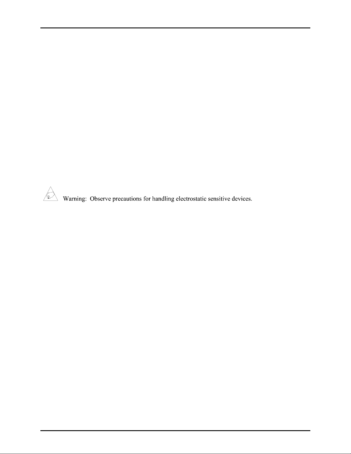
1. Disconnect the power from the ICP9000 Series Desktop Console and remove all attached cables from
the rear cover.
2. Remove the four screws securing the rear panel. Gently pull the rear cover from the housing and
disconnect the ribbon cables (SLV-CBL-P) attached to the surge suppression PCBA. Lay the rear
panel flat. See Figure 1.
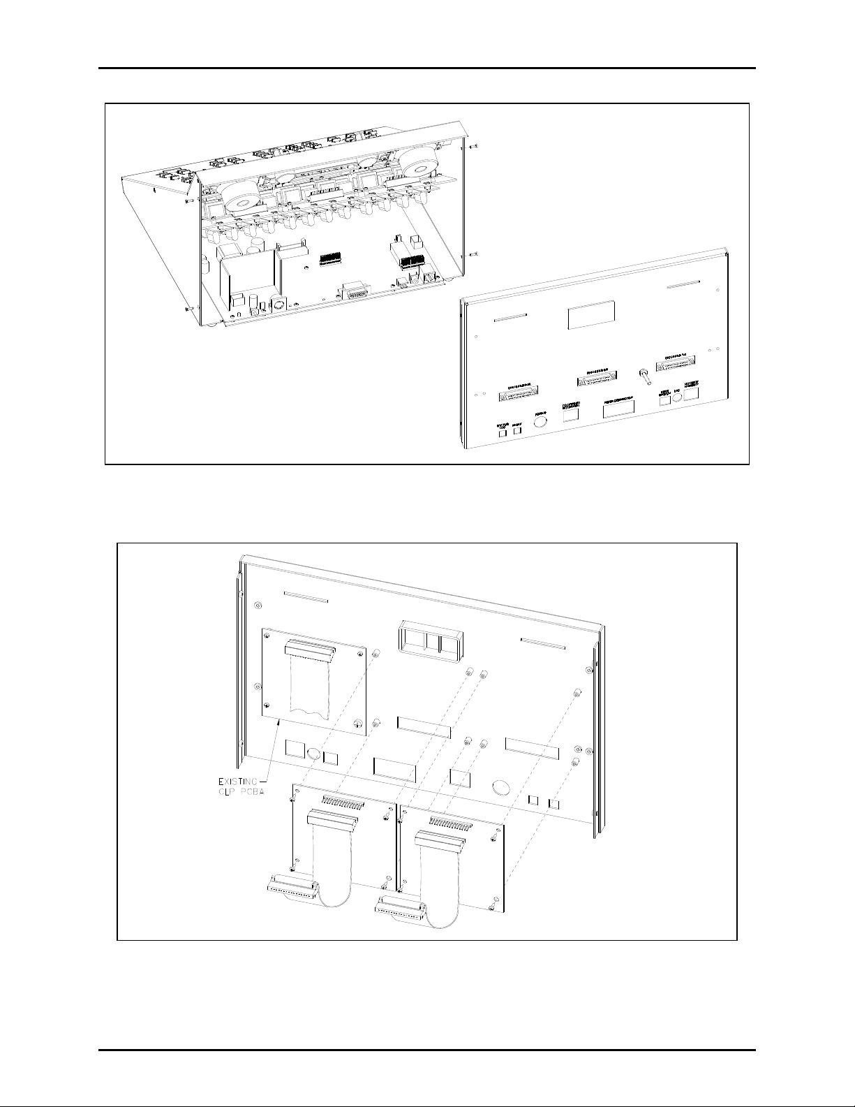
3. Mount the new CLP PCBA next to the existing CLP board using the four threaded stand-offs with the
#4-40 screws provided. See Figure 2.
4. Remove the earth ground terminal screw from the bottom right corner of the existing CLP PCBA.
Attach the supplied surge protection cable to the earth ground screw, and the other end to the
matching location on the new CLP PCBA.
5. Attach the SLV-CBL-P ribbon cable to its matching connectors between the CLP PCBA at J25 and
the CSD PCBA at P25. Also reattach the original ribbon cable.
f:\radio products-current release\43003\43003-021e\43003-021e.doc
03/12
Page 3
Pub. 43003-021E
Model XCP0100A 4-Channel Expansion Kit Page 3 of 7
Figure 1.
Figure 2. Inside of rear cover
N
OTE: Only one module is provided with each kit.
f:\radio products-current release\43003\43003-021e\43003-021e.doc
03/12
Page 4

Pub. 43003-021E
Model XCP0100A 4-Channel Expansion Kit Page 4 of 7
6. Replace the rear cover and screws ensuring that no cables are pinched between the housing and the
rear cover.
7. Remove the seven screws securing the top panel and gently lift the cover to expose the attached
speaker cable and master display cable. See Figure 3.
Figure 3.
8. Disconnect the speaker cable at the male-to-female connection point. Unplug the master display
cable from the top cover.
9. Mount the new CSD PCBA next to the existing CSD board(s) using the supplied #4-40 screws. Refer
to Figure 3.
10. Connect the supplied CSD-to-CPM ribbon cable to J1 and route it under the cable slot nearest the
mounting position. Plug the other end of the cable into either P2 on the CPM board, if expanding a 4channel console, or P3 on the CPM board if expanding an 8-channel console.
11. Reassemble the front cover using the reverse procedure. Verify the correct ribbon cable positioning
before tightening the slave mid-panel mounting screws to avoid damage to the cable.
12. Refer to the CARD Suite Software (found on the XAC4000A Programming Bundle CD) for
programming instructions specific to the new channels.
f:\radio products-current release\43003\43003-021e\43003-021e.doc
03/12
Page 5

Pub. 43003-021E
Model XCP0100A 4-Channel Expansion Kit Page 5 of 7
Motorola CommandPLUS Hardware Installation
Use the hardware supplied in the envelope labeled “Motorola Brand Hardware.”
1. Using the #4-40 5/16-inch screws, mount the three #4-40 standoffs to the rear of the panel in the
three holes located at the top and bottom of the panel next to the existing CLP board.
2. Insert the #10-32 1 ½-inch screw through the #10 washer, the surge protection cable’s ring lug, the
bottom-right hole of the CLP board, the #10-32 standoff, and through the panel. Secure the assembly
from the other side of the panel using the remaining #10 washer and the #10-32 nut.
3. Secure the CLP board to the rear-panel standoffs using the three #4-40 3/16-inch screws in the
remaining three holes.
4. Remove the earth ground terminal screw from the bottom right corner of the existing CLP board and
attach the other end of the surge protection cable to the earth ground screw.
5. Mount the new CSD board next to the existing CSD board(s) using the M3 6 mm screws and #4
washers.
ICPN9000 Navigator MCU
1. Disconnect the power from the ICPN9000 Navigator Series MCU and remove all attached cables
from the rear cover.
2. Remove the eight screws securing the rear panel. Gently pull the rear cover from the housing and
disconnect the ribbon cables (SLV-CBL-P) attached to the surge suppression PCBA. Lay the rear
panel flat. See Figure 4.
f:\radio products-current release\43003\43003-021e\43003-021e.doc
03/12
Figure 4.
Page 6

Pub. 43003-021E
Model XCP0100A 4-Channel Expansion Kit Page 6 of 7
3. Mount the new CLP PCBA next to the existing CLP board using the four threaded stand-offs with the
#4-40 screws provided. See Figure 5.
Figure 5. Inside of Rear Cover
N
OTE: Only one module is provided with each kit.
4. Remove the earth ground terminal screw from the bottom right corner of the existing CLP PCBA.
Attach the supplied surge protection cable to the earth ground screw, and the other end to the
matching location on the new CLP PCBA.
5. Attach the SLV-CBL-P ribbon cable to its matching connectors between the CLP PCBA at J25 and
the CSD PCBA at P25. Also reattach the original ribbon cable.
6. Replace the rear cover and screws ensuring that no cables are pinched between the main enclosure
and the rear cover.
f:\radio products-current release\43003\43003-021e\43003-021e.doc
03/12
Page 7

Pub. 43003-021E
Model XCP0100A 4-Channel Expansion Kit Page 7 of 7
7. Remove the 10 screws securing the side cover panel and gently lift the cover off. See Figure 6.
Figure 6.
8. Mount the new CSD PCBA next to the existing CSD board(s) using the supplied #4-40 screws. Refer
to Figure 6.
9. Connect the supplied CSD-to-CPM ribbon cable to J1 and route it under the cable slot nearest the
mounting position. Plug the other end of the cable into either P2 on the CPM board, if expanding a 4channel console, or P3 on the CPM board if expanding an 8-channel console.
10. Reassemble the side cover panel using the reverse procedure. Verify the correct ribbon cable
positioning before tightening the slave mid-panel mounting screws to avoid damage to the cable.
11. Refer to the CARD Suite Software (found on the XAC4000A Programming Bundle CD) for
programming instructions specific to the new channels.
f:\radio products-current release\43003\43003-021e\43003-021e.doc
03/12
Page 8

Warranty
Equipment. GAI-Tronics warrants for a period of one (1) year from the date of shipment, that any
GAI-Tronics equipment supplied hereunder shall be free of defects in material and workmanship, shall
comply with the then-current product specifications and product literature, and if applicable, shall be fit
for the purpose specified in the agreed-upon quotation or proposal document. If (a) Seller’s goods prove
to be defective in workmanship and/or material under normal and proper usage, or unfit for the purpose
specified and agreed upon, and (b) Buyer’s claim is made within the warranty period set forth above,
Buyer may return such goods to GAI-Tronics’ nearest depot repair facility, freight prepaid, at which time
they will be repaired or replaced, at Seller’s option, without charge to Buyer. Repair or replacement shall
be Buyer’s sole and exclusive remedy. The warranty period on any repaired or replacement equipment
shall be the greater of the ninety (90) day repair warranty or one (1) year from the date the original
equipment was shipped. In no event shall GAI-Tronics warranty obligations with respect to equipment
exceed 100% of the total cost of the equipment supplied hereunder. Buyer may also be entitled to the
manufacturer’s warranty on any third-party goods supplied by GAI-Tronics hereunder. The applicability
of any such third-party warranty will be determined by GAI-Tronics.
Services. Any services GAI-Tronics provides hereunder, whether directly or through subcontractors,
shall be performed in accordance with the standard of care with which such services are normally
provided in the industry. If the services fail to meet the applicable industry standard, GAI-Tronics will
re-perform such services at no cost to buyer to correct said deficiency to Company's satisfaction provided
any and all issues are identified prior to the demobilization of the Contractor’s personnel from the work
site. Re-performance of services shall be Buyer’s sole and exclusive remedy, and in no event shall GAITronics warranty obligations with respect to services exceed 100% of the total cost of the services
provided hereunder.
Warranty Periods. Every claim by Buyer alleging a defect in the goods and/or services provided
hereunder shall be deemed waived unless such claim is made in writing within the applicable warranty
periods as set forth above. Provided, however, that if the defect complained of is latent and not
discoverable within the above warranty periods, every claim arising on account of such latent defect shall
be deemed waived unless it is made in writing within a reasonable time after such latent defect is or
should have been discovered by Buyer.
Limitations / Exclusions. The warranties herein shall not apply to, and GAI-Tronics shall not be
responsible for, any damage to the goods or failure of the services supplied hereunder, to the extent
caused by Buyer’s neglect, failure to follow operational and maintenance procedures provided with the
equipment, or the use of technicians not specifically authorized by GAI-Tronics to maintain or service the
equipment. THE WARRANTIES AND REMEDIES CONTAINED HEREIN ARE IN LIEU OF AND
EXCLUDE ALL OTHER WARRANTIES AND REMEDIES, WHETHER EXPRESS OR IMPLIED BY
OPERATION OF LAW OR OTHERWISE, INCLUDING ANY WARRANTIES OF
MERCHANTABILITY OR FITNESS FOR A PARTICULAR PURPOSE.
Return Policy
If the equipment requires service, contact your Regional Service Center for a return authorization number
(RA#). Equipment should be shipped prepaid to GAI-Tronics with a return authorization number and a
purchase order number. If the equipment is under warranty, repairs or a replacement will be made in
accordance with the warranty policy set forth above. Please include a written explanation of all defects to
assist our technicians in their troubleshooting efforts.
Call 800-492-1212 (inside the USA) or 610-777-1374 (outside the USA) for help identifying the
Regional Service Center closest to you.
(Rev. 10/06)
 Loading...