

Page 1

Pub. 43003-017C
GAI-TRONICS® CORPORATION
A HUBBELL COMPANY
Model XCP0060A External
Full Duplex Phone Interface
Field Installation Kit Instructions
Confidentiality Notice
This manual is provided solely as an operational, installation, and maintenance guide and contains
sensitive business and technical information that is confidential and proprietary to GAI-Tronics.
GAI-Tronics retains all intellectual property and other rights in or to the information contained herein,
and such information may only be used in connection with the operation of your GAI-Tronics product or
system. This manual may not be disclosed in any form, in whole or in part, directly or indirectly, to any
third party.
General Information
The Model XCP0060A External Full Duplex Phone Interface Kit for the ICP9000 Series Desktop
Console or the ICP9000 Navigator Series MCU provides the capability of interfacing to an external
telephone. The kit includes the following components:
Qty Description
1 CTH External Full Duplex Phone Interface PCBA
1 Ground cable
1 Modular handset cord
3
3
2 #4-40 hex nuts
#4-40 × 0.25-inch Phillips screws
#4-40 × 0.75-inch M/F standoffs
Installation
ICP9000 Series Desktop Console
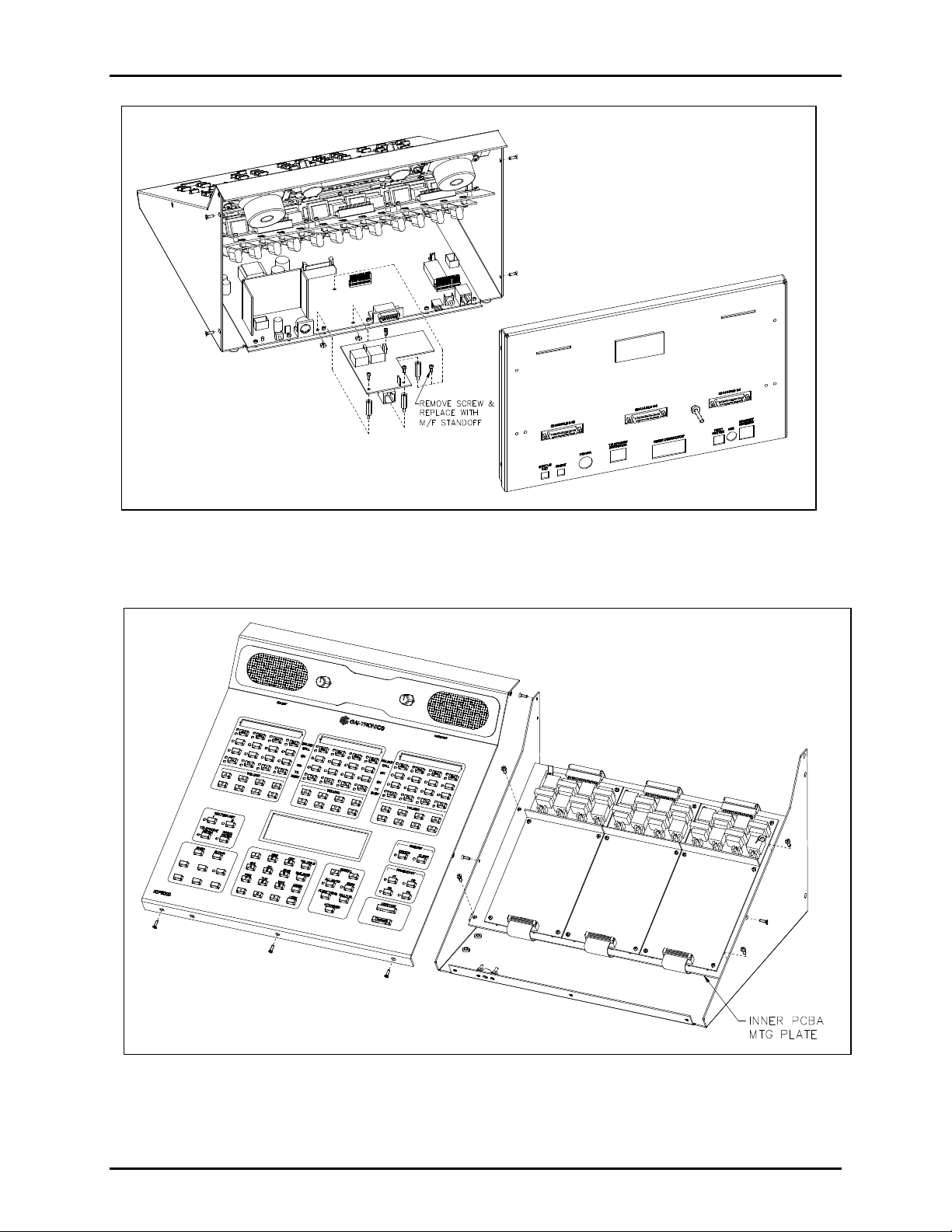
1. Disconnect power from the ICP9000 Series Desktop Console and remove all attached cables from the
rear cover.
2. Remove the 4 screws securing the rear panel. Gently pull the rear cover from the housing and
disconnect the ribbon cables (SLV-CBL-P) attached to the surge suppression PCBA. Lay the rear
panel flat. See Figure 1. (Do not install the phone PCBA at this point.)
GAI-Tronics Corporation P.O. Box 1060, Reading, PA 19607-1060 USA
610-777-1374 n 800-492-1212 n Fax: 610-775-6540
VISIT WWW.GAI-TRONICS.COM FOR PRODUCT LITERATURE AND MANUALS
Page 2
Pub. 43003-017C
Model XCP0060A External Full Duplex Phone Interface Kit Page: 2 of 5
Figure 1.
3. Remove the 7 screws securing the top panel and gently lift the cover exposing the attached speaker
cable and master display cable. See Figure 2.
Figure 2.
4. Disconnect the speaker cable at the male-to-female connection point. Unplug the master display
cable from the top cover.
11/02
Page 3

Pub. 43003-017C
Model XCP0060A External Full Duplex Phone Interface Kit Page: 3 of 5
5. Remove the 4 screws attaching the mounting plate to the base. This allows you to remove the
mounting plate giving you access to the main control PCBA. See Figure 2.
6. Remove the screw in the center of the main control PCBA. Screw in one of the supplied #4-40
male/female standoffs. See Figure 1.
7. Attach the remaining two standoffs in the two open holes highlighted by circles on the main control
PCBA. Place the threaded side through the holes and attach the supplied #4-40 nuts to the underside.
See Figure 1.
8. Place the CTH PCBA on the standoffs and attach with the supplied #4-40 screws. The J13 connector
plugs into the P13 connector on the main control PCBA. See Figure 1.
9. Attach the supplied ground cable to the ground screw located on the rear panel. Attach the other end
to the quick-disconnect on the CTH PCBA.
10. After the PCBA has been properly mounted, you may reassemble the console by reversing the
disassembly procedure. Verify that all CSD-to-main board ribbon cables are properly positioned into
their protective guides and connected to their respective main board connectors.
ICP9000 Navigator Series MCU
1. Disconnect power from the ICP9000 Navigator Series MCU and remove all attached cables from the
rear cover.
2. Remove the 8 screws securing the rear panel. Gently pull the rear cover from the housing and
disconnect the ribbon cables (SLV-CBL-P) attached to the surge suppression PCBA. Lay the rear
panel flat. See Figure 3. (Do not install the phone PCBA at this point.)
11/02
Figure 3.
Page 4

Pub. 43003-017C
Model XCP0060A External Full Duplex Phone Interface Kit Page: 4 of 5
3. Remove the 10 screws securing the side cover panel and gently lift the cover off. See Figure 4.
4. Remove the 4 screws attaching the mounting plate to the main enclosure. This allows you to remove
the mounting plate giving you access to the main control PCBA. See Figure 4.
Figure 4.
5. Remove the screw in the center of the main control PCBA. Screw in one of the supplied #4-40
male/female standoffs. See Figure 3.
6. Attach the remaining two standoffs in the two open holes highlighted by circles on the main control
PCBA. Place the threaded side through the holes and attach the supplied #4-40 nuts to the underside.
See Figure 3.
7. Place the CTH PCBA on the standoffs and attach with the supplied #4-40 screws. The J13 connector
plugs into the P13 connector on the main control PCBA. See Figure 3.
8. Attach the supplied ground cable to the ground screw located on the rear panel. Attach the other end
to the quick-disconnect on the CTH PCBA.
9. After the PCBA has been properly mounted, you may reassemble the MCU by reversing the
disassembly procedure. Verify that all CSD-to-main board ribbon cables are properly positioned into
their protective guides and connected to their respective main board connectors.
Other Connections
If this equipment is to be interfaced with an existing 911 PABX, the 8-pin modular connector supports the
incoming ringing closure input from the PABX, and the off-hook closure output to the PABX. Standard
8-pin modular plug tooling can be used to interface to the PABX. Refer to the table below for cable
pinout.
11/02
Page 5

Pub. 43003-017C
Model XCP0060A External Full Duplex Phone Interface Kit Page: 5 of 5
If this equipment is to be interfaced to a telephone set via the standard TX-RX 4-wire modular handset
cord, the provided handset cable can be used.
1. Plug the 8-pin end of the interface cable into the 8-pin modular jack on the CTH option board on the
ICP9000 Series Desktop Console rear panel or the ICP9000 Navigator Series MCU rear panel.
2. Disconnect the telephone set handset cord at the telephone set, and install the 4-pin end of the
interface cable in its place.
Your telephone dispatching is now through the console, using the OFF-HOOK/ANS key on the ICP9000
Series Desktop Console or the PHONE button on the toolbar of the ICP9000 Navigator GUI display in
addition to the function keys on your telephone set.
Pinout for CTH Modular Interface Connector
Pin No. Function
1, 8 Ringing closure input pair (Opto-Isolator)
2, 7 Off-Hook Closure Output Pair (100 ohm Opto-Relay)
3, 6 TX Audio OUT to PSTN Pair (Balanced)
4, 5 RX Audio IN from PSTN Pair (Balanced)
11/02
 Loading...