

Page 1

Pub. 43003-034B
GAI-TRONICS® CORPORATION
A HUBBELL COMPANY
Model XCP0600A
Navigator Output Control Mod ule Kit
Field Installation Kit Instructions
Confidentiality Notice
This manua l is provide d sole ly as an operatio nal, installation, and ma inte nance guide and conta ins
sensitive business and t e chnical informatio n tha t is confidentia l and pr opri et ary to GAI- Tronics.
GAI-Tronics retains all intellectual property and other rights in or to the information contained herein,
and such information may only be used in connection with the operation of your GAI-Tronics product or
system. This manu al may not be dis clos e d in any form, in whole or in pa rt, direct ly or i ndir ectly, to a ny
third pa r ty.
General Information
The Model XCP0600A Output Control Module Kit for the ICP9000 Series Navigator Console includes
the hardware and software necessary for plug and play installation, providing up to 32 output controls.
This kit is intended only for use in the ICP9000 Series Navigator Console and includes the following
components:
Qty Description
1 USB to DB9 converter, No. 69275-026
1 DB9 to Control Module Interface cable, No.61504-106
1 Naviga tor Soft ware CD
1 Output Control Module, No. 12584-xxx
2 Mounting screws, No. 28096-001
ATTENTION
Model 12584-xxx Output Control Module.
The Model 12584-xxx Output Control Module provides 32 digital outputs. The control module requires a
12 to 24 volt dc power supply. For communication and control by a Navigator MCU, the control module
is equipped with an RS-485 serial data interface.
This manual supercedes Pub. 42004-359 packaged with the
GAI-Tronics Corporation 400 E. Wyomissing Av e. Mohnton, PA 19540 USA
610-777-1374 800-492-1212 Fax: 610-796-5954
ISIT WWW.GAI-TRONICS.COM FOR PRODUCT LITERATURE AND MANUALS
V
Page 2

Pub. 43003-034B
Model XCP0600A Navi gator Output Control Module Kit Page: 2 of
Installation
Mechanical
The XCP0600A Output Control Module Kit is provided with a 25-foot DB9-to-RS-485 cable for
connection between user-provided PC and the Model 12584-xxx Output Control Module. This cable can
be spliced to extend this connection to a maximum of 5000 feet using standard telephone wire.
Mount the 12584-xxx to any wooden or prepared metal surface (pilot holes are required) using the #8 ×
3/4-inch screws provided with the kit.
Electrical
Wiring
6
WARNING
WARNING
Do not apply power until all the connections have been wired.
Connect only to a U L-listed Class 2 power source.
Please review Figure 1, the typical interconnection diagram, prior to beginning the installation.
Figure 1. Typica l Inst allation Block Diagram
\\s_eng\gtc proddoc s \ radio produc ts-current release\43003\ 43003-034b\ 43003-034b. doc
09/08
Page 3

Pub. 43003-034B
Model XCP0600A Navi gator Output Control Module Kit Page: 3 of
Data Connec tions
The Output Control Module supports both RS-485 and RS-232 data connections. A jumper (J6) is
provided to select either RS-485 or RS-232 data communications. Make certain that jumper J6
(located next to the RS-232 connector) is positioned between pins 2 and 3. Refer to Figure 2. The
RS-485 data connections are made directly to TB2, terminals 1 and 2. It is not required to observe
polarity.
6
Figure 2. Model 12584-xxx Output Control Module
Digital Ou tput Connec tions
The TB10 and TB9 connectors each provide 16 digital (common ground) output connections designed to
drive externally-mounted relays or other indicating circuits. Each output can sink up to 150 mA of the
current. External circuitry (relays, indicators, etc.) must be powered from an external power supply of the
same voltage used to power the Output Control Module (12 to 24 V dc), or from the same actual source.
The ground (or dc common) terminals of the external power supply must be tied to TB4-2 if two
individual power sources are used. Refer to Figure 2.
Table 1.
Terminal Labeled Function Type
TB10-1 to
TB10-16
TB9-1 to
TB9-16
OUT-1 TO
16
OUT-17 TO
32
Digital
output
Digital
output
Idle = +V dc, active (low) = sink100 mA maximum
Idle = +V dc, active (low) = sink100 mA maximum
Each output corresponds with the same number control push button on the Navigator Control Screen.
\\s_eng\gtc proddoc s \ radio produc ts-current release\43003\ 43003-034b\ 43003-034b. doc
09/08
Page 4
Pub. 43003-034B
Model XCP0600A Navi gator Output Control Module Kit Page: 4 of
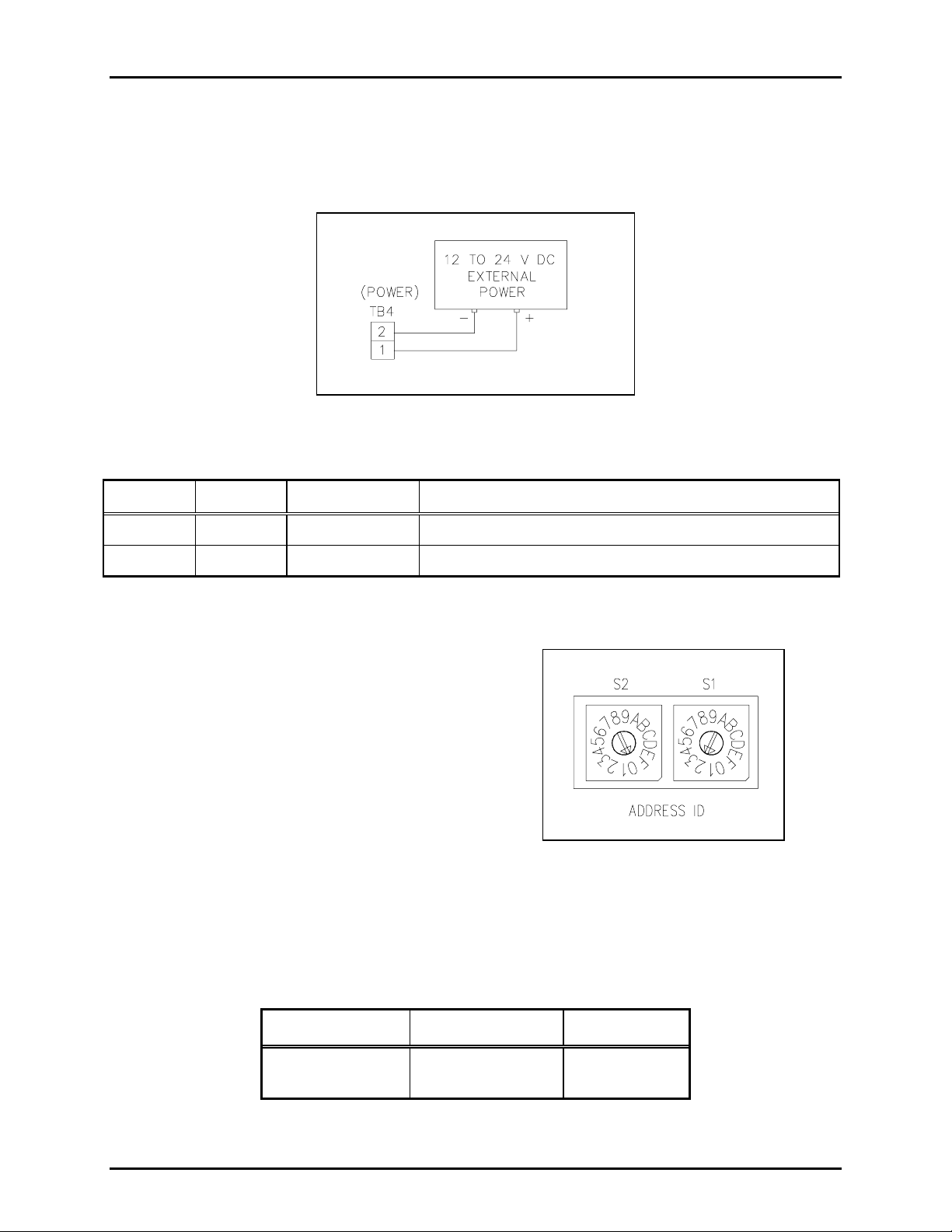
Power Con nections
The Output Control Module requires a dc power supply. The dc power supply voltage must be between
12 and 24 V dc. TB4 is used for power connections. Please refer to the TB4 terminal block assignment
chart and Figure 3 below.
Figure 3. Power connections at TB4
Table 2.
Terminal Labeled Description Function
6
TB4-1 + Power (+) 12 to 24 V dc power supply positive terminal
TB4-2 - Power (-) 12 to 24 V dc power supply negative terminal
Address S witches S1 a nd S2
S1 and S2 are hexadecimal switches that are used
to set the I/O Controller’s address. If the system
contains more than one I/O Controller, each device
must be set with a different address. The device’s
address should be set in sequential order starting
with address 01. Switch S2 sets the first digit and
switch S1 sets the second digit. See Figure 4.
Example:
Address 01: S2 = 0, S1 = 1
Address 02: S2 = 0, S1 = 2
Figure 4. Hex Switches S2 and S1
Address 03: S2 = 0, S1 = 3
OTE: After changing the board address, the RESET button must be momentarily depressed for the new
N
address to take effect.
Table 3.
Hex Switch Se ttings
Hex Switch No. Function Settings
S1 a nd S2 Board addr es s
\\s_eng\gtc proddoc s \ radio produc ts-current release\43003\ 43003-034b\ 43003-034b. doc
09/08
S1 = 2
S2 = 0
Page 5

Pub. 43003-034B
Model XCP0600A Navi gator Output Control Module Kit Page: 5 of
DIP Switch S4
An 8-p osition DI P switch S 4 sets the various data para me ters
and operation parameters of t he I/O Controll er.
Refer to Figure 5.
The following tables indicate each switch position and the
corresponding settings/functions. DIP switch S4 positions
1-2 set the serial data line baud rate as follows:
Table 4.
DIP Switc h S4 Position s 1–2: Baud Rate
Switch S4-1 Switch S4-2 Baud Rate
Closed Closed 2400
Figure 5. DIP Switch S4
Open Closed 4800
Closed Open 9600
6
Open Open 19200
Table 5.
DIP Switc h S4 Positi ons 3–8: Oper ating Parame ters
DIP Switch
Position
Function
Settings
S4-3 None – Not used N/A
S4-4 None – Not used N/A
S4-5 None – Not used N/A
S4-6
Automatic input
response
Closed – will wait for a poll request from master controlling
device before sending an input activation data message.
Open – will automatically send a data message when an
active input is detected. The controller will NOT wait for
poll request from the master controlling devise.
S4-7 Address return
Closed – will NOT return the controller’s address (set by hex
switch S1 and S2) when sending a data message to the master
controlling device.
Open – will return the controller’s address (set by hex switch
S1 and S2) when sending a data message to the master
controlling device.
S4-8
Data default
indication
Closed – if data communication is lost with the master
controlling device, all outputs will remain in their current
state until dat a commu n ic ati on is res tor e d.
Open – if data communication is lost with the master
controlling device, all outputs will flash on/off.
\\s_eng\gtc proddoc s \ radio produc ts-current release\43003\ 43003-034b\ 43003-034b. doc
09/08
Page 6

Pub. 43003-034B
Model XCP0600A Navi gator Output Control Module Kit Page: 6 of
Table 6.
DIP Switch S4 Default Settings
DIP Switc h S4 Function Settings
6
S4-1 Open
S4-2
Baud rate = 19.2 k
Open
S4-3 N/A Open
S4-4 N/A Open
S4-5 N/A Open
S4-6
Wait for poll request
Open
from master
S4-7
Return address to
Open
master controller
S4-8
Do not signal data
Closed
fault with master
Reset S witc h
A smal l push-button s wit ch is prov id e d to res tart the I/ O controll er’s mic ropr ocess or. M ome ntarily press
the button to initiate the reset sequence.
Specification s
Power Supply Require ments
Connection to a 12 to24 V dc (UL listed) Class 2 power source.....................................600 mA minimum
Power consumed............................................................................................................ 7 watts maxi mum
Auxiliary outputs....................................................Sink 150 mA maximum, per output to circuit common
and pulled up to the power input voltage
Mechanical
Enclosure.................................................................Steel body and cover; black fine-textured paint finish
Mounting .............................................................................................................................. Wall or shelf
Dimensions ..........................................................7.50 W× 5.625 D × 1.02 H inches (191 × 143 × 26 mm)
Weight .............................................................................................................................2 lbs. (0.902 kg)
Environmental
Temperature range................................................................................+32º F to +122º F (0º C to +50º C)
\\s_eng\gtc proddoc s \ radio produc ts-current release\43003\ 43003-034b\ 43003-034b. doc
09/08
 Loading...